

Page 1

Part No. 312410-A Rev 00
November 2000
600 Technology Park Drive
Billerica, MA 01821-4130
Installing and Operating AN/DC and ANH-8/DC Systems
Page 2

Copyright © 2000 Nortel Networks
All rights reserved. November 2000.
The information in this document is subject to change without notice. The statements, configurations, technical data,
and recommendations in this document are believed to be accurate and reliable, but are presented without express or
implied warranty. Users must t ak e full re spo nsibility fo r th eir a pplic a tio ns of any products specif i ed in th is d ocume nt .
The information in this document is proprietary to Nortel Networks NA Inc.
Trademarks
NORTEL NETWORKS is a trademark of Nortel Networks.
ACE, AFN, AN, BCN, BL N, BN, CN, F N, FR E, GAM E, L N, Optivity, and PPX are registered trademarks and ANH,
ASN, Bay•SIS, BCNX, BLNX, EZ Install, EZ Internetwork, EZ LAN, PathMan, PhonePlus, Quick2Config,
RouterMan, and SPEX are trademarks of Nortel Networks.
Microsoft, MS, MS-DOS, Windows, and Windows NT are registered trademarks of Microsoft Corporation.
All other trademarks and registered trademarks are t he property of their respective owners.
Statement of Conditions
In the interest of improvi ng internal design, operational fun c tion , an d/o r re liability , No rte l Networks NA Inc . rese rv e s
the right to make changes to the products described in this document without notice.
Nortel Networks NA Inc. does not assume any liability that may occur due to the use or application of the product(s)
or circuit layout(s) described her ein.
USA Requirements Only
Federal Communications Commission (FCC) Compliance Notice: Radio Frequency Notice
Note: This equipment has been tested and found to comply with the limits for a Class A digital device, pursuant to
Part 15 of the FCC rule s. These limits are designed to provide reasonable prote ct io n against harmful interference
when the equipment is operated in a commercial environment. This equipment ge nerates, uses, and can radiate radio
frequency energy. If it is not installed and used in accordance with the instruction manual, it may cause harmful
interference to radio communications. Operation of this equipment in a residential area is likely to cause harmful
interference, in which case users will be required to take whatever measures may be necessary to correct the
interference at their own expense.
European Requirements Only
EN 55 022 Statement
This is to certify that the Nortel Networks BN router is shielded against the generation of radio interference in
accordance with the application of Council Directive 89/336/EEC, Article 4a. Conformity is declared by the
application of EN 55 022 Class A (CISPR 22).
Warning: This is a Class A product. In a domestic env iron m ent, this product may cause radio interferen ce, in which
case, the user may be required to take appropriate measures.
Achtung: Dieses ist ein Gerät der Funkst örgrenzwertklasse A. In Wohnbereichen können bei Betrieb dieses Gerätes
Rundfunkstörungen auftreten, in welchen Fällen der Benutzer für entsprechende Gegenmaßnahmen verantwortlich
ist.
Attention: Ceci est un produit de Classe A. Dans un environnement domestique, ce produit risque de créer des
interférences radioélectriques, il appartiendra alors à l’utilisateur de prendre les mesures spécifiques appropriées.
ii
312410-A Rev 00
Page 3

EC Declaration of Conformity
This product conforms (or these products conform) to the provisions of Council Directive 89/336/EEC and
73/23/EEC.
Japan/Nippon Requirements Only
Voluntary Control Council for Interference (VCCI) Statement
Taiwan Requirements
Bureau of Standards, Metrology and Inspection (BSMI) Statement
Canada Requirements Only
Canadian Department of Communications Radio Interference Regulations
This digital apparatus (BN router) does not exceed the Class A limits for radio-noise emissions from digital apparatus
as set out in the Radio Interference Regulations of the Canadian Department of Communications.
Règlement sur le brouillage radioélectrique du ministère des Communications
Cet appareil numérique (BN router) respecte les limites de bruits radioélectriques visant les appareils numériques de
classe A prescrites dans le Règlement sur le brouillage radioélectrique du ministère des Communications du Canada.
Canada CS-03 Rules and Regulations
Notice: The Industry Canada label identifies certified equipment. This certification means that the equipment meets
telecommunications netw ork prote cti ve, opera tional and safety re quirements as pres cribed in the app ropriate Term inal
Equipment Technical Requirements document(s). The Department does not guarantee the equipment will operate to
the user’s satisfaction.
Before installing this equipment, u sers shou ld e nsure that it is permissible to be connected to the facilities of the local
telecommunications company. The equipment must also be installed using an acceptable method of connection. The
customer should be aware that compliance with the above conditions may not prevent the degradation of service in
some situations.
312410-A Rev 00
iii
Page 4

Canada Requirements Only
Repairs to certified equipment should be coordinated by a representative designated by the su pplier. Any repairs or
alterations made by the user to this equipment, or equipment malfunctions, may give the telecommunications
company cause to request the user to disconnect the equipment .
Users should ensure for their own protection tha t the electrical gro und connecti ons of the po wer utility, tele phone lines
and internal metallic water pipe system, if present, are connected together. This precaution may be particularly
important in rural areas.
Caution: Users should not attempt to make such connections themselves, but should contact the appropriate electric
inspection authority, or electric ia n, as appro p ria te.
Notice: For equipment using loopstart lines, please note that the Ringer Equivalence Number (REN) assigned to each
terminal device provides an indication of the maximum number of terminals allowed to be connected to a telephone
interface. The termination on an interface may consist of any combination of devices subject only to the requirement
that the sum of the Ringer Equivalence Numbers of all the devices does not exceed 5. The REN is located on the “FCC
Rules Part 68” label located on the bracket of the module, or on the back of the unit.
Canada CS-03 -- Règles et règlements
Avis: L'étiquette d'Industrie Canada identifie le matériel homologué. Cette étiquette certifie que le matériel est
conforme aux normes de protection, d'exploitation et de sécurité des réseaux de télécommunications, comme le
prescrivent les documents concernant les exigences techniques relatives au matériel terminal. Le Ministère n'assure
toutefois pas que le matériel fonctionnera à la satisfaction de l'utilisateur.
Avant d'installer ce matériel, l'utilisateur doit s'assurer qu'il est permis de le raccorder aux installations de l'entreprise
locale de télécommunication. Le matériel doit également être installé en suivant une méthode acceptée de
raccordement. L'abonné ne doi t pas oublier qu'il est possible que la conformité aux conditio ns énoncées ci-dessus
n'empêche pas la dégradation du service dans certaines s it uations.
Les réparations de matériel homologué doivent être coordonnées par un représentant désigné par le fournisseur.
L'entreprise de télécomm unication s pe ut d emande r à l' utilisat eur de débra ncher u n app areil à la su ite de rép arations o u
de modifications effectuées par l'utilisateur ou à cause de mauvais fonctionnement.
Pour sa propre protectio n, l 'utilisateur doit s'assurer que tous les f ils d e mise à la te rre de la sou rce d 'éner gie électriqu e,
des lignes téléphoniques et des canalisations d'eau métalliques, s'il y en a, sont raccordés ensemble. Cette précaution
est particulièrement importante dans les régions rurales.
Avertissement: L'utilisateur ne d oi t p as ten ter d e f a ire c es racco rde m ents lu i-m ême; i l do it avoir recour s à un se rvice
d'inspection des installati ons électriques, ou à un électricien, selon le cas.
Avis: Veuillez prendre note que pour tout appareillage supportant des lignes de type “loopstart,” l'indice d'équivalence
de la sonnerie (IES) assigné à chaque dispositif terminal indique le nombre maximal de terminaux qui peuvent être
raccordés à une interface. La terminaison d'une interface téléphonique peut consister en une combinaison de quelques
dispositifs, à la seule condition q ue la somme d'indi ces d'équi v alence de la sonnerie de to us les dispositifs n' excède p as
5. Le REN figure sur l’étiquette “FCC Rules Part 68” située sur le support du module ou à l’arrière de l’unité.
(continued)
iv
312410-A Rev 00
Page 5

FCC Part 68 Compliance Statement
This equipment complies with Pa rt 68 of FCC Ru les. All dire ct c onnec tio ns to telep hone ne tw o r k line s mu st be mad e
using standard plugs and jacks compliant with FCC Part 68. Please note the following:
1. You are required to request service from the telephone company before you connect the unit to a network. When
you request service, you must pro vide the teleph on e compa ny with the following data:
• When you request T1 Service, you must provide the telephone company with
-- The Facility Interface Code
Provide the telephone company with all the codes below:
- 04DU9-BN (1.544 MB, D4 framing format)
- 04DU9-DN (1.544 MB, D4 framing format with B8ZF coding)
- 04DU9-1KN (1.544 MB, ESF framing format)
- 04DU9-1SN (1.544 MB, ESF framing format with B8ZF coding)
- 04DU9-1ZN (1.544 MB, ANSI ESF and ZBTSI without line power)
The telephone company will select the code it has available.
-- The Service Order Code(s) (SOC): 6.0F
-- The req uired Universal Service Order Code (USOC) jack: RJ48C
• When you request Primary Rate ISDN Service, you must provide the telephone company with
-- The Facility Interface Code: 04DU9-1SN (1.544 MB, ESF framing format with B8ZF coding)
-- The Service Order Code(s) (SOC): 6.0F
-- The req uired Universal Service Order Code (USOC) jack: RJ48C
2. Your telephone company may make changes to its facilities, equipment, operations, or procedures that could
affect the proper function in g of yo ur equip m ent. The teleph on e com pany will notify you in advan ce of suc h
changes to give you an opportunity to maintain uninterrupted telephone service.
3. If the unit causes harm to the telephone network, the telephone company may temporarily discontinue your
service. If possible, they will notify you in advance, but if advance notice is not practical, you will be notified
as soon as possible and will be informed of your right to file a complaint with the FCC.
4. If you experience trouble with the unit, pl ease contact the Nortel Networks Technical Solutions Center in
your area for service or rep a irs. Repairs should be pe rformed only by service pe rsonnel authorized by
Nortel Networks.
United States 1-800-2LANWAN
Valbonne, France 33-4-92-96-69-68
Sydney, Australia 61-2-9927-8800
Tokyo, Japan 81-3-5740-1700
5. You are required to notify the telephone company when you disconnect the unit from the network.
312410-A Rev 00
v
Page 6

Nortel Networks NA Inc. Software License Agreement
NOTICE: Please carefully read this license agre ement before copying or using the accompanying software or
installing the hardware unit with pre-enabled software (each of which is referred to as “Software” in this Agreement).
BY COPYING OR USING THE SOFTWARE, YOU ACCEPT ALL OF THE TERMS AND CONDITIONS OF
THIS LICENSE AGREEMENT. THE TERMS EXPRESSED IN THIS AGREEMENT ARE THE ONLY TERMS
UNDER WHICH NORTEL NETWORKS WILL PERMIT YOU TO USE THE SOFTWARE. If you do not accept
these terms and conditions, return the product, unused and in the original shipping container, within 30 days of
purchase to obtain a credit for the full purchase price.
1. License grant. Nortel Networks NA Inc. (“Nortel Networks”) grants the end user of the Software (“Licensee”) a
personal, nonex clusive, nontransferable license: a) to use the So ftw are eit her on a single c omputer or, if applicable, on
a single authorized device identified by host ID, for which it was originally acquired; b) to copy the S of tware solely
for backup purposes in support of authorized use of the Software; and c) to use and copy the associated user manu al
solely in support of autho rized us e of the So ftw are by Licensee. Th is license a pplies to th e Softwa re only a nd does not
extend to Nortel Networks Agent software or other Nortel Networks software products. Nortel Netwo rks Agent
software or other Nortel Networks software products are licensed for use under the terms of the applicable N ortel
Networks NA Inc. Software License Agreement that accompanies such software and upon payment by the end user of
the applicable license fees for such software.
2. Restrictions on use; reservation of rights. The Software and user manuals are protected under copyright laws.
Nortel Networks and/or its licensors retain all title and ownership in both the Software and user manuals, including
any revisions made by Nortel Networks or its licensors. The copyright notice must be reproduced and included with
any copy of any portion of the Software or user manuals. Licensee may not modify, translate, decompile, disassemble,
use for any competitive analysis, reverse engineer, distribute, or create derivative works from the Software or user
manuals or any copy , in whole or in part. Except as expressly provided in this Agreement, Licensee may not copy or
transfer the Software or user manuals, in whole or in part. The Software and user manuals embody Nortel Networks’
and its licensors’ confidential and proprietary intellectual property. Licensee shall not sublicense, assign, or otherwise
disclose to any third party the Software, or any information about the operation, design, performance, or
implementation of the Software and user manuals that is confidential to Nortel Networks and its licensors; however,
Licensee may grant permission to its consultants, subcontractors, a nd agents to use the Softw are at Licensee’s facility,
provided they have agreed to use the Software only in accordance with the terms of this license.
3. Limited warranty . Nortel Networks warrants each item of Software, as delivered by Nortel Networks and properly
installed and operated on Nortel Networks hardware or other equipment it is originally licensed for, to function
substantially as described in its accompanying user m anual during its warranty period , which begins on the date
Software is first shipped to Licensee. If an y item of S oftware f ails to so function d uring its w arranty period, as the sole
remedy Nortel Networks will at its discretion provide a suitable fix, patch, or workaround for the problem that may be
included in a future Software release. Nortel Networks further warrants to Licensee that the media on which the
Software is provided will be free from defec ts in materials and wo rkman ship under no rmal use for a peri od of 90 da ys
from the date Software is first shipped to Licensee. Nortel Networks will replace defective media at no charge if it is
returned to Nortel Netw orks during the warranty period along with proof of the date of sh ipment. This warrant y does
not apply if the media has been damaged as a result of accident, misuse, or abuse. The Licensee assumes all
responsibility for selection of the Software to achieve Licensee’s intended results and for the installation, use, and
results obtained from the Software. Nortel Networks does not warrant a) that the functions contained in the software
will meet the Licensee’s requirements, b) that the Software will operate in the hardware or software combinations that
the Licensee may select, c) th at the operation of the Software will be uninterrupted or error free, or d) that all defects
in the operation of the Softw are will be corrected . Nortel Network s is not obligated to remedy any Software de fect that
cannot be reproduced with the latest Software release. These warranties do not apply to the Software if it has been
(i) altered, except by Nortel Networks or in accordance with its instructions; (ii) used in conjunction with another
vendor’s product, resulting in the de fect; or (iii) damaged by improper environment, abuse, mi suse, accident, or
negligence. THE FOREGOING WARRANTIES AND LIMITATIONS ARE EXCLUSIVE REMEDIES AND ARE
IN LIEU OF ALL OTHER WARRANTIES EXPRESS OR IMPLIED, INCLUDING WITHOUT LIMITATION ANY
WARRANTY OF MERCHANTABILITY OR FITNESS FOR A PARTICULAR PURPOSE. Licensee is responsible
vi
312410-A Rev 00
Page 7

for the security of its own data and information and for maintaining adequate procedures apart from the Software to
reconstruct lost or altered files, data, or programs.
4. Limitation of liability. IN NO EVENT WILL NORTEL NETWORKS OR ITS LICENSORS BE LIABLE FOR
ANY COST OF SUBSTITUTE PROCUREMENT; SPECIAL, INDIRECT, INCIDENTAL, OR CONSEQUENTIAL
DAMAGES; OR ANY DAMAGES RESULTING FROM INACCURATE OR LOST DATA OR LOSS OF USE OR
PROFITS ARISING OUT OF OR IN CONNECTION WITH THE PERFORMANCE OF THE SOFTWARE, EVEN
IF NORTEL NETWORKS HAS BEEN ADVISED OF THE POSSIBILITY OF SUCH DAMAGES. IN NO EVENT
SHALL THE LIABILITY OF NORTEL NETWORKS RELATING TO THE SOFTWARE OR THIS AGREEMENT
EXCEED THE PRICE PAID TO NORTEL NETWORKS FOR THE SOFTWARE LICENSE.
5. Government licensees. This provision applies to all Software and documenta tion acqu ired direc tly or indi rectly by
or on behalf of the United States Government. The Software and documentation are commercial products, licensed on
the open market at market prices, and were developed entirely at private expense and without th e use of any U.S.
Government funds. The license to the U.S. Government is granted only with restricted rights, and use, duplication, or
disclosure by the U.S. Government is subject to the restrictions set forth in subparagraph (c)(1) of the Commercial
Computer Software––Restricte d Rig hts cla u se o f FAR 52.227-19 and the limita tio ns se t out in this license for civilian
agencies, and subparagraph (c)(1)(ii) of the Rights in Technical Data and Computer Software clause of DFARS
252.227-7013, for agencies of t he Department of Defense or their successors, whichever is applicable.
6. Use of software in the European Community. This provision applies to all Software acquired for use within the
European Community. If Licensee uses the Software within a country in the European Community, the Software
Directive enacted by the Council of European Commun ities Directive dated 14 May, 1991, will apply to the
examination of the Software to facilitate interoperability. Licensee agrees to notify Nortel Networks of any such
intended examination of the Software an d may procure support and assista nce from Nortel Networks.
7. Term and termination. This license is effective until terminate d; however, all of the restrictions with respect to
Nortel Networks’ copyright in the Software and user manuals will cease being effective at the date of expiration of the
Nortel Networks copyright; those restrictions relating to use and disclosure of Nortel Networks’ confidential
information shall continue in effect. Licensee may terminate this license at any time. The license will automatically
terminate if Licensee fails to comply with any of the terms and conditions of the license. Upon termination for any
reason, Licensee will immediat ely destroy or return to Nortel Networks the Software, user manuals, and all copies.
Nortel Networks is not liable to Licensee for damages in any form solely by reason of the termination of this license.
8. Export and re-export. Licensee agrees not to export, directly or in directly, the Software or related technical data or
information without f irst obtain ing a n y required e xport lice nses or oth er go v ernme ntal ap pro v als. W i thout limiting the
foregoing, Lice n see, on behalf of itself and its subsidiaries a n d affiliates, agrees that it will n ot , without first obtaining
all export licenses and approvals required by the U.S. Government: (i) export, re-export, transfer, or divert any such
Software or technical data, or any direct product thereof, to any country to which such exports or re-exports are
restricted or embargoed under United States export control laws and regulations, or to any national or resident of such
restricted or embargoed countries; or (ii) provide the Software or related technical data or information to any military
end user or for any military end use, including the design, development, or production of any chemical, nuclear, or
biological weapons.
9. General. If any provision of this Agreement is held to be invalid or unenf orceable by a court of competent
jurisdiction, the remainder of the provisions of this Agreement shall remain in full force and effect. This Agreement
will be governed by the laws of the state of California.
Should you have any questions concerning this Agreement, contact Nortel Netw orks, 4401 Great America Parkway,
P.O. Box 58185, Santa Clara, Ca lifornia 95054-8 185.
LICENSEE ACKNOWLEDGES THAT LICENSEE HAS READ THIS AGREEMENT, UNDERSTANDS IT, AND
AGREES TO BE BOUND BY ITS TERMS AND CONDITIONS. LICENSEE FURTHER AGREES THAT THIS
AGREEMENT IS THE ENTIRE AND EXCLUSIVE AGREEMENT BETWEEN NORTEL NETWORKS AND
LICENSEE, WHICH SUPERSEDES ALL PRIOR ORAL AND WRITTEN AGREEMENTS AND
COMMUNICATIONS BETWEEN THE PARTIES PERTAINING TO THE SUBJECT MATTER OF THIS
AGREEMENT. NO DIFFERENT OR ADDITIONAL TERMS WILL BE ENFORCEABLE AGAINST
NORTEL NETWORKS UNLESS NORTEL NETWORKS GIVES ITS EXPRESS WRITTEN CONSENT,
INCLUDING AN EXPRESS WAIVER OF THE TERMS OF THIS AGREEMENT.
312410-A Rev 00
vii
Page 8

Page 9

Contents
Preface
Before You Begin ............................................................................................................xvii
Text Conventions ...........................................................................................................xviii
Acronyms ........................... .......................... .......................... ......................... .................x ix
Hard-Copy Technical Manuals ........ ...... ....... ...................................... ....... ...... ....... ...... ....x xi
How to Get Help ..............................................................................................................xxi
Chapter 1
Installing the AN/DC
Preparing for Installation .................................................................................................1-1
Verifying Shipment Contents ....................................................................................1-1
Supplying Tools and Equipment ...............................................................................1-3
Tools ..................................................................................................................1-3
Cables ............................................. ...... ....... ...... ....................................... ...... ...1-3
Service Consol e .......................................... ...... ....... ...... ...................................1-4
Mounting Hardware .... ....... ...... ....... ...... ....... ...... ....................................... ...... ...1-4
Verifying Site Requirements .....................................................................................1-4
Space Requirements .........................................................................................1-5
Electrical Requirements .....................................................................................1-5
Environmental Requirements ............................................................................1-5
Installing the AN/DC .......... ...... ....................................... ....... ...... ...... ....... ...... ....... ...... ...1-6
Positioning the AN/DC on a Flat Surface .................................................................1-6
Installing the AN/DC in a Rack .................................................................................1-6
Mounting the AN/DC on a Wall ................................................................................1-9
Connecting Communications Cables ................. ....... ...... ....... ...... ...... ....... ....................1-11
312410-A Rev 00
ix
Page 10

Connecting a Management Console or Modem ...........................................................1-12
Connecting a Terminal Console .............................................................................1-12
Connecting a PC Console ......................................................................................1-14
Connecting a Modem .............................................................................................1-16
Connecting to the DC Power Source ............................................................................1-18
Chapter 2
Installing the ANH-8/DC
Preparing for Installation .................................................................................................2-1
Verifying Shipment Contents ....................................................................................2-2
Supplying Tools and Equipment ...............................................................................2-3
Tools ..................................................................................................................2-3
Cables ............................................. ...... ....... ...... ....................................... ...... ...2-4
Service Consol e .......................................... ...... ....... ...... ...................................2-4
Mounting Hardware .... ....... ...... ....... ...... ....... ...... ....................................... ...... ...2-4
Verifying Site Requirements .....................................................................................2-5
Space Requirements .........................................................................................2-5
Electrical Requirements .....................................................................................2-5
Environmental Requirements ............................................................................2-6
Installing the ANH-8/DC ........................................... ...... ....... ...................................... ...2-6
Positioning the ANH-8/DC on a Flat Surface ...........................................................2-6
Installing the ANH-8/DC in a Rack ...........................................................................2-7
Mounting the ANH-8/DC on a Wall .........................................................................2-10
Connecting Communications Cables ................. ....... ...... ....... ...... ...... ....... ....................2-12
Connecting an AUI Cable .......................................................................................2-12
Connecting Ethernet Repeater Port UTP Cables ...................................................2-13
Using the MDI/MDI-X Switch ...........................................................................2-13
Connecting the ANH-8/DC to Other Repeaters/Hubs .....................................2-14
Connecting a Second Ethernet Interface UTP Cable .............................................2-17
Connecting Synchronous Cables ...........................................................................2-18
Connecting an ISDN Cable ....................................................................................2-19
Connecting a Management Console or Modem ...........................................................2-20
Connecting a Terminal Console .............................................................................2-20
Connecting a PC Console ......................................................................................2-22
Connecting a Modem .............................................................................................2-23
Connecting to the DC Power Source ....................................................................2-26
x
312410-A Rev 00
Page 11

Chapter 3
Starting the AN/DC and ANH-8/DC
About Software Installation ...... ....... ...... ....... ...... ....... ...... ....... ...... ...................................3-1
Boot Options ............................................................................................................3-2
Installing the Flash Memor y Card ...................... ....... ...... ....... ...... ...... ....... ...... ................3-3
Using EZ Install ..............................................................................................................3-5
Using Netboot, Directed Netboot, or Local Boot .............................................................3-6
Logging In to the Diagnostic Monitor ........................................................................3-6
Continuing with Netboot ...........................................................................................3-9
Continuing with Directed Netboot ...........................................................................3-12
Continuing with Local Boot .....................................................................................3-15
Chapter 4
Operating the AN/DC and ANH-8/DC
Ensuring a Successful Installation ..................................................................................4-2
AN/DC LED Descriptions ................................................................................................4-4
Front-Panel LEDs .....................................................................................................4-4
Back-Panel LEDs .....................................................................................................4-5
ANH-8/DC LED Descriptions ..........................................................................................4-6
Front-Panel LEDs .....................................................................................................4-6
Back-Panel LEDs .....................................................................................................4-7
Powering On and Off ......... ...... ....... ...... ....... ...... ....... ...... ....... ...... ...... .............................4-8
Resetting the AN/DC or ANH-8/DC ..............................................................................4-10
AN/DC Reset Switch ..............................................................................................4-11
ANH-8/DC Reset Switch ........................................................................................4-11
Removing a Flash Memory Card ..................................................................................4-12
Protecting Memory Card Files ......................................................................................4-13
Appendix A
Configuring Netboot and Directed Netboot
Using the ifconfig Command ......................................................................................... A-1
Configuring a Synchronous IP Interface for Netbooting .......................................... A-2
Configuring an Ethernet Interface for Netbooting .................................................... A-3
Enabling and Disabling Interfaces with ifconfig .............................................................. A-4
Using the bconfig Command ......................................................................................... A-4
312410-A Rev 00
xi
Page 12

Appendix B
Using Local Boot (the Quick-Start Procedure)
Filling Out the Quick-Start Worksheets ......................................................................... B-2
Global Information Worksheet .. ...... ....... ...... ....... ...... ....... ...... ...... ............................ B-3
Router Protocol Worksheets ................................................................................... B-5
Wide Area Protocol Worksheets ............................................................................. B-9
Using the Quick-Start Commands ............................................................................... B-12
Running the Quick-Start Script .................................................................................... B-13
Appendix C
Technical Specifications
AN/DC Physical Specifications ......................................................................................C-1
ANH-8/DC Physical Specifications ................................................................................ C-1
Power Suppl y Spe cific at ion s .... ....... ...... ....... ...... ....... ...... ....... ...... ...... ....... ..................... C-2
AN/DC Hardware Communications Options .................................................................. C-2
ANH-8/DC Hardware Communications Options ............................................................C-4
Connector Pinouts .........................................................................................................C-5
Attachment Unit Interface (AUI) Ports ..................................................................... C-6
10Base-T Repeater Ports (ANH-8/DC only) ........................................................... C-7
Synchronous Interfaces ..........................................................................................C-8
ISDN BRI Ports ..................................................................................................... C-10
Local Console Connections .................................................................................. C-10
Appendix D
Requirements for European Operation
ANH-8/DC Safety Status ...............................................................................................D-1
AN/DC Safety Status .....................................................................................................D-2
Safety Status (Third Synchronous Interface Module) ....................................................D-2
Synchronous Cabling Requirements .............................................................................D-3
ISDN BRI Requirements ................................................................................................ D-7
Power Requirements ...............................................................................................D-7
ISDN BRI Clearances and Creepage Distances .....................................................D-8
ISDN BRI Upgrade Module Safety Status ............................................................... D-9
ISDN BRI Connector Pinouts ................................................................................ D-10
Index
xii
312410-A Rev 00
Page 13

Figures
Figure 1-1. Mounting Hardware ............................ ...... ....... ...... ...... ....... ...... ....... ...... ...1-2
Figure 1-2. Console Cables ........................................................................................1-3
Figure 1-3. Attaching Flange Brackets to the AN/DC .................................................1-7
Figure 1-4. Installing the AN/DC in a Rack .................................................................1-8
Figure 1-5. Mounting the AN/DC on a Wall ..............................................................1-10
Figure 1-6. Plugging Cables into the AN/DC ............................................................1-11
Figure 1-7. Attaching the Modem Adapter to the Console Cable .............................1-13
Figure 1-8. Connecting a Terminal Console .............................................................1-14
Figure 1-9. Connecting a PC Console ......................................................................1-15
Figure 1-10. Connecting a Modem .............................................................................1-17
Figure 1-11. AN/DC Powe r Switch and DC Terminals ................................................1-18
Figure 1-12. Attaching AN/DC Power Input Cables ....................................................1-19
Figure 1-13. Attaching AN/DC Power and Ground Cables .........................................1-20
Figure 2-1. Accessories in the ANH-8/DC Shipping Container ..................................2-3
Figure 2-2. Sample Cagenuts and Screws for Unthreaded Rack Rails ......................2-4
Figure 2-3. Attaching Flange Brackets to Rack-Mount the ANH-8/DC .......................2-8
Figure 2-4. Installing the ANH-8/DC in an Electronic Enclosure Rack .......................2-9
Figure 2-5. Attaching Flange Brackets to Wall-Mount the ANH-8/DC ......................2-10
Figure 2-6. Mounting the ANH-8/DC on a Wall ........................................................2-11
Figure 2-7. Connecting an AUI Cable .......................................................................2-12
Figure 2-8. Connecting Repeater UTP Cables .........................................................2-13
Figure 2-9. ANH-8/DC Front-Panel MDI-X/MDI Switch ............................................2-14
Figure 2-10. Linking ANH-8/DC Systems ...................................................................2-15
Figure 2-11. Linking Hubs ..........................................................................................2-16
Figure 2-12. Connecting a Second Ethernet Interface Cable .....................................2-17
Figure 2-13. Connecting Synchronous Cables to COM1, COM2, or COM3 ..............2-18
Figure 2-14. Connecting an ISDN BRI Cable .............................................................2-19
Figure 2-15. Attaching the Null Modem Adapter ........................................................2-21
Figure 2-16. Connecting a Terminal Console to the ANH-8/DC .................................2-21
312410-A Rev 00
xiii
Page 14

Figure 2-17. Connecting a PC Console to the ANH-8/DC ..........................................2-23
Figure 2-18. Connecting a Modem to the ANH-8/DC .................................................2-25
Figure 2-19. ANH-8/DC Power Switch and DC Terminals ..........................................2-26
Figure 2-20. Attaching the ANH-8/DC Power Input Cables ........................................2-27
Figure 2-21. Attaching the ANH-8/DC Ear th Grou nd Cable .......................................2-28
Figure 3-1. Flash Memory Card ........................................................... ...... ....... ......... 3-3
Figure 3-2. Inserting the Flash Memory Card in the AN/DC Receptacle ...................3-4
Figure 3-3. Inserting a Flash Memory Card in the ANH-8/DC Card Receptacle ........3-5
Figure 3-4. Running Diagnostics ................................................................................3-7
Figure 3-5. Logging In to the Diagnostic Monitor .......................................................3-8
Figure 3-6. Sample Interface Configuration Command ..............................................3-9
Figure 3-7. Verifying the Interface Configuration ......................................................3-10
Figure 3-8. Netboot ..................................................................................................3-11
Figure 3-9. Specifying the Source for Directed Netboot ...........................................3-12
Figure 3-10. Verifying Directed Netboot Configuration ...............................................3-13
Figure 3-11. Directed Netboot ....................................................................................3-14
Figure 3-12. Local Boot ..............................................................................................3-16
Figure 3-13. Logging In to the Technician Interface and Mounting a Volume .............3-17
Figure 4-1. AN/DC Front-Panel LEDs ........................................................................4-2
Figure 4-2. ANH-8/DC Front-Panel LEDs ...................................................................4-2
Figure 4-3. ANH-8/DC Back-Panel LEDs ...................................................................4-7
Figure 4-4. AN/DC Power Switch ...............................................................................4-9
Figure 4-5. ANH-8/DC Power Switch .........................................................................4-9
Figure 4-6. AN/DC Reset Button ..............................................................................4-11
Figure 4-7. ANH-8/DC Reset Button ........................................................................4-11
Figure 4-8. AN/DC Flash Memory Card Eject Button ...............................................4-12
Figure 4-9. ANH-8/DC Flash Memory Card Eject Button .........................................4-12
Figure 4-10. Memory Card Read-Write Protect Switch ..............................................4-13
Figure D-1. Cable 7837 (V.28 Compliant) .................................................................. D-3
Figure D-2. Cable 7220 (V.35 Compliant) .................................................................. D-4
Figure D-3. Cable 7224 (X.21 Compliant) .................................................................. D-6
Figure D-4. ISDN BRI Clearances and Creepage Distances .....................................D-8
xiv
312410-A Rev 00
Page 15

Tables
Table 1-1. Console Parameters ..............................................................................1-13
Table 1-2. Modem Parameters ............................................... ...... ....... ...... ....... ...... .1-1 6
Table 2-1. Console Parameters ..............................................................................2-20
Table 2-2. Modem Parameters ............................................... ...... ....... ...... ....... ...... .2-2 4
Table 3-1. Summary of Initial Startup Options ..........................................................3-2
Table 4-1. Front-Panel LEDs .....................................................................................4-4
Table 4-2. Back-Panel LEDs ....................................................................................4-5
Table 4-3. ANH-8/DC Front-Panel LEDs ...................................................................4-6
Table 4-4. Back-Panel LEDs .....................................................................................4-8
Table A-1. The ifconfig Command Settings for a Synchronous Interface ................. A-2
Table A-2. The ifconfig Command Settings for an Ethernet Interface ...................... A-3
Table A-3. The bconfig Command Options .............................................................. A-5
Table B-1. Quick-Start Commands ........................................................................ B-12
Table C-1. AN/DC Network Interfaces ...................................................................... C-3
Table C-2. ANH-8/DC Network Interfaces ................................................................ C-5
Table C-3. AUI Port Pin Assignments .......................................................................C-6
Table C-4. RJ-45 Jacks Pin Assignments ................................................................. C-7
Table C-5. Synchronous Port Pin Assignments ........................................................C-9
Table C-6. ISDN Connector Pinouts ....................................................................... C-10
Table C-7. Service (Console) Port DB-9 Pin Assignments ..................................... C-11
Table D-1. Safety Status (Order Nos. AE1001041, AE1001042, AE1001043, and
AE1001044) ................... ................................................................. ........ D-1
Table D-2. Safety Status (Order Nos. AE0004005, AE0011012, and
AE0011020) D-1
Table D-3. Safety Status (Order Nos. AE0004006, AE0011013, and
AEE0011019) ................. ....... ...... ....... ...... ....... ...... .................................. D-2
Table D-4. Safety Status (Order Nos. AE1001037, AE1001038, AE1001039, and
AE1001040) ................... ................................................................. ........ D-2
Table D-5. Safety Status (Order Nos. 24001, 50025, and 24001-S) ........................D-2
Table D-6. WAN Interface (Order No. 7837) .............................................................D-3
312410-A Rev 00
xv
Page 16

Table D-7. V.35 Interf ace (Order No. 7220) ..............................................................D-5
Table D-8. X.21 Interface (Order No. 7224) ..............................................................D-6
Table D-9. ISDN BRI Power Requirements .............................................................. D-7
Table D-10. ISDN BRI Clearances and Creepage Distances ..................................... D-9
Table D-11. ISDN BRI Safety Status (Order Nos. 24000, 24000-S, 50022,
AE0004006, AE0011013, and AE0011019) ............................................D-9
Table D-12. ISDN Connector Pinouts ....................................................................... D-10
xvi
312410-A Rev 00
Page 17

Preface
Read this guide for instructions on how to install, start, and operate Access Node
or 8-Port Access Node Hub models that have a single DC input switching power
supply, the AN™/DC and ANH™-8/DC. This guide describes
• Physically installing the AN/DC (Chapter 1) or the ANH-8/DC (Chapter 2)
and attaching communications equipment
• Connecting the AN/DC or ANH-8/DC to the network using one of the Site
Manager software configuration options (Chapter 3)
• Using the AN/DC or ANH-8/DC operator switches and interpret LED
displays (Chapter 4)
Before You Begin
Before using this guide, you must complete the following procedures. For a new
router:
• Install the router (see the installation guide that came with your router).
• Connect the router to the network and create a pilot configuration file (see
Quick-Starting Rout ers, Configuring Remote Access for AN and Passport
ARN Routers, or Connecting ASN Routers to a Network).
Make sure that you are runni ng the lates t ver sion of Nortel Netw orks BayRS
Site Manager software. For information about upgrading BayRS and Site
Manager, see the upgrading guide for your version of BayRS.
312410-A Rev 00
™
and
xvii
Page 18

Installing and Operating AN/DC and ANH-8/DC Systems
Text Conventions
This guide uses the following text conventions:
angle brackets (< >) Indicate that you choose the text to enter based on the
description inside the brackets. Do not type the
brackets when entering the command.
Example: If the command syntax is:
ping
<
ip_address
ping 192.32.10.12
>, you enter:
bold text
Indicates command names and options and text that
you need to enter.
Example: Enter
show ip {alerts | routes
Example: Use the
dinfo
command.
}.
brackets ([ ]) Indicate optional elements in syntax descriptions. Do
not type the brackets when entering the command.
Example: If the command syntax is:
show ip interfaces [-alerts
show ip interfaces
or
]
, you can enter either:
show ip interfaces -alerts
.
italic text Indicates file and directory names, new terms, book
titles, and variables in command syntax descriptions.
Where a variable is two or mor e words, the wo rds are
connected by an underscore.
Example: If the command syntax is:
show at
valid_route
<
valid_route
>
is one variable and you substitute one value
for it.
xviii
312410-A Rev 00
Page 19

Preface
screen text Indicates system output, for example, prompts and
system messages.
Acronyms
Example:
Set Trap Monitor Filters
vertical line ( | ) Separates choices for command keywords and
arguments. Enter only one of the choices. Do not type
the vertical line when entering the command.
Example: If the command syntax is:
show ip {alerts | routes
show ip alerts
or
}
, you enter either:
show ip routes
, but not both.
This guide uses the following acronyms:
AN/DC Access Node ( AN) with DC power supply
ANH-8/DC 8-Port Access Node Hub (ANH) with DC power supply
ANSI American National Standards Institute
AU I Attachment Unit Interf a ce
BootP Bootstrap Protocol
BRI Basic Rate Interface
CCITT (now ITU-T)
CSMA/CD carrier sense multiple access with co llision detection
CTS clear to send
DCD data carrier detect
DCE data communicatio ns equipment
DCM RMON Data Collection Module
DLCMI Data Link Control Management Interface
DSR data set ready
DTE data terminal equipment
DTR data terminal ready
EIA Electronic Industries Association
GUI graphical user interface
HDLC high-level data link control
312410-A Rev 00
xix
Page 20

Installing and Operating AN/DC and ANH-8/DC Systems
IEEE Institute of Electrical and Electronic Engineers
IP Internet Protocol
ISDN Integrated Services Digital Network
ISO International Organization for Standardization
ITU-T International Telecommunic ati on Uni on –T el ec om m u nic ati on (formerly CCITT)
LAN local area network
LED light-emitting diode
LMI Local Management Interface
MAC media access control
MAU media access unit
MDI Medium-Dependent Interface
MDI-X Medium-Dependent Interface with Crossover
NBMA non broadcast multi-access
NEMA National Electrical Manufacturers Association
NVFS Nonvolatile File System
OSI Open Systems Interconnection
OSPF Open Shortest Path First Protoco l
PCMCIA Personal Computer Memory Card International Association
PPP Point-to-Point Protocol
RIP Routing Information Protocol
RLSD received line signal detection
RTS request to send
SMDS switched multimegabit data service
SNMP Simple Network Management Protocol
STP shielded twisted-pair
TCP/IP Transmission Control Protocol/Internet Protocol
TELNET Telecommunication Network
TFTP Trivial File Transfer Protocol
TPE twisted-pair Ethernet
UTP unshielded twisted-pair
WAN wide area network
xx
312410-A Rev 00
Page 21

Hard-Copy Technical Manuals
You can print selected technical manuals and release notes free, directly from the
Internet. Go to the support.baynetworks.com/l ibrary/ tpubs/ URL. Find the prod uct
for which you need documentation. Then locate the specific category and model
or version for your hardware or software product. Use Adobe Acrobat Reader to
open the manuals and release notes, search for the sections you need, and print
them on most standard printe rs. Go to Adobe Systems at www.adobe.com to
download a free copy of Acrobat Reader.
You can purchase selected documentation sets, CDs, and technical publications
through the Internet at the www1.fatbrain.com/documenta tion/nortel/ URL.
How to Get Help
If you purchased a service contract for your Nortel Networks product from a
distributor or authorized reseller, contact the technical support staff for that
distributor or reseller for assistance.
Preface
If you purchased a Nort el Net w orks s ervic e program, c ontact on e of th e fol lo win g
Nortel Networks Technical Solutions Centers:
Technical Solutions Center Telephone
EMEA (33) (4) 92-966-968
North America (800) 2LANWAN or (800) 252-6926
Asia Pacific (61) (2) 9927-8800
China (800) 810-5000
An Express Routing Code (ERC) is available for many Nortel Networks products
and services. When you use an ERC, your call is routed to a technical support
person who specializes in supp orting that product or service. To locate an ERC for
your product or service, go to the www12.nortelnetworks.com/ URL and click
ERC at the bottom of the page.
312410-A Rev 00
xxi
Page 22

Page 23
Chapter 1
Installing the AN/DC
This chapter describes how to install the AN/DC.
Danger:
permitted to install the AN/DC.
Topics in this chap ter include
• Preparing for Installati on
• Installing the AN/DC (on a desktop, in a rack, or on the wall)
• Connecting Communications Cables
• Connecting a Management Console or Modem
• Connecting to the DC Power Source
For information on how to install the ANH-8/DC, go to Chapter 2. For technical
specification s and an overview of the AN/DC hardwa re, refer to Ap pendix C.
Due to high-energy hazards, only qualified service personnel are
Preparing for Install ation
To prepare for installation, complete the steps in the next sections to verify that:
• The AN/DC shipment is complete and undamaged.
• You have the proper tools and equipment.
• The installation location meets all site requirements.
Verifying Shipment Contents
Verify that the item s you recei v e match the items i n the packi ng list att ached to t he
shipping container.
312410-A Rev 00
1-1
Page 24
Installing and Operating AN/DC and ANH-8/DC Systems
1.
Inspect all items for any shipping damage.
Caution:
In particular, check the AN/DC for any damage to the ports on the
back panel. If you detect damage, do not install the AN/DC. Call your local
Nortel Networks Technical Response Center.
2.
Make sure that your shipping package contains the following items:
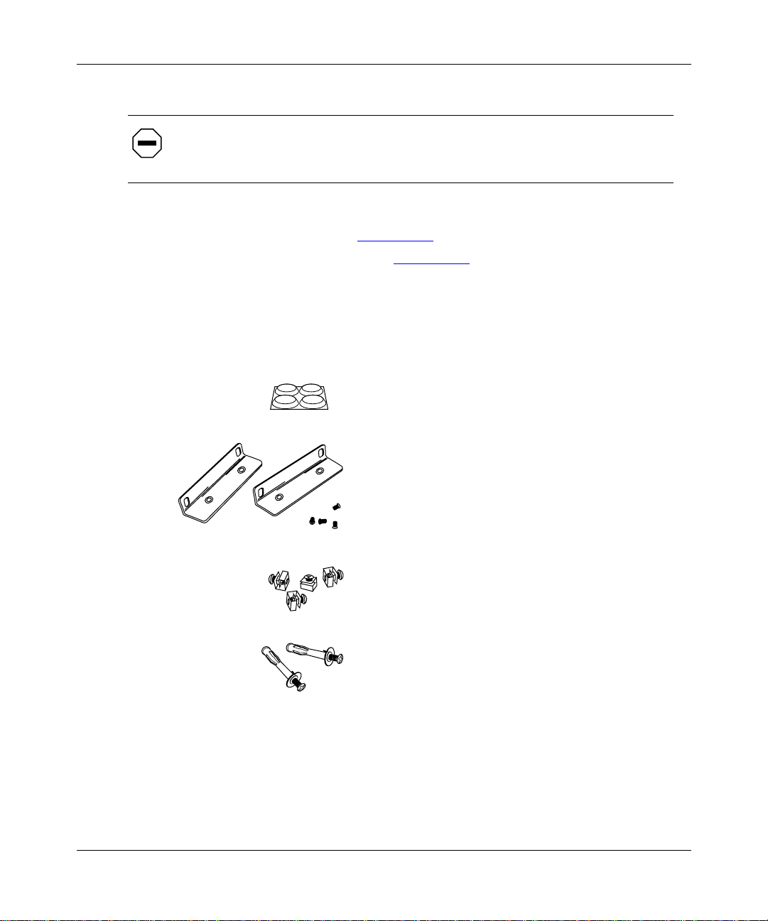
• Mounting hardware (Figure 1-1)
• Console/modem cable kit (Figure 1-2)
.
.
• Any network cables ordered with the router. If you do not have the
appropriate network cables, contact your network administrator.
• Warranty information.
• This guide.
Four rubber feet
Two flange backets
(for installing the AN in an
equipment rack or
mounting it on a wall)
1-2
Four cagenuts with screws
(for installing the AN in an
equipment rack)
2 wall anchors
(for mounting the AN on a wall)
AN0001A
Figure 1-1. M ounting Hardware
312410-A Rev 00
Page 25
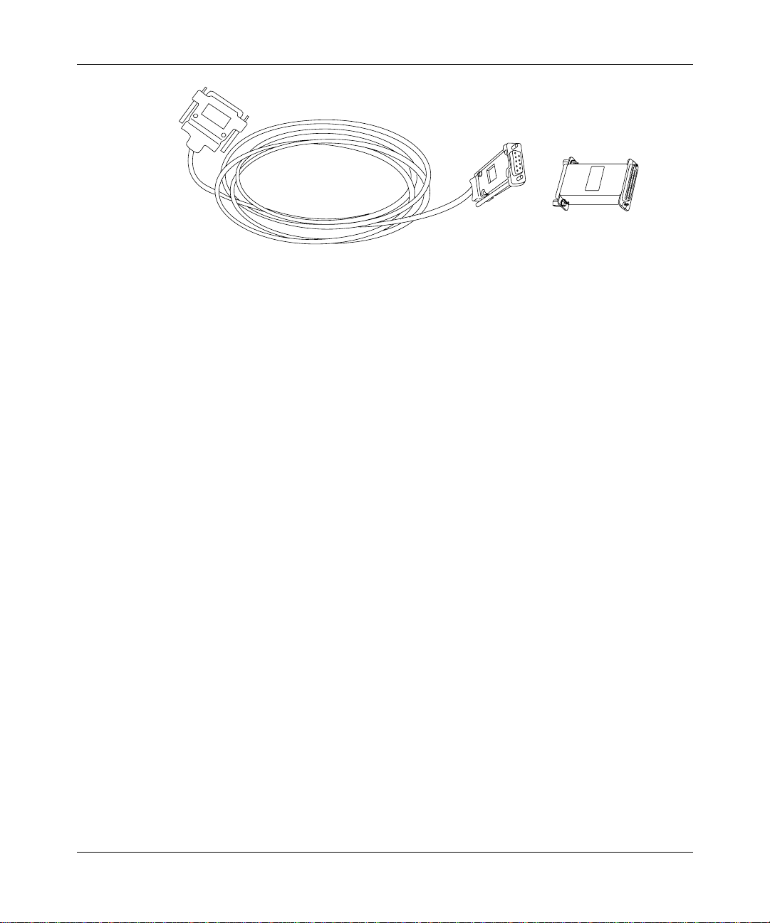
DB-9 receptacle
to DB-25 plug
serial cable
Figure 1-2. Console Cables
Supplying Tools and Equipment
You may need items that are not part of the ANH-8/DC shipping accessories.
Before installing the ANH-8/DC hardware, ensu re that you have all th e cables,
tools, and other equipment that you need at your site.
Installing the AN/DC
DB-25 receptacle
null nodem adapter
For connecting an optional terminal
or modem to the console service port
AN0002A
312410-A Rev 00
Tools
Gather the tools that you will need to set up an AN/DC at your site, such as:
• Flathead screwdriver, for attaching network cables
• Phillips screwdriver, for attaching brackets to rack- or wall-mount the AN/DC
• Electric drill, if you int end to mount the AN/DC on a wall
Cables
Unless they were specifically ordered, the Ethernet and synchronous cables
necessary for your network configuration are not part of the AN/DC shipping
accessories. If you do not have the proper cables, contact your network
administrator or see the Cable Guide for Routers and BNX Platforms.
1-3
Page 26

Installing and Operating AN/DC and ANH-8/DC Systems
Service Console
You can attach an optio nal VT-100 console or e qui v alent t o the AN/DC to moni tor
the results of startup diagnostics and perform manual boot configurations; or you
can attach any AT-compatibl e modem to allo w remote di al-in access t o diagnostic s
and configuration.
To use the Netboot, Directed Netboot, or Local Boot configuration
Note:
options (see Chapter 3), there must be a local terminal connected the first ti m e
that the ANH-8/DC powers up.
Mounting Hardware
To rack-mount the AN/DC, you need an electronic enclosure rack that meets the
following specifications:
• Heavy-duty steel construction
• Electronic Industries Association (EIA) standard hole-spacing
• Width of 19 in. (48.26 cm) and depth of 24 in. (60.96 cm)
If the rack’s rails do not have threaded holes, you must supply cagenuts to use
with the cagenut screws (see Figure 1-4
Verifying Site Requirements
Verify that your installation meet the requirements listed in this section.
• Space Requirements
• Electrical Requirements
• Environmental Requirements
The AN/DC should be installed only in dedicated equipment rooms
Note:
where access is limited to qualified service personnel.
1-4
).
312410-A Rev 00
Page 27

Installing the AN/DC
Space Requirements
The installation site must provide a certain amount of free space around the
AN/DC to dissipate hea t. Install t he AN/DC in a space that meets the fol lowing
specifications:
• Width: 19.5 in. (49.6 cm)
• Minimum depth: 15.5 in. (39.3 cm)
• Depth for servicing: 24.5 in. (62.2 cm)
Electrical Requirements
The installation site must provide an isolated power source that meets these
electrical specifications:
• Input voltage of -48.0 or -60.0 volts DC, +/- 20%
• 1.5 amperes (A) input current under full load at -38.0 VDC input
• Reinforced insulation from the main AC power
We recommend the use of #16 AWG cables between the AN/DC and the power
source to minimize voltage drop. When measuring the cable run, be certain to
include both the input and return cables.
312410-A Rev 00
Environmental Requirements
The AN/DC installation site must meet the following specifications:
• Altitude: 0 to 8,000 ft (0 to 2,438.4 m)
• Humidity: 10% to 90%, noncondensing
• Temperature: 32°F to 104°F (0°C to 40°C) stable
1-5
Page 28

Installing and Operating AN/DC and ANH-8/DC Systems
Installing the AN/DC
With a ll ca bling atta ched, you can i nstal l the AN/DC in any of the following w ays:
• Position the AN/DC on a flat, sturdy surface.
• Install th e AN/DC in an electronic enclosure rack.
• Mount the AN/DC on a wall.
The following sections provide instructions for each option. Refer to the
appropriate section when positioning your AN/DC.
Positioning the AN/DC on a Flat Surface
To position the AN/DC on a flat surface:
1.
Make sure that the surface is large enough for th e AN/DC to op erate
properly.
The surface must be sturdy enough to support the combined weight of the
AN/DC and any cables you connect.
2.
Peel the paper backing off the four rubber feet supplied with the AN/DC
and attach them to the embossed feet on the bottom of the AN/DC.
3.
Set the AN/DC in the chosen location .
You can now connect the network cables to the AN/DC. Go to the section
“Connecting Communications Cables
Installing the AN/DC in a Rack
For this procedure, you need
• Mounting hardware that came with the AN/DC shipment
• An electronic enclosure rack
• Phillips screwdriver
Note:
If the rack’s rail does not have threaded holes, you must supply and
attach four cagenuts.
1-6
,” later in t his chapter.
312410-A Rev 00
Page 29
Installing the AN/DC
To install the AN/DC in a rack:
1.
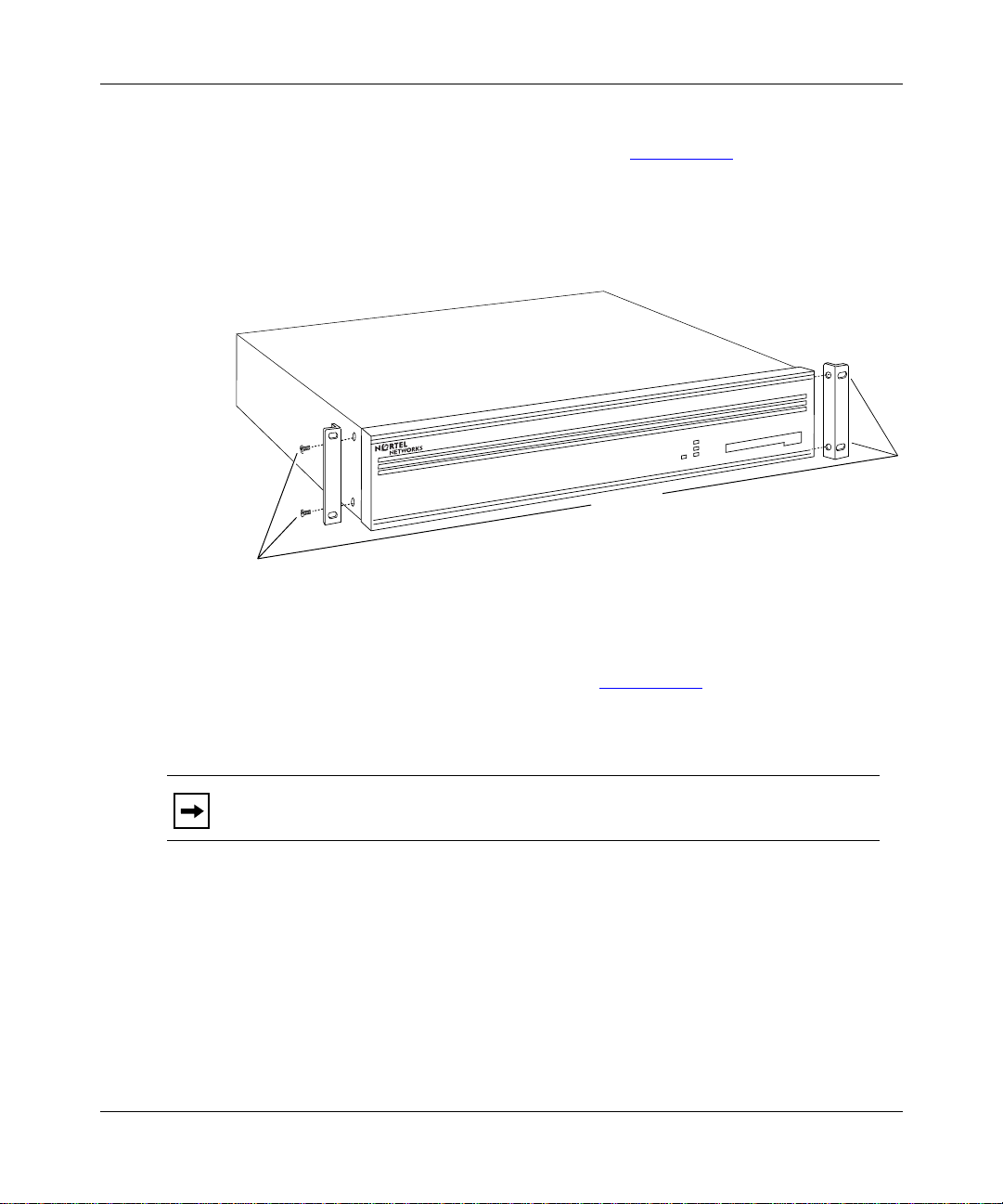
Attach each flange bracket to the AN/DC (Figure 1-3) as follows:
a.
Align the flange holes with the AN/DC mounting holes.
b.
Insert a flange screw through each flange hole and into the AN/DC.
c.
Tighten each flange screw with a Phillips screwdriver.
Run
Boot
Diag
Power
Screws
(4 places)
AN0003A
312410-A Rev 00
Figure 1-3. Att aching Flange Brackets to the AN/DC
2.
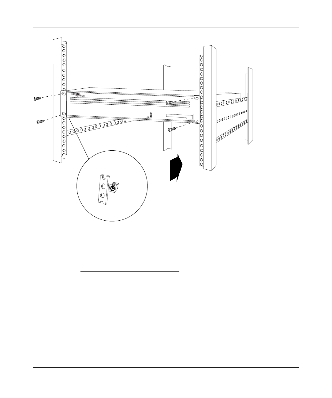
Place the AN/DC in the rack, aligning the flange holes with the holes in
the front vertical supports of the rack (Figure 1-4)
3.
Insert a cagenut screw through each flange hole and into the
.
corresponding holes in the front vertical supports of the rack.
Note:
If the rack’s rail does not have threaded holes, use the cagenuts along
with the cagenut screws. Otherwise, just use the cagenut screws.
4.
Tighten each cagenut screw with a Phillips screwdriver.
1-7
Page 30
Installing and Operating AN/DC and ANH-8/DC Systems
RUN
BOOT
POWER
DIAG
Cagenut screw
(4 places)
Rail without
threaded holes
Use cagenut
Figure 1-4. Installing the AN/DC in a Rack
You can now connect the network cables to your AN/DC. Go to the section
“Connecting Communications Cables
1-8
AN0004A
,” later in t his chapter.
312410-A Rev 00
Page 31

Mounting the AN/DC on a Wall
When mounting the AN/DC on a wall, keep the following in mind:
• Make sure th at the wall is at least 3/8 in. (0.96 cm) thick, and is made of
Sheetrock or wood.
• You need the following equipment before you start:
-- An electric drill
-- A Phillips screwdriver
-- Two wall-mount anchors
To mount the AN/DC on the wall:
1.
Drill two 5/16-in. (0.8 cm) holes in the wall 5-1/4 in. (13.34 cm) apart, at
least 3 ft. (0.915 m) off the floor.
2.
Insert one wall-mount anchor into each hole.
3.
Tighten the anchors with a Phillips screwdriver.
4.
Back the head of each screw out 1/8 in. (0.32 cm) from the wall.
Installing the AN/DC
312410-A Rev 00
5.
Hang the AN/DC on the wall by aligning the keyhole cutouts on the back
of the AN/DC with the protruding screw heads (Figure 1-5)
.
1-9
Page 32

Installing and Operating AN/DC and ANH-8/DC Systems
RUN
BOOT
DIAG
POWER
1-10
Rubber feet
AN0005A
Figure 1-5. Mounting the AN/DC on a Wall
312410-A Rev 00
Page 33

Connecting Communications Cables
To connect network cables to the back of the AN/DC:
1.
Connect the appropriate cables for your networ k configuration to the
communications ports on the back of the AN/DC (Figure 1-6)
For some cables , you may nee d a fla thead s crewdriver to secure the co nnecto r
illustrates a sample cable configur ation. Appendix C
CONSOLE
RST
COM 2
Ethernet
Transceiver
in place. Figure 1-6
describes and provides more detail on the communications ports available on
the different AN/DC models.
XCVR
UTP
TX
RX
CL
Modem,
Console
or PC Cable
P/N 1¯7913-24
S/N ATX15¯8
MODEL 22¯¯2
RLSD1RLSD2
Installing the AN/DC
TM
ACCESS NODE (AN)
This equipment complies with the requirements in part 15 of FCC rules for Class A computing device
Operation of the equipment in a residential area may cause unacceptable interference to radio and TV
reception requiring the operator to take whatever steps are nessessary to correct the interference.
COM 1
COMMUNICATIONS SERVER
.
MADE
S403
U
LISTED EDP
IN
L
EQUIPMENT
U.S.A.
L6 4490313
U
L
-48VDC
-60VDC
1.5A
RTN -VDC
ThinNet Cable
Figure 1-6. Plugging Cables into the AN/DC
2.
Connect the network cables to the physical network.
Contact your network administrator or see the Cable Guide for Routers and BNX
Platforms if you need assista nce in connecti ng the AN/DC to the phys ical netwo rk
devices, or if you are missing any network cables.
312410-A Rev 00
Synchronous
Cables
AN0089B
1-11
Page 34

Installing and Operating AN/DC and ANH-8/DC Systems
Connecting a Management Co nsole or Modem
Use t
he front-panel console port to connect an ASCII-based terminal, a personal
computer terminal emulator, or a modem to the AN/DC. Using a local terminal,
you can monitor the results of startup diagnostics and set the boot configuration.
Using an attached modem, you can allow remote dial-in access to diagnostics.
To determine whether you need to connect a console to the AN/DC, contact your
network administ rator to f in d out which sof tware co nfi guration opt ion (EZ Inst all,
Netboot, Directed Netboot, or Local Boot) is best for your site.
Refer to Chapter 2 for information on the software configuration op tions. You
must connect a console to the AN/DC to use Netboot, Directed Netboot, or Local
Boot.
Although you do not need a console or modem connection for EZ Install, we
strongly recommend that you connect a console or modem to the AN/DC. This
lets you issue commands to the AN/DC and view messages.
Note:
To use the Netboot, Directed Netboot, or Local Boot software
configuration options, you must connect a console the first time you power up
the AN/DC, as described in Chapter 3.
Complete the steps in one of the following sections:
• Connectin g a Terminal Co nsole
• Connecting a PC Console
• Connecting a Modem
Connecting a Terminal Console
To connect a console, you need both pieces in the AN/DC console/modem cable
kit (Order No. 110310) that shipped with the router (refer to Figure 1-2):
• Order No. 110307 serial console/modem cable (wit h 9-pin receptacle to
25-pin plug connectors)
• Order No. 110308 null modem crossover adapter (with two 25-pin receptacle
connectors)
1-12
312410-A Rev 00
Page 35

Installing the AN/DC
Once you have the appropriate equipment, complete the following steps:
1.
Power on and configure the console, using the parameters in Table 1-1.
Refer to the console user manual for instructions.
Table 1-1. Console Parameters
Parameter Value
Baud Rate 9600
Data Bits 8
Stop Bits 1
Parity None
2.
Power off the console.
3.
Attach the null modem crossover adapter to the 25-pin cable connector
(Figure 1-7)
4.
Insert the screws on the cable connector into the receptacle on the
.
adapter connector and tighten each screw.
312410-A Rev 00
Console cable connector
Rotate to tighten screw
Null modem crossover adapter
Screw receptacle
AN0010A
Figure 1-7. Att aching the Modem Adapter to the Console Cable
5.
Insert the 9-pin receptacle end of the console cable into the CONSOLE
port on the back panel of the AN/DC (Figure 1-8)
.
1-13
Page 36

Installing and Operating AN/DC and ANH-8/DC Systems
COMM
U
L
U
L
-48VDC
-60VDC
CONSOLE
UTPXCVR
TX
RX
CL
COM 2
RST
COM 1
RSLD1RSLD2
RTN -VDC
1.5A
20 mA PR
KB
Console Cable Plus
Null Modem Adapter
AN0011B
Figure 1-8. Connecting a Terminal Console
6.
Attach the 25-pin receptacle connect or on the combined cable and
adapter to the terminal’s host connector.
The console is now connected. Proceed to the section “Connecting to the DC
Power Source.”
Connecting a PC Console
To connect a PC, you need both pieces in the console/modem cable kit that
shipped with the router (Nortel Networks Order No. 110310):
• Order No. 110307 serial console/modem cable (wit h 9-pin receptacle to
25-pin plug connectors)
• Order No. 110308 null modem crossover adapter (with two 25-pin receptacle
connectors)
You also need another standard serial cable with a 25-pin plug connector.
1-14
312410-A Rev 00
Page 37

Installing the AN/DC
Once you have the appropriate equipment, complete the following steps:
1.
Insert the 9-pin receptacle end of the console cable into the CONSOLE
port on the AN/DC back panel (Figure 1-9)
2.
Attach the null modem crossover adapter to the other end of the console
cable (refer to Figure 1-7
3.
Attach the 25-pin receptacle end of the cable-plus-adapter to the PC
).
.
console cable’s 25-pin plug connector.
4.
Connect the complete cable unit to the communications port at the back
of the PC (Figure 1-9)
.
U
L
U
L
-48VDC
-60VDC
CONSOLE
UTPXCVR
TX
RX
CL
COM 2
RST
COM 1
RSLD1RSLD2
RTN -VDC
1.5A
Figure 1-9. Connecting a PC Console
The PC console is now connected. Proceed to the section “Connecting to the DC
Power Source.”
312410-A Rev 00
PC Cable
Null Modem Adapter
Console Cable
AN0012A
1-15
Page 38

Installing and Operating AN/DC and ANH-8/DC Systems
Connecting a Modem
A modem provides re mote access to the AN/DC for a network administrator. We
recommend that you connect a modem in case the AN/DC experiences system
problems.
Note:
Netboot, Directed Netboot, and Local Boot require a terminal or PC
console connection. After the AN/DC is on the network, you can replace the
console connection wit h a mod em conne ction. When using EZ Ins tall, you can
connect a modem to the AN/DC be fore or after you connect the AN/DC to the
network.
To connect a modem to the AN/DC, you need
• An AT (or Hayes) compatible modem
• The Order No. 110307 modem cable in the AN/DC console/modem cable kit
Do not use the Order No. 110308 null modem adapter from the AN/DC cable kit.
Once you have the appropriate equipment, complete the following steps:
1-16
1.
Configure the modem, using the parameters in Table 1-2.
Refer to the modem user manual for instructions.
Table 1-2. Modem Parameters
Modem Signal/Parameter Value
Clear To Send (CTS) On
Data Terminal Ready (DTR) Depends on the modem type. Set DTR to require
the modem to answer incoming calls.
Data Carrier Detect (DCD) * On while carrier is present (the AN/DC uses DCD
to detect modem connect and disconnect).
Data Set Ready (DSR) On
Ready to Send (RTS) Ignore
Synchronous/Asynchronous Mode Asynchronous
AutoAnswer Set on n rings with DTR active (n must be greater
than 0).
Local Character Echo Off
(continued)
312410-A Rev 00
Page 39

Installing the AN/DC
Table 1-2. Modem Parameters
(continued)
Modem Signal/Parameter Value
Supervisory Functions Off
Baud Rate 9600 (or less)
Data Bits 8
Stop Bits 1
Parity None
* The DCD signal is also called RLSD.
Caution:
is configured as described in Table 1-2
Do not connect a modem to the AN/DC until you are certain that it
. Connecting to the AN/DC with an
improperly configured modem could cause the router to fail or lose data.
2.
Power off the modem.
3.
Insert the 9-pin receptacle end of the modem cable into the back-panel
CONSOLE port of the AN/DC (Figure 1-10)
.
312410-A Rev 00
CONSOLE
UTPXCVR
TX
RX
CL
COM 2
RST
COM 1
RSLD1RSLD2
Figure 1-10. Connecting a Modem
RTN -VDC
PHONE
DIAL
(LEASE
DWR
3810
U
L
U
L
-48VDC
-60VDC
1.5A
NMS DTE
(LEASED)
3810
Modem Cable
AN0013A
1-17
Page 40

Installing and Operating AN/DC and ANH-8/DC Systems
4.
Insert the 25-pin plug at the other end of the modem cable into the
modem’s RS-232 data communications port
The modem is now connected to the AN/DC.
Next, connect the power source as described in the following section.
Connecting to the DC Power Source
.
Danger:
Due to high-energy hazards, only qualified service personnel are
permitted to connect the AN/DC to the power source.
To connect the AN/DC to the power source:
1.
Ensure that the pow er switch is in the OFF (0) position (Figure 1-11).
2.
Using a flathead screwdriver, loosen, but do not remove, the screws
beneath the terminal blocks marked -VDC and RTN (Figure 1-11)
DC Power Terminals (3)
-48VDC
-60VDC
COM 1
1.5A
RTN -VDC
.
U
L
U
L
Power Switch OFF (0)
Figure 1-11. AN/DC Power Switch and DC Terminals
1-18
AN0093A
312410-A Rev 00
Page 41

Installing the AN/DC
3.
Strip 3/8 in. (10 mm) of insulation from the end of a #16 or #18 AWG
cable.
Note:
Although #18 AWG cable is adequate, we recommend #16 AWG cable
to ensure minimal voltage drop from the power source.
4.
Insert the stripped end of the cable into the -VDC terminal block, the
minus lead (Figure 1-12)
5.
Tighten the screw beneath the -VDC terminal block to establish the
.
electrical connection.
U
L
U
L
Power Switch OFF (0)
312410-A Rev 00
-48VDC
-60VDC
COM 1
1.5A
RTN -VDC
Figure 1-12. Attaching AN/DC Power Input Cables
6.
Strip 3/8 in. (10 mm) of insulation from a #16 or #18 AWG cable.
Make certain to use the same wire gauge as that used for the minus lead.
7.
Insert the stripped end of the cable into the RTN terminal block, the plus
lead (Figure 1-12)
8.
Tighten the screw beneath the RTN terminal block to establish the
.
electrical connection.
AN0091B
1-19
Page 42

Installing and Operating AN/DC and ANH-8/DC Systems
9.
Connect an earth ground to either the leftmost terminal block or to the
grounding stud, located between the power switch and terminal
connectors (Figure 1-13)
.
If connecting to the grounding stud, use a #6 ring terminal.
Note:
Use the same wire gauge (or greater) for the earth ground as that used
for connection to the power source. That is, if connection to the power source
uses #16 AWG cable, use #16 AWG cable for the ground. If connection to the
power source uses #18 AWG cable, use #18 or #16 AWG cable for the ground.
U
L
U
L
1-20
-48VDC
-60VDC
COM 1
Earth ground options
1.5A
RTN -VDC
AN0092A
Figure 1-13. Attaching AN/DC Power and Ground Cables
10.
Before qualified service personnel connect the AN/DC to the power
source, verify that the power switch is OFF and that the AN/DC is
properly grounded.
Danger:
Once the AN/DC is connected to the power source, do not remove
the input wires. You must disconnect from the power source before removing
the AN/DC power input wires.
312410-A Rev 00
Page 43

Chapter 2
Installing the ANH-8/DC
This chapter describes how to install the ANH-8/DC.
Danger:
permitted to install the ANH-8/DC.
Topics in this chap ter include:
• Preparing for Installati on
• Installing the ANH-8/DC
• Connecting Communications Cables
• Connecting a Management Console or Modem
• Connecting to the DC Power Source
For information on how to install the AN/DC, see Chapter 1. For technical
specification s and an overview of the ANH-8/DC hardware, refer to Appendix C.
Due to high-energy hazards, only qualified service personnel are
Preparing for Install ation
To prepare for installation, complete the steps in the next sections to verify that:
• Your shipment is complete and undamaged.
• You have the proper equipment and tools.
• The installation location meets all site requirements.
312410-A Rev 00
2-1
Page 44

Installing and Operating AN/DC and ANH-8/DC Systems
Verifying Shipment Contents
Verify that the item s you recei v e match the items i n the packi ng list att ached to t he
shipping container.
1.
Inspect all items for shipping damage.
If you detect any damage, do not install the ANH-8/DC. Call the Nortel
Networks Technical Response Center.
2.
Verify that the items you received match the items in the packing list.
The packing list is usually affixed to the shipping container.
3.
Make sure that you rece ived
•One
cable kit
(Order No. 110310) for connecting an optional local
console or modem. The console/modem cable kit contains one 15- foot AT
standard molded serial cable (with DB-9 receptacle to DB-25 plug
connectors) and one null modem crossov er adapte r (with DB-25 to DB-25
receptacle connector s).
•Two
flange brackets
with four #10 cagenut screws and washers for
mounting the ANH-8/DC.
• Eight #6 Class B self-threading flathead
• Four #6 Class B self-threading roundhead
• Four press-on rubber
(for positioning the ANH-8/DC on a flat
feet
screws
(for rack-mounting).
screws
(for wall-mounting).
surface).
Figure 2-1
illustrates the ANH-8/DC shipping accessories.
2-2
312410-A Rev 00
Page 45

Installing the ANH-8/DC
Console/Modem Cable
(DB-9 Receptacle to
DB-25 Plug Cable
DB-25 Receptacle
Null Modem Adapter
Two Flange Brackets
Eight #6 Flathead Screws
Four #6 Roundhead Screws
Figure 2-1. Accessories in the ANH-8/DC Shipping Container
Supplying Tools and Equipment
You may need items that are not part of the ANH-8/DC shipping accessories.
Before installing the ANH-8/DC hardware, ensu re that you have all th e cables,
tools, and other equipment that you need at your site.
Tools
Gather the tools that you will need to set up an AN/DC at your site, such as:
• Phillips screwdriver, for attaching brackets to rack- or wall-mount the AN/DC
• Flathead screwdriver, for attaching network cables
• Electric drill, if you int end to mount the AN/DC on a wall
Four #10 Cagenut Screws and Washers
Four Rubber Feet
AN0037B
312410-A Rev 00
2-3
Page 46

Installing and Operating AN/DC and ANH-8/DC Systems
Cables
Unless they were specifically ordered, the Ethernet and synchronous cables
necessary for your network configuration are not part of the ANH-8/DC shipping
accessories. If you do not have the proper cables, contact your network
administrator or see the Cable Guide for Routers and BNX Platforms.
Service Console
You can attach an optional VT-100 console or equivalent to the ANH-8/DC to
monitor the results of startup dia gnostics and perf orm manual boot conf igura tions;
or you can attach any AT-compatible modem to allow remote dial-in access to
diagnostics and configuration.
To use the Netboot, Directed Netboot, or Local Boot configuration
Note:
options (see Chapter 3), there must be a local terminal connected the first ti m e
that the ANH-8/DC powers up.
Mounting Hardware
To rack-mount the ANH-8/DC, you need an electronic enclosure rack that meets
the following specifications:
2-4
• Heavy-duty steel construction
• Electronic Industries Association (EIA) standard hole-spacing
• Width of 19 in. (48.26 cm) and depth of 24 in. (60.96 cm)
If the rack’s rails do not have threaded holes, you must supply cagenuts
(Figure 2-2)
Figure 2-2. Sample Cagenuts and Screws for Unthreaded Rack Rails
to use with the cagenut screws.
Screw
Cagenut
AN0038A
To mount the ANH-8/DC on a wall, you need at least four wall-mount anchor
screws (see Figure 2-4
).
312410-A Rev 00
Page 47

Verifying Site Requirements
Verify that your installation meet the requirements listed in this section.
• Space Requirements
• Electrical Requirements
• Environmental Requirements
Note:
The AN/DC should be installed only in dedicated equipment rooms
where access is limited to qualified service personnel.
Space Requirements
The installation site must provide a certain amount of free space around the
ANH-8/DC to dissipate heat. Install the ANH-8/DC in a space that meets these
specifications:
• Width: 19.25 in. (48.9 cm)
• Minimum depth: 17.25 in. (43.8 cm)
• Depth for servicing: 26.25 in. (66.7 cm)
Installing the ANH-8/DC
312410-A Rev 00
Electrical Requirements
The installation site must provide an isolated power source that meets these
electrical specifications:
• Input voltage of -48.0 or -60.0 volts DC
• 1.5 amperes (A) input current under full load at -38.0 VDC input
• Reinforced insulation from the main AC power
We recommend the use of #16 AWG cables between the AN/DC and the power
source to minimize voltage drop. When measuring the cable run, be certain to
include both the input and return cables.
2-5
Page 48

Installing and Operating AN/DC and ANH-8/DC Systems
Environmental Requirements
The ANH-8/DC installation site must meet the foll owing environmental
specifications:
• Maximum Altitude: 10,000 ft (3000 m)
• Relative Humidity (Operating): 5% to 85%, noncondensing
• Maximum Humidity (Storage): 95%, noncondensing
• Operating Temperature: 41°F to 104°F (5°C to 40°C) stable
• Storage Temperature: -58°F to 113°F (-50° to 45°C)
These requirements meet IEC 721-3 Class 3K3 climatic conditions while under
operation and IEC 721-3 Class 1K3 climatic conditions while under storage.
Installing the ANH-8/DC
Once you are ready t o instal l the ANH- 8/DC in it s f inal l ocation, proceed wi th one
of the three se ctions below. You can
• Position the ANH-8/DC on a flat, sturdy, horizontal surface.
• Install the ANH-8/DC in an electronic enclosure rack.
• Mount the ANH-8/DC on a wall.
Positioning the ANH-8/DC on a Flat Surface
To position the ANH-8/DC on a flat surface:
1.
Make sure that the surface is large enough for th e ANH-8/DC to operate
properly.
The surface must be sturdy enough to support the combined weight of the
ANH-8/DC and any cables you connect.
2.
Peel the paper backing off the four rubber feet and attach them to the
bottom of the ANH-8/DC.
3.
Set the ANH-8/DC in the chosen location.
You can now connect the network cables to the ANH-8/DC. Go to the section
“Connecting Communications Cables
2-6
,” later in t his chapter.
312410-A Rev 00
Page 49

Installing the ANH-8/DC in a Rack
For this procedure, you need
• Four #10 cagenut screws and washers (shipped with the ANH-8/DC)
• Two flange brackets and eight #6 flathead screws (shipped with the
ANH-8/DC)
• A Phillips screwdriver
• An electronic enclosure rack
Note:
If the rack’s rail does not have threaded holes, you must supply and
attach four cagenuts.
To install the ANH-8/DC in a rack:
1.
Attach a flange bracket to both sides of the ANH-8/DC.
On each side of the chassis:
a.
Align the holes in the longer end of t he bracket with the mounting
holes near the front of the ANH-8/DC (Figure 2-3
Installing the ANH-8/DC
).
312410-A Rev 00
b.
Insert a #6 flathead screw through each hole and into the
ANH-8/DC.
c.
Tighten the four screws with a Phillips screwdriver.
2-7
Page 50

Installing and Operating AN/DC and ANH-8/DC Systems
Screws
(4 places)
Power
Fault
Boot
DCD1 DCD2 <LAN>
Col
Reset
AUI
DCM AUI Part
Run
Console
1234 5678
MDI-X/MDI
MDI-X
Partition
12345678
Link
Screws
(4 places)
Figure 2-3. Attaching Flange Brackets to Rack-Mount the ANH-8/DC
2.
Align the flange bracket holes with the hol es in the fr ont ve rtical supports
of the rack (Figure 2-4)
.
AN0040A
2-8
312410-A Rev 00
Page 51

Installing the ANH-8/DC
1
2
MDI-X/MDI
MDI-X
3
4
5
6
7
MDI-X
8
123
Partition
4
5
67
8
Link
Access Node Hub
Screws
(4 places)
Rail
Cagenut
If the rack rail is not threaded,
attach a cagenut (not supplied).
Figure 2-4. Installing the ANH-8/DC in an Electronic Enclosure Rack
3.
Insert a cagenut screw through each bracket hole and into the
corresponding holes in the rack.
4.
Tighten each cagenut screw with a Phillips screwdriver.
AN0041A
312410-A Rev 00
2-9
Page 52

Installing and Operating AN/DC and ANH-8/DC Systems
Mounting the ANH-8/DC on a Wall
For this procedure, you need
• Two flange brackets and four #6 roundhead screws (shipped with the
ANH-8/DC)
• Four to eight wall anchor screws (not shipped with the ANH-8/ DC)
• A Phillips screwdriver
Complete the following steps:
1.
Attach a flange bracket to both sides of the ANH-8/DC.
Note:
The sides of the ANH-8/DC incl ude scre w holes at both ends, pro viding
three ways to attach the brackets for wall-mounting. You can attach both
brackets toward the front of the ANH-8/DC, both brackets to ward the back, or
you can offset the two brackets, as shown in Figure 2-5
installation.
On each side of the chassis:
, for the most secure
a.
With the longer bracket piece lying flat, align the hole s i n the smaller
end of the bracket with two of the mounting holes on the side of the
ANH-8/DC (Figure 2-5)
b.
Insert a screw through each hole and into the ANH-8/DC.
c.
Tighten the four screws with a Phillips screwdriver.
Back of ANH
Screws
(2 places)
Figure 2-5. Attaching Flange Brackets to Wall-Mount the ANH-8/DC
2.
Place the ANH-8/DC with i nstalled brac kets agai nst the wall to determin e
the location of the anchor screws (Figure 2-6)
2-10
.
Front of ANH
.
Screws
(2 places)
Access Node Hub
AN0042A
312410-A Rev 00
Page 53

Installing the ANH-8/DC
Access Node Hub
312410-A Rev 00
AN0043A
Figure 2-6. Mounting t he ANH-8/DC on a Wall
3.
Insert two to four wall anchor screws thwrough the holes in each flange
bracket, and fasten each screw securely in the wall.
2-11
Page 54

Installing and Operating AN/DC and ANH-8/DC Systems
Connecting Communications Cables
Gather the communications equipment and cabling that you will attach to the
ANH-8/DC. If you do not have the proper cables, contact your network
administrator o r see t he Cabl e Guide for Router s and BNX Platforms. Appendix C
describes the ANH-8/DC cable interfaces.
Connecting an AUI Cable
Complete these steps to connect an Ethernet AUI transceiver cable to the front of
the ANH-8/DC:
Note:
Connecting the ANH-8/DC AUI port directly to the AUI port on an
Ethernet station viol at es IEEE 802.3 standards. The AUI port i s des ig ned on ly
for connection to a transceiver.
1.
Connect an Ether net AUI drop cable to the por t lab ele d AUI (Figure 2-7).
The cable must have a female 15-pin DSUB connector.
AUI interface
Power
Console
Fault
Reset
Boot Run DCM AUI Part
DCD1 DCD2 <LAN> Col
AUI
1 234 567 8
MDI-X/MDI
MDI-X
AUI cable
Figure 2-7. Connecting an AUI Cable
2.
Secure the AUI cable using the connector slide lock.
3.
Connect the other end of the cable to the transceiver device.
2-12
Partition
12345678
Link
AN0044A
312410-A Rev 00
Page 55

Connecting Ethernet Repeater Port UTP Cables
To connect unshielded twisted-pair (UTP) cables to the front panel 10Base-T
repeater ports, attach the UTP cables to the front-panel RJ-45 connectors
(Ethernet Repeater Ports 1-8), as shown in Figure 2-8
Ethernet repeater ports 1-8
with RJ-45 connectors
Installing the ANH-8/DC
.
Access Node Hub
UTP cables
AN0045A
Figure 2-8. Connecting Repeater UTP Cables
Using the MDI/MDI-X Switch
The ANH-8/DC front panel i nclud es an e x ter nal MDI/ MDI-X swit ch (Figure 2-9)
that allows you to change transmit and receive signals for 10Base-T repeater Port
1 from normal repeater input mode (media-dependent interface with c rossover , or
MDI-X) to repeater cascade out (media-dependent interface, or MDI)
configuration. In MDI-X mode, transmit and receive signal connections are
reversed; in MDI mode, the port transmits and receives straight-through signals
With a standard (straight-through) UTP cable in Port 1, press the switch in for
MDI operation.
With a crossover cable in P ort 1, keep the switch out for MDI-X operation.
312410-A Rev 00
2-13
Page 56

Installing and Operating AN/DC and ANH-8/DC Systems
Power
Console
Reset
Fault
Boot Run DCM AUI Part
DCD1 DCD2 <LAN> Col
AUI
1 234 5678
MDI-X/MDI
MDI-X
12345678
MDI-X/MDI
Figure 2-9. ANH-8/DC Front-Panel MDI-X/MDI Switch
Connecting the ANH-8/DC to Other Repeaters/Hubs
You can use Port 1 in MDI configura tion to connec t to a 10Base-T MDI-X port on
another router/hub/bridge device using UTP straight-through RJ-45 patch cables
(instead of a special crossover cable). You can interconnect (daisychain) as many
as four 8-Port ANH-8/DC or other hub systems.
Partition
Link
AN0056A
2-14
To determine whether you need to use a crossover cable or straight-through cable
to interconnect hub units, consider the following:
• If the Ethernet UTP ports on both hubs are in MDI mode, use a crossover
cable.
• If the UTP ports on both hubs are in MDI-X mode, use a crossover cable.
• If the UTP port on one hub is in MDI mode, and the UTP port on the other
hub is in MDI-X mode, use a straight-through cable.
312410-A Rev 00
Page 57

Installing the ANH-8/DC
When you configure a network with multiple ANH-8/DC (or other repeater/hub)
systems, you must comply with the following rules:
• Connect no more than four hubs.
• Make sure that each UTP connection is not longer than 100 meters
(109.4 yards).
• If a transceiver is connected to the AUI port, disable the SQE (signal quality
error) test function of the transceiver.
Power
Power
Fault
Power
Fault
Figure 2-10
shows three ANH-8/DC systems connected with straight-through
cables.
1 234 5678
MDI-X/MDI
1 234 5678
MDI-X/MDI
1 234 5678
MDI-X/MDI
Partition
12345678
MDI-X
Link
Port 1
to
Port 1
Partition
12345678
MDI-X
Link
Port 2
to
Port 1
Partition
12345678
MDI-X
Link
Reset
Console
Boot Run DCM AUI Part
DCD1 DCD2 <LAN> Col
AUI
Port 1
set for straight-through
connection (MDI)
Console
Fault
Reset
Boot Run DCM AUI Part
DCD1 DCD2 <LAN> Col
AUI
Port 1
set for default (crossover)
connection (MDI-X)
Reset
Console
Boot Run DCM AUI Part
DCD1 DCD2 <LAN> Col
AUI
Port 1
set for straight-through
connection (MDI)
Access Node Hub
Access Node Hub
Access Node Hub
AN0046A
Figure 2-10. Linking ANH-8/DC Systems
Figure 2-11 shows an ANH-8/DC linked with two other Ethernet hubs. A UTP
cable connects each MDI port to an MDI-X port on another hub.
312410-A Rev 00
2-15
Page 58

Installing and Operating AN/DC and ANH-8/DC Systems
ANH repeater port 1 switch
set to MDI
Power
Console
Fault
Reset
Boot Run DCM AUI Part
DCD1 DCD2 <LAN> Col
AUI
MDI-X/MDI
UTP cable
Model 810M Hub
Port 8 switch
set to MDI-X
Figure 2-11. Linking Hubs
Refer to “10Base-T Repeater Ports (ANH-8/DC only)” in Appendix C for more
information.
1 234 5678
MDI-X
UTP cable
Port 1 switch
set to MDI
Model 810M Hub
Model 810
Partition
12345678
Link
Model 810
AN0075A
2-16
312410-A Rev 00
Page 59

Connecting a Second Ethernet Interface UTP Cable
Complete these steps to connect a UTP cable to the back panel UTP-2 port.
Note:
This section does not apply unless you have upgraded the ANH-8/DC
with a Second Ethernet Interface module.
1.
Attach a UTP cable to th e back-panel RJ-45 con nector (Figure 2-12).
Installing the ANH-8/DC
-48VDC
-60VDC
1.5A
RTN -VDC
TX
RX
COL
UTP-2
COM 2COM 3/Expansion
Second Ethernet
UTP Cable Connector
Figure 2-12. Connecting a Second Ethernet Interface Cable
2.
Connect the other end of each cable to the communications device.
COM 1
AN0047B
312410-A Rev 00
2-17
Page 60

Installing and Operating AN/DC and ANH-8/DC Systems
Connecting Synchronous Cables
Connect one to three synchronous interface cables to the back of the ANH-8/DC:
1.
Locate the RS-232, RS-422, V.28, V.35, or X.21 interface cable.
See the Cable Guide for Routers and BNX Platforms.
2.
Connect the cable to the back-panel port labeled COM1, COM2, or
COM3 (Figure 2-13
Note:
Your ANH-8/DC may not have a third synchronous interface. The
COM3/Expansion port may be empty or contain another cable interface.
).
COM 2COM 3/Expansion
Synchronous Cables
COM 1
AN0048B
RTN -VDC
-48VDC
-60VDC
1.5A
Third Synchronous Interface
Cable Connector
Figure 2-13. Connecting Synchronous Cables to COM1, COM2, or COM3
Note:
The orientation of the COM3 connector is reversed from that of the
other COM ports.
3.
Secure the screws on the cable’s COM connector.
4.
Connect the remote end of each cable t o the appr opriate communic ations
equipment.
2-18
312410-A Rev 00
Page 61

Connecting an ISDN Cable
Connect an ISDN BRI cable to the back of the ANH-8/DC:
Note:
This section does not apply unless you have upgraded the ANH-8/DC
with an ISDN Basic Rate Interface module.
1.
Plug the ISDN cable into the ISDN-BRI connector (Figure 2-14).
Installing the ANH-8/DC
COM 2COM 3/Expansion
RTN -VDC
-48VDC
-60VDC
1.5A
Synchronous Cables
ISDN-BRI
ISDN BRI
Cable Connector
Figure 2-14. Connecting an ISDN BRI Cable
2.
Connect the other end of the cable to the ISDN communications device.
COM 1
AN0049B
312410-A Rev 00
2-19
Page 62

Installing and Operating AN/DC and ANH-8/DC Systems
Connecting a Management Co nsole or Modem
Use t
he front-panel console port to connect an ASCII-based terminal, a personal
computer terminal emulator, or a modem to the ANH-8/DC.
Using a local terminal, you can monitor the results of startup diagnostics and set
the boot configuration. Using an attached modem, you can allow remote dial-in
access to diagnostics.
Note:
To use the Netboot, Directed Netboot, or Local Boot software
configuration options, you must connect a console the first time you power up
the ANH-8/DC, as described in Chapter 3.
Connecting a Terminal Console
You need both pieces in the ANH-8/DC console/modem cable kit (Order No.
110310) to connect a console:
• Order No. 110307 serial console/modem cable (wit h 9-pin receptacle to
25-pin plug connectors)
2-20
• Order No. 110308 null modem crossover adapter (with two 25-pin receptacle
connectors)
Once you have the appropriate equipment, complete the following steps:
1.
Power on and configure the console, using the parameters in Table 2-1.
Refer to the console user manual for instructions.
Table 2-1. Console Parameters
Parameter Value
Baud Rate 9600
Data Bits 8
Stop Bits 1
Parity None
2.
Power off the console.
3.
Attach the null modem crossover adapter to the 25-pin cable connector.
312410-A Rev 00
Page 63

Installing the ANH-8/DC
4.
Insert the screw on the cable’s connector into the receptacle on the
adapter’s connector and tighten the screw (Figure 2-15)
.
Console cable connector
Rotate to tighten screw
Null modem crossover adapter
Screw receptacle
AN0010A
Figure 2-15. Attaching the Null Modem Adapter
5.
Attach the 25-pin receptacle connect or on the combined cable and
adapter to the console’s host connector (Figure 2-16)
COMM
20 mA PR
.
KB
Power
Fault
Boot
DCM AUI Part
Run
Reset
DCD1
AUI
DCD2 <LAN> Col
1234 5678
MDI-X/MDI
Partition
12345678
MDI-X
Link
Figure 2-16. Connecting a Terminal Console to the ANH-8/DC
312410-A Rev 00
Console cable plus
null modem adapter
AN0050A
2-21
Page 64

Installing and Operating AN/DC and ANH-8/DC Systems
6.
Insert the 9-pin receptacle end of the console cable into the ANH-8/DC
console port connector.
The console is now connected to the ANH-8/DC.
Connecting a PC Console
You need both pieces in the ANH-8 /DC console /modem cable kit to connect a PC:
• Order No. 110307 serial console/modem cable (wit h 9-pin receptacle to
25-pin plug connectors)
• Order No. 110308 null modem crossover adapter (with two 25-pin receptacle
connectors)
You also need another standard AT serial cable with a 25-pin plug connector.
Once you have the correct equipment, complete the following steps:
1.
Power on and configure the console, using the parameters in Table 2-1
and instructions in the console user manual.
2.
Power off the console.
2-22
3.
Insert the 9-pin receptacle end of the console cable into the front-panel
console port (Figure 2-17)
4.
Attach the null modem crossover adapter to the other end of the console
cable (refer to Figure 2-15
.
).
312410-A Rev 00
Page 65

Installing the ANH-8/DC
Access Node Hub
PC cable
Null modem adapter
Console cable
Figure 2-17. Connecting a PC Console to the ANH-8/DC
5.
Attach the 25-pin receptacle end of the cable-plus-adapter to the PC
console cable’s 25-pin plug connector.
6.
Connect the complete cable unit to the communications port at the back
of the PC (Figure 2-17)
.
Connecting a Modem
A modem provides remote access to the ANH-8/DC for a system administrator.
We recommend that you connect a modem in case the ANH-8/DC experiences
system problems.
To connect a modem to the ANH-8/DC, you need an AT (or Hayes) compatible
modem and the Order No. 110307 modem cable that came in the ANH-8/DC
console/modem cable kit. Do not use the Order No. 110308 nu ll modem cro ssov er
adapter in the ANH-8/DC cable kit.
312410-A Rev 00
AN0051A
2-23
Page 66

Installing and Operating AN/DC and ANH-8/DC Systems
Complete the following steps:
1.
Configure the modem, using the parameters in Table 2-2.
Refer to the modem user manual for instructions.
Table 2-2. Modem Parameters
Modem Signal/Parameter Value
Clear To Send (CTS) On
Data Terminal Ready (DTR) Depends on the modem type. Set DTR to require
the modem to answer incoming calls.
Data Carrier Detect (DCD) or RLSD On while carrier is present (the ANH-8/DC uses
DCD to detect modem connect and disconnect).
Data Set Ready (DSR) On
Ready to Send (RTS) Ignore
Synchronous/Asynchronous Mode Asynchronous
AutoAnswer Set on
than 0).
Local Character Echo Off
Supervisory Functions Off
Baud Rate 9600 (or less)
Data Bits 8
Stop Bits 1
Parity None
rings with DTR active (n must be greater
n
2-24
2.
Power off the modem.
3.
Insert the 9-pin receptacle end of the modem cable into the front-panel
console port (Figure 2-18)
Caution:
Do not connect the modem to the ANH-8/DC until you are certain
that it is configured as described in Table 2-2
.
(Step 1). Connecting to the
ANH-8/DC with an improperly configured modem could cause the router to
fail or lose data.
312410-A Rev 00
Page 67

Installing the ANH-8/DC
Access Node Hub
Modem cable
AN0052A
Figure 2-18. Connecting a Modem to the ANH-8/DC
4.
Insert the 25-pin plug at the other end of the modem cable into the
modem’s RS-232 data communications port
.
312410-A Rev 00
2-25
Page 68

Installing and Operating AN/DC and ANH-8/DC Systems
Connecting to the DC Power Source
Danger:
permitted to connect the ANH-8/DC to the power source. Ensure that the
connection is to an isolated -48 V or -60 V source (reinforced insulation from
the main [AC] power).
To connect the ANH-8/DC to the power source:
1.
2.
Due to high-energy hazards, only qualified service personnel are
Ensure that the pow er switch is in the OFF (0) position (Figure 2-19).
Using a flathead screwdriver, loosen, but do not remove, the screws on the
terminal blocks marked -VDC and RTN (Figure 2-19)
-48VDC
-60VDC
1.5A
RTN -VDC
.
2-26
Figure 2-19. ANH-8/DC Power Switch and DC Terminals
3.
Strip 3/8 in. (10 mm) of insulation from the end of a #16 or #18 AWG
cable.
Note:
Although #18 AWG cable is adequate, we recommend #16 AWG cable
to ensure minimal voltage drop from the power source.
4.
Insert the stripped end of the cable into the -VDC terminal block, the
minus lead (Figure 2-20)
5.
Tighten the screw beneath the -VDC terminal block to establish the
.
electrical connection.
312410-A Rev 00
AN0090A
Page 69

Installing the ANH-8/DC
DC power terminals (3)
-48VDC
-60VDC
1.5A
RTN -VDC
Power switch OFF (0)
Figure 2-20. Attaching the ANH-8/DC Power Input Cables
6.
Strip 3/8 in. (10 mm) of insulation from the end of a #16 or #18 AWG
cable.
Note:
Make certain to use th e same wir e gaug e as that used f or the minus lea d.
7.
Insert the stripped end of the cable into the RTN terminal block, the plus
lead (Figure 2-20)
8.
Tighten the screw beneath the RTN terminal block to establish the
.
electrical connection.
9.
Connect an earth ground wire to either the leftmost terminal block, or to
the grounding stud located between the power switch and the power
module connector (Figure 2-21)
.
We recommend using the same wire gauge (or greater) for the earth ground as
that used for connection to the power source. That is, if connection to the
power source uses #16 AWG cable, use #16 AWG cable for the ground. If
connection to the power source uses #18 AWG cable, use #18 or #16 AWG
cable for the ground.
AN0094A
312410-A Rev 00
Use a #6 ring terminal when the connecting to the grounding stud.
2-27
Page 70

Installing and Operating AN/DC and ANH-8/DC Systems
Earth Ground Options
-48VDC
-60VDC
1.5A
RTN -VDC
Figure 2-21. Attaching the ANH-8/DC Earth Ground Cable
10.
Before qualified service personnel connect the ANH-8/DC to the power
source, verify that the power switch is OFF and that the ANH-8/DC has
been properly grounded.
AN0095A
2-28
Danger:
Once the ANH-8/DC is connected to the power source, do not
remove the input wires. You must disc onnect from the power source before
removing the ANH-8/DC power input wires.
312410-A Rev 00
Page 71

Chapter 3
Starting the AN/D C and ANH-8/D C
The first time you start the AN/DC or ANH-8/DC, you complete an important
software configuration process.
Before you begin the initial sta rtup from a remote site:
1.
Coordinate with your network administrator.
The network administrator, using the manual Connecting BayStack AN and
ANH Systems to a Network or Configuring Remote Access , determines which
software configuration option is best for your site and configures the network
to support it.
2.
Install the PCMCIA Flash card supplied w ith the router.
See “Installing the Flash Memory Card
3.
For information about the software configuration methods, read the “About
Software Installa tion” section in this chapter.
4.
To begin the startup process, follow the detailed instructions in one of these
sections:
• Using EZ Install
• Using Netboot, Directed Netboot, or Local Boot
About Software Installation
To bridge and route traffic, the router needs a configuration file that is customized
for the network and a software image mad e up of executable files -- an operating
system kernel and applicat ion f iles. Nortel Net works s hips th ese f ile s on PCMCIA
Flash media.
312410-A Rev 00
” in this chapter.
3-1
Page 72

Installing and Operating AN/DC and ANH-8/DC Systems
You must complete an initial startup procedure to obtain the necessary files and
connect the AN/DC or ANH-8/ DC to the network. Getting a file o ver the network
is called network booti ng, or netbo oting. Getting a file from the router file system,
stored in Flash memory, is called local booting.
Note:
This guide explains using Site Manager software to connect the router
to a managed network. If you plan to use EZ Internetwork software to start the
AN/DC or ANH-8/DC on the network, you use the Quick2Config software.
Quick2Config is a Microsoft Windows-based appl ication that allows you to
quickly and easily create or modify configuration files for Nortel Networks
Access routers. See Configuring Y our Router Usin g the Quic k2Conf i g Tool for
information.
Boot Options
You use one of four Site Manager boot options to complete software installation:
EZ Install, Netboot, Directed Netboot, or Local Boot. Table 3-1
four options; the sections that follow provide steps for completing each option.
Table 3-1. Summary of Initial Startup Options
summarizes the
Boot
Option
EZ Install Local (Flash
Netboot Local (Flash
Source for
Router Image
memory card)
memory card)
or Network
(synchronous
or Ethernet
connection)
3-2
Source for
Config File Description and Requirements
Network
(synchronous
connection)
Network
(synchronous or
Ethernet
connection)
The default option. The router boots from local Flash
memory, then obtains its configuration file from a remote
UNIX- or DOS-based workstation that is configured as a
Boot Protocol (BootP) server. The router saves the
configuration to Flas h memor y
Requires a High-level Data Link Control (HD LC) or Frame
Relay synchronous connection.
The router locates an d obta ins s tartup files from a remote
UNIX- or DOS-based station that is confi gured as a Boo tP
server .
Requires a communications connection over an HDLC,
Frame Relay, or Ethernet interface, and a local console
connection.
.
(continued)
312410-A Rev 00
Page 73

Starting the AN/DC and ANH-8/DC
Table 3-1. Summary of Initial Startup Options
Boot
Option
Directed
Netboot
Local Boot Local Local The router boots from a local software image and generic
Source for
Router Image
Network
(synchronous
or Ethernet
connection)
Source for
Config File Description and Requirements
Network
(synchronous or
Ethernet
connection)
The router obtains all startup files f rom a remo te UNIX- or
DOS-based workstation tha t is conf igur ed as a Trivial File
Transfer Protocol (TFTP) server. You specify the IP
address of the TFTP server and the pathname of the
startup files before booting.
Requires a communications connection over an HDLC,
Frame Relay, or Ethernet interface, and a local console
connection.
startup confi guration file. You create a customized
configuration file by running an installation script.
Requires a local console connection.
(continued)
Installing the Flash Memory Card
A PCMCIA Flash memory card (Figure 3-1) provides storage capability for the
nonv ol atile f ile syst em (NVF S) in the AN/ DC and ANH-8/ DC. When yo u remo v e
a formatted memory card, the NVFS automatically re moves access to the card.
When you insert and format a card or insert an already formatted card, the NVFS
automatically provides access.
312410-A Rev 00
INSERT
AN0060A
Figure 3-1. Flash Memory Card
Before starting the router, install the Flash memory card supplied with the router
by following these steps:
3-3
Page 74

Installing and Operating AN/DC and ANH-8/DC Systems
1.
Position the card with the label facing up and the INSERT arrow
pointing toward the card receptacle.
2.
Insert the card into the receptacle.
Figure 3-2
shows how to insert the Flash memory car d in a n AN/DC tha t does
not have a Flash memory card protector installed.
Figure 3-3
3.
Gently push the card until it fits snugly into place.
shows how to insert the card in an ANH-8/DC.
If the card is new, and you did not obtain it from Nortel Networ ks, you must
format the card before attem pting to write to it. You can format the card using Site
Manager software or the
format command available with the Nortel Networks
Technician Interface. (Refer to Using Technician Interface Software for
instructions.)
Caution:
If you attempt to boot without the Flash memory card inserted, the
router will not operate.
3-4
RUN
POWER
BOOT
DIAG
AN0015A
Figure 3-2. Inserting the Flash Memory Card in the AN/DC Receptacle
312410-A Rev 00
Page 75

5
Figure 3-3. Inserting a Flash Memory Card in the ANH-8/DC Card
Using EZ Install
To use the EZ Install feature:
1.
Install the router and attached communications equipment as described
in Chapter 1 (AN/DC) or Chapter 2 (ANH-8/DC).
There must be at least one synchronous connection to one of the COM ports.
678
Receptacle
Starting the AN/DC and ANH-8/DC
Partition
12345678
Link
AN0061A
312410-A Rev 00
Although you do not need a modem or console connection for EZ Install, we
strongly recommend that you connec t a modem or console. This let s you issue
commands t o the router and view messages.
2.
Contact your network administrator to verify that the remote network is
set up so that you can start the EZ Install procedure.
3.
Be sure that the Flash memory card is installed, as described earlier in
this chapter.
4.
Supply power as described in this chapter.
As the router powers on, it begins diagnostic tests. Your console displays the
message
*****Testing Memory***** with the amount o f memory a vailable.
Once it passes diagnostic tests, the router automatically activates and
completes EZ Install. (It gets a software image from the local file system, its
IP address from the upstream router, and a configuration file from the BootP
server.) The router then starts bridging and routing traffic.
When booting, the AN/DC and ANH-8/DC LEDs flash in a particular order.
To interpret the LED sequence and trouble shoot any potential problems, refer
to Chapter 4.
3-5
Page 76

Installing and Operating AN/DC and ANH-8/DC Systems
Using Netboot, Directed Netboot, or Local Boot
You use a command interface to the router software, the Diagnostic Monitor, for
Netbooting or Local Booting. (You can also use the Technician Interface or Site
Manager for the Directed Netboot procedure.)
The AN/DC and ANH-8/DC ship wi th the config uration sourc e set to network and
the image source set to local. Using the Diagnostic Monitor, you change the
default configuration, bypassing the EZ Install pr oce ss. The Dia gnostic Monitor’s
bconfig
boot image.
Logging In to the Diagnostic Monitor
You begin the Netboot, Directed Netboot, or Local Boot process by logging in to
the Diagnostic Monitor. Complete these steps:
1.
2.
command enables you to speci fy the s ource f or the c onf igur atio n f ile and
Install the router and attached communications equipment as described
in Chapter 1 (AN/DC) or Chapter 2 (ANH-8/DC).
Power on the local management console.
3-6
3.
Insert the Flash memory card as described earlier in this chapter.
4.
Press the power switch on the back panel to the On position.
As the router powers on, your console displays the message
Memory***** with the amount of memory available.
*****Testing
Next, diagnostic software (AN Diagnostics) begins to test the router. The
console displays:
• The diagnostic software version
• Information about the hardware (model, revision, and serial numbers)
• The size of Flash memory and Dynamic Random Access Memory
(DRAM)
• The result of diagnostic tests as each test completes
Figure 3-4
shows sample output from diagnostic tests.
312410-A Rev 00
Page 77

Starting the AN/DC and ANH-8/DC
AN Diagnostics: Version - 7.xx - Wed Aug 30 16:29:38 EDT 1996
MOD ID = 0x41A (1050) Rev = 0x00 (00) S/N = 0xxxxxxxxx
Flash Card instal Memory = xMB
TYPE "?" or "h" for HELP
Test Description Status
TEST 001 SNPROM Checksum Test -------------------- PASSED
TEST 002 DIAG PROM Checksum Test ----------------- PASSED
TEST 003 OS PROM Checksum Test ------------------- PASSED
TEST 004 Memory Alignment Test ------------------- PASSED
TEST 005 Control Register 0 Test ----------------- PASSED
TEST 006 Control Register 1 Test ----------------- PASSED
TEST 007 Control Register 2 Test ----------------- PASSED
TEST 008 Control Register 5 Test ----------------- PASSED
TEST 009 Sts Registers Test ---------------------- PASSED
TEST 00A EEPROM Test (5 msec per byte write)------ BYPASS
TEST 00B Novram Battery Check -------------------- PASSED
.
.
.
AN0062A
Figure 3-4. Running Diagnostics
5.
Before diagnostics are complete, simultaneously hold down the control
and
c keys to bypass the automatic boot process.
Note:
Be sure to press Control-c before the diagnostic tests complete. To
display the AN Diagnostics login prompt, you must interrupt the power-up
sequence before the AN/DC or ANH-8/DC boots.
The AN Diagnostics login prompt appears. Refer to the top half of the screen
in Figure 3-5
.
312410-A Rev 00
3-7
Page 78

Installing and Operating AN/DC and ANH-8/DC Systems
TEST 00E Sync Port2 Int Loop TX Chain Test ------- PASSED
TEST 00F Sync Port2 Int Loop RX Chain Test -------
AN Diagnostics: Version - 6.01 - Mon July 24 07:54:00 EDT 1996
Login: Manager
AN Diagnostics: Version - 6.01 - Mon July 24 07:54:00 EDT 1996
MOD ID = 0x40D (1037) Rev = 01 S/N = 015693
Flash = 4MB Memory = 4MB
AN_DIAG>>
AN00063A
Figure 3-5. Logging In to the Diagnostic Monitor
6.
Type the following command at the login prompt and press the Return
key:
Manager
Note that you must type Manager
with an uppercase “M.”
Control-c
invoked
3-8
The Diagnostic Monitor command line prompt appears (Figure 3-5)
now using the Diagnostic Monitor.
7.
To use the Netboot, Directed Netboot, or the Local Boot option, refer to
the specific section that describes the procedure you want to use.
• Continuing with Netboot
• Continuing with Directed Netboot
• Continuing with Local Boot
312410-A Rev 00
. You are
Page 79

Continuing with Netboot
1.
Contact your network administrator to verify that the network is set up
for the Netboot procedure.
2.
Ask your network administrator (or refer to Appendix A) for the
interface configuration command to use in St ep 3. Write the command
below for reference.
ifconfig _______________________
Starting the AN/DC and ANH-8/DC
3.
Type the appropriate
ifconfig
command at the Diagnostic Monitor
prompt and pres s the Return k ey to conf igure the router’s interface to the
network.
Figure 3-6
AN_DIAG>> ifconfig xcvr1 192.32.37.125 255.255.255.224
AN_DIAG>>
Figure 3-6. Sample Interface Configuration Command
4.
Type the following command and press the Return key to verify the
shows a sample command.
configuration that you specified in Step 3:
getcfg
As Figure 3-7 shows, the
getcfg
command displays the location of the boot
image and the network configuration file, as well as the interface
configuration that you specified using the
ifconfig
command.
AN0001
312410-A Rev 00
3-9
Page 80

Installing and Operating AN/DC and ANH-8/DC Systems
AN_DIAG>> getcfg
Boot Options:
boot image=local
boot config=network
Verify
NetBoot Parameters:
XCVR1...IP=192.32.37.125, Mask=255.255.255.224
COM1....EZ-Install
COM2....EZ-Install
XCVR2...None
AN_DIAG>>
Figure 3-7. Verifying the Interface Configuration
Note:
The location of the image and configuration file is either local or
network. Local means that the an.exe or config file is stored on the router’s
local file system (Flash memory card). Network means that the an.exe or
config file is stored on a workstation loca ted across the network.
5.
If the configuration information is correct, continue to the next step.
Otherwise, reenter the correct
ifconfig
administrator if you need assistance.
6.
Type the following command and press the Return key to run the
diagnostic tests to completion and boot the AN:
AN0065A
command. Contact your network
3-10
reset
Or type boot
and press the Return key to boot the router without running the
diagnostic tests.
Figure 3-8
shows sample output from a boot
command.
312410-A Rev 00
Page 81

Starting the AN/DC and ANH-8/DC
AN_DIAG>> boot
Booting Access Node...
Starting OS Kernel for network boot...
Attempting Netboot on XCVR1
Attempting EZ-Install on COM1, using Wellfleet Pt-to-Pt
Attempting EZ-Install on COM2, using Wellfleet Pt-to-Pt
IP interface active on XCVR1, attempting BOOTP
Received BOOTP response from server 192.32.3.9 on XCVR1
Retrieving config 'config' from network. done
Found image '1:an.exe' on local file system...booting
Image is in compressed format... decompressing
Nortel Networks, Inc. and its Licensors.
Copyright 1992, 1993, 1994, 1995, 1996, 1997, 1998.
All rights reserved.
Login:
AN0018A
Figure 3-8. Netboot
Note:
If the router tries to Netboot and cannot find a software image or
configuration file, it attempts to Local boot once. If both attempts fail, the AN
Diagnostic Monitor Login prompt (
AN_DIAG>>) appears on the AN console. In
this case, you or your network administrator must troubleshoot the problem.
312410-A Rev 00
7.
When you boot the router, its LEDs flash in a particular order.
To interpret the LED sequence and trouble shoo t any potential problems, refer
to Chapter 4.
After connecting the r out er to t he n et w o rk, y ou ca n re pl ace the loc al cons ol e wit h
a modem connection to enab le remote dial-in access.
3-11
Page 82

Installing and Operating AN/DC and ANH-8/DC Systems
Continuing with Directed Netboot
Before you can use the Directed Netboot procedure, you must have already used
ifconfig
the
interface from which you plan to use Directed Netboot.
You can use the Diagnostic Monitor, Technician Interface, or Site M anager to
perform Directed Netboot. This guide assumes that you are at the router site and
are using the Diagnostic Monitor. To manage the router from a remote site, refer
to Connecting BayStack AN and ANH Systems to a Network.
To use the Directed Netboot feature:
1.
Contact your network administrator to verify that the remote network is
set up for the Directed Netboot procedure.
2.
Ask your network administrator (or refer to Appendix A) for the
appropriate boot configuration (
Write the commands below for ref erence.
bconfig image ________________________
bconfig config ________________________
command (as described in the previous section) to configure the
bconfig
) commands.
3-12
3.
At the Diagnostic Monitor prompt, enter the appropriate
bconfig
commands.
You must enter one
bconfig
command to specify the location of the sof tware
image, and anoth er to sp ecify the l oca tion of th e configuration file. Fig ure 3-9
shows sample commands.
AN_DIAG>> bconfig image network 192.32.x.x /usr/anstartup/krnl_an.exe
Done.
AN_DIAG>> bconfig config network 192.32.x.x /usr/anstartup/config
Done.
AN_DIAG
AN0019A
Figure 3-9. Specifying the Source for Directed Netboot
312410-A Rev 00
Page 83

Starting the AN/DC and ANH-8/DC
4.
Type the following command and press the Return key to verify the
configuration that you specified in Step 3 (Figure 3-10)
:
getcfg
Boot Options:
boot image=network
boot config=network
host IP address=192.32.x.x
image pathname=
“/usr/anstartup/krnl_an.exe”
config pathname=
“/usr/anstartup/config”
NetBoot Parameters:
XCVR1...IP=192.32.x.x, Mask=255.255.255.224
COM1....EZ-Install
COM2....EZ-Install
XCVR2...None
AN_DIAG>>
AN0020A
Figure 3-10. Verifying Directed Netboot Configuration
312410-A Rev 00
The Boot Options section displays the following information:
• The IP address of the server where the software image and configuration
file reside
• The pathnames of the software image and configuration file
5.
If the confi guratio n information is correct, conti nue to St ep 6. Otherw ise,
reenter the correct
bconfig
command. Contact your network
administrator if you need assistance.
6.
Type the following command and press the Return key to run the
diagnostic tests to completion and reboot:
reset
Or type
diagnostic tests. Figure 3-11
and press the Return key to boot the router without running the
boot
shows sample output during the boot process.
3-13
Page 84

Installing and Operating AN/DC and ANH-8/DC Systems
Booting Access Node...
Starting OS kernel for network boot...
Attempting Directed Netboot.
Directed Netboot using active IP interface XCVR1.
Retrieving config 'config' from network. done
Retrieving image 'krnl_an.exe' from network......done
Nortel Networks, Inc. and its Licensors.
Copyright 1992, 1993, 1994, 1995, 1996, 1997, 1998.
All rights reserved.
Login:
Figure 3-11. Directed Netboot
Note:
If the router cannot find a so ftware image or configuratio n file via
Directed Netboot, it at tempts to Local Boot once. If both attem pt s f ai l, the AN
Diagnostic Monitor Login prompt (
AN_DIAG>
case, you or your network administrator must troubleshoot the problem.
AN0070A
) appears on the consol e. I n this
3-14
After the router reboots, it gets a configuration file from a TFTP server and
loads the software image from the local file system.
The router starts bridging and routing traffic.
7.
When you boot the router, its LEDs flash in a particular order. To
interpret the LED sequence and troubleshoot any potential problems,
refer to Chapter 4.
After connecting the r outer to the n etwork, you ca n replace the console connec tion
with a modem connection to enable remote dial-in access.
312410-A Rev 00
Page 85

Continuing with Local Boot
You need to use both the Diagnosti c Monit or and th e Technician Interface t o local
boot the AN. Before starting the Local Boot procedure, ask your network
administrator for assistance in completing the Quick-Start worksheets in
Appendix B.
To use the Local Boot featur e:
1.
Contact your network administrator to verify that the network is set up
for the Local Boot procedure.
2.
At the Diagnostic Monitor prompt, type the following command and
press the Return key to configure the router to use its local
bconfig config local
3.
Type the following command and press the Return key to run the
diagnostic tests and boot the AN:
reset
Starting the AN/DC and ANH-8/DC
config
file:
Or type
boot
and press the Return key to boot the AN without running the
diagnostic tests.
Figure 3-12
shows sample output during the local boot process.
312410-A Rev 00
3-15
Page 86

Installing and Operating AN/DC and ANH-8/DC Systems
Booting Access Node...
Attempting local configuration and boot...
Configuration file '1:config' successfully loaded.
Found image '1:an.exe' on local file system...booting
Image is in compressed format... decompressing
Nortel Networks, Inc. and its Licensors.
Copyright 1992, 1993, 1994, 1995, 1996, 1997, 1998.
All rights reserved
Login:
Figure 3-12. Local Boot
Note:
If the router tries to Local Boot and cannot get a software image, it
attempts to Netboot on ce. If both the Local Boot an d Ne tboot atte mpts fa il, the
AN Diagnostic Monitor Login prompt appe ars on the console . In this case, you
or your network administrator must troubleshoot the problem.
AN0071A
3-16
4.
When you boot the router, its LEDs flash in a particular order. To
interpret the LED sequence and troubleshoot any potential problems,
refer to Chapter 4; then return to Step 5.
5.
At the login prompt, enter the following and press the Return ke y to log
in to the Technician Interface (Figure 3-13)
Manager
:
The Technician Interface prompt ([1:1]$) appears after the Te chnician
Interface mounts the local file system, as shown in Figure 3-13
. The prompt
indicates the present working directory.
312410-A Rev 00
Page 87

Starting the AN/DC and ANH-8/DC
Nortel Networks, Inc. and its Licensors.
Copyright 1992, 1993, 1994, 1995, 1996, 1997, 1998.
All rights reserved.
Login: Manager
Mounting new volume...
Device label:
Directory: 1:
New Present Working Directory: 1:
Welcome to the Backbone Technician Interface
[1:1]$
AN0024A
Figure 3-13. Logging In to the Technician Interface and Mounting a
Volume
312410-A Rev 00
Note:
To check the cont ents of the r outer’s local file system on the installed
Flash memory card, type
dir and press the Return key. The router software
image and config file should appear among the files listed.
6.
Type the following command and press the Return key to begin the
Quick-Start procedure:
run install.bat
7.
Using your completed Quick-Start worksheet from Appendix B, enter the
appropriate network information as the prompts appear.
The router uses this information to configure its interface to the network.
Refer to Appen dix B for sample Quick-Start screen output and for
information on using Quick-Start commands.
After the router creates and tests the configuration, your screen displays a
message saying that the Quick-Start installation is complete. Then the router
dynamically starts us ing the configuration information you entered.
3-17
Page 88

Installing and Operating AN/DC and ANH-8/DC Systems
8.
When the Technician Interface prompt reappears, type the following
command and press the Return key to exit the Technician Interface:
logout
Once the install script completes, the router starts bridging and routing traffic.
Note:
If the router tries to Local Boot and cannot get a software image, it
attempts to Netboot on ce. If both the Local Boot an d Ne tboot atte mpts fa il, the
AN Diagnostic Monitor Login prompt appears on the cons ole. In this case, you
or your network administrator must troubleshoot the problem.
9.
When you boot the router, its LEDs flash in a particular order. To
interpret the LED sequence and troubleshoot any potential problems,
refer to Chapter 4.
After configuring the router network interface, you can replace the console
connection with a modem connection to enable remote dial-in access.
3-18
312410-A Rev 00
Page 89

Chapter 4
Operating the AN/DC and ANH-8/DC
This chapter describes
• Ensuring a Successful Installation
• Checking the status of the router using
-- AN/DC LED Descriptions
-- ANH-8/DC LED Descriptions
• Powering On and Off
• Resetting the AN/DC or ANH-8/DC
• Removing a Flash Memory Card
• Protecting Memory Card Files
(using the front-panel LEDs)
312410-A Rev 00
4-1
Page 90
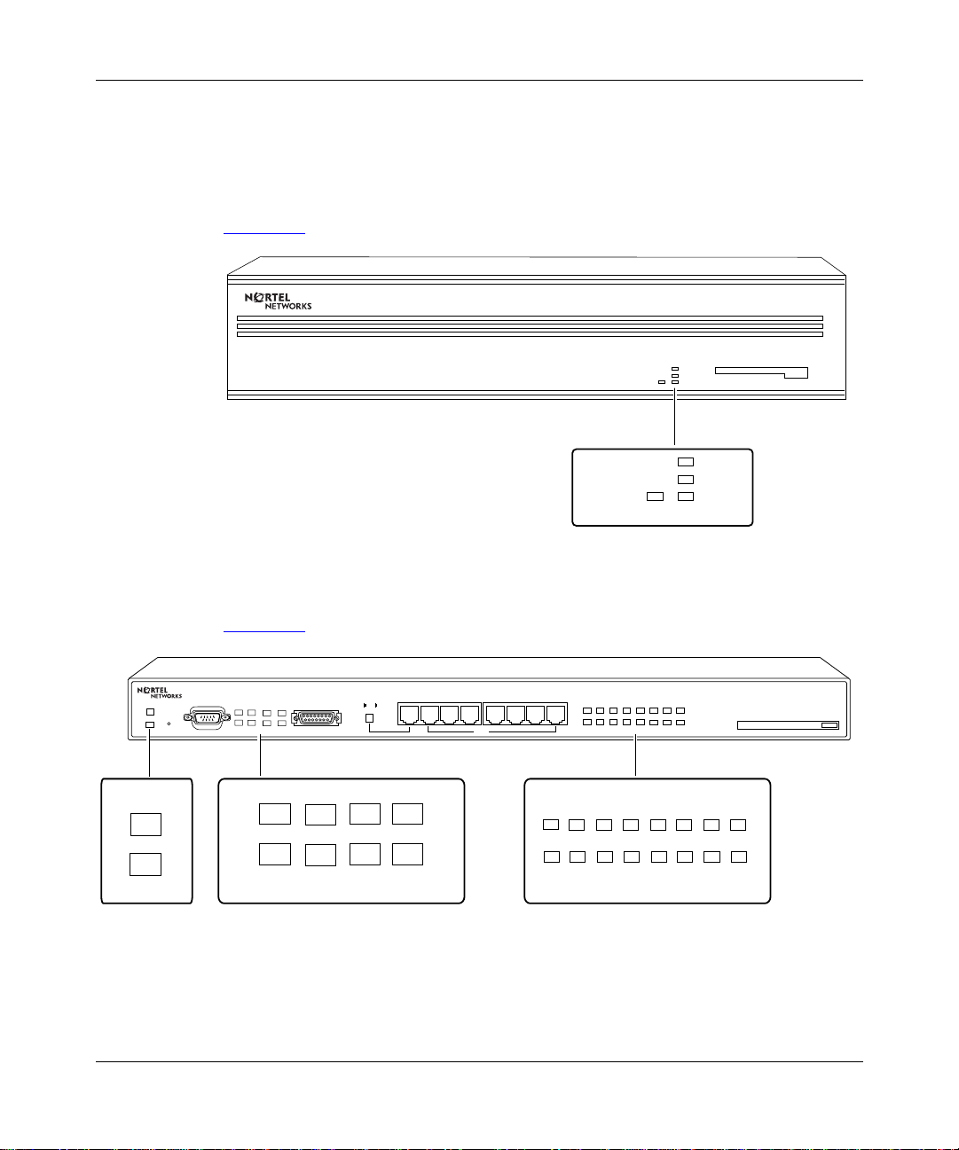
Installing and Operating AN/DC and ANH-8/DC Systems
Ensuring a Successful Installation
After connecting the router to the network, you can ensure a successful
installation by checking the LEDs on the front panel.
Power
Fault
Reset
Figure 4-1
shows the front-panel LEDs on an AN/DC.
POWER
Figure 4-1. AN/DC Front-Panel LEDs
Figure 4-2 shows the front-panel LEDs on an ANH-8/DC.
Console
Boot Run DCM AUI Part
DCD1 DCD2 <LAN> Col
AUI
1 234 5678
MDI-X/MDI
MDI-X
12345678
Partition
Link
POWER
RUN
BOOT
DIAG
RUN
BOOT
DIAG
AN0025A
Power
Boot Run DCM AUI Part
Fault
DCD1 DCD2 <LAN> Col
Figure 4-2. ANH-8/DC Front-Panel LEDs
4-2
LEDS
Partition
1 2 3 4 5 6 7 8
Link
AN0058A
312410-A Rev 00
Page 91

Operating the AN/DC and ANH-8/DC
When power is supplied to the router, the following LED sequence should occur:
• The POWER LED li ghts and remains on.
• RUN, BOOT, and DIAG (or FAULT for ANH) LEDs light for approximat ely
1 second, then turn off, indicating that the router is functioning.
• The RUN LED blinks for 1 to 3 minutes, indicating that the diagnostic tests
are running. (It blinks quickly during the initial 17-second memory test, then
slows down during the interface tests.)
• The BOOT LED lights for 1 to 3 minutes, indicating that the diagnostic tests
were successful and the router is booting.
• The RUN LED lights and the BOOT LED turns off, indicating that the router
is operational.
If the LEDs on the router light in this sequence, your installation is successful.
Contact your network administrator to verify that the router is now connected to
the network.
If the LEDs do not light in this sequence, your network administrator can refer to
Connecting BayStac k AN a nd ANH Systems to a Network to help troubleshoot the
problem. If you need additional assistance, contact your local Nortel Networks
Technical Response Center.
312410-A Rev 00
4-3
Page 92

Installing and Operating AN/DC and ANH-8/DC Systems
AN/DC LED Descriptions
LEDs on the AN/DC front and back panels provide information about how the
AN/DC is operating. The following sections describe the AN/DC front- and
back-panel LEDs. For in formation on the ANH-8/DC LEDs, se e ANH-8/DC LED
Descriptions.
Front-Panel LEDs
Table 4-1 describes the AN/DC front-panel LEDs. The se LEDs ind icate the status
of the AN/DC itself. All front-panel LEDs light briefly when the AN/DC first
receives power.
Table 4-1. Front-Panel LEDs
LED Meaning
POWER Lights and remains on when the AN/DC is receiving power.
RUN Blinks for 1 to 3 minutes, indicating that diagnostic tests are running.
When it lights again and remains lit, the AN/DC is operational.
BOOT Lights for 1 to 3 minutes, indicating that diagnostic tests were
successful and the AN/DC is booting.
DIAG Lights and remains lit when diagnostic failure occurs.
4-4
312410-A Rev 00
Page 93

Back-Panel LEDs
The LEDs on the AN/DC back-panel differ depending on the AN/DC model that
you have. Table 4-2
LEDs indicate the status of the AN/DC’s network connections.
Table 4-2. Back-Panel LEDs
LED Meaning
Ethernet/Second Ethernet interface (XCVR or UTP)
TX (Transmit) Lights when the AN/DC is transmitting data over the network.
RX (Receive) Lights when the AN/DC is receiving data from the networ k.
CL (Collision) Lights when the AN/DC detects a collision on the network.
Synchronous interfaces (COM1 and COM2)
RLSD1
(Received Line
Signal Detection 1)
RLSD2
(Received Line
Signal Detection 2)
ISDN/BRI interfaces
ISDN BRI Lights when S/T interface is active; turns off when interface is
Operating the AN/DC and ANH-8/DC
describes all of t he a v aila ble AN/DC back- panel LEDs. These
Lights when Received Line Signal Detection is active on
COM 1.
Lights when Received Line Signal Detection is active on
COM 2.
inactive.
312410-A Rev 00
4-5
Page 94

Installing and Operating AN/DC and ANH-8/DC Systems
ANH-8/DC LED Descriptions
LEDs on the ANH-8/DC front and back pa nels pro vide i nformatio n about ho w th e
ANH-8/DC is operating.
Front-Panel LEDs
Figure 4-2 sho wn earl ier illust rates t he three s ets of st atus LEDs on the ANH f ront
panel. Table 4-3
Note:
All front-panel LEDs light briefly when you turn on the ANH-8/DC;
this simply indicates that the ANH-8/DC is receiving power.
Table 4-3. ANH-8/DC Front-Panel LEDs
LED Label Color Meaning
Power Green Lights after DC power is delivered to internal circuitry
Fault Amber Lights briefly when the ANH-8/DC is powered on.
describes the function of each front-panel LED.
and remains on while the ANH-8/DC is powered on.
Remains on if a diagnostic failure occurs.
4-6
If the Run LED is also on, indica tes that the ANH-8/DC
is running its self-test.
Boot Green Lights for 1 to 3 minutes while the ANH-8/DC is
booting to indicate that diagnostic tests were
successful after power up.
Run Green Flashes for 1 to 3 minutes while diagnostic tests are
running; this indicates that the ANH-8/DC has not yet
started to execute the run-time image software code.
The light remains on to indicate that the ANH-8/DC
has begun to execute the software image.
If the Fault LED is also on, this indicates that the
ANH-8/DC is running its self-test.
DCM Green Lights to indicate an RMON data collection module
(DCM) is installed.
(continued)
312410-A Rev 00
Page 95

Operating the AN/DC and ANH-8/DC
Table 4-3. ANH-8/DC Front-Panel LEDs
LED Label Color Meaning
AUI Part
(Partition)
DCD1 (Data Carrier
Detect 1)
DCD2 (Data Carrier
Detect 2)
<LAN> Green Lights after each data transmission to indicate data
Col
(Collision)
Back-Panel LEDs
Figure 4-3 illustrates the back-panel LEDs for the ISDN and Second Ethernet
options. These LEDs are visible after installing either an ISDN BR Interface or
Second Ethernet Interface upgrade module.
(continued)
Amber Lights to indicate that the AUI port has been
partitioned from the repeater due to a disruption in
transmission. Autopartitioning occurs after an
excessive number of consecutive collisions or an
excessively long single-collision signal.
Green Lights to indicate that the first synchronous port
(COM1) is active.
Green Lights to indicate that the second synchronous port
(COM2) is active.
present in the repeater. The signal is longer than the
duration of data, allowing the eye to perceive the
occurrence of very short transmissions. The LED may
appear to flicker during numerous transmissions.
Amber Lights to indicate a collision in the AUI repeater.
312410-A Rev 00
-48VDC
-60VDC
1.5A
RTN -VDC
TX
RX
COL
ISDN-BRI
UTP-2
3 LEDs1 LED
Figure 4-3. ANH-8/DC Back-Panel LEDs
COM 2COM 3/Expansion
COM 1
AN0059B
4-7
Page 96

Installing and Operating AN/DC and ANH-8/DC Systems
Table 4-4 describes the back-panel LEDs.
Table 4-4. Back-Panel LEDs
LED Color Meaning
Ethernet UTP2 interface
TX (Transmit) Green Lights when the ANH-8/DC is transmitting data over
the network.
RX (Receive) Green Lights when the ANH-8/DC is receiving data from the
network.
COL (Collision) Amber Lights when the ANH-8/DC detects a collision on the
network.
ISDN/BRI interfaces
ISDN BRI Green Lights when S/T interface is active; turns off when
interface is ina c tive.
Powering On and Off
The DC power switch allo ws yo u to restart the rout er without ha ving to disconne ct
the power supply wires. When the power switch is turned off, the outputs of the
power supply shut off, but the front end is still active.
4-8
Danger:
Once the AN/DC is co nnec te d t o the power source, the cent ral office
must shut off the circuit breaker to remove the wires to the power supply.
To power on an AN/DC or ANH-8/DC:
1.
Press the power switch to the On position (1); that is, toggle the switch
down.
For the AN/DC, see Figure 4-4
Note:
If the AN/DC or ANH-8/DC does not power on, check the polarity of
. For the ANH-8/DC, see Figure 4-5.
the connections to the power source. If polarity has been reversed, the router
will not power on. If po larity is correct and the AN/DC or ANH-8/DC does not
power on, contact the Nortel Networks Technical Response Center.
312410-A Rev 00
Page 97

Operating the AN/DC and ANH-8/DC
U
L
U
L
-48VDC
-60VDC
COM 1
1.5A
RTN -VDC
Power switch OFF (0)
AN0091A
Figure 4-4. AN/DC Power Switch
Power switch
Figure 4-5. ANH-8/DC Power Switch
2.
Verify that air is flow i ng by placing your hand to the side of the fan vents.
Note:
If you cannot feel air flow from the vents, and the POWER and DIAG
LEDs do not light or the DI A G LED doe s not turn of f, turn t he po wer sw itch to
the OFF position. Wait one minute and then turn the power switch to the ON
position. If the problem persists, contact the Nortel Networks Technical
Response Center.
To power off, press the switch to the Off position (0); toggle the switch up.
312410-A Rev 00
COM 2COM 3/Expasion
COM 1
AN0054A
4-9
Page 98

Installing and Operating AN/DC and ANH-8/DC Systems
Resetting the AN/DC or ANH-8/DC
Yo
u can use the Reset but ton to r eboot th e router hardw are wit hout c ycl ing power,
as follows:
•To
warm-boot
the router (no diagnostic tests run), press the Reset button for
less than 3 seconds.
•To
cold-boot
the router (diagnostic tests run), press the Reset button for more
than 3 seconds.
To activate th e Reset button, use a small pointed object (for e xampl e, a pape r clip )
to press the button.
4-10
312410-A Rev 00
Page 99

AN/DC Reset Switch
On the AN/DC, the Reset button is located on the back panel of the AN/DC
(Figure 4-6)
labeled “RLSD2.”
XCVR
Operating the AN/DC and ANH-8/DC
. Labeled “RST,” it resides between the console port and the LED
U
L
U
L
-48VDC
-60VDC
RTN -VDC
1.5A
UTP
CONSOLE
TX
RX
CL
RST
COM 2
RLSD1RLSD2
COM 1
Figure 4-6. AN/DC Reset Button
ANH-8/DC Reset Switch
On an ANH-8/DC, the Reset button is set inside the fr ont panel (Figure 4-7).
Power
Fault
Reset
Console
Boot Run DCM AUI Part
DCD1 DCD2 <LAN> Col
AUI
Reset
Figure 4-7. ANH-8/DC Reset Button
1 234 5678
MDI-X/MDI
Reset Button
MDI-X
Partition
12345678
Link
AN0014B
AN0055A
312410-A Rev 00
Note:
The Link and Part ition LEDs for repe ater Ports 1-8 fl ash when you reset
the ANH, whether or not a port has attached cables.
4-11
Page 100

Installing and Operating AN/DC and ANH-8/DC Systems
Removing a Flash Memory Card
When you remove a formatted memory card, the NVFS automatically removes
access to the card. When you insert and format a card or insert an already
formatted card, the NVFS automatically provides access.
To remove a memory card from an AN/DC or ANH-8/DC:
1.
Press the eject button adjacent to the card receptacle on the front panel.
Figure 4-8
shows the eject button on an AN/DC. Figure 4-9 shows the eject
button on an ANH-8/DC.
Caution:
Do not remove the Flash memory card while the router is operating,
as this will interfere with current networking operations.
RUN
POWER
BOOT
DIAG
AN0026A
Figure 4-8. AN/DC Flash Memory Card Eject Button
Eject
button
4-12
Eject
button
AN0057A
Figure 4-9. ANH-8/DC Flash Memory Card Eject Button
2.
To insert another card into the receptacle, refer to “Installing the Flash
Memory Card” in Chapter 3.
312410-A Rev 00
 Loading...