

Page 1

Part No. 313071-C Rev 00
May 2006
4655 Great America Parkway
Santa Clara, CA 95054
Installing Media
Dependent Adapters for
the 8672ATME and
8672ATMM Modules
Page 2

Copyright © 2006 Nortel Networks. All Rights Reserved.
The information in this document is subject to change without notice. The
statements, configurations, technical data, and recommendations in this document
are believed to be accurate and reliable, but are presented without express or implied
warranty. Users must take full responsibility for their applications of any products
specified in this document. The information in this document is proprietary to
Nortel Networks Inc.
Trademarks
Nortel, Nortel Networks, the Nortel Networks logo, and the Globemark are
trademarks of Nortel Networks.
Statement of conditions
In the interest of improving internal design, operational function, and/or reliability,
Nortel Networks Inc. reserves the right to make changes to the products described in
this document without notice.
Nortel Networks Inc. does not assume any liability that may occur due to the use or
application of the product(s) or circuit layout(s) described herein.
EMI Compliance
Meets requirements of:
FCC Part 15, Subparts A and B, Class A
EN55022: 1998/CISPR22:1997), Class A
General License VDE 0871, Class B
(AmtsblVfg No. 243/1991, Vfg 46/1992) VCCI Class A ITE
EN55024:1998/CISPR24:1997
Caution: Use of controls or adjustments, or performance
of procedures other than those specified herein may
result in hazardous radiation exposure.
Page 3
Caution: Only qualified technicians should install this
equipment.
Place all printed circuit boards on an antistatic mat until
you are ready to install them. If you do not have an
antistatic mat, wear a discharge leash to free yourself of
static before touching any of the printed circuit boards, or
free yourself of static by touching a grounded metal
object before handling a printed circuit board.
Product Safety
Meets requirements of:
CSA 22.2 No. 950-M95/UL1950, 3rd ed.
EN60950: 1992 /A1:1993 /A2:1993 /A3:1995 /A4:
199721CFR, Chapter I
EN60825-1:1994 /A11:1996
Caution: Fiber optic equipment can emit laser or
infrared light that can injure your eyes. Never look into
an optical fiber or connector port. Always assume that
fiber optic cables are connected to a light source.
Caution: Glasfaserkomponenten können Laserlicht
bzw. Infrarotlicht abstrahlen, wodurch Ihre Augen
geschädigt werden können. Schauen Sie niemals in
einen Glasfaser-LWL oder ein Anschlußteil. Gehen
Sie stets davon aus, daß das Glasfaserkabel an eine
Lichtquelle angeschlossen is
t.
1
Page 4
Caution: L’équipement à fibre optique peut émettre
des rayons laser ou infrarouges qui risquent
d’entraîner des lésions oculaires. Ne jamais regarder
dans le port d’un connecteur ou d’un câble à fibre
optique. Toujours supposer que les câbles à fibre
optique sont raccordés à une source lumineuse.
Caution: Los equipos de fibra óptica pueden emitir
radiaciones de láser o infrarrojas que pueden dañar los
ojos. No mire nunca en el interior de una fibra óptica
ni de un puerto de conexión. Suponga siempre que los
cables de fibra óptica están conectados a una fuente
luminosa.
Caution: Le apparecchiature a fibre ottiche emettono
raggi laser o infrarossi che possono risultare dannosi
per gli occhi. Non guardare mai direttamente le fibre
ottiche o le porte di collegamento. Tenere in
considerazione il fatto che i cavi a fibre ottiche sono
collegati a una sorgente luminosa.
2
Page 5
Required Tool
These procedures require a Phillips screwdriver #1.
Introduction
The Media Dependent Adapters (MDAs) for the Nortel*
8672ATM, 8672ATME, and 8672ATMM Modules are modular
port adapters that you install on the module.
Each of these modules have two slots for MDAs. You can install
up to two of the following MDAs:
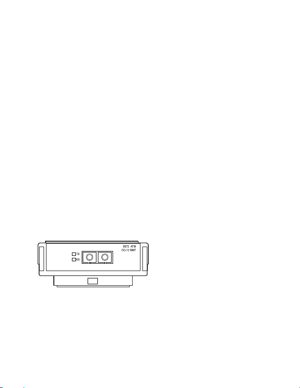
• 1-port OC-12c/STM-4 (Figure 1)
• 4-port OC-3c/STM-1 (Figure 2)
• 2-port DS-3 (Figure 3)
Figure 1 OC-12c/STM-4 MDA: 8672ATME and 8672ATMM
Modules
9725EA
3
Page 6
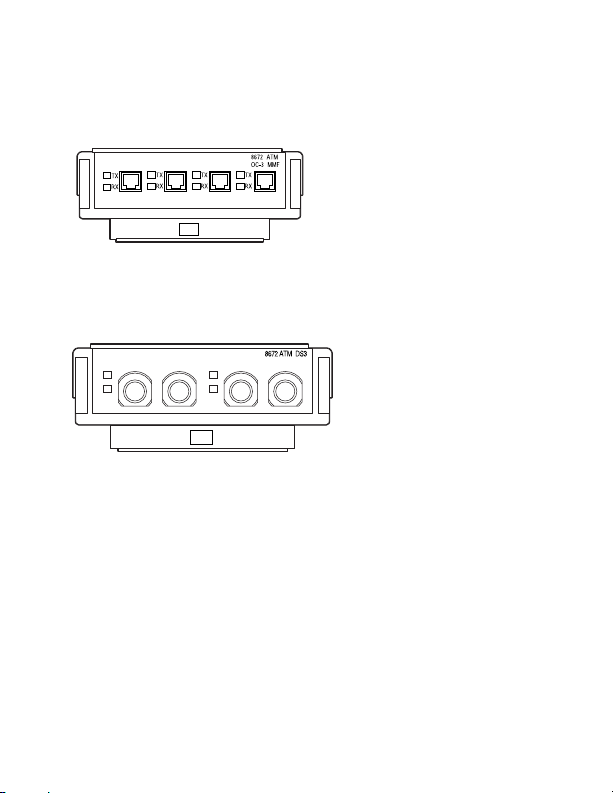
Figure 2 OC-3c/STM-1 MDA: 8672ATME and 8672ATMM
Modules
9726EA
Figure 3 DS-3 MDA: 8672ATME and 8672ATMM Modules
TX RX TX RX
TX
RX
TX
RX
10530EB
Each MDA has ports for connection to an ATM network. You can
mix types of MDAs to achieve flexibility in connectivity types.
Table 1 shows the available types of MDAs for the 8672ATM,
8672ATME, and 8672ATMM Modules.
4
Page 7
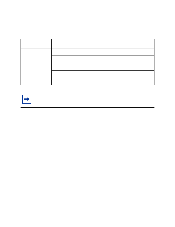
Table 1 MDAs for the 8672ATM, 8672ATME and 8672ATMM
Modules
Port type Model Cable type Connector type
OC-12c/STM-4 DS1304004 Multimode fiber Duplex SC
DS1304005 Single mode fiber Duplex SC
OC-3c/STM-1 DS1304006 Multimode fiber MT-RJ
DS1304007 Single mode fiber MT-RJ
DS-3 DS1304002 75 ohm coaxial BNC
Note: The OC-3c/STM-1 and OC-12c/STM-4 MDAs
support concatenated transmission.
The OC-3c/STM-1 and OC-12c/STM-4 MDAs for the
8672ATME and 8672ATMM Modules are class 1 laser products
as identified by the label on the MDA (
Figure 4).
5
Page 8
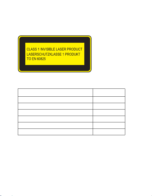
Figure 4 Product label for the 8672 ATME and 8672ATMM
Module MDA- OC-3c/STM-1 and OC-12c/STM-4
8769EB
This manual provides the following information:
Topic Page
Installing an MDA 7
Replacing an MDA 11
Connecting fiber cables 13
Connecting coaxial cables 18
MDA Specifications 19
LEDs 23
6
Page 9
Installing an MDA
Warning: You cannot hot-swap an MDA. You must
remove the 8672ATME or 8672ATMM Module, install
the MDA, and then reinstall the module. For more
information about removing and installing the
8672ATME and 8672ATMM Modules, refer to
Installing 8600 Switch Modules.
To install an MDA:
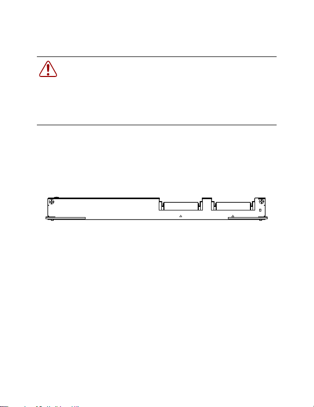
1 Lay the 8672ATME or 8672ATMM Module (Figure 5) on a
flat, static-free surface.
Figure 5 8672ATME or 8672ATMM Module
8672 ATM
OnlineMDA 2MDA 1
9898EA
2 Lift the cover out of the MDA slot by unscrewing the two
screws and lifting the cover straight up (
Figure 6). Set the
cover aside for possible future use.
7
Page 10

Figure 6 Removing the MDA slot covers
9905FA
3 Line up the MDA with the front of the 8672ATME or
8672ATMM Module, positioning the MDA so that the front
aligns with the front of the 8672ATME or 8672ATMM
Module (
Figure 7).
Figure 7 Aligning the MDA with the front of the module
MDA 1
9893FA
8
Page 11

4 Align the four holes on the MDA with the mounting posts on
the
8672ATME or 8672ATMM Module (Figure 8).
Figure 8 Aligning the MDA with the posts of the module
MDA 2
9881FA
5 Press firmly on the MDA in the middle of the back to seat the
MDA in the mounting posts on the module (
Figure 9). Apply
about 20 pounds of pressure.
Figure 9 Seating the MDA on the module
9882FA
9
Page 12

When the MDA is seated properly, the posts of the module
are visible in the holes of the MDA.
6 Insert the Phillips pan head screws through the holes
(
Figure 10). Use the #1 Phillips screwdriver to tighten the
screws.
Note: Tighten the rear screws first before you tighten the
front screws.
Figure 10 Tightening the screws
9883FA
7 For each MDA installed, attach the supplied laser product
label to the front panel of the host module, immediately
below the MDA. Use the label that is printed in the
appropriate language for the country where you are installing
the equipment.
10
Page 13

Replacing an MDA
Warning: You cannot hot-swap an MDA. You must
remove the 8672ATME or 8672ATMM Module, install
the MDA, and then reinstall the module. For more
information about removing and installing the
8672ATME and 8672ATMM Modules, refer to
Installing 8600 Switch Modules.
To replace an MDA:
1 Remove the 8672ATME or 8672ATMM Module from the
chassis and
information about removing a module from the chassis, refer
to Installing 8600 Switch Modules.
2 Using the screwdriver, unscrew the four screws from the
MDA you want to remove (
Figure 11 Preparing an MDA for removal
lay it on a flat, static-free surface. For
Figure 11).
9884FA
11
Page 14

3 Place the palm of your hand on top of the MDA, and cup
your fingers around the back of the MDA. Lift the MDA
enough to loosen it from the mounting posts (Figure 12).
Figure 12 Loosening the MDA from the mounting posts
9885FA
4 When the MDA is loosened from the mounting posts, hold
the sheet metal by each side and lift the MDA straight up,
being careful not to catch the lip of the MDA on the module
(
Figure 13). Store the MDA in a static-free container for later
use.
Figure 13 Removing the MDA from the module
MDA 2
9887FA
12
Page 15

5 Refer to “Installing an MDA” on page 7 for instructions on
installing the replacement MDA
Note: If you do not plan to install a replacement MDA,
place the slot cover on the MDA slot and tighten the 2
screws.
Connecting fiber cables
The OC-12c/STM-4 MDA uses duplex SC connectors
(Figure 14), and the OC-3c/STM-1 MDA uses
MT-RJ connectors (Figure 15).
Figure 14 OC-12c/STM-4 MDA duplex SC connector with
dust caps
9879FA
13
Page 16

Figure 15 OC-3c MDA/STM-1 MT-RJ connector with
dust
cap
9889FA
To connect fiber cables:
1 Remove the protective dust plug from the connector on the
installed MDA (
Figure 16 or Figure 17). Store the dust plug
for later use.
Figure 16 Removing the dust plug from the OC-12c/STM-4
MDA (SC) connector
MDA 1
9878FA
14
Page 17

Figure 17 Removing the dust plug from the OC-3c/STM-1
MDA (MT-RJ) connector
MDA 1
9891FA
2 Remove the protective dust caps from the connector on the
fiber cable (
Figure 18 or Figure 19). Store the dust caps for
later use.
Figure 18 Removing the dust caps from the SC fiber cable
connector
6105FB
15
Page 18

Figure 19 Removing the dust cap from the MT-RJ fiber cable
connector
9890FA
3 Hold the fiber cable connector so the keyed surface will
insert easily into the MDA connector. Carefully insert the
cable connector into the MDA connector and push gently
(
Figure 20 or Figure 21).
Figure 20 Inserting the cable connector into the
OC-12c/STM-4 MDA (SC) connector
MDA 1
9888FA
16
Page 19

Figure 21 Inserting the cable connector into the
OC-3c/STM-1 MDA (MT-RJ) connector
MDA 1
9892FA
17
Page 20

Connecting coaxial cables
The DS-3 MDA uses BNC connectors (Figure 22).
To connect a coaxial cable to a DS-3 MDA:
1 Push the coaxial cable onto the DS-3 connector (Figure 22).
Figure 22 Connecting the coaxial cable to a DS-3 MDA
10551FB
2 Turn the coaxial cable to the right until the key on the DS-3
connector clicks into the notch on the coaxial cable.
18
Page 21

MDA Specifications
The OC-3c/STM-1 MDA uses SONET STS-3c/SDH STM-1
1300 nm optical transceivers with MT-RJ fiber optic connectors
and either single mode fiber (SMF) or multimode fiber (MMF)
cabling.
Table 2 describes the 8672ATME and 8672ATMM Modules
MDA- OC-3c and OC-12c specifications.
Table 2 8672ATME and 8672ATMM Modules MDA
specifications- OC-3c/STM-1 and OC-12c/STM-4
Operating
Port type
OC-12c/STM-4 1274-1356 nm -14 to -20 dBm 622.08 Mb/s
OC-3c/STM-1 1274-1356 nm -14 to -20 dBm 155.52 Mb/s
wavelength
1260-1360 nm -8 to -15 dBm 622.08 Mb/s
1260-1360 nm -8 to -15 dBm 155.52 Mb/s
Operating
power
Pulse
repetition
rate
Note: See Table 5 for DS-3 specifications.
19
Page 22

Table 3 describes the OC-3c/STM-1 MDA 8672ATME and
8672ATMM Modules specifications.
Table 3 OC-3c/STM-1 MDA specifications: 8672ATME and
8672ATMM Modules
Parameter SMF description MMF description
Physical media 9/125 um 62.5/125 um
Line code NRZ NRZ
Wavelength 1274 to 1356 nm 1274 to 1356 nm
Average transmit
output
power
Average receiver
sensitivity
Distance 15 km 2 km
Input power 40 W 40 W
Thermal rating 138 BTU/hour maximum 138 BTU/hour maximum
-8 to -15 dBm -14 to -20 dBm
-8 to -28 dBm -14 to -30 dBm
20
Page 23

The OC-12c/STM-4 MDA uses SONET STS-3c/SDH STM-1
1300 nm optical transceivers with duplex SC-type fiber optic
connectors and either single mode fiber (SMF) or multimode
fiber (MMF) cabling.
Table 4 describes the OC-12c/STM-4
MDA 8672ATME and 8672ATMM Modules specifications.
Table 4 OC-12c/STM-4 MDA specifications: 8672ATME and
8672ATMM Modules
Parameter SMF description MMF description
Physical media 9/125 um 62.5/125 um
Line code NRZ NRZ
Wavelength 1274 to 1356 nm 1274 to 1356 nm
Average transmit
power
output
Average receiver
sensitivity
Distance 15 km 500 m
Input power 40 W 40 W
Thermal rating 138 BTU/hour maximum 138 BTU/hour maximum
-8 to -15 dBm -14 to -20 dBm
-8 to -28 dBm -14 to -26 dBm
21
Page 24

The DS-3 MDA uses a 75 ohm coaxial cable. Table 5 describes
the DS-3 MDA.
Table 5 DS-3 MDA specifications: 8672ATME and
8672ATMM Modules
Parameter Specification
Line rate 44,736 Mb/s (20 ppm)
Impedence 75 ohms
Maximum length 450 feet (135 m)
22
Page 25

LEDs
The MDAs have two bicolor LEDs on each port: one marked TX
(transmit) and one marked RX (receive).
LEDs.
Table 6 MDA LED indications
Label Color State Meaning
TX Green Steady Indicates network activity for the
corresponding port. A very low level of
network activity (approximately 1-5 pps) can
cause the LED to blink.
— Off The port is not transmitting data (no network
activity).
Amber Blinking The port is out of order; the administrative
RX Green Blinking Indicates network activity for the
Green Steady The port is operational; no network activity.
Amber Blinking The port is not operational; the administrative
Amber Steady A Remote Defect Indication (RDI)1 alarm
— Off The port is not operational (be sure that the
state is down.
corresponding port (the port is receiving
traffic).
state is down.
condition has been detected; the
administrative state is down.
MDA is fully seated in the slot; check that the
port is properly configured).
Table 6 describes the
23
Page 26

1. Remote defect indications (RDI) indicates that a failure has occurred at
the far end of the network. In ATM, when the physical layer detects loss
of signal or cell synchronization, RDI cells are used to report a VPC/
VCC failure. RDI cells are sent upstream by a VPC/VCC endpoint to
notify the source VPC/VCC endpoint of the downstream failure.
24
 Loading...