

Page 1

Part No. 312755-G Rev 00
May 2006
4655 Great America Parkway
Santa Clara, CA 95054
Installing the Breaker Interface Panel for the Ethernet Routing Switch 8010co Chassis
Page 2

2
Copyright © 2006 Nortel Networks. All Rights Reserved.
The information in this document is subject to change without notice. The statements, configurations, technical data, and
recommendations in this document are believed to be accurate and reliable, but are presented without express or implied
warranty. Users must take full responsibility for their applications of any products specified in this document. The
information in this document is proprietary to Nortel.
Trademarks
*Nortel, the Nortel logo, and the Globemark are trademarks of Nortel.
Adobe and Acrobat Reader are trademarks of Adobe Systems Incorporated.
Statement of conditions
In the interest of improving internal design, operational function, and/or reliability, Nortel Inc. reserves the right to make
changes to the products described in this document without notice.
Nortel Inc. does not assume any liability that may occur due to the use or application of the product(s) or circuit layout(s)
described herein.
International regulatory statements of conformity
This is to certify that the Nortel 8000 Series chassis and components installed within the chassis were evaluated to the
international regulatory standards for electromagnetic compliance (EMC) and safety and were found to have met the
requirements for the following international standards:
• EMC - Electromagnetic Emissions – CISPR 22, Class A
• EMC - Electromagnetic Immunity – CISPR 24
• Electrical Safety – IEC 60950, with CB member national deviations
Further, the equipment has been certified as compliant with the national standards as detailed below.
National electromagnetic compliance (EMC) statements of compliance
FCC statement (USA only)
This equipment has been tested and found to comply with the limits for a Class A digital device, pursuant to Part 15 of
the Federal Communications Commission (FCC) rules. These limits are designed to provide reasonable protection
against harmful interference when the equipment is operated in a commercial environment. This equipment generates,
uses, and can radiate radio frequency energy. If it is not installed and used in accordance with the instruction manual, it
may cause harmful interference to radio communications. Operation of this equipment in a residential area is likely to
cause harmful interference, in which case users will be required to take whatever measures may be necessary to correct
the interference at their own expense.
ICES statement (Canada only)
Canadian Department of Communications Radio Interference Regulations
This digital apparatus (8000 Series chassis and installed components) does not exceed the Class A limits for radio-noise
emissions from digital apparatus as set out in the Radio Interference Regulations of the Canadian Department of
Communications.
312755-G Rev 00
Page 3

Règlement sur le brouillage radioélectrique du ministère des Communications
Cet appareil numérique (8000 Series chassis) respecte les limites de bruits radioélectriques visant les appareils
numériques de classe A prescrites dans le Règlement sur le brouillage radioélectrique du ministère des Communications
du Canada.
CE marking statement (Europe only)
EN 55 022 statements
This is to certify that the Nortel 8000 Series chassis and components installed within the chassis are shielded against the
generation of radio interference in accordance with the application of Council Directive 89/336/EEC. Conformity is
declared by the application of EN 55 022 Class A (CISPR 22).
War nin g: This is a Class A product. In a domestic environment, this product may cause radio interference, in which
case, the user may be required to take appropriate measures.
Achtung: Dieses ist ein Gerät der Funkstörgrenzwertklasse A. In Wohnbereichen können bei Betrieb dieses Gerätes
Rundfunkstörungen auftreten, in welchen Fällen der Benutzer für entsprechende Gegenmaßnahmen verantwortlich ist.
Attention: Ceci est un produit de Classe A. Dans un environnement domestique, ce produit risque de créer des
interférences radioélectriques, il appartiendra alors à l’utilisateur de prendre les mesures spécifiques appropriées.
EN 55 024 statement
This is to certify that the Nortel 8000 Series chassis is shielded against the susceptibility to radio interference in
accordance with the application of Council Directive 89/336/EEC. Conformity is declared by the application of
EN 55 024 (CISPR 24).
3
EC Declaration of Conformity
This product conforms to the provisions of the R&TTE Directive 1999/5/EC.
VCCI statement (Japan/Nippon only)
This is a Class A product based on the standard of the Voluntary Control Council for Interference (VCCI) for
information technology equipment. If this equipment is used in a domestic environment, radio disturbance may arise.
When such trouble occurs, the user may be required to take corrective actions.
Installing the Breaker Interface Panel for the Ethernet Routing Switch 8010co Chassis
Page 4
4
Denan statement (Japan/Nippon only)
National safety statements of compliance
CE marking statement (Europe only)
EN 60 950 statement
This is to certify that the Nortel 8000 Series chassis and components installed within the chassis are in compliance with
the requirements of EN 60 950 in accordance with the Low Voltage Directive. Additional national differences for all
European Union countries have been evaluated for compliance. Some components installed within the 8000 Series
chassis may use a nickel-metal hydride (NiMH) and/or lithium-ion battery. The NiMH and lithium-ion batteries are
long-life batteries, and it is very possible that you will never need to replace them. However, should you need to replace
them, refer to the individual component manual for directions on replacement and disposal of the battery
Nortel Inc. software license agreement
This Software License Agreement (“License Agreement”) is between you, the end-user (“Customer”) and Nortel
Corporation and its subsidiaries and affiliates (“Nortel”). PLEASE READ THE FOLLOWING CAREFULLY. YOU
MUST ACCEPT THESE LICENSE TERMS IN ORDER TO DOWNLOAD AND/OR USE THE SOFTWARE. USE
OF THE SOFTWARE CONSTITUTES YOUR ACCEPTANCE OF THIS LICENSE AGREEMENT. If you do not
accept these terms and conditions, return the Software, unused and in the original shipping container, within 30 days of
purchase to obtain a credit for the full purchase price.
“Software” is owned or licensed by Nortel, its parent or one of its subsidiaries or affiliates, and is copyrighted and
licensed, not sold. Software consists of machine-readable instructions, its components, data, audio-visual content (such
as images, text, recordings or pictures) and related licensed materials including all whole or partial copies. Nortel grants
you a license to use the Software only in the country where you acquired the Software. You obtain no rights other than
those granted to you under this License Agreement. You are responsible for the selection of the Software and for the
installation of, use of, and results obtained from the Software.
1. Licensed Use of Software. Nortel grants Customer a nonexclusive license to use a copy of the Software on only
one machine at any one time or to the extent of the activation or authorized usage level, whichever is applicable. To the
extent Software is furnished for use with designated hardware or Customer furnished equipment (“CFE”), Customer is
granted a nonexclusive license to use Software only on such hardware or CFE, as applicable. Software contains trade
secrets and Customer agrees to treat Software as confidential information using the same care and discretion Customer
uses with its own similar information that it does not wish to disclose, publish or disseminate. Customer will ensure that
anyone who uses the Software does so only in compliance with the terms of this Agreement. Customer shall not a) use,
copy, modify, transfer or distribute the Software except as expressly authorized; b) reverse assemble, reverse compile,
312755-G Rev 00
Page 5

reverse engineer or otherwise translate the Software; c) create derivative works or modifications unless expressly
authorized; or d) sublicense, rent or lease the Software. Licensors of intellectual property to Nortel are beneficiaries of
this provision. Upon termination or breach of the license by Customer or in the event designated hardware or CFE is no
longer in use, Customer will promptly return the Software to Nortel or certify its destruction. Nortel may audit by remote
polling or other reasonable means to determine Customer’s Software activation or usage levels. If suppliers of third
party software included in Software require Nortel to include additional or different terms, Customer agrees to abide by
such terms provided by Nortel with respect to such third party software.
2. Warranty. Except as may be otherwise expressly agreed to in writing between Nortel and Customer, Software is
provided “AS IS” without any warranties (conditions) of any kind. NORTEL DISCLAIMS ALL WARRANTIES
(CONDITIONS) FOR THE SOFTWARE, EITHER EXPRESS OR IMPLIED, INCLUDING, BUT NOT LIMITED TO
THE IMPLIED WARRANTIES OF MERCHANTABILITY AND FITNESS FOR A PARTICULAR PURPOSE AND
ANY WARRANTY OF NON-INFRINGEMENT. Nortel is not obligated to provide support of any kind for the
Software. Some jurisdictions do not allow exclusion of implied warranties, and, in such event, the above exclusions may
not apply.
3. Limitation of Remedies. IN NO EVENT SHALL NORTEL OR ITS AGENTS OR SUPPLIERS BE LIABLE
FOR ANY OF THE FOLLOWING: a) DAMAGES BASED ON ANY THIRD PARTY CLAIM; b) LOSS OF, OR
DAMAGE TO, CUSTOMER’S RECORDS, FILES OR DATA; OR c) DIRECT, INDIRECT, SPECIAL, INCIDENTAL,
PUNITIVE, OR CONSEQUENTIAL DAMAGES (INCLUDING LOST PROFITS OR SAVINGS), WHETHER IN
CONTRACT, TORT OR OTHERWISE (INCLUDING NEGLIGENCE) ARISING OUT OF YOUR USE OF THE
SOFTWARE, EVEN IF NORTEL, ITS AGENTS OR SUPPLIERS HAVE BEEN ADVISED OF THEIR POSSIBILITY.
The forgoing limitations of remedies also apply to any developer and/or supplier of the Software. Such developer and/or
supplier is an intended beneficiary of this Section. Some jurisdictions do not allow these limitations or exclusions and, in
such event, they may not apply.
4. General
a. If Customer is the United States Government, the following paragraph shall apply: All Nortel Software
available under this License Agreement is commercial computer software and commercial computer software
documentation and, in the event Software is licensed for or on behalf of the United States Government, the
respective rights to the software and software documentation are governed by Nortel standard commercial
license in accordance with U.S. Federal Regulations at 48 C.F.R. Sections 12.212 (for non-DoD entities) and
48 C.F . R. 227.7202 (for DoD entities).
b. Customer may terminate the license at any time. Nortel may terminate the license if Customer fails to comply
with the terms and conditions of this license. In either event, upon termination, Customer must either return
the Software to Nortel or certify its destruction.
c. Customer is responsible for payment of any taxes, including personal property taxes, resulting from
Customer’s use of the Software. Customer agrees to comply with all applicable laws including all applicable
export and import laws and regulations.
d. Neither party may bring an action, regardless of form, more than two years af ter the cause of the action arose.
e. The terms and conditions of this License Agreement form the complete and exclusive agreement between
Customer and Nortel.
f. This License Agreement is governed by the laws of the country in which Customer acquires the Software. If
the Software is acquired in the United States, then this License Agreement is governed by the laws of the state
of New York.
5
Installing the Breaker Interface Panel for the Ethernet Routing Switch 8010co Chassis
Page 6

6
312755-G Rev 00
Page 7

Contents
Preface . . . . . . . . . . . . . . . . . . . . . . . . . . . . . . . . . . . . . . . . . . . . . . . . . . . . . . 15
Before you begin . . . . . . . . . . . . . . . . . . . . . . . . . . . . . . . . . . . . . . . . . . . . . . . . . . . . . 15
Text conventions . . . . . . . . . . . . . . . . . . . . . . . . . . . . . . . . . . . . . . . . . . . . . . . . . . . . . . 16
How to get Help . . . . . . . . . . . . . . . . . . . . . . . . . . . . . . . . . . . . . . . . . . . . . . . . . . . . . . 16
Chapter 1
Overview . . . . . . . . . . . . . . . . . . . . . . . . . . . . . . . . . . . . . . . . . . . . . . . . . . . . . 19
Physical description . . . . . . . . . . . . . . . . . . . . . . . . . . . . . . . . . . . . . . . . . . . . . . . . . . . 19
Front panel . . . . . . . . . . . . . . . . . . . . . . . . . . . . . . . . . . . . . . . . . . . . . . . . . . . . . . . 20
Back panel . . . . . . . . . . . . . . . . . . . . . . . . . . . . . . . . . . . . . . . . . . . . . . . . . . . . . . . 24
Accessing the alarm module . . . . . . . . . . . . . . . . . . . . . . . . . . . . . . . . . . . . . . . . . . . . 30
Configuration example . . . . . . . . . . . . . . . . . . . . . . . . . . . . . . . . . . . . . . . . . . . . . . . . . 32
7
Getting Help from the Nortel Web site . . . . . . . . . . . . . . . . . . . . . . . . . . . . . . 16
Getting Help over the phone from a Nortel Solutions Center . . . . . . . . . . . . . 17
Getting Help from a specialist by using an Express Routing Code . . . . . . . . . 17
Getting Help through a Nortel distributor or reseller . . . . . . . . . . . . . . . . . . . . 17
Shelf circuit breakers (upper and lower shelves) . . . . . . . . . . . . . . . . . . . . . . 20
Alarm module display panel . . . . . . . . . . . . . . . . . . . . . . . . . . . . . . . . . . . . . . 22
Front panel locking screws . . . . . . . . . . . . . . . . . . . . . . . . . . . . . . . . . . . . . . . 24
Shelf alarm connectors (upper and lower shelves) . . . . . . . . . . . . . . . . . . . . . 24
Central office alarms . . . . . . . . . . . . . . . . . . . . . . . . . . . . . . . . . . . . . . . . . . . . 26
Power terminal block . . . . . . . . . . . . . . . . . . . . . . . . . . . . . . . . . . . . . . . . . . . . 27
Chapter 2
Installation . . . . . . . . . . . . . . . . . . . . . . . . . . . . . . . . . . . . . . . . . . . . . . . . . . . 33
Preparing to install the breaker interface panel . . . . . . . . . . . . . . . . . . . . . . . . . . . . . . 33
Shipment contents . . . . . . . . . . . . . . . . . . . . . . . . . . . . . . . . . . . . . . . . . . . . . . . . . 34
Additional equipment . . . . . . . . . . . . . . . . . . . . . . . . . . . . . . . . . . . . . . . . . . . . . . . 35
Installing the Breaker Interface Panel for the Ethernet Routing Switch 8010co Chassis
Page 8

8 Contents
Installing the breaker interface panel . . . . . . . . . . . . . . . . . . . . . . . . . . . . . . . . . . . . . . 36
Verifying the installation . . . . . . . . . . . . . . . . . . . . . . . . . . . . . . . . . . . . . . . . . . . . . . . . 62
Chapter 3
Problem solving . . . . . . . . . . . . . . . . . . . . . . . . . . . . . . . . . . . . . . . . . . . . . . . 67
Mounting hardware . . . . . . . . . . . . . . . . . . . . . . . . . . . . . . . . . . . . . . . . . . . . . . . . 35
DC input electrical requirements . . . . . . . . . . . . . . . . . . . . . . . . . . . . . . . . . . . . . . 35
Installing the hardware . . . . . . . . . . . . . . . . . . . . . . . . . . . . . . . . . . . . . . . . . . . . . 36
Connecting cables to the chassis power supplies . . . . . . . . . . . . . . . . . . . . . . . . . 38
Routing power supply cables to the BIP . . . . . . . . . . . . . . . . . . . . . . . . . . . . . . . . 47
Connecting the ground cables to the rack grounding strip . . . . . . . . . . . . . . . . . . 48
Connecting the power supply cables to the BIP . . . . . . . . . . . . . . . . . . . . . . . . . . 49
Connecting DC input power feeds to the BIP . . . . . . . . . . . . . . . . . . . . . . . . . . . . 52
Replacing covers . . . . . . . . . . . . . . . . . . . . . . . . . . . . . . . . . . . . . . . . . . . . . . . . . . 59
Installing shelf alarm cables . . . . . . . . . . . . . . . . . . . . . . . . . . . . . . . . . . . . . . . . . 61
Initial power-up . . . . . . . . . . . . . . . . . . . . . . . . . . . . . . . . . . . . . . . . . . . . . . . . . . . 63
Verifying the LEDs . . . . . . . . . . . . . . . . . . . . . . . . . . . . . . . . . . . . . . . . . . . . . . . . . 63
Powering off the system . . . . . . . . . . . . . . . . . . . . . . . . . . . . . . . . . . . . . . . . . . . . 64
Interpreting the LEDs . . . . . . . . . . . . . . . . . . . . . . . . . . . . . . . . . . . . . . . . . . . . . . . . . . 68
Diagnosing and correcting the problem . . . . . . . . . . . . . . . . . . . . . . . . . . . . . . . . . . . . 70
Corrective actions . . . . . . . . . . . . . . . . . . . . . . . . . . . . . . . . . . . . . . . . . . . . . . . . . . . . 71
Appendix A
Technical specifications . . . . . . . . . . . . . . . . . . . . . . . . . . . . . . . . . . . . . . . . 73
Environmental . . . . . . . . . . . . . . . . . . . . . . . . . . . . . . . . . . . . . . . . . . . . . . . . . . . . . . . 73
Electrical . . . . . . . . . . . . . . . . . . . . . . . . . . . . . . . . . . . . . . . . . . . . . . . . . . . . . . . . . . .74
Physical dimensions . . . . . . . . . . . . . . . . . . . . . . . . . . . . . . . . . . . . . . . . . . . . . . . . . . . 74
Electromagnetic emissions . . . . . . . . . . . . . . . . . . . . . . . . . . . . . . . . . . . . . . . . . . . . . 74
Safety agency certification . . . . . . . . . . . . . . . . . . . . . . . . . . . . . . . . . . . . . . . . . . . . . . 74
Appendix B
BIP external cable pin assignments. . . . . . . . . . . . . . . . . . . . . . . . . . . . . . . 75
Shelf alarm connectors (J1 and J2) . . . . . . . . . . . . . . . . . . . . . . . . . . . . . . . . . . . . . . . 75
Office alarm connectors (J3 and J4) . . . . . . . . . . . . . . . . . . . . . . . . . . . . . . . . . . . . . . 77
Standalone office alarm connector (J5) . . . . . . . . . . . . . . . . . . . . . . . . . . . . . . . . . . . . 79
312755-G Rev 00
Page 9

Contents 9
Index . . . . . . . . . . . . . . . . . . . . . . . . . . . . . . . . . . . . . . . . . . . . . . . . . . . . . . . . 81
Installing the Breaker Interface Panel for the Ethernet Routing Switch 8010co Chassis
Page 10

10 Contents
312755-G Rev 00
Page 11

Figures
Figure 1 Breaker interface panel . . . . . . . . . . . . . . . . . . . . . . . . . . . . . . . . . . . . . . . 19
Figure 2 Front panel components . . . . . . . . . . . . . . . . . . . . . . . . . . . . . . . . . . . . . . 20
Figure 3 Shelf circuit breakers . . . . . . . . . . . . . . . . . . . . . . . . . . . . . . . . . . . . . . . . 21
Figure 4 Alarm module display panel . . . . . . . . . . . . . . . . . . . . . . . . . . . . . . . . . . . 22
Figure 5 Back panel components . . . . . . . . . . . . . . . . . . . . . . . . . . . . . . . . . . . . . . 24
Figure 6 Shelf alarm connections (upper and lower shelves) . . . . . . . . . . . . . . . . . 25
Figure 7 Configuring multiple BIPs to aggregate office alarms . . . . . . . . . . . . . . . . 26
Figure 8 Configuring standalone BIPs to report alarm status . . . . . . . . . . . . . . . . . 27
Figure 9 Power terminal block . . . . . . . . . . . . . . . . . . . . . . . . . . . . . . . . . . . . . . . . . 28
Figure 10 Power and grounding example . . . . . . . . . . . . . . . . . . . . . . . . . . . . . . . . . 29
Figure 11 Opening the front panel . . . . . . . . . . . . . . . . . . . . . . . . . . . . . . . . . . . . . . 30
Figure 12 Accessing the alarm module . . . . . . . . . . . . . . . . . . . . . . . . . . . . . . . . . . 31
Figure 13 Default jumper settings . . . . . . . . . . . . . . . . . . . . . . . . . . . . . . . . . . . . . . . 31
Figure 14 8010co chassis configuration with BIP option . . . . . . . . . . . . . . . . . . . . . 32
Figure 15 Contents of the BIP shipping container . . . . . . . . . . . . . . . . . . . . . . . . . . 34
Figure 16 Removing the plastic back cover from the BIP . . . . . . . . . . . . . . . . . . . . . 37
Figure 17 Installing the BIP in the rack . . . . . . . . . . . . . . . . . . . . . . . . . . . . . . . . . . . 37
Figure 18 Removing the 8010co chassis bottom 312096-A bezel . . . . . . . . . . . . . . 39
Figure 19 Location of power supplies . . . . . . . . . . . . . . . . . . . . . . . . . . . . . . . . . . . . 40
Figure 20 Loosening the power supply retaining screws . . . . . . . . . . . . . . . . . . . . . 41
Figure 21 Disconnecting the power supply from the chassis backplane . . . . . . . . . 41
Figure 22 Removing the plastic safety cover from the power supply . . . . . . . . . . . . 42
Figure 23 Power supply input and ground stud location . . . . . . . . . . . . . . . . . . . . . . 42
Figure 24 Power supply cables . . . . . . . . . . . . . . . . . . . . . . . . . . . . . . . . . . . . . . . . . 43
Figure 25 Attaching the ground lead . . . . . . . . . . . . . . . . . . . . . . . . . . . . . . . . . . . . . 43
Figure 26 Attaching the positive lead . . . . . . . . . . . . . . . . . . . . . . . . . . . . . . . . . . . . 44
Figure 27 Attaching the negative lead . . . . . . . . . . . . . . . . . . . . . . . . . . . . . . . . . . . 45
Figure 28 Replacing the plastic safety cover on the power supply . . . . . . . . . . . . . . 45
Figure 29 Replacing the power supply . . . . . . . . . . . . . . . . . . . . . . . . . . . . . . . . . . . 46
11
Installing the Breaker Interface Panel for the Ethernet Routing Switch 8010co Chassis
Page 12

12 Figures
Figure 30 Labeling cables for the BIP . . . . . . . . . . . . . . . . . . . . . . . . . . . . . . . . . . . . 47
Figure 31 Rack grounding strip example . . . . . . . . . . . . . . . . . . . . . . . . . . . . . . . . . 48
Figure 32 Attaching power supply cable leads to the BIP . . . . . . . . . . . . . . . . . . . . . 49
Figure 33 Upper and lower shelf power cables connected to the BIP . . . . . . . . . . . 50
Figure 34 Attaching the BIP ground cable . . . . . . . . . . . . . . . . . . . . . . . . . . . . . . . . 51
Figure 35 A and B feed example . . . . . . . . . . . . . . . . . . . . . . . . . . . . . . . . . . . . . . . 53
Figure 36 Locating the A and B -48 VDC input feeds . . . . . . . . . . . . . . . . . . . . . . . . 54
Figure 37 Connecting the A and B -48 VDC input feeds to the BIP (1 of 2) . . . . . . . 55
Figure 38 Connecting the A and B -48 VDC input feeds to the BIP (2 of 2) . . . . . . . 56
Figure 39 Connecting the A/B input feed returns (1 of 2) . . . . . . . . . . . . . . . . . . . . . 57
Figure 40 Connecting the A/B input feed returns (2 of 2) . . . . . . . . . . . . . . . . . . . . . 58
Figure 41 Replacing the plastic back cover on the BIP . . . . . . . . . . . . . . . . . . . . . . . 59
Figure 42 Replacing the 8010co chassis 312096-A bezel . . . . . . . . . . . . . . . . . . . . 60
Figure 43 Installing shelf alarm cables . . . . . . . . . . . . . . . . . . . . . . . . . . . . . . . . . . . 61
Figure 44 BIP LEDs and indicators . . . . . . . . . . . . . . . . . . . . . . . . . . . . . . . . . . . . . . 68
Figure 45 J1 and J2 9-pin standard D-sub connector . . . . . . . . . . . . . . . . . . . . . . . . 75
Figure 46 J1 and J2 shelf alarm connector pinouts . . . . . . . . . . . . . . . . . . . . . . . . . 76
Figure 47 J3 and J4 high-density 26-pin D-sub connector . . . . . . . . . . . . . . . . . . . . 77
Figure 48 J3 and J4 office alarm connectors . . . . . . . . . . . . . . . . . . . . . . . . . . . . . . 77
Figure 49 J5 high-density 26-pin D-sub connector . . . . . . . . . . . . . . . . . . . . . . . . . . 79
Figure 50 J5 standalone office alarm connector . . . . . . . . . . . . . . . . . . . . . . . . . . . . 79
312755-G Rev 00
Page 13

Tables
Table 1 Alarm module display LEDs . . . . . . . . . . . . . . . . . . . . . . . . . . . . . . . . . . . 22
Table 2 DC power requirements . . . . . . . . . . . . . . . . . . . . . . . . . . . . . . . . . . . . . . 35
Table 3 Single chassis and dual chassis input options . . . . . . . . . . . . . . . . . . . . . 53
Table 4 BIP LEDs and indicators . . . . . . . . . . . . . . . . . . . . . . . . . . . . . . . . . . . . . 68
Table 5 Corrective actions . . . . . . . . . . . . . . . . . . . . . . . . . . . . . . . . . . . . . . . . . . . 71
Table 6 J1 and J2 shelf alarm connector pin assignments . . . . . . . . . . . . . . . . . . 76
Table 7 J3 and J4 office alarm connector pin assignments . . . . . . . . . . . . . . . . . . 78
Table 8 J5 standalone office alarm connector pin assignments . . . . . . . . . . . . . . 80
13
Installing the Breaker Interface Panel for the Ethernet Routing Switch 8010co Chassis
Page 14

14 Tables
312755-G Rev 00
Page 15

Preface
The breaker interface panel (BIP) provides power distribution and alarm status
indications for one or two 8010co chassis in an equipment rack. The status
indications can be linked to other BIPs to provide total system status to the central
office (CO).
This guide describes how to install the breaker interface panel in an equipment
rack, connect cables, and interpret LEDs. It also includes technical specifications
for the breaker interface panel.
For a list of related publications, see the release notes that accompany your
software.
Before you begin
This guide is intended for qualified service personnel who need to install or
replace a breaker interface panel. A qualified service person must have
appropriate technical training and experience and be aware of hazards involved in
installing and replacing customer-replaceable units (CRUs).
15
Installing the Breaker Interface Panel for the Ethernet Routing Switch 8010co Chassis
Page 16

16 Preface
Text conventions
This guide uses the following text conventions:
bold Courier text
italic text Indicates new terms, book titles, and variables in
plain Courier
text
How to get Help
This section explains how to get help for Nortel products and services.
Getting Help from the Nortel Web site
Indicates command names and options and text that
you need to enter.
Example: Use the
Example: Enter
command syntax descriptions. Where a variable is two
or more words, the words are connected by an
underscore.
Example: If the command syntax is
show at <valid_route>, valid_route is one
variable and you substitute one value for it.
Indicates command syntax and system output, for
example, prompts and system messages.
Example:
Set Trap Monitor Filters
dinfo command.
show ip {alerts|routes}.
312755-G Rev 00
The best way to get technical support for Nortel products is from the Nortel
Technical Support Web site:
http://www.nortel.com/support
This site provides quick access to software, documentation, bulletins, and tools to
address issues with Nortel products. More specifically, the site enables you to:
• download software, documentation, and product bulletins
• search the Technical Support Web site and the Nortel Knowledge Base for
answers to technical issues
Page 17

Preface 17
• sign up for automatic notification of new software and documentation for
Nortel equipment
• open and manage technical support cases
Getting Help over the phone from a Nortel Solutions Center
If you don’t find the information you require on the Nortel Technical Support Web
site, and have a Nortel support contract, you can also get help over the phone from
a Nortel Solutions Center.
In North America, call 1-800-4NORTEL (1-800-466-7835).
Outside North America, go to the following Web site to obtain the phone number
for your region:
http://www.nortel.com/callus
Getting Help from a specialist by using an Express Routing Code
To access some Nortel Technical Solutions Centers, you can use an Express
Routing Code (ERC) to quickly route your call to a specialist in your Nortel
product or service. To locate the ERC for your product or service, go to:
http://www.nortel.com/erc
Getting Help through a Nortel distributor or reseller
If you purchased a service contract for your Nortel product from a distributor or
authorized reseller, contact the technical support staff for that distributor or
reseller.
Installing the Breaker Interface Panel for the Ethernet Routing Switch 8010co Chassis
Page 18

18 Preface
312755-G Rev 00
Page 19
Chapter 1
Overview
This chapter provides an overview of the BIP and covers the following topics:
• Physical description
• “Accessing the alarm module” on page 30
• “Configuration example” on page 32
Physical description
The BIP provides a central rack location where redundant input DC power feeds
are connected and routed to one or two 8010co chassis. The BIP also provides an
alarm module and display panel that monitors system components, generates
alarms, and controls LED status indicators (requires 8010co chassis configured
with an 8691SF or 8691omSF CPU Module). The alarm module provides total
system status to the central office.
19
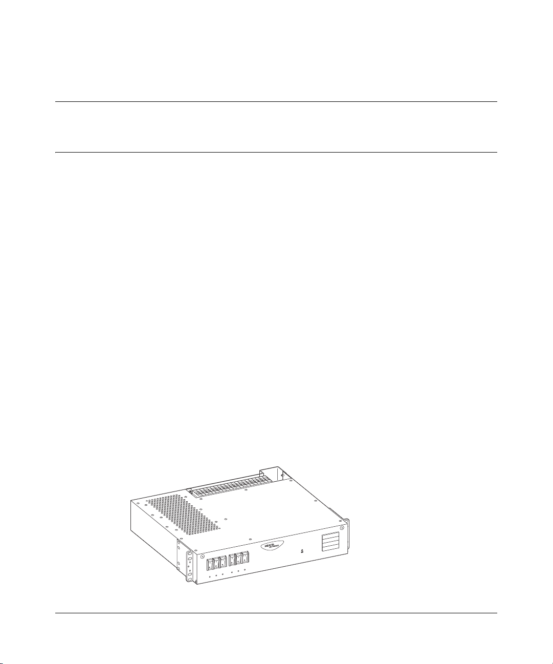
Figure 1 shows the breaker interface panel. Descriptions of the front panel
components follow the figure.
Figure 1 Breaker interface panel
R
E
W
O
P
L
A
IC
IT
R
C
R
O
J
A
M
R
O
IN
M
10370FB
Installing the Breaker Interface Panel for the Ethernet Routing Switch 8010co Chassis
Page 20
20 Chapter 1 Overview
Front panel
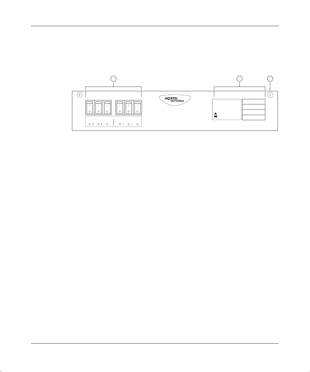
Figure 2 shows the BIP front panel components.
Figure 2 Front panel components
1 2
Upper Shelf
123 123
1 = Shelf circuit breakers (upper/lower shelves)
2 = Alarm module display panel
3 = Front-panel locking screws (x2)
Lower Shelf
Alarm Module
POWER
CRITICAL
MAJOR
MINOR
3
10376EB
Shelf circuit breakers (upper and lower shelves)
Two groups of three circuit breakers provide input power to the power supplies for
the upper and lower shelf 8010co chassis (Figure 3 on page 21):
• The first group, labeled “Upper Shelf,” provides input power to the upper
shelf power supplies.
• The second group, labeled “Lower Shelf,” provides input power to the lower
shelf power supplies.
312755-G Rev 00
If a power supply over current condition occurs, the associated circuit breaker
trips and indicates the fault by lighting the associated circuit breaker’s LED (red).
Each of the six circuit breakers is current limited to 30 amperes @80 volts direct
current. The circuit breakers are designed with internal auxiliary switches to
provide fault indications to the alarm module and to the associated circuit breaker
LEDs on the front panel. The alarm module reports circuit breaker fault conditions
by lighting the MAJOR indicator on the Alarm Module display panel.
No alarm is generated to the alarm module when the circuit breaker is manually
switched on (|) or off (O).
Page 21
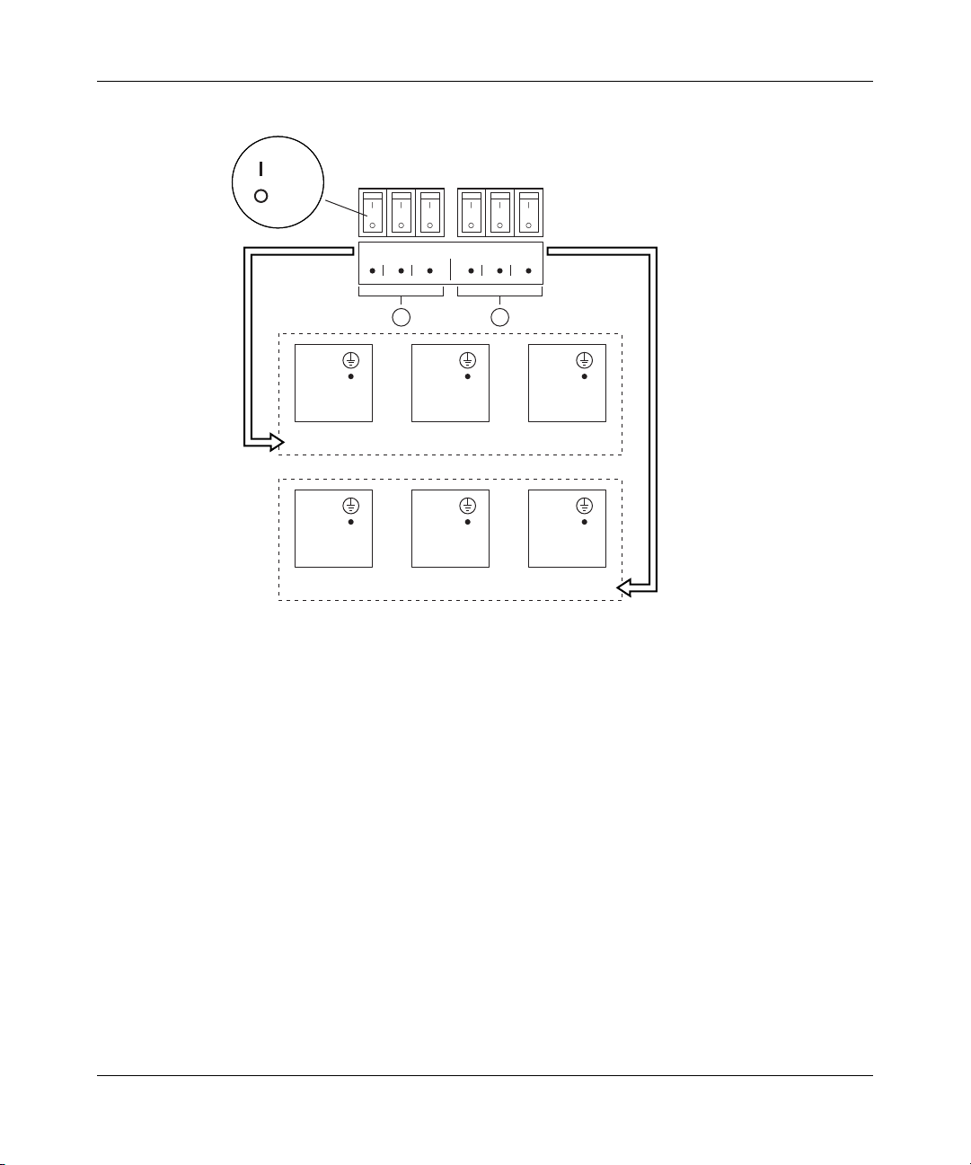
Figure 3 Shelf circuit breakers
= On
= Off
Chapter 1 Overview 21
Upper Shelf
123 123
PS 1
+ DC
– DC
Upper shelf power supplies
PS 1
+ DC
– DC
1 = Upper shelf LEDs
2 = Lower shelf LEDs
Lower Shelf
1
2
PS 2
+ DC
– DC
PS 2
+ DC
– DC
Lower shelf power supplies
Front of rack
PS 3
+ DC
– DC
PS 3
+ DC
– DC
10372EA
Installing the Breaker Interface Panel for the Ethernet Routing Switch 8010co Chassis
Page 22
22 Chapter 1 Overview
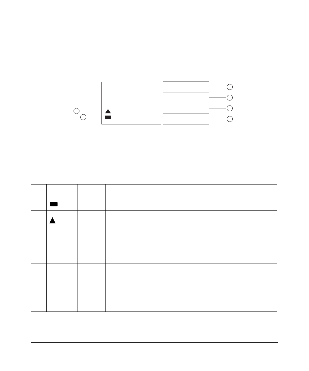
Alarm module display panel
The alarm module display panel (Figure 4), located on the BIP front panel,
provides visual status indications for one or two 8010co chassis in a single rack.
Figure 4 Alarm module display panel
3
4
5
6
10377EA
2
1
1 = Shelf alarm cable validation LED
2 = Shelf alarm cable fault LED
Alarm Module
POWER
CRITICAL
MAJOR
MINOR
3 = POWER indicator
4 = CRITICAL fault indicator
5 = MAJOR fault indicator
6 = MINOR fault indicator
See Tabl e 1 for a description of the LEDs.
Table 1 Alarm module display LEDs
Item Label/Icon Type Color/State Description
1 LED Green/On steady Shelf alarm cable validation LED—The alarm cables
are properly connected to the shelves.
2 LED Red/On steady Shelf alarm cable fault LED—The shelf alarm cables
3 POWER Indicator White/On steady Power indicator—The external DC power is available
4 CRITICAL Indicator Red/On steady Critical fault indicator—Indicates that a severe
are missing, not secured, or the shelf alarm jumpers
are not configured properly (see “Accessing the alarm
module” on page 30). This fault condition also lights
the MINOR fault indicator (see Minor fault description
in this table).
to the BIP.
service-affecting condition has occurred that requires
immediate corrective action. Common causes for this
type of fault condition include:
• Line card failure
• Temperature fault
• CPU fault when only one CPU is installed
312755-G Rev 00
Page 23

Chapter 1 Overview 23
Table 1 Alarm module display LEDs (continued)
Item Label/Icon Type Color/State Description
5 MAJOR Indicator Red/On steady Major fault indicator—Indicates that the system
hardware or software has identified a serious
disruption of service or that an important circuit failure
has occurred.
Common causes for this type of fault condition
include:
• CPU fault when two CPUs are installed
• Two fan trays are faulty
• Two power supplies are faulty
6 MINOR Indicator Yellow/On steady Minor fault indicator—Indicates a problem that does
not have a serious effect on customer service, or a
problem in circuits that are not essential to device
operation.
Common causes for this type of fault condition
include:
• Shelf alarm cables not installed or not connected
properly.
• Alarm module jumpers configured incorrectly.
• One power supply is faulty
• One fan tray is faulty
The alarm module can also be linked to other BIPs, and can provide visual and
audible alarms to aisle alarms and to the central office (see “Central office alarms”
on page 26).
Alarm support for the BIP is provided by the 8691SF or 8691omSF central
processing unit (CPU) in the 8010co chassis. The following conditions in the
8010co chassis generate alarms:
• Power supply failure
• Fan failure
• Overheating
• Line card error
•Master CPU failure
For details about the 8691SF or 8691omSF Central Processing Unit (CPU), see
the appropriate product chassis installation manual.
Installing the Breaker Interface Panel for the Ethernet Routing Switch 8010co Chassis
Page 24
24 Chapter 1 Overview
Front panel locking screws
The front panel locking screws allow you to open the front panel to access the
alarm module. The alarm module contains jumpers that you use to configure your
system alarm parameters.
For information about configuring your system alarm parameters, see “Accessing
the alarm module” on page 30.
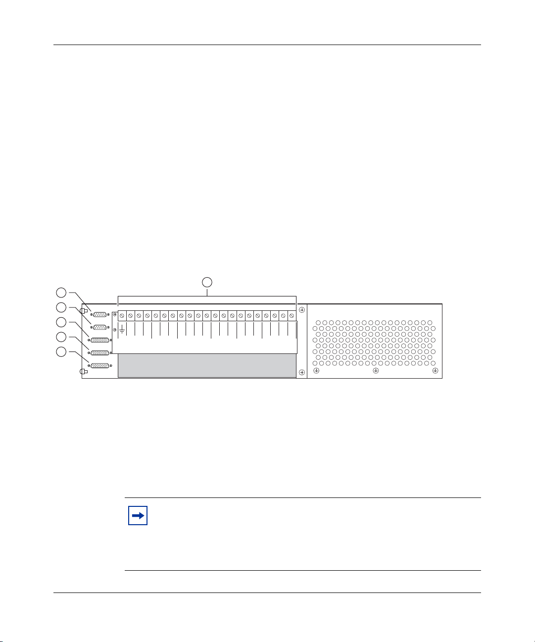
Back panel
Figure 5 shows the BIP back panel configuration (plastic back cover not shown).
Descriptions of the back panel components follow the figure.
Figure 5 Back panel components
1
2
3
4
5
32
1321 321321 A2A1B1B
PS (+)
PS (+)
Upper Shelf
A/B Input Feed
Returns
Lower Shelf
6
PS (-)
Lower Shelf
PS (-)
Upper Shelf
– 48 VDC
A/B Input Feeds
2
1 = J1 Upper shelf alarm connector
2 = J2 Lower shelf alarm connector
Shelf alarm connectors (upper and lower shelves)
The shelf alarm connectors allow you to configure the BIP to control more than
one 8010co chassis.
312755-G Rev 00
3 = J3 Central office alarm "in"
4 = J4 Central office alarm "out"
5 = J5 Standalone office alarm connector
6 = TB1 Power terminal block
10367EA
Note: The BIP ships from the factory with default alarm configurations
set for a single chassis in the lower shelf of the rack. If you install a
second chassis, you must also configure the jumper on the alarm module
to support that configuration. See “Accessing the alarm module” on
page 30 for information about jumper settings for your configuration.
Page 25
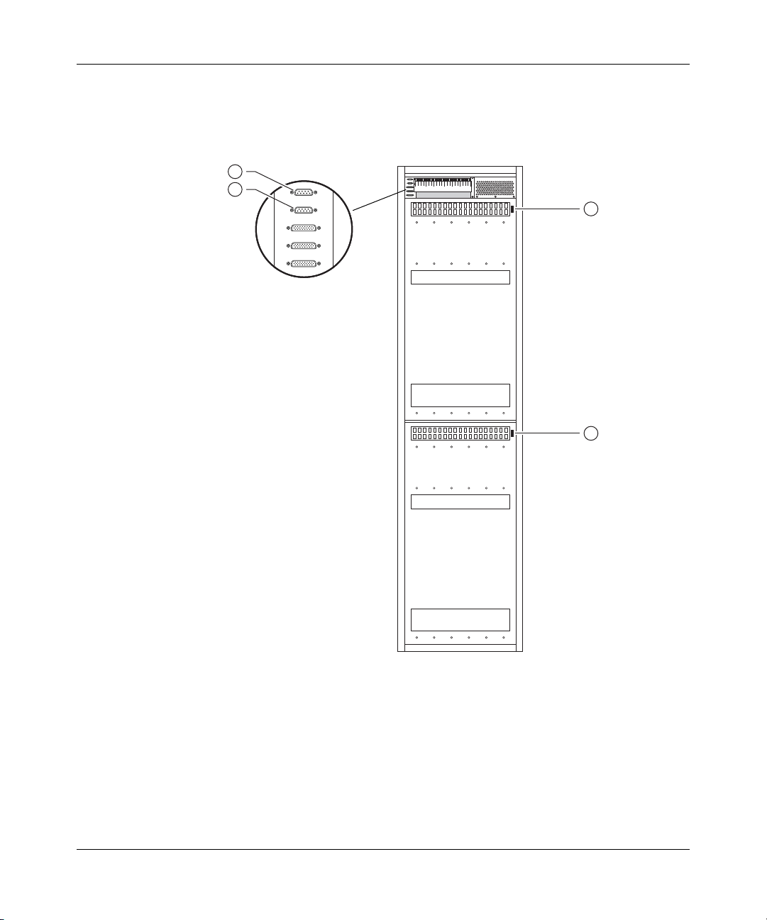
Chapter 1 Overview 25
Figure 6 shows the location of the shelf alarm connectors on the BIP and on two
8010co chassis (upper and lower shelves).
Figure 6 Shelf alarm connections (upper and lower shelves)
1
2
J1
J2
J3
J4
J5
3
4
1 = J1 (BIP upper shelf alarm connector)
2 = J2 (BIP lower shelf alarm connector)
3 = Upper shelf chassis alarm connector "out"
4 = Lower shelf chassis alarm connector "out"
10380EA
Installing the Breaker Interface Panel for the Ethernet Routing Switch 8010co Chassis
Page 26

26 Chapter 1 Overview
Central office alarms
The central office alarm connectors allow you to aggregate alarms from multiple
BIPs and route them to an aisle alarm and to the central office. Figure 7 shows
three BIPs configured to aggregate alarms from three racks. You can configure up
to ten BIPs in a series configuration to aggregate alarms.
Central office alarm cables are not provided as part of your BIP shipment. To
build your own central office alarm cables, see Appendix B, “BIP external cable
pin assignments,” on page 75.
Figure 7 Configuring multiple BIPs to aggregate office alarms
1
2
J1
J2
J3
J4
J5
32
1321 321321 A2A1B1B
PS (+)
Lower Shelf
PS (+)
Upper Shelf
A/B Input Feed
Returns
PS (-)
Lower Shelf
Upper Shelf
2
PS (-)
– 48 VDC
A/B Input Feeds
BIP 1
PS (-)
BIP 2
PS (-)
BIP 3
– 48 VDC
A/B Input Feeds
– 48 VDC
A/B Input Feeds
2
2
3
To central office
32
1321 321321 A2A1B1B
PS (+)
PS (+)
Lower Shelf
Upper Shelf
32
1321 321321 A2A1B1B
PS (+)
PS (+)
Lower Shelf
Upper Shelf
A/B Input Feed
Returns
A/B Input Feed
Returns
PS (-)
Lower Shelf
PS (-)
Lower Shelf
Upper Shelf
Upper Shelf
1 = J3 (central office alarm "in")
2 = J4 (central office alarm "out")
3 = Aisle alarm
10371EA
You can also configure one or more standalone BIPs to individually report alarm
status to the central office (Figure 8 on page 27).
312755-G Rev 00
Page 27

Chapter 1 Overview 27
This type of configuration allows you to independently monitor and control the
external audible and visual alarm status indications of the BIP at the central office.
Figure 8 Configuring standalone BIPs to report alarm status
J1
J2
J3
1
J4
J5
32
1321 321321 A2A1B1B
PS (+)
Lower Shelf
PS (+)
Upper Shelf
A/B Input Feed
Returns
PS (-)
Lower Shelf
PS (-)
Upper Shelf
– 48 VDC
A/B Input Feeds
2
To central office
BIP 1
32
1321 321321 A2A1B1B
PS (+)
Lower Shelf
PS (+)
Upper Shelf
A/B Input Feed
Returns
PS (-)
Lower Shelf
PS (-)
Upper Shelf
– 48 VDC
A/B Input Feeds
2
To central office
BIP 2
32
1321 321321 A2A1B1B
PS (+)
Lower Shelf
PS (+)
Upper Shelf
A/B Input Feed
Returns
PS (-)
Lower Shelf
PS (-)
Upper Shelf
– 48 VDC
A/B Input Feeds
2
To central office
BIP 3
1 = J5 (standalone office alarm connector)
10419EA
Power terminal block
The power terminal block is located on the back panel of the BIP. As shown in
Figure 9 on page 28, the power terminal block provides 21 connection blocks for
DC input and output feeds.
Installing the Breaker Interface Panel for the Ethernet Routing Switch 8010co Chassis
Page 28

28 Chapter 1 Overview
Figure 9 Power terminal block
1 10
2 3 5 64
7
8
9
32
1321 321321 A
PS (+)
Lower Shelf
1 = To frame (rack) ground
2 = To lower shelf power supplies (+DC terminals)
3 = To upper shelf power supplies (+DC terminals)
4 = Returns (A/B input feeds)
5 = To lower shelf power supplies (-DC terminals)
PS (+)
Upper Shelf
A/B Input Feed
Returns
PS (-)
Lower Shelf
6 = To upper shelf power supplies (-DC terminals)
7 = -48 VDC input feed (Primary A feed)
8 = -48 VDC input feed (Secondary A feed)
9 = -48 VDC input feed (Primary B feed)
10 = -48 VDC input feed (Secondary B feed)
PS (-)
Upper Shelf
2A1B1B2
– 48 VDC
A/B Input Feeds
10379EA
Figure 10 on page 29 shows an example of the BIP power terminal block cabling
including ground connections for two 8010co chassis and installed power
supplies.
As shown in this example, both upper and lower chassis are each fully configured
with three power supplies (one is redundant) and require four 60 A direct current
input feeds to the BIP (two feeds are redundant).
For more information, see “Connecting DC input power feeds to the BIP” on
page 52.
Caution: All DC input feeds to the breaker interface panel must be
equipped with an overcurrent protection device that limits current to a
maximum of 60 A. The overcurrent protection device can be any
approved, standard-delay, 60 A fuse or circuit breaker with an
interrupting current rating of not less than 10,000 A.
312755-G Rev 00
Page 29

Figure 10 Power and grounding example
PS 3
+ DC
– DC
PS 3
+ DC
–
DC
PS 3
+ DC
– DC
Return Secondary B
Return Primary B
Return Secondary A
Return Primary A
+DC PS1 Upper
+DC PS2 Upper
+DC PS3 Upper
+DC PS1 Lower
Equipment
rack
+DC PS2 Lower
+DC PS3 Lower
Chapter 1 Overview 29
-DC PS3 Lower
-DC PS2 Lower
-DC PS1 Lower
-DC PS3 Upper
-DC PS2 Upper
-DC PS1 Upper
-48 VDC Primary A
-48 VDC Secondary A
-48 VDC Primary B
-48 VDC Secondary B
Rack
grounding strip
example
Gnd BIP
Gnd PS 1 upper
Gnd PS 2 upper
Gnd PS 3 upper
Gnd upper shelf
Gnd PS 1 lower
Gnd PS 2 lower
Gnd PS 3 lower
Gnd lower shelf
Legend:
= Chassis ground
32
1321 321321 A
PS (+)
Lower Shelf
PS (+)
Upper Shelf
Power terminal block (BIP)
Upper shelf
PS 1
+ DC
– DC
Lower shelf
PS 1
+ DC
– DC
A/B Input Feed
Returns
PS 1
PS 2
PS 1
PS 2
PS (-)
Lower Shelf
+ DC
+ DC
– DC
– DC
+ DC
+ DC
– DC
– DC
PS (-)
Upper Shelf
PS 3
2A1B1B2
– 48 VDC
A/B Input Feeds
DC
Chassis
ground stud
Cable not
supplied
Chassis
ground stud
Cable not
supplied
= Earth ground
= Redundant equipment
10760EB
Installing the Breaker Interface Panel for the Ethernet Routing Switch 8010co Chassis
Page 30

30 Chapter 1 Overview
Accessing the alarm module
Danger: Ensure that the DC power source is off or disconnected at the
remote end before you perform any of the steps in this section. Be sure
that the DC input source power is locked out and tagged.
The alarm module contains jumpers that you can configure to allow the BIP to
monitor the shelf alarm cables for a single or dual chassis installation. The BIP
ships from the factory with default jumper configurations set for a single chassis
in the lower shelf of the rack. If you install a second chassis in the upper shelf, you
must configure the jumpers on the alarm module to support that configuration.
Note: The jumper configuration has no affect on the chassis status
alarms.
The BIP front panel opens to provide access to the jumpers on the alarm module.
To open the front panel:
312755-G Rev 00
1 Using a Phillips screwdriver, loosen the two front panel locking screws
(Figure 11).
Figure 11 Opening the front panel
1
R
E
W
O
P
L
A
IC
IT
R
C
R
O
J
A
M
R
O
IN
M
1 = Front panel locking screws (x 2)
10375FB
Page 31

Chapter 1 Overview 31
2 Gently lower the front panel to expose the alarm module (Figure 12).
Figure 12 Accessing the alarm module
1
1 = Alarm module
10365FB
Figure 13 shows a close-up view of the alarm module with jumpers J8 and J9
configured to monitor the shelf alarm cable for a single chassis in the lower shelf
only (default setting). Monitoring of the upper shelf alarm cable is disabled with
jumper J8, by default.
To enable the BIP to monitor the shelf alarm cable for a second chassis in the
upper shelf, you must place the upper shelf alarm jumper (J8) over pins 2 and 3.
Figure 13 Default jumper settings
2
3 2 1
J9
1
J9
3 2 1
J8
3
J8
1 = Alarm module
2 = J9 Lower shelf alarm jumper (enabled)
3 = J8 Upper shelf alarm jumper (disabled)
10366EB
Installing the Breaker Interface Panel for the Ethernet Routing Switch 8010co Chassis
Page 32

32 Chapter 1 Overview
Configuration example
Figure 14 shows a typical configuration using the optional breaker interface panel.
Figure 14 8010co chassis configuration with BIP option
1
2
312755-G Rev 00
3
1 = Breaker interface panel
2 = 8010co Chassis (upper shelf position)
3 = 8010co Chassis (lower shelf position)
10420EB
Page 33

Chapter 2
Installation
This chapter describes how to install the breaker interface panel and covers the
following topics:
• “Preparing to install the breaker interface panel” next
• “Installing the breaker interface panel” on page 36
• “Verifying the installation” on page 62
Preparing to install the breaker interface panel
Before begin the installation, verify that:
• Your shipment is complete and undamaged.
• You have the cables, tools, and other equipment that you need.
• Your installation site meets the physical, electrical, and environmental
requirements (see Appendix A, “Technical specifications,” on page 73).
33
The sections that follow help you prepare for installation.
Note: For a list of requirements that must be met for the 8010co chassis,
see the appropriate product chassis installation manual.
Installing the Breaker Interface Panel for the Ethernet Routing Switch 8010co Chassis
Page 34

34 Chapter 2 Installation
Shipment contents
Inspect all items for shipping damage. If you detect any damage, do not install the
BIP. Call the Nortel Technical Solutions Center in your area (see “How to get
Help” on page 16).
Your BIP shipment contains the following items (Figure 15):
Figure 15 Contents of the BIP shipping container
1
2
R
E
W
O
P
L
A
IC
IT
R
C
R
O
J
A
M
R
O
IN
M
312755-G Rev 00
3
4
5
6
1 = Breaker interface panel (BIP)
2 = BIP ground cable (x 1)
3 = 90-inch power supply ground cable (x 6)
4 = 125-inch power supply cable (x 6)
5 = 90-inch power supply cable (x 6)
6 = Shelf alarm cables (x 2)
10369FC
Page 35

Additional equipment
To install the BIP, you might need items that are not part of the BIP installation
kit. Before installing the BIP hardware, ensure that you obtain all the cables, tools,
and other equipment that you need. For information about office alarm cable pin
assignments, see Appendix B, “BIP external cable pin assignments,” on page 75.
Mounting hardware
You must install the BIP in an equipment rack. You need the following tools:
• Phillips screwdriver
• 7/16-inch hex wrench
You also need a rack that meets the following specifications:
• Heavy-duty steel construction
• Electronics Industries Association (EIA) standard hole-spacing
Chapter 2 Installation 35
You can install the BIP in the following 19-in. (48.26 cm) rack configurations:
• Standard 19-inch rack
• Hendry rack
You can install the BIP in a standard 23-inch rack using adapters provided by the
rack supplier. If your rack does not have threaded rail holes, you must use
cagenuts that are appropriate for the specific rack model you are using.
DC input electrical requirements
The installation site must meet the following electrical requirements for DC power
(Tabl e 2):
Table 2 DC power requirements
Nominal input voltage Maximum input current Physical
-48 VDC nominal 60 A Reinforced insulation
Installing the Breaker Interface Panel for the Ethernet Routing Switch 8010co Chassis
from the main DC power
Page 36

36 Chapter 2 Installation
Installing the breaker interface panel
Warning: Ensure that the DC power source is off or disconnected at the
remote end before you perform any of the steps in this section. You may
need to switch a circuit breaker off or turn off power at the DC input
source. Be sure that the DC input source power is locked out and tagged.
Note: The 8004DC power supply operates with the BIP. The BIP does
not support the 8005DC power supply.
This section covers the following topics:
• “Installing the hardware” next
• “Connecting cables to the chassis power supplies” on page 38
• “Routing power supply cables to the BIP” on page 47
• “Connecting the ground cables to the rack grounding strip” on page 48
• “Connecting the power supply cables to the BIP” on page 49
• “Connecting DC input power feeds to the BIP” on page 52
• “Replacing covers” on page 59
• “Installing shelf alarm cables” on page 61
Installing the hardware
312755-G Rev 00
Before beginning the BIP hardware installation, ensure that you:
• Always install the BIP in the uppermost position in the rack to allow for
maximum convection cooling requirements.
• Ground the rack to the same grounding electrode used by the power service in
the area.
The ground path must be permanent and must not exceed 1 ohm of resistance
from the rack to the grounding electrode.
Page 37

Chapter 2 Installation 37
To install the BIP:
1 Remove the plastic back cover from the BIP terminal block (Figure 16).
Figure 16 Removing the plastic back cover from the BIP
2
1
32
1321 321321 A2A1B1B
PS (+)
PS (+)
Upper Shelf
A/B Input Feed
Returns
Lower Shelf
Lower Shelf
PS (-)
PS (-)
Upper Shelf
2
– 48 VDC
A/B Input Feeds
2
1 = Back cover (plastic)
2 = Cover screws (x 4)
Caution: The BIP weighs 33.9 lbs (15.4 kg). The next step requires two
persons to mount the BIP in the rack.
2 Position the BIP in the uppermost position in the rack and align the holes in
the mounting bracket with the holes in the rack.
3 Insert 2 screws, appropriate for your rack type, into each mounting bracket
and tighten them (Figure 17).
Figure 17 Installing the BIP in the rack
R
E
W
O
P
L
A
IC
IT
R
C
R
O
J
A
M
R
O
IN
M
10378FB
4 After the BIP is secured in the rack, go to the next section, “Connecting cables
to the chassis power supplies” on page 38.
Installing the Breaker Interface Panel for the Ethernet Routing Switch 8010co Chassis
Page 38

38 Chapter 2 Installation
Connecting cables to the chassis power supplies
This section describes how to connect the BIP power cables to the 8010co chassis
8004DC power supplies. These procedures assume that all required power
supplies were previously installed during the 8010co chassis installation.
Note: This guide does not describe how to remove or replace power
supplies in the 8010co chassis. For detailed instructions about adding
power supplies or modifying an existing configuration, see the
appropriate product chassis installation manual.
Before beginning the procedures in this section, note the following:
• A 8010co chassis configuration can consist of one or two chassis in a single
rack. If a single chassis is installed, it is always installed in the lower shelf
position.
Note: For a single chassis installation, always install the chassis in the
lower shelf position to stabilize the rack.
312755-G Rev 00
• Each chassis can be configured with up to three power supplies. The cabling
for each power supply comprises three conductors: the positive lead wire, the
negative lead wire, and the ground lead.
• To access the power supplies, you may have to remove the bottom front bezel
from both the upper shelf and lower shelf 8010co chassis.
Warning: Ensure that the DC power source is off or disconnected at the
remote end before you perform any of the steps in this section. You may
need to switch a circuit breaker off or turn off power at the DC input
source. Be sure that the DC input source power is locked out and tagged.
Note: The 321325-A bezel does not need to be removed to access the
power supplies.
Page 39

Chapter 2 Installation 39
To connect cables to the chassis power supplies:
1 Remove the 8010co chassis bottom bezels (if required).
a Using a Phillips screwdriver, loosen the 2 captive screws securing the
bezel to the chassis (Figure 18).
b Pull the top of the bezel forward and then lift the 312096-A bezel from the
two tabs on the bottom of the chassis.
c Repeat steps a and b for the second chassis, if installed.
Figure 18 Removing the 8010co chassis bottom 312096-A bezel
il
a
F
s
s
a
l
i
a
F
s
s
a
P
P
Bottom bezel
10422FA
Installing the Breaker Interface Panel for the Ethernet Routing Switch 8010co Chassis
Page 40

40 Chapter 2 Installation
2 Locate the power supplies (Figure 19).
With the bezel removed, you can see the power supplies. The chassis can
contain up to three power supplies. (Power supplies reside in bay 1, bay 2, and
bay 3, viewed left to right from the front of the chassis.)
Figure 19 Location of power supplies
Fail
Pass
Fail
Pass
312755-G Rev 00
1 = Power supply (bay 1)
2 = Power supply (bay 2)
3 = Power supply (bay 3)
C
D
+
C
C
D
+
C
C
D
+
C
-D
-D
-D
3
2
1
10423FA
Page 41

Chapter 2 Installation 41
3 Loosen the 2 retaining screws on the power supply located in bay 1 in the
lower chassis (Figure 20).
Figure 20 Loosening the power supply retaining screws
+DC
+DC
+DC
-DC
-DC
-DC
10424FA
4 Lift the extractor lever to disconnect the power supply from the backplane
connector, and then pull the power supply partially out of the chassis
(Figure 21).
Figure 21 Disconnecting the power supply from the chassis backplane
+DC
+DC
-DC
C
+D
C
-D
-DC
10425FA
Installing the Breaker Interface Panel for the Ethernet Routing Switch 8010co Chassis
Page 42

42 Chapter 2 Installation
5 Remove the Phillips screw securing the plastic safety cover to the power
supply, and then remove the cover (Figure 22).
Save the Phillips screw and the cover for replacement later.
Figure 22 Removing the plastic safety cover from the power supply
+DC
-DC
10426FA
312755-G Rev 00
6 Note the position of the ground stud and of the positive and negative power
supply inputs (Figure 23).
Figure 23 Power supply input and ground stud location
1
+DC
-DC
1 = Ground stud
2 = Positive power inputs
3 = Negative power inputs
2
3
10427FA
Page 43

Chapter 2 Installation 43
7 Locate the following items in the shipping container (Figure 24).
• 125-inch power cables—for power supplies located in the lower chassis
• 90-inch power cables—for power supplies located in the upper chassis
• 90-inch ground cables—for grounding of power supplies located in the
upper and lower chassis
Figure 24 Power supply cables
1
2
3
1 = 125-inch power supply cables (x 6)
2 = 90-inch power supply cables (x 6)
3 = 90-inch power supply ground cables (x 6)
10428FC
8 Attach one end of a 90-inch ground cable to the grounding stud on the power
supply. Use a 7/16-inch hex wrench to fasten the hardware in the correct order
(Figure 25).
The hardware (washers and nuts) are included with the power supply
shipment.
Figure 25 Attaching the ground lead
1
2
3
4
5
1 = Grounding stud
2 = Flat washer
3 = Crimp lug
4 = Lock washer
5 = Hex nut
6 = Earth ground lead
Installing the Breaker Interface Panel for the Ethernet Routing Switch 8010co Chassis
+DC
-DC
6
10297FA
Page 44

44 Chapter 2 Installation
9 Attach the lug end of a 125-inch power supply cable to the positive terminal
on the power supply (Figure 26).
Use a 7/16-inch hex wrench to fasten the hardware in the correct order.
Figure 26 Attaching the positive lead
1
2
3
+DC
-DC
312755-G Rev 00
1 = Two-hole crimp lug
2 = Lock washer (x 2)
3 = Hex nut (x 2)
4 = Positive lead wire
4
10429FA
Page 45

Chapter 2 Installation 45
10 Attach the lug end of a 125-inch power supply cable to the negative terminal
on the power supply (Figure 27).
Use a 7/16-inch hex wrench to fasten the hardware in the correct order.
Figure 27 Attaching the negative lead
1
+DC
-DC
2
3
1 = Two-hole crimp lug
2 = Lock washer (x 2)
3 = Hex nut (x 2)
4 = Negative lead wire
4
10430FA
11 Replace the plastic safety cover on the power supply (Figure 28).
Figure 28 Replacing the plastic safety cover on the power supply
+DC
-DC
10431FA
Installing the Breaker Interface Panel for the Ethernet Routing Switch 8010co Chassis
Page 46

46 Chapter 2 Installation
12 Secure the power supply in bay 1 of the lower chassis (Figure 29).
a Use the power supply handle to push the power supply firmly into bay 1.
b Push the extractor lever down to lock the power supply in place.
c Tighten the two power supply retaining screws.
Figure 29 Replacing the power supply
+DC
+DC
-DC
C
+D
C
-D
-DC
312755-G Rev 00
10432FB
13 Perform steps 3 through 12 for each power supply in the system configuration,
including the upper shelf chassis, if installed.
Use the shorter, 90-inch power cables for upper shelf power supplies.
14 After all power supplies are cabled, go to the next section,“Routing power
supply cables to the BIP” on page 47.
Page 47

Routing power supply cables to the BIP
After you connect all cables to the chassis power supplies, you must route the
power supply cable leads from each chassis to the BIP. If you installed an upper
and lower shelf chassis, and each chassis has three power supplies, you have 18
separate cables to route to the BIP. For this reason, Nortel recommends that you
label the cables and loosely bundle and fasten them with tie-wraps along the path.
To route the cables to the BIP:
1 Label the unconnected ends of the cable leads for each power supply
according to their destination on the BIP (Figure 30).
Figure 30 shows an example of one set of power supply cables for a power
supply that is located in bay 1 of the upper shelf chassis. The cables were
preassembled with the appropriate crimp lugs.
Be sure to label the cable leads appropriately for the power supplies in both
the upper and lower shelves.
Figure 30 Labeling cables for the BIP
Chapter 2 Installation 47
1
2
1 = BIP ground cable (x 1)
2 = Power supply ground cable (x 6)
Rack Ground
Gnd PS 1 Upper
2 Use tie-wraps or cable ties to loosely bundle the cable leads for each power
supply into a single manageable cable.
3 Route the bundled cables under each chassis to the back of the rack.
4 Separate the green (with yellow stripe) ground cable leads from the bundled
cables, and route them to the base of the rack.
Installing the Breaker Interface Panel for the Ethernet Routing Switch 8010co Chassis
Bip Ground
Rack Ground
3
4
5
3 = Power supply negative lead cable (x 6)
4 = Power supply positive lead cable (x 6)
5 = Label tags (optional, use as required)
-DC PS 1 Upper
+DC PS 1 Upper
-DC PS 1 Upper
+DC PS 1 Upper
10411EB
Page 48

48 Chapter 2 Installation
5 Route the remaining (black) power supply cables from the back of the lower
and upper shelf chassis to the back panel of the BIP, loosely fastening them
with tie-wraps along the path.
6 Loosely support the power supply cables with tie-wraps above the BIP power
terminal block.
7 Proceed to, “Connecting the ground cables to the rack grounding strip.”
Connecting the ground cables to the rack grounding strip
To connect the power supply ground cables to the rack grounding strip:
1 Locate the rack grounding strip at the back base of the rack (Figure 31).
Note: Figure 31 shows an example of a rack grounding strip. Your rack
grounding strip can look different than the one shown in this example.
2 Attach the lug ends of the power supply ground cables to the rack grounding
strip (Figure 31).
312755-G Rev 00
Use a 7/16-inch hex wrench to fasten the hardware in the correct order.
Figure 31 Rack grounding strip example
1
2
3
4
1 = Hex head bolt
2 = Lock washer
3 = Ground crimp lug
4 = Rack grounding strip
10433FA
3 Proceed to “Connecting the power supply cables to the BIP” on page 49.
Page 49

Connecting the power supply cables to the BIP
To connect the power supply cables to the BIP:
1 Locate one of the power supply cables.
2 Match the labeled tag on the power supply cable with the correct location on
the power terminal block (Figure 32).
The power terminal block label indicates a location for the positive and
negative power supply leads for both the upper shelf and lower shelf power
supplies.
3 Loosen the appropriate power terminal block screw, and then insert the cable
lead (item 1 in Figure 32). Tighten the screw securely.
Item 2 in Figure 32 shows the negative cable lead from power supply 1 in the
upper shelf correctly connected to the power terminal block.
Figure 32 Attaching power supply cable leads to the BIP
Chapter 2 Installation 49
1
+DC PS1 Upper
32
1321 321321 A2A1B1B
PS (+)
PS (+)
Upper Shelf
A/B Input Feed
Lower Shelf
3
1 = Positive lead wire from power
supply 1, upper shelf
2 = Negative lead wire from power
supply 1, upper shelf
Installing the Breaker Interface Panel for the Ethernet Routing Switch 8010co Chassis
2
-DC PS1 Upper
PS (-)
PS (-)
Returns
Lower Shelf
Upper Shelf
– 48 VDC
A/B Input Feeds
3 = Power terminal block label
2
10393FA
Page 50

50 Chapter 2 Installation
4 Repeat steps 1 through 3 for each remaining power supply in your
configuration (Figure 33).
Figure 33 Upper and lower shelf power cables connected to the BIP
1
2
32
1321 321321 A2A1B1B
PS (+)
Lower Shelf
PS (+)
Upper Shelf
1 = Positive lead wires
(lower shelf power supplies)
2 = Positive lead wires
(upper shelf power supplies)
5 Locate the BIP ground cable (see Figure 30 on page 47).
3
4
PS (-)
A/B Input Feed
Returns
Lower Shelf
PS (-)
Upper Shelf
A/B Input Feeds
3 = Negative lead wires
(lower shelf power supplies)
4 = Negative lead wires
(upper shelf power supplies)
2
– 48 VDC
10394FA
312755-G Rev 00
Page 51

6 Attach one end of the BIP ground cable to the power terminal block
(Figure 34).
a Loosen the power terminal block screw just enough to insert the ground
cable lead (item 1 in Figure 34).
b Insert the lead and tighten the screw securely.
Figure 34 Attaching the BIP ground cable
Chapter 2 Installation 51
1
+DC PS1 Upper
32
1321 321321 A2A1B1B
PS (+)
Lower Shelf
PS (+)
Upper Shelf
3
1 = Positive lead wire from power
supply 1, upper shelf
7 Route the other end of the BIP ground cable to the rack grounding strip near
the base of the rack (see Figure 31 on page 48).
Use a 7/16-inch hex wrench to fasten the hardware in the correct order.
8 Go to the next section, “Connecting DC input power feeds to the BIP” on
page 52.
2
PS (-)
A/B Input Feed
Returns
Lower Shelf
PS (-)
Upper Shelf
3 = Power terminal block label
-DC PS1 Upper
– 48 VDC
A/B Input Feeds
2
Installing the Breaker Interface Panel for the Ethernet Routing Switch 8010co Chassis
Page 52

52 Chapter 2 Installation
Connecting DC input power feeds to the BIP
Danger: Due to high-energy hazards, only qualified service personnel
are permitted to connect the BIP to the DC power source.
Warning: Ensure that the DC power source is off or disconnected on the
remote end before you perform any of the steps in this section. You may
need to switch a circuit breaker off or turn off power at the DC input
source.
Nortel does not supply the cables for connecting the breaker interface panel to the
DC input power source. You must select cables that comply with the electrical
code of the country where you intend to use the DC-DC power supply.
Caution: As the installer, you have the sole responsibility for ensuring
that the connection cable used with the breaker interface panel is
appropriate for use with the DC power source to which the power supply
is connected. Consider gauge, flammability, and mechanical
serviceability when determining which cables to use.
312755-G Rev 00
You can connect up to two “A” feeds and two “B” feeds to your 8010co chassis
configuration for redundancy. Each chassis can require up to 60 A service for
maximum operating power.
As shown in Figure 35 on page 53, the primary B feed (B
1
for the primary A feed (A
for the secondary A feed (A
), and the secondary B feed (B2) provides redundancy
2
).
1
) provides redundancy
Note: An optional third power supply in the chassis provides redundancy
and high-availability operation. In the same way, the BIP provides
redundancy and high-availability operation by allowing two additional
“B” feeds to provide redundancy for single or dual chassis installations.
Page 53

Figure 35 A and B feed example
Chapter 2 Installation 53
BIP
Upper shelf chassis
60 A
60 A
60 A
60 A
A
2
B
1
A
1
B
= A feeds
30 A
30 A
30 A
30 A
30 A
30 A
30 A
PS1
30 A
PS2 PS3
Lower shelf chassis
30 A
PS1
30 A
PS2 PS3
= Redundant power supply
2
= B feeds
= Redundant feed
10400EC
Tabl e 3 lists input power options for single and dual chassis installations.
Table 3 Single chassis and dual chassis input options
Single chassis input
Non-redundant input power A
Redundant input power A1 and B
* For a single chassis installation, always install the chassis in the lower shelf position to stabilize
the rack.
1
1
*
Dual chassis input
A1 and A
2
A1 and B1, A2 and B
2
Installing the Breaker Interface Panel for the Ethernet Routing Switch 8010co Chassis
Page 54

54 Chapter 2 Installation
To connect the DC input feeds to the BIP:
1 Locate the DC power source for the DC input feed.
Warning: Ensure that the DC power source is off or disconnected on the
remote end before you perform any of the steps in this section. You may
need to switch a circuit breaker off or turn off power at the DC input
source.
2 Determine the power requirements for your configuration (see Figure 35 on
page 53).
3 Locate the A and B -48 VDC input feeds (Figure 36).
Note: Figure 36 shows an example of a site DC input conduit. Your DC
input conduit can look different or can be in a different location than the
one shown in the following examples.
The -48 VDC input feed cables should be tagged with source labels (for
example, -48 VDC Input feed or -48 VDC Return). If they are not labeled, and
you are not sure of the source, ask for assistance from a qualified electrician.
312755-G Rev 00
Figure 36 Locating the A and B -48 VDC input feeds
-48 VDC Feeds
-48VDC A feed 1
Return A feed 1
-48VDC A feed 2
Return A feed 2
-48VDC B feed 1
Return B feed 1
-48VDC B feed 2
Return B feed 2
10401EA
Page 55

Chapter 2 Installation 55
4 Connect the -48 VDC input feeds according to your configuration
requirements.
a Match the tagged -48 VDC input feed cable lead with the correct power
terminal block on the back of the BIP (Figure 37).
a Loosen the power terminal block screw just enough to insert the cable
lead (item 1 in Figure 37).
b Insert the lead and tighten the screw securely.
Figure 37 Connecting the A and B -48 VDC input feeds to the BIP (1 of 2)
-48 VDC Feeds
1
32
1321 321321 A2A1B1B
PS (+)
PS (+)
Upper Shelf
A/B Input Feed
Returns
Lower Shelf
1 = -48 VDC input feed (Primary A feed)
Installing the Breaker Interface Panel for the Ethernet Routing Switch 8010co Chassis
PS (-)
Lower Shelf
PS (-)
Upper Shelf
-48 VDC A feed 1
– 48 VDC
A/B Input Feeds
2
10406FA
Page 56

56 Chapter 2 Installation
5 Connect the remaining -48 VDC input feeds and returns as required
(Figure 38).
Note: Figure 38 shows the attachment of two “A” feeds and two “B”
feeds to the BIP. Note that there is a primary and a secondary A feed, as
well as a primary and secondary B feed (see Figure 35 on page 53 for
configuration details).
Figure 38 Connecting the A and B -48 VDC input feeds to the BIP (2 of 2)
-48 VDC Feeds
1
– 48 VDC
A/B Input Feeds
2
32
1321 321321 A2A1B1B
PS (+)
Lower Shelf
PS (+)
Upper Shelf
A/B Input Feed
Returns
PS (-)
Lower Shelf
PS (-)
Upper Shelf
1 = -48 VDC input feeds (Primary A, Secondary A, Primary B, Secondary B)
312755-G Rev 00
10407FA
Page 57

6 Connect the A/B input feed returns.
Note: The total number (quantity) of Input feed return cable leads must
match the total number of Input feeds used for your installation.
a Locate the A/B Input Feed Returns section of the power terminal block.
b Loosen one of the four available A/B input feed return connection screws
just enough to insert the cable lead (item 1 in Figure 39).
You can use any of the four available input feed return connections.
c Insert the lead and tighten the screw securely.
Figure 39 Connecting the A/B input feed returns (1 of 2)
-48 VDC Feeds
Chapter 2 Installation 57
1
Return A feed 1
2
– 48 VDC
A/B Input Feeds
2
32
1321 321321 A2A1B1B
PS (+)
Lower Shelf
PS (+)
Upper Shelf
A/B Input Feed
Returns
PS (-)
Lower Shelf
PS (-)
Upper Shelf
1 = -48 VDC input feed Return (Primary A feed Return)
2 = -48 VDC input feeds (Primary A, Secondary A, Primary B, Secondary B)
Installing the Breaker Interface Panel for the Ethernet Routing Switch 8010co Chassis
10408FA
Page 58

58 Chapter 2 Installation
7 Connect the remaining -48 VDC input returns as required (Figure 40).
Figure 40 shows the BIP with all power cables and returns installed.
Note: Be sure to properly support the cables with cable ties to avoid
undue stress to the power terminal block.
Figure 40 Connecting the A/B input feed returns (2 of 2)
-48 VDC Feeds
32
PS (+)
Lower Shelf
312755-G Rev 00
– 48 VDC
A/B Input Feeds
2
1321 321321 A2A1B1B
PS (+)
Upper Shelf
A/B Input Feed
Returns
PS (-)
Lower Shelf
PS (-)
Upper Shelf
8 Go to the next section, “Replacing covers” on page 59.
10409FA
Page 59

Replacing covers
After you complete all of the cabling requirements as described in the previous
sections, you must replace the plastic back cover on the BIP and the 8010co
chassis bezel(s) that were removed earlier in these procedures.
Before you replace the covers and bezels, be sure that all cables are routed
properly from under the chassis bays, through the rack, and up to the BIP power
terminal block. Check that all tie-wraps are secured, and give special attention to
the cables at the power terminal strip; the cable leads must be supported to avoid
undue stress on the terminal block.
1 Replace the plastic back cover on the BIP (Figure 41).
Figure 41 Replacing the plastic back cover on the BIP
Chapter 2 Installation 59
– 48 VDC
A/B Input Feeds
2
32
1321 321321 A2A1B1B
PS (+)
Lower Shelf
PS (+)
Upper Shelf
1
A/B Input Feed
Returns
PS (-)
Lower Shelf
Upper Shelf
2
PS (-)
1 = Back cover (plastic)
2 = Cover screws (x 4)
Installing the Breaker Interface Panel for the Ethernet Routing Switch 8010co Chassis
10410FA
Page 60

60 Chapter 2 Installation
2 Replace the 8010co chassis bezel.
a Set the notch (on both ends of the 312096-A bezel) into the tabs on the
chassis (Figure 42).
b Lift the top of the bezel up, and then align the captive screws with the
holes in the chassis.
c Using a Phillips screwdriver, tighten the 2 captive screws to secure the
bezel to the chassis.
d Replace the bezel on the second chassis, if installed.
Figure 42 Replacing the 8010co chassis 312096-A bezel
Fail
Fail
Pass
Pass
312755-G Rev 00
Bottom bezel
10434FA
3 Go to the next section, “Installing shelf alarm cables” on page 61.
Page 61

Installing shelf alarm cables
Note: The BIP ships from the factory with default alarm configurations
set for a single chassis in the lower shelf of the rack. If you install a
second chassis, you must configure the jumpers on the alarm module to
support that configuration. See “Accessing the alarm module” on page 30
if you need to modify the shelf alarm jumpers.
1 To install the shelf alarm cable for a single chassis in the lower shelf:
a Locate the shelf alarm cables in the shipping container.
b Connect one end of the shelf alarm cable to the J2 connector on the back
of the BIP (Figure 43).
c Connect the other end of the shelf alarm cable to the lower shelf chassis
alarm connector, on the lower shelf chassis.
Figure 43 Installing shelf alarm cables
1
2
J1
J2
J3
J4
J5
Chapter 2 Installation 61
3
4
1 = J1 (BIP upper shelf alarm connector)
2 = J2 (BIP lower shelf alarm connector)
3 = Upper shelf chassis alarm connector "out"
4 = Lower shelf chassis alarm connector "out"
10380EA
Installing the Breaker Interface Panel for the Ethernet Routing Switch 8010co Chassis
Page 62

62 Chapter 2 Installation
2 To install the shelf alarm cable for a second chassis in the upper shelf:
a Configure the jumpers on the alarm module to support a second chassis in
the upper shelf as described in “Accessing the alarm module” on page 30.
b Connect one end of the shelf alarm cable to the J1 connector on the back
of the BIP (Figure 43).
c Connect the other end of the shelf alarm cable to the upper shelf chassis
alarm connector, on the upper shelf chassis.
After successfully installing the shelf alarm cables, go to the next section
“Verifying the installation.”
Verifying the installation
This section describes how to verify the BIP hardware installation. It includes the
following topics:
• “Initial power-up,” next
• “Verifying the LEDs” on page 63
• “Powering off the system” on page 64
312755-G Rev 00
Before powering up the system to verify the installation, be sure that:
• All cables are installed and properly secured.
• All safety covers, filler panels, and bezels are installed and secure.
• All tools and installation materials are removed.
• You notify others working in the area that the system power is about to be
turned on.
Page 63

Initial power-up
Danger: Due to high-energy hazards, only qualified service personnel
are permitted to connect the BIP to the DC power source.
To power up the 8010co chassis:
1 Set the six circuit breakers on the BIP front panel to the off position (O = Off).
2 Set the switches for all power supplies in the upper and lower chassis to the
off position (O = Off).
You can access the power supply switches with the bezels installed.
3 Turn on the input feed power at the DC power source.
Verifying the LEDs
1 Verify the following LEDs on the BIP:
— The (white) POWER Indicator on the BIP front panel is on.
— The (green) shelf alarm cable validation LED is on steady.
Chapter 2 Installation 63
The green shelf alarm cable validation LED indicates that the shelf alarm
cables are installed properly.
(If there is a problem with the shelf alarm cable installation or jumper
settings, the red shelf alarm cable fault LED turns on.)
2 Set the six circuit breakers on the BIP front panel to the on position (| = On).
3 Set the switches for all power supplies in the upper and lower chassis to the on
position (| = On).
Note: When you first install a 8010co chassis that contains two or three
power supplies, you must turn on two of the power supply units
simultaneously. If you wait longer to turn on the second power supply,
one of the power supplies can shut down. To correct this condition, turn
off both power supplies, wait at least 30 seconds, and then turn on both
power supplies again simultaneously.
Installing the Breaker Interface Panel for the Ethernet Routing Switch 8010co Chassis
Page 64

64 Chapter 2 Installation
4 Verify the following LEDs on the 8010co chassis:
— The (green) power supply LEDs for each power supply in both the upper
and lower chassis are on.
(If any of the power supply LEDs are not on, replace the power supply.)
— The chassis fans are powering up.
If any of the previous steps indicate a problem with the installation, do the
following:
1 Set the switches for all power supplies in the upper and lower chassis to the
off position (O = Off).
2 Set the six circuit breakers on the BIP front panel to the off position (O = Off).
3 Check that all cables are installed properly, and that all power supplies are
firmly seated in their bays.
4 Set the six circuit breakers on the BIP front panel to the on position (| = On).
5 Set the switches for all power supplies in the upper and lower chassis to the on
position (| = On).
Powering off the system
312755-G Rev 00
6 Proceed to “Verifying the LEDs” on page 63.
If the problem persists, go to Chapter 3, “Problem solving,” on page 67.
To power off the system:
1 Set the switches for all power supplies in the upper and lower chassis to the
off position (O = Off).
You can access the power supply switches with the bezels installed.
2 Set the six circuit breakers on the BIP front panel to the off position (O = Off).
3 Turn off the input feed power at the DC power source.
Warning: Ensure the DC power source is off or disconnected. You may
need to switch a circuit breaker off or turn off power at the DC input
source. Be sure that the DC input source power is locked out and tagged.
Page 65

Chapter 2 Installation 65
Note: When you power off the 8010co chassis, wait at least 30 seconds
before turning the power supplies back on.
4 Continue with the installation of the 8010co chassis as described in the
appropriate product chassis installation manual.
Installing the Breaker Interface Panel for the Ethernet Routing Switch 8010co Chassis
Page 66

66 Chapter 2 Installation
312755-G Rev 00
Page 67

Chapter 3
Problem solving
This chapter describes how to isolate and diagnose problems with your breaker
interface panel and associated 8010co chassis.
This chapter covers the following topics:
• “Interpreting the LEDs” (next)
• “Diagnosing and correcting the problem” on page 70
• “Corrective actions” on page 71
The topics lead you through a logical process for troubleshooting the BIP and the
associated 8010co chassis components. The BIP LEDs provide visual indications
of problems that can occur with the 8010co chassis and installed components, as
well as system status during normal operations.
To become familiar with the various states that the LEDs can exhibit during
normal operation, go to the next section, “Interpreting the LEDs” on page 68.
67
For help in determining a problem, go to “Diagnosing and correcting the problem”
on page 70. That section describes symptoms and corrective actions you can
perform to resolve specific problems.
If the corrective actions determine that a chassis component needs replacing, see
the appropriate product chassis installation manual for replacement and removal
procedures.
If you still have problems with your system after completing the instructions in
this chapter, contact the Nortel Technical Solutions Center.
Installing the Breaker Interface Panel for the Ethernet Routing Switch 8010co Chassis
Page 68

68 Chapter 3 Problem solving
Interpreting the LEDs
All BIP LEDs and indicators are located on the front panel (Figure 44).
Figure 44 BIP LEDs and indicators
Upper Shelf
123 123
Lower Shelf
Alarm Module
4 5
POWER
CRITICAL
MAJOR
MINOR
1
1 = Shelf circuit breakers LEDs
2 = Shelf alarm cable fault LED
3 = Shelf alarm cable validation LED
4 = POWER indicator
5 = CRITICAL fault indicator
2
3
6 = MAJOR fault indicator
7 = MINOR fault indicator
7 6
10435EB
Tabl e 4 describes the BIP LEDs and indicators.
Table 4 BIP LEDs and indicators
Item Label/Icon Type Color/State Description
1 Upper Shelf/
Lower Shelf
2 LED Red/On steady Shelf alarm cable fault LED—The shelf alarm
3 LED Green/On steady Shelf alarm cable validation LED —The shelf alarm
LED Red/On steady Circuit breaker LEDs (for upper shelf and lower
shelf power supplies)—Indicates that a circuit
breaker has tripped due to an overcurrent condition
with the associated power supply.
This fault condition also lights the (red) MAJOR fault
indicator (see MAJOR fault description in this table).
No alarm is generated when a shelf circuit breaker
is manually switched on (|) or off (O).
cables are missing, not secured, or the shelf alarm
jumpers are not configured properly (see
“Accessing the alarm module” on page 30). This
fault condition also lights the MINOR fault indicator
(see Minor fault description in this table).
cables are properly connected to the shelves.
312755-G Rev 00
Page 69

Chapter 3 Problem solving 69
Table 4 BIP LEDs and indicators (continued)
Item Label/Icon Type Color/State Description
4 POWER Indicator White/On steady Power indicator—The external DC power is
available to the BIP.
5 CRITICAL Indicator Red/On steady Critical fault indicator—Indicates that a severe
6 MAJOR Indicator Red/On steady Major fault indicator—Indicates that the system
7 MINOR Indicator Yellow/On steady Minor fault indicator —Indicates a problem that
service-affecting condition has occurred that
requires immediate corrective action. Common
causes for this type of fault condition include:
• Line card failure
• Temperature fault
• CPU fault when only one CPU is installed
hardware or software has identified a serious
disruption of service or that an important circuit
failure has occurred.
Common causes for this type of fault condition
include:
• CPU fault when two CPUs are installed
• Two fan trays are faulty
• A power supply circuit breaker has tripped due
to an overcurrent condition
• Two power supplies are faulty
does not have a serious effect on customer service,
or a problem in circuits that are not essential to
device operation.
Common causes for this type of fault condition
include:
• Shelf alarm cables not installed or not
connected properly.
• Alarm module jumpers configured incorrectly.
• One power supply is faulty
• One fan tray is faulty
If you need more help, go to the next section, “Diagnosing and correcting the
problem” on page 70.
Installing the Breaker Interface Panel for the Ethernet Routing Switch 8010co Chassis
Page 70

70 Chapter 3 Problem solving
Diagnosing and correcting the problem
Before you perform the problem-solving steps in this section, complete the
following steps:
1 Set the switches for all power supplies in the upper and lower chassis to the
off position (O = Off).
2 Set the six circuit breakers on the BIP front panel to the off position (O = Off).
3 Check that all cables are installed properly, and that all power supplies are
firmly seated in their bays.
4 Set the six circuit breakers on the BIP front panel to the on position (| = On).
5 Set the switches for all power supplies in the upper and lower chassis to the on
position (| = On).
6 Verify the following LEDs on the BIP:
— The (white) POWER Indicator on the BIP front-panel is on.
— The (green) shelf alarm cable validation LED is on steady.
7 Verify the following LEDs on the 8010co chassis:
312755-G Rev 00
— The (green) power supply LEDs for each power supply in both the upper
and lower chassis are on.
— The chassis fans are powering up.
8 If the problem still persists, go to the next section, “Corrective actions” on
page 71.
Page 71

Corrective actions
To resolve problems with the BIP or the 8010co chassis and components, follow
the corrective actions suggested in Tab le 5.
Table 5 Corrective actions
Symptom Probable cause Corrective action
Chapter 3 Problem solving 71
The (red) shelf
alarm cable fault
LED on the BIP
front panel is on,
and the (yellow)
MINOR indicator is
on steady.
The (yellow)
MINOR indicator is
on steady.
The (red) MAJOR
indicator is on
steady.
Shelf alarm cables are not
installed or installed
incorrectly.
Shelf alarm jumpers not
configured or configured
incorrectly.
A single chassis fan tray is
faulty.
A single power supply is
faulty.
Two chassis fan trays are
faulty.
Two power supplies are
faulty.
An overcurrent condition
has occurred with one or
more power supplies.
The master CPU has
failed and the second
(redundant) CPU has
taken over system
operations.
Check to see that the shelf alarm cables are secure and
installed correctly, see “Installing shelf alarm cables” on
page 61.”
Check the shelf alarm jumper settings, see “Accessing
the alarm module” on page 30.”
Locate and replace the faulty chassis tray, see the
appropriate product chassis installation manual.
Locate and replace the faulty power supply, see the
appropriate product chassis installation manual.
Locate and replace the faulty chassis trays.
See the appropriate product chassis installation manual,
for replacement and removal of system components.
Locate and replace the faulty power supplies.
See the appropriate product chassis installation manual,
for replacement and removal of system components.
This fault condition causes the associated circuit
breaker(s) on the BIP front panel to trip, and also lights
the circuit breaker LED.
Locate and replace the faulty power supplies.
See the appropriate product chassis installation manual,
for replacement and removal of system components.
Locate and replace the faulty CPU.
See the appropriate product chassis installation manual,
for replacement and removal of system components.
Installing the Breaker Interface Panel for the Ethernet Routing Switch 8010co Chassis
Page 72

72 Chapter 3 Problem solving
Table 5 Corrective actions (continued)
Symptom Probable cause Corrective action
The (red)
CRITICAL indicator
is on steady.
A circuit breaker
LED on the BIP
front panel is on
(red). The
associated circuit
breaker is tripped
(off), and the (red)
MAJOR indicator is
on steady.
Failover from Master CPU
to the second (redundant)
CPU. This action is
preceded by the
CRITICAL indicator
blinking two times and
then turning off after the
redundant CPU becomes
operational.
The maximum CPU
operating temperature,
50°C (122°F), has been
exceeded.
The CPU subsystem has
detected a fault.
A line card is booting and
is not yet operational.
A line card has failed. Locate and hot swap the faulty line card.
A circuit breaker has
tripped due to an
overcurrent condition with
the associated power
supply.
After the Redundant CPU becomes operational, the (red)
MAJOR indicator lights to indicate loss of the master CPU
(see previous symptom).
Check to see that nothing is blocking the air flow to the
CPU; if airflow is present, power down the system and
replace the CPU.
See the appropriate product chassis installation manual,
for replacement and removal of system components.
Locate and remove the faulty card.
See the appropriate product chassis installation manual,
for replacement and removal of system components.
Wait until the line card finishes booting; the fault indicator
goes out when booting is complete.
See the appropriate product chassis installation manual,
for replacement and removal of system components.
Locate and replace the faulty power supply.
See the appropriate product chassis installation manual,
for replacement and removal of system components.
312755-G Rev 00
Page 73

Appendix A
Technical specifications
This appendix lists the technical specifications for the breaker interface panel.
This appendix covers the following topics:
• “Environmental” (next)
• “Electrical” on page 74
• “Physical dimensions” on page 74
• “Electromagnetic emissions” on page 74
• “Safety agency certification” on page 74
Environmental
73
Parameter Operating Specification Storage Specification
Temperature -5° to 55°C (23° to 131°F) -50° to 70°C (-58° to 158°F)
Humidity 85% maximum relative humidity,
noncondensing
Altitude 1800 m (5,940 ft) 1800 m (5,940 ft)
Installing the Breaker Interface Panel for the Ethernet Routing Switch 8010co Chassis
85% maximum relative humidity,
noncondensing
Page 74

74 Appendix A Technical specifications
Electrical
Parameter Specifications
Input Voltage (Nominal) -48 VDC
Input Current Feed Rating 60 A per DC input feed
Output Current Feed Rating 30 A per DC output feed
Physical dimensions
Parameter Specifications
Height 12.6 cm (4.92 in.)
Width 50 cm (19.5 in.)
Depth 39.0 cm (15.2 in.)
Weight 15.4 kg (33.9 lb)
Electromagnetic emissions
• Bellcore GR-1089-CORE
• EN50082 (CISPR 22)
• ETSI 300 386-2
Safety agency certification
• UL Listed (UL 1950)
• Bellcore GR-1089-CORE
• CSA C22.2 No. 950
• EN 60950 and EN 41003
312755-G Rev 00
Page 75

Appendix B
BIP external cable pin assignments
This appendix describes the breaker interface panel connectors.
This appendix covers the following topics:
• “Shelf alarm connectors (J1 and J2),” next
• “Office alarm connectors (J3 and J4)” on page 77
• “Standalone office alarm connector (J5)” on page 79
Shelf alarm connectors (J1 and J2)
The BIP shelf alarm connectors (J1 and J2) use standard 9-pin D-sub connectors
(Figure 45).
Figure 45 J1 and J2 9-pin standard D-sub connector
75
6 9
1 5
10436EA
Figure 46 on page 76 shows the pinouts for the J1 and J2 shelf alarm connectors.
Installing the Breaker Interface Panel for the Ethernet Routing Switch 8010co Chassis
Page 76

76 Appendix B BIP external cable pin assignments
Figure 46 J1 and J2 shelf alarm connector pinouts
Tabl e 6 lists the pin assignments for the J1 and J2 shelf alarm connectors.
Table 6 J1 and J2 shelf alarm connector pin assignments
Pin Signal Description
1 L+ABS Alarm battery supply return.
2 VCRIT Visual critical alarm.
3 ACRIT Audible critical alarm.
4 DISCOUT Indicates presence of shelf alarm cable.
5 DISCIN Indicates presence of shelf alarm cable.
6 VMAJ Visual major alarm.
7 VMIN Visual minor alarm.
8 AMAJ Audible major alarm.
9 AMIN Audible minor alarm
312755-G Rev 00
Page 77

Appendix B BIP external cable pin assignments 77
(
)
Office alarm connectors (J3 and J4)
The BIP office alarm connectors (J3 and J4) use high-density, 26-pin D-sub
connectors (Figure 47).
Figure 47 J3 and J4 high-density 26-pin D-sub connector
19
1
26
9
10438EA
Figure 48 shows the pinouts for the J3 and J4 office alarm connectors.
Figure 48 J3 and J4 office alarm connectors
BIP 1
SPARE1B
SPARE3A
SPARE4B
Not used
Not used
Not used
AISALM2
SPARE2A
SPARE3B
SPARE5A
Not used
Not used
AISALM1
SPARE1A
SPARE2B
SPARE4A
SPARE5B
Not used
TTA
TRB
D2A
TTB
D1A
D2B
TRA
D1B
J3/J4
1
2
3
4
5
6
7
8
9
10
11
12
13
14
15
16
17
18
19
20
21
22
23
24
25
26
P3/P4
1
2
3
4
5
6
7
8
9
10
11
12
13
14
15
16
17
18
19
20
21
22
23
24
25
26
External cable
not supplied
P3/P4
1
2
3
4
5
6
7
8
9
10
11
12
13
14
15
16
17
18
19
20
21
22
23
24
25
26
J3/J4
1
2
3
4
5
6
7
8
9
10
11
12
13
14
15
16
17
18
19
20
21
22
23
24
25
26
BIP 2
TTA
TRB
D2A
SPARE1B
SPARE3A
SPARE4B
Not used
Not used
Not used
AISALM2
TTB
D1A
D2B
SPARE2A
SPARE3B
SPARE5A
Not used
Not used
AISALM1
TRA
D1B
SPARE1A
SPARE2B
SPARE4A
SPARE5B
Not used
10439EA
Installing the Breaker Interface Panel for the Ethernet Routing Switch 8010co Chassis
Page 78

78 Appendix B BIP external cable pin assignments
Tabl e 7 lists the pin assignments for the J3 and J4 office alarm connectors.
Table 7 J3 and J4 office alarm connector pin assignments
Pin Signal Description
1 TTA Voice communications from telephone jacks.
2 TRB Voice communications from telephone jacks.
3 D2A Data communications from Data jacks.
4 SPARE1B Signal provided for office alarm connectivity.
5 SPARE3A Signal provided for office alarm connectivity.
6 SPARE4B Signal provided for office alarm connectivity.
10 AISALM2 Normally open from relay. Switches to AISALM1 on aisle alarm (Followme)
11 TTB Voice communication from telephone jacks.
12 D1A Data communication from DATA jacks.
13 D2B Data communication from DATA jacks.
14 SPARE2A Signal provided for office alarm connectivity.
15 SPARE3B Signal provided for office alarm connectivity.
16 SPARE5A Signal provided for office alarm connectivity.
19 AISALM1 Tied to BR externally at office alarm cross connect panel.
20 TRA Voice communication from telephone jacks.
21 D1B Data communication from DATA jacks.
22 SPARE1A Signal provided for office alarm connectivity.
23 SPARE2B Signal provided for office alarm connectivity.
24 SPARE4A Signal provided for office alarm connectivity.
25 SPARE5B Signal provided for office alarm connectivity.
activation.
312755-G Rev 00
Page 79

Appendix B BIP external cable pin assignments 79
Standalone office alarm connector (J5)
The standalone office alarm connectors (J5) uses a high-density, 26-pin D-sub
connector (Figure 49).
Figure 49 J5 high-density 26-pin D-sub connector
19
1
26
9
10438EA
Figure 50 shows the pinouts for the J5 standalone office alarm connector.
Figure 50 J5 standalone office alarm connector
BIP
Critical alarm, Visual (NC)
Major alarm, Visual (NC)
Minor alarm, Visual (NC)
Critical alarm, Audible (NC)
Major alarm, Audible (NC)
Minor alarm, Audible (NC)
External alarm (NC)
Not used
Not used
Critical alarm, Visual (COM)
Major alarm, Visual (COM)
Minor alarm, Visual (COM)
Critical alarm, Audible (COM)
Major alarm, Audible (COM)
Minor alarm, Audible (COM)
External alarm (COM)
Not used
Not used
Critical alarm, Visual (NO)
Major alarm, Visual (NO)
Minor alarm, Visual (NO)
Critical alarm, Audible (NO)
Major alarm, Audible (NO)
Minor alarm, Audible (NO)
External alarm (NO)
Not used
J5
1
2
3
4
5
6
7
8
9
10
11
12
13
14
15
16
17
18
19
20
21
22
23
24
25
26
P5
1
2
3
4
5
6
7
8
9
10
11
12
13
14
15
16
17
18
19
20
21
22
23
24
25
26
Central office device
External cable (not supplied)
10440EA
Installing the Breaker Interface Panel for the Ethernet Routing Switch 8010co Chassis
Page 80

80 Appendix B BIP external cable pin assignments
Tabl e 8 lists the pin assignments for the J5 standalone office alarm connector.
Table 8 J5 standalone office alarm connector pin assignments
Pin Signal Description
1 Critical alarm—Visual (NC) Visual alarm contact
2 Major alarm—Visual (NC) Visual alarm contact
3 Minor alarm—Visual (NC Visual alarm contact
4 Critical alarm—Audible (NC) Audible alarm contact
5 Major alarm—Audible (NC) Audible alarm contact
6 Minor alarm—Audible (NC) Audible alarm contact
7 External alarm—(NC) External alarm contact
10 Critical alarm—Visual (COM) Visual alarm contact
11 Major alarm—Visual (COM) Visual alarm contact
12 Minor alarm—Visual (COM Visual alarm contact
13 Critical alarm—Audible (COM) Audible alarm contact
14 Major alarm—Audible (COM) Audible alarm contact
15 Minor alarm—Audible (COM) Audible alarm contact
16 External alarm—(COM) External alarm contact
19 Critical alarm—Visual (NO) Visual alarm contact
20 Major alarm—Visual (NO) Visual alarm contact
21 Minor alarm—Visual (NO Visual alarm contact
22 Critical alarm—Audible (NO) Audible alarm contact
23 Major alarm—Audible (NO) Audible alarm contact
24 Minor alarm—Audible (NO) Audible alarm contact
25 External alarm—(NO) External alarm contact
312755-G Rev 00
Page 81

Index
81
Numbers
8691omSF central processing unit (CPU) 23
8691SF central processing unit (CPU) 23
A
alarm module
alarm conditions 23
configuring jumpers 30
display panel 22
LEDs 22
alarms
aisle 26
central office 26
B
back panel 24
breaker interface panel (BIP)
configuring multiple BIPs 26
configuring standalone BIPs 27
installing 33
physical description 19
technical specifications 73
pin assignments 75
power supply cables, routing 47
central office alarm connectors 26
circuit breakers 20, 72
conventions, text 16
D
DC electrical requirements 35
E
electrical requirements, DC 35
external cable pin assignments 75
F
front panel
description 20
LEDs 68
G
grounding requirements 36
C
cables
BIP ground cable, connecting 51
chassis power supplies, connecting 38, 49
DC input power feeds, connecting 52
ground cables, connecting to rack 48
J1 and J2 shelf alarm cables 75
J3 and J4 office alarm cables 77
J5 standalone office alarm cable 79
Installing the Breaker Interface Panel for the Ethernet Routing Switch 8010co Chassis
I
initial power-up 63
J
jumpers, shelf alarm cables 30
L
LEDs
Page 82

82 Index
alarm module 22
BIP front panel 68
description 68
location 68
P
pin assignments, cables 75
power
DC input requirements 35
initial power-up 63
powering off the system 64
power supplies
cable routing 47
connecting cables 38, 49
power terminal block 28
problem solving
corrective actions 71
interpreting LEDs 67
R
requirements
8691omSF CPU 19, 23
8691SF CPU 19, 23
cooling 36
DC 35
grounding 36
physical 33, 35
V
verifying the installation 62
S
shelf alarm cables
installing 61
jumper default configurations 30
shelf alarm connectors 25
shipment contents 34
T
technical specifications 73
text conventions 16
troubleshooting 67
312755-G Rev 00
 Loading...