


Nortel Metro Ethernet Routing Switch 8600
Installation — Modules
NN46220-306
.

Document status: Standard
Document version: 02.02
Document date: 7 July 2008
Copyright © 2005-2007, Nortel Networks
All Rights Reserved.
Sourced in Canada and the United States of America
This document is protected by copyright laws and international treaties. All information, copyrights and any other
intellectual property rights contained in this document are the property of Nortel Networks. Except as expressly
authorized in writing by Nortel Networks, the holder is granted no rights to use the information contained herein and
this document shall not be published, copied, produced or reproduced, modified, translated, compiled, distributed,
displayed or transmitted, in whole or part, in any form or media.
The information in this document is subject to change without notice. The statements, configurations, technical
data, and recommendations in this document are believed to be accurate and reliable, but are presented without
express or implied warranty. Users must take full responsibility for their applications of any products specified in this
document. The information in this document is proprietary to Nortel Networks Inc.
Statement of conditions
In the interest of improving internal design, operational function, and/or reliability, Nortel Networks Inc. reserves the
right to make changes to the products described in this document without notice.
Nortel Networks Inc. does not assume any liability that may occur due to the use or application of the product(s) or
circuit layout(s) described herein.
International regulatory statements of conformity
This is to certify that the Nortel Networks 8000 Series chassis and components installed within the chassis were
evaluated to the international regulatory standards for electromagnetic compliance (EMC) and safety and were found
to have met the requirements for the following international standards:
•
EMC - Electromagnetic Emissions – CISPR 22, Class A
•
EMC - Electromagnetic Immunity – CISPR 24
•
Electrical Safety – IEC 60950, with CB member national deviations
Further, the equipment has been certified as compliant with the national standards as detailed below.
National electromagnetic compliance (EMC) statementsof compliance
FCC statement (USA only)
This equipment has been tested and found to comply with the limits for a Class A digital device, pursuant to Part
15 of the Federal Communications Commission (FCC) rules. These limits are designed to provide reasonable
protection against harmful interference when the equipment is operated in a commercial environment. This
equipment generates, uses, and can radiate radio frequency energy. If it is not installed and used in accordance with
the instruction manual, it may cause harmful interference to radio communications. Operation of this equipment
in a residential area is likely to cause harmful interference, in which case users will be required to take whatever
measures may be necessary to correct the interference at their own expense.
ICES statement (Canada only)
Canadian Department of Communications Radio Interference Regulations
This digital apparatus (8000 Series chassis and installed components) does not exceed the Class A limits for
radio-noise emissions from digital apparatus as set out in the Radio Interference Regulations of the Canadian
Department of Communications.
Règlement sur le brouillage radioélectrique du ministère des
Communications
Cet appareil numérique (8000 Series chassis) respecte les limites de bruits radioélectriques visant les appareils
numériques de classe A prescrites dans le Règlement sur le brouillage radioélectrique du ministère des
Communications du Canada.
CE marking statement (Europe only)
EN 55 022 statements
This is to certify that the Nortel Networks 8000 Series chassis and components installed within the chassis are
shielded against the generation of radio interference in accordance with the application of Council Directive
89/336/EEC. Conformity is declared by the application of EN 55 022 Class A (CISPR 22).
WARNING
This is a Class A product. In a domestic environment, this product may cause radio
interference, in which case, the user may be required to take appropriate measures.
ATTENTION
Achtung:
Dieses ist ein Gerät der Funkstörgrenzwertklasse A. In Wohnbereichen können bei Betrieb
dieses Gerätes Rundfunkstörungen auftreten, in welchen Fällen der Benutzer fr entsprechende
Gegenmaßnahmen verantwortlich ist.
ATTENTION
Ceci est un produit de Classe A. Dans un environnement domestique, ce produit risque de créer des
interférences radioélectriques, il appartiendra alors à l’utilisateur de prendre les mesures spécifiques
appropriées.
EN 55 024 statement
This is to certify that the Nortel Networks 8000 Series chassis is shielded against the susceptibility to radio
interference in accordance with the application of Council Directive 89/336/EEC. Conformity is declared by the
application of EN 55 024 (CISPR 24).
EC Declaration of Conformity
This product conforms to the provisions of the R&TTE Directive 1999/5/EC.
VCCI statement (Japan/Nippon only)
This is a Class A product based on the standard of the Voluntary Control Council for Interference (VCCI) for
information technology equipment. If this equipment is used in a domestic environment, radio disturbance may arise.
When such trouble occurs, the user may be required to take corrective actions.
BSMI statement for 8010, 8006 and 8003 chassis (Taiwan only)
This is a Class A product based on the standard of the Bureau of Standards, Metrology and Inspection (BSMI)
CNS 13438, Class A.
MIC notice for 8010, 8006, 8003 chassis (Republic of Korea only)
This device has been approved for use in Business applications only per the Class A requirements of the Republic of
Korea Ministry of Information and Communications (MIC). This device may not be sold for use in a non-business
application.
National safety statements of compliance
CE marking statement (Europe only)
EN 60 950 statement
This is to certify that the Nortel Networks 8000 Series chassis and components installed within the chassis are in
compliance with the requirements of EN 60 950 in accordance with the Low Voltage Directive. Additional national
differences for all European Union countries have been evaluated for compliance. Some components installed within
the 8000 Series chassis may use a nickel-metal hydride (NiMH) and/or lithium-ion battery. The NiMH and lithium-ion
batteries are long-life batteries, and it is very possible that you will never need to replace them. However, should
you need to replace them, refer to the individual component manual for directions on replacement and disposal of
the battery.
NOM statement 8010, 8006, and 8003 chassis (Mexico only)
The following information is provided on the devices described in this document in compliance with the safety
requirements of the Norma Oficial Mxicana (NOM):
Exporter: Nortel Networks, Inc.
4655 Great America Parkway
Santa Clara CA 95054 USA
Importer: Nortel Networks de México, S.A. de C.V.
Avenida Insurgentes Sur #1605
Piso 30, Oficina
Col. San Jose Insurgentes
Deleg-Benito Juarez
México D.F. 03900
Tel:
52 5 480 2100
Fax:
52 5 480 2199

Input: Model 8003AC:
100-240 VAC, 50-60 Hz, 9 A max. per power supply
Model 8004AC:
100-240 VAC, 50 to 60 Hz, 12-6 A max. per power supply
single supply, single supply + one redundant supply, two supplies, or two + one
redundant supply configuration
Model 8005AC:
100 to 120 VAC, 50 to 60 Hz, 16 A max. per power supply
200 to 240 VAC, 50 to 60 Hz, 9.5 A max. per power supply
single supply, single supply + one redundant supply, two supplies, or two + one
redundant supply configuration
Model 8004DC:
-48 VDC, 29 A
single supply, single supply + one redundant supply, two supplies, or two + one
redundant supply configuration
Model 8005DC:
-48 VDC, 42 A
single supply, single supply + one redundant supply, two supplies, or two + one
redundant supply configuration
Información NOM (unicamente para México)
La información siguiente se proporciona en el dispositivo o en los dispositivos descritos en este documento, en
cumplimiento con los requisitos de la Norma Oficial Méxicana (NOM):
Exportador: Nortel Networks, Inc.
4655 Great America Parkway
Santa Clara, CA 95054 USA
Importador: Nortel Networks de México, S.A. de C.V.
Avenida Insurgentes Sur #1605
Piso 30, Oficina
Col. San Jose Insurgentes
Deleg-Benito Juarez
México D.F. 03900
Tel:
Fax:
Embarcar a: Model 8003AC:
52 5 480 2100
52 5 480 2199
100-240 VCA, 50-60 Hz, 9 A max. por fuente de poder
Model 8004AC:
100-240 VCA, 50 - 60 Hz, 12-6 A max. por fuente de poder
una fuente, una fuente + configuraciones de una fuente redundante,
dos fuentes o dos + configuraciones de una fuente redundante
Model 8005AC:
100 - 120 VCA, 50 -60 Hz, 16 A max. por fuente de poder
200 - 240 VCA, 50 - 60 Hz, 9.5 A max. por fuente de poder

una fuente, una fuente + configuraciones de una fuente redundante,
dos fuentes o dos + configuraciones de una fuente redundante
Model 8004DC:
-48 VCD, 29 A
una fuente, una fuente + configuraciones de una fuente redundante,
dos fuentes o dos + configuraciones de una fuente redundante
Model 8005DC:
-48 VCD, 42 A
una fuente, una fuente + configuraciones de una fuente redundante,
dos fuentes o dos + configuraciones de una fuente redundante
Nortel Networks Inc. software license agreement
This Software License Agreement ("License Agreement") is between you, the end-user ("Customer") and Nortel
Networks Corporation and its subsidiaries and affiliates ("Nortel Networks"). PLEASE READ THE FOLLOWING
CAREFULLY. YOU MUST ACCEPT THESE LICENSE TERMS IN ORDER TO DOWNLOAD AND/OR USE THE
SOFTWARE. USE OF THE SOFTWARE CONSTITUTES YOUR ACCEPTANCE OF THIS LICENSE AGREEMENT.
If you do not accept these terms and conditions, return the Software, unused and in the original shipping container,
within 30 days of purchase to obtain a credit for the full purchase price.
"Software" is owned or licensed by Nortel Networks, its parent or one of its subsidiaries or affiliates, and is
copyrighted and licensed, not sold. Software consists of machine-readable instructions, its components, data,
audio-visual content (such as images, text, recordings or pictures) and related licensed materials including all whole
or partial copies. Nortel Networks grants you a license to use the Software only in the country where you acquired the
Software. You obtain no rights other than those granted to you under this License Agreement. You are responsible for
the selection of the Software and for the installation of, use of, and results obtained from the Software.
Licensed Use of Software. Nortel Networks grants Customer a nonexclusive license to use a copy of the
1.
Software on only one machine at any one time or to the extent of the activation or authorized usage level,
whichever is applicable. To the extent Software is furnished for use with designated hardware or Customer
furnished equipment ("CFE"), Customer is granted a nonexclusive license to use Software only on such
hardware or CFE, as applicable. Software contains trade secrets and Customer agrees to treat Software as
confidential information using the same care and discretion Customer uses with its own similar information that it
does not wish to disclose, publish or disseminate. Customer will ensure that anyone who uses the Software
does so only in compliance with the terms of this Agreement. Customer shall not a) use, copy,modify, transfer or
distribute the Software except as expressly authorized; b) reverse assemble, reverse compile, reverse engineer
or otherwise translate the Software; c) create derivative works or modifications unless expressly authorized; or d)
sublicense, rent or lease the Software. Licensors of intellectual property to Nortel Networks are beneficiaries of
this provision. Upon termination or breach of the license by Customer or in the event designated hardware or
CFE is no longer in use, Customer will promptly return the Software to Nortel Networks or certify its destruction.
Nortel Networks may audit by remote polling or other reasonable means to determine Customer’s Software
activation or usage levels. If suppliers of third party software included in Software require Nortel Networks to
include additional or different terms, Customer agrees to abide by such terms provided by Nortel Networks
with respect to such third party software.
2. Warranty. Except as may be otherwise expressly agreed to in writing between Nortel Networks and Customer,
Software is provided "AS IS" without any warranties (conditions) of any kind. NORTELNETWORKSDISCLAIMS
ALL WARRANTIES (CONDITIONS) FOR THE SOFTWARE, EITHER EXPRESS OR IMPLIED, INCLUDING,
BUT NOT LIMITED TO THE IMPLIED WARRANTIES OF MERCHANTABLITITY AND FITNESS FOR A
PARTICULAR PURPOSE AND ANY WARRANTY OF NON-INFRINGEMENT. Nortel Networks is not obligated
to provide support of any kind for the Software. Some jurisdictions do not allow exclusion of implied warranties,
and, in such event, the above exclusions may not apply.
3. Limitation of Remedies. IN NO EVENT SHALL NORTEL NETWORKS OR ITS AGENTS OR SUPPLIERS BE
LIABLE FOR ANY OF THE FOLLOWING: a) DAMAGES BASED ON ANY THIRD PARTY CLAIM; b) LOSS
OF, OR DAMAGE TO, CUSTOMER’S RECORDS, FILES OR DATA; OR c) DIRECT, INDIRECT, SPECIAL,
INCIDENTAL, PUNITIVE, OR CONSEQUENTIAL DAMAGES (INCLUDING LOST PROFITS OR SAVINGS),
WHETHER IN CONTRACT, TORT OR OTHERWISE (INCLUDING NEGLIGENCE) ARISING OUT OF YOUR
USE OF THE SOFTWARE, EVEN IF NORTEL NETWORKS, ITS AGENTS OR SUPPLIERS HAVE BEEN
ADVISED OF THEIR POSSIBILITY. The forgoing limitations of remedies also apply to any developer and/or

supplier of the Software. Such developer and/or supplier is an intended beneficiary of this Section. Some
jurisdictions do not allow these limitations or exclusions and, in such event, they may not apply.
General
4.
a. If Customer is the United States Government, the following paragraph shall apply: All Nortel Networks
Software available under this License Agreement is commercial computer software and commercial
computer software documentation and, in the event Software is licensed for or on behalf of the United States
Government, the respective rights to the software and software documentation are governed by Nortel
Networks standard commercial license in accordance with U.S. Federal Regulations at 48 C.F.R. Sections
12.212 (for non-DoD entities) and 48 C.F.R. 227.7202 (for DoD entities).
b. Customer may terminate the license at any time. Nortel Networks may terminate the license if Customer
fails to comply with the terms and conditions of this license. In either event, upon termination, Customer
must either return the Software to Nortel Networks or certify its destruction.
c. Customer is responsible for payment of any taxes, including personal property taxes, resulting from
Customer’s use of the Software. Customer agrees to comply with all applicable laws including all applicable
export and import laws and regulations.
d. Neither party may bring an action, regardless of form, more than two years after the cause of the action
arose.
e. The terms and conditions of this License Agreement form the complete and exclusive agreement between
Customer and Nortel Networks.
f. This License Agreement is governed by the laws of the country in which Customer acquires the Software.
If the Software is acquired in the United States, then this License Agreement is governed by the laws of
the state of New York.


Contents
New in this release 13
Features 13
Other changes 13
Introduction 15
Metro Ethernet Routing Switch 8600 modules 17
Metro Ethernet Routing Switch 8600 modules interface characteristics 18
Metro Ethernet Routing Switch 8600 pre-E, E, and M modules feature set 21
Metro Ethernet Routing Switch 8600 R module feature set 21
M mode configuration requirements 23
R mode configuration requirements 24
ESM 8668 Metro Ethernet Services Module 25
8608GBE and 8608GBM modules 25
8608GTE and 8608GTM modules 27
8608SXE module 30
8616GTE module 32
8616SXE module 33
8624FXE module 35
8630GBR module 37
8632TXE and 8632TXM modules 41
8648GTR module 44
8648TXE and 8648TXM modules 46
ESM 8668 Metro Ethernet Services Module 49
8672ATME and 8672ATMM modules 50
8681XLR module 52
8681XLW module 54
8683POSM module 56
8683XLR module 58
8683XZR module 61
8691omSF module 63
9
Document changes 13
Ethernet management port 66
DCE/DTE switch 67
Serial ports 67
Copyright © 2005-2007, Nortel Networks
.
Nortel Metro Ethernet Routing Switch 8600
Installation — Modules
NN46220-306 02.02 Standard
4.2 7 July 2008

10 Contents
Reset button 67
PC Card slot 67
8692omSF module 67
LEDs 69
Ethernet management port 71
DCE/DTE switch 71
Serial ports 71
Reset button 72
PC Card slot 72
Installing Metro Ethernet Routing Switch 8600 modules and
connecting equipment 73
Removing a filler panel 73
Installing a filler panel 75
Installing and replacing a module 75
Removing a module 76
Installing a module 81
Connecting a PC or terminal to the switch 86
Connecting a modem to the switch 86
Connecting a network management station to the switch 88
Connecting communications cables to Metro Ethernet Routing Switch 8600
modules 89
Managing cables for the Ethernet Routing Switch 8000 Series chassis 93
Initializing the 8672ATME, 8672ATMM, and 8683POSM modules 96
Initializing the 8672ATME and 8672ATMM modules 97
Initializing the 8683POSM module 99
Appendix A Metro Ethernet Routing Switch 8600 module
technical specifications 101
General specifications 102
8608GBE and 8608GBM modules 105
GBICs 105
8608GTE and 8608GTM modules 107
Port connectors 108
8608SXE module 109
8616GTE module 110
Port connectors 111
8616SXE module 111
8624FXE module 113
8630GBR module 114
Gigabit Ethernet SFP transceivers 114
8632TXE and 8632TXM modules 115
GBICs 116
8648GTR module 116
Port connectors 117
Copyright © 2005-2007, Nortel Networks
.
Nortel Metro Ethernet Routing Switch 8600
Installation — Modules
NN46220-306 02.02 Standard
4.2 7 July 2008

8648TXE and 8648TXM modules 117
Port connectors 118
ESM 8668 Metro Ethernet Services Module 119
8672ATME and 8672ATMM modules 119
8681XLR module 121
8681XLW module 123
8683POSM module 124
8683XLR module 126
XFPs 127
8683XZR module 127
XFPs 128
8691omSF module 128
Management port 129
Console serial port 130
Modem serial port 130
8692omSF module 131
Management port 132
Console serial port 132
Modem serial port 133
Contents 11
Appendix B Installing the Metro Ethernet enhanced CPU
daughter card 135
Installing the jumper on an ESM 8668 139
Copyright © 2005-2007, Nortel Networks
.
Nortel Metro Ethernet Routing Switch 8600
Installation — Modules
NN46220-306 02.02 Standard
4.2 7 July 2008

12 Contents
Copyright © 2005-2007, Nortel Networks
.
Nortel Metro Ethernet Routing Switch 8600
Installation — Modules
NN46220-306 02.02 Standard
4.2 7 July 2008

New in this release
The following describes what’s new in Nortel Metro Ethernet Routing Switch
8600 Installation — Modules (NN46220-306).
Features
The following features are new in Nortel Metro Ethernet Routing Switch
8600 Installation — Modules (NN46220-306) for this release:
•
Metro Ethernet Routing Switch 8600 support for the SFP AA1419071
and XFP AA1403006 on the 8630GBR module (see "8630GBR module"
(page 37))
• Metro Ethernet Routing Switch 8600 support for the SFP AA1419071
on the ESM 8668 module (see "ESM 8668 Metro Ethernet Services
Module" (page 49))
•
A command was added to the procedure for installing a module when
the slot is disabled. For more information, see "Installing a module"
(page 81).
13
Other changes
This section describes the changes that are not feature-related.
Document changes
•
This book is reformatted to comply with the Nortel Customer
Documentation Standard (NCDS) guidelines.
Copyright © 2005-2007, Nortel Networks
.
Nortel Metro Ethernet Routing Switch 8600
Installation — Modules
NN46220-306 02.02 Standard
4.2 7 July 2008

14 New in this release
Copyright © 2005-2007, Nortel Networks
.
Nortel Metro Ethernet Routing Switch 8600
Installation — Modules
NN46220-306 02.02 Standard
4.2 7 July 2008

Introduction
The Nortel Ethernet Routing Switch 8000 Series chassis provides the
physical enclosure for the Metro Ethernet Routing Switch 8600 modules.
When Metro Ethernet Routing Switch 8600 modules are installed in the
chassis, the resulting Metro Ethernet Routing Switch 8600 provides a range
of data speeds and high-performance switching and routing features.
This guide provides instructions for installing the Metro Ethernet Routing
Switch 8600 modules in a Ethernet Routing Switch 8000 Series chassis.
This guide is intended for qualified service personnel who need to install or
replace a Metro Ethernet Routing Switch 8600 module in the chassis.
Prerequisites
• A qualified service person should have appropriate technical training
and experience and be aware of the hazards involved in installing and
replacing customer-replaceable units.
15
Navigation
•
"Metro Ethernet Routing Switch 8600 modules" (page 17)
•
"Installing Metro Ethernet Routing Switch 8600 modules and connecting
equipment" (page 73)
•
Appendix "Metro Ethernet Routing Switch 8600 module technical
specifications" (page 101)
•
Appendix "Installing the Metro Ethernet enhanced CPU daughter card"
(page 135)
Copyright © 2005-2007, Nortel Networks
.
Nortel Metro Ethernet Routing Switch 8600
Installation — Modules
NN46220-306 02.02 Standard
4.2 7 July 2008

16 Introduction
Copyright © 2005-2007, Nortel Networks
.
Nortel Metro Ethernet Routing Switch 8600
Installation — Modules
NN46220-306 02.02 Standard
4.2 7 July 2008

Metro Ethernet Routing Switch 8600 modules
The Metro Ethernet Routing Switch 8600 modules provide a full complement
of core routing and switching capabilities in an Ethernet Routing Switch
8000 Series chassis. The Metro Ethernet Routing Switch 8600 modules
include switch fabric (SF) modules and interface modules. An Ethernet
Routing Switch 8000 Series chassis with installed Metro Ethernet Routing
Switch 8600 modules constitutes a Metro Ethernet Routing Switch 8600
with distributed management and full redundancy that delivers wire-speed
routing and Layer 2 switching.
Navigation
•
"Metro Ethernet Routing Switch 8600 modules interface characteristics"
(page 18)
• "Metro Ethernet Routing Switch 8600 pre-E, E, and M modules feature
set" (page 21)
17
•
"Metro Ethernet Routing Switch 8600 R module feature set" (page 21)
•
"M mode configuration requirements" (page 23)
•
"R mode configuration requirements" (page 24)
•
"ESM 8668 Metro Ethernet Services Module" (page 25)
•
"8608GBE and 8608GBM modules" (page 25)
•
"8608GTE and 8608GTM modules" (page 27)
•
"8608SXE module" (page 30)
•
"8616GTE module" (page 32)
•
"8616SXE module" (page 33)
•
"8624FXE module" (page 35)
•
"8630GBR module" (page 37)
•
"8632TXE and 8632TXM modules" (page 41)
•
"8648GTR module" (page 44)
Copyright © 2005-2007, Nortel Networks
.
Nortel Metro Ethernet Routing Switch 8600
Installation — Modules
NN46220-306 02.02 Standard
4.2 7 July 2008

18 Metro Ethernet Routing Switch 8600 modules
•
"8648TXE and 8648TXM modules" (page 46)
•
"ESM 8668 Metro Ethernet Services Module" (page 49)
•
"8672ATME and 8672ATMM modules" (page 50)
•
"8681XLR module" (page 52)
•
"8681XLW module" (page 54)
•
"8683POSM module" (page 56)
•
"8683XLR module" (page 58)
•
"8683XZR module" (page 61)
•
"8691omSF module" (page 63)
•
"8692omSF module" (page 67)
Metro Ethernet Routing Switch 8600 modules interface characteristics
The Metro Ethernet Routing Switch 8600 modules support different types of
interfaces with different speeds and port types, including:
•
10/100 megabit per second (Mb/s) autonegotiating twisted pair Ethernet
ports
•
100 Mb/s fiber Ethernet ports
•
1 gigabit per second (Gb/s) (1000 Mb/s) fiber and copper Ethernet ports
•
10 Gb/s (10 000 Mb/s) fiber Ethernet ports
• asynchronous transfer mode (ATM) OC-3c/STM-1, OC-12c and DS-3
ports
•
POS OC-3c/STM-1 and OC-12c/STM-4 ports
•
SFP Ethernet ports
Each Metro Ethernet Routing Switch 8600 interface module supports
varying numbers and types of interfaces. The different interface types and
the maximum port densities available with each type are listed in "Maximum
port densities for Metro Ethernet Routing Switch 8600 modules" (page 19).
Copyright © 2005-2007, Nortel Networks
.
Nortel Metro Ethernet Routing Switch 8600
Installation — Modules
NN46220-306 02.02 Standard
4.2 7 July 2008
Metro Ethernet Routing Switch 8600 modules interface characteristics 19
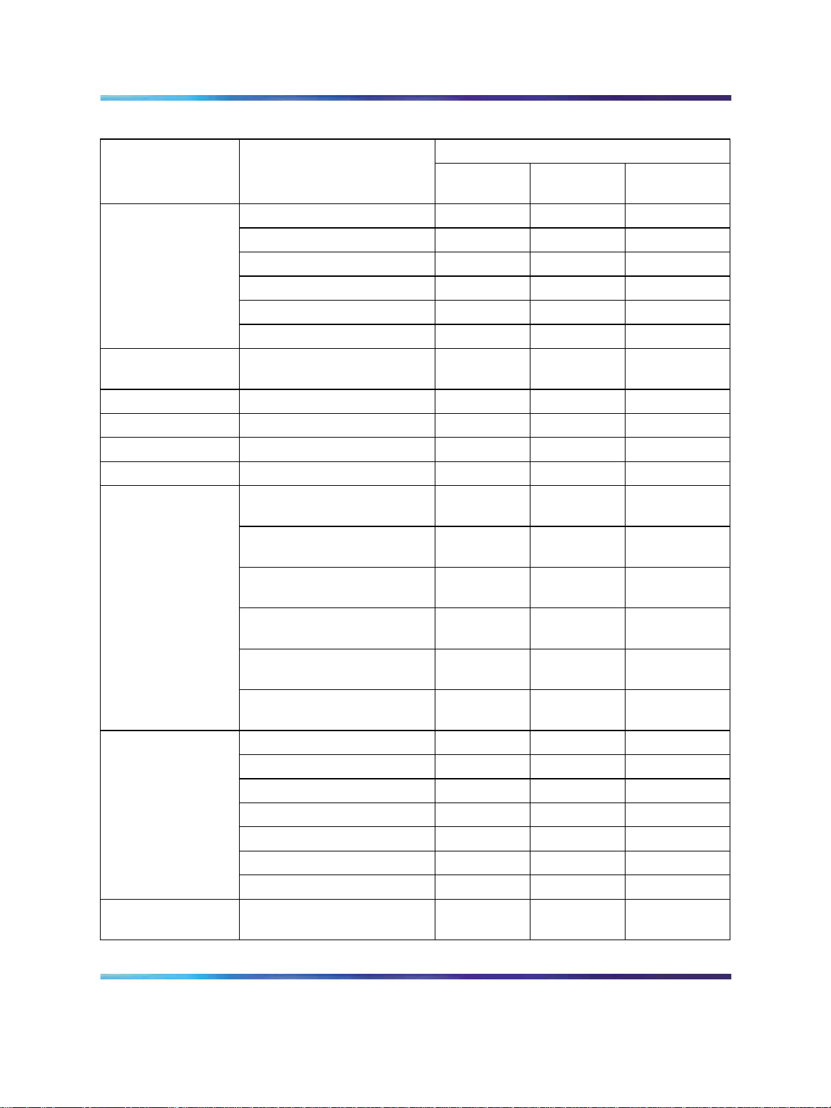
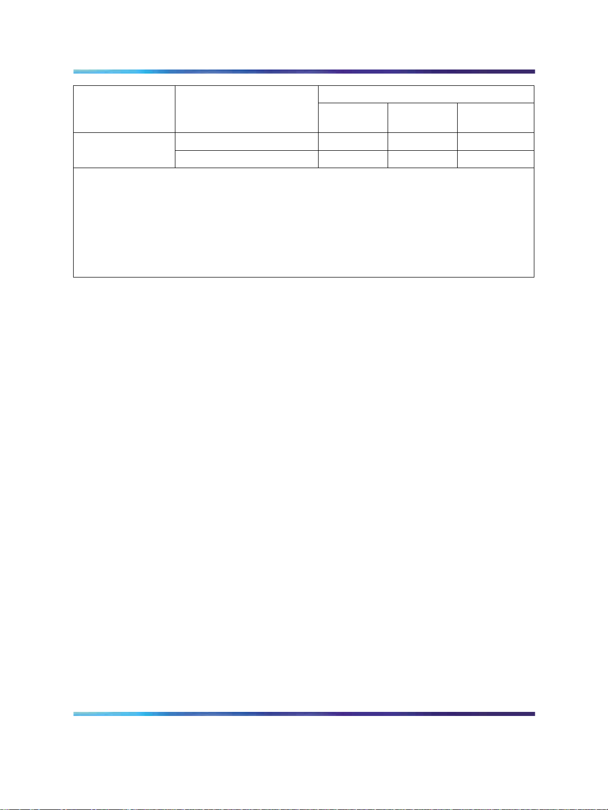
Maximum port densities for Metro Ethernet Routing Switch 8600 modules
Maximum number of ports per chassis
Module type Port type
8608GBE and
8608GBM
1000BaseSX
1000BaseLX
1000BaseZX
1000BaseXD
1000BaseCWDM
1000BaseT
8608GTE and
1000BaseT
8608GTM
8608SXE 1000BaseSX
8616GTE 1000BaseT
8616SXE 1000BaseSX
8624FXE 100BaseFX
8630GBR
1000BaseSX Not
1000BaseLX Not
1000BaseZX Not
8003 8006
8010 and
8010co
16 32 64
16 32 64
16 32 64
16 32 64
16 32 64
16 32 64
16 32 64
16 32 64
32 64 128
32 64 128
48 96 192
120 240
supported
120 240
supported
120 240
supported
1000BaseXD Not
1000BaseCWDM Not
1000BaseT Not
8632TXE and
8632TXM
10BaseT/100BaseTX
1000BaseSX
1000BaseLX
1000BaseZX
1000BaseXD
1000BaseCWDM
1000BaseT
8648GTR 10BaseT/100BaseTX/
1000BaseT
Nortel Metro Ethernet Routing Switch 8600
Copyright © 2005-2007, Nortel Networks
.
Installation — Modules
NN46220-306 02.02 Standard
supported
supported
supported
64 128 256
4816
4816
4816
4816
4816
4816
Not
supported
4.2 7 July 2008
120 240
120 240
120 240
192 384
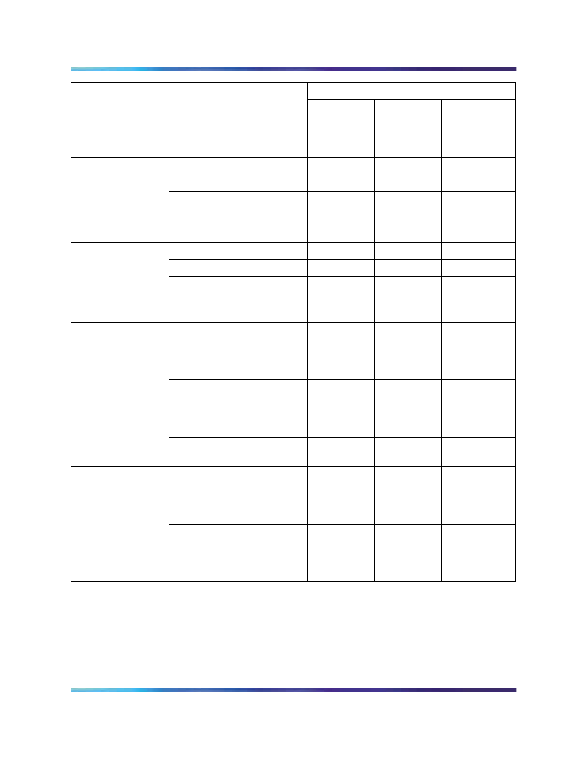
20 Metro Ethernet Routing Switch 8600 modules
Maximum number of ports per chassis
Module type Port type
8648TXE and
10BaseT/100BaseTX
8648TXM
Metro ESM 8668
(see Note 1)
1000BaseSX (SFP) NA
1000BaseLX (SFP) NA
1000BaseCWDM (SFP) NA
1000BaseT (SFP) NA
1000BaseBX (SFP) NA
8672ATME and
8672ATMM
(see Note 2)
OC-3c MDA
OC-12c MDA
DS-3 MDA
8681XLR
10-GBaseLR
(see Note 3)
8681XLW
10-GBaseLW
(see Note 3)
8683XLR
10GBaseSR Not
10GBaseLR Not
8003 8006
8010 and
8010co
96 192 384
24 56
24 56
24 56
24 56
24 56
16 32 48
4812
81624
248
248
12 24
supported
12 24
supported
10GBaseER Not
10GBaseZR Not
8683XZR
10GBaseSR Not
10GBaseLR/LW Not
10GBaseER/EW Not
10GBaseZR/ZW Not
Copyright © 2005-2007, Nortel Networks
.
12 24
supported
48
supported
12 24
supported
12 24
supported
12 24
supported
48
supported
Nortel Metro Ethernet Routing Switch 8600
Installation — Modules
NN46220-306 02.02 Standard
4.2 7 July 2008
Metro Ethernet Routing Switch 8600 R module feature set 21
Maximum number of ports per chassis
Module type Port type
8683POSM
(see Note 4)
Note 1: The 8003 chassis is not supported with Metro Ethernet Routing Switch 8600.
Note 2: For information about these Media Dependent Adapters (MDA), see "8672ATME and
8672ATMM modules" (page 50). The 8672ATME and 8672ATMM modules are not supported with
Metro Ethernet Routing Switch 8600 Ethernet VPN services.
Note 3: Metro Ethernet Routing Switch 8600 does not support the 8681XLR and 8681XLW modules.
Note 4: For information about these MDAs, see "8683POSM module" (page 56). The 8683POSM
module is not supported with Metro Ethernet Routing Switch 8600 Ethernet VPN services.
OC-3c MDA
OC-12c MDA
8003 8006
12 24 24
61212
8010 and
8010co
Metro Ethernet Routing Switch 8600 pre-E, E, and M modules feature set
Each Metro Ethernet Routing Switch 8600 pre-E, E, or M module consists
of a Backplane Forwarding Module (BFM) with common application
specific integrated circuits (ASIC) on each module. These ASICs provide a
forwarding engine and local storage of Layer 2 to 4 forwarding tables. Each
forwarding engine provides lookups, resolves addresses and sends packets
through the switch fabric to a destination port without CPU intervention. The
forwarding engine also filters packets against current prioritization policies
and can set prioritization information in the internal packet header.
The BFM is also equipped with eight priority queues per port. You can use
either of the following two prioritization schemes:
•
Strict priority
•
Weighted Round Robin (WRR)
Strict priority guarantees the highest priority. WRR gives priority based on a
round robin algorithm. For more information about prioritization schemes
see Network Design Guidelines (313197-E).
Output buffer memory consists of 8 MB of memory allocated to each Gigabit
Ethernet port or shared among eight 10/100 ports.
Note that Metro Ethernet Routing Switch 8600 does not support pre-E
modules.
Metro Ethernet Routing Switch 8600 R module feature set
Each Metro Ethernet Routing Switch 8600 R module (Release 4.0 and
later) consists of a Distributed Processing Module (DPM) as well as a Port
Interface Module (PIM). The PIM consists of various Media Access Controls
Nortel Metro Ethernet Routing Switch 8600
Copyright © 2005-2007, Nortel Networks
.
Installation — Modules
NN46220-306 02.02 Standard
4.2 7 July 2008

22 Metro Ethernet Routing Switch 8600 modules
(MAC) and Physical Layer Controls (PHY) as well as the physical interfaces
for direct network connections. A single PIM interconnects with a single
DPM to form a Metro Ethernet Routing Switch 8600 Module. Modules with
DPMs are R modules.
Metro Ethernet Routing Switch 8600 modules that use the BFM are pre-E,
E, or M modules. These modules are described in "Metro Ethernet Routing
Switch 8600 pre-E, E, and M modules feature set" (page 21).
Each DPM contains either two or three lanes, depending on the module.
Both the 8630GBR and the 8683XLR modules consist of three lanes. The
8648GTR module consists of two lanes. Each lane is also known as a
Flexible Forwarding Engine (FFE). The FFE lane is the basis for the Metro
Ethernet Routing Switch 8600 R modules. The FFE lane consists of:
•
Two FlexibleRoute Switch Processors—ingress Route Switch Processor
2 (RSP2) and egress RSP2
• One egress packet handling ASIC–F2E
•
One ingress packet handling ASIC–F2I
"Metro Ethernet Routing Switch 8600 R module packet flow on ingress and
egress" (page 22) shows the Metro Ethernet Routing Switch 8600 R module
packet flow on ingress and egress.
Metro Ethernet Routing Switch 8600 R module packet flow on ingress and
egress
The ingress RSP2 performs lookups, filtering and classification operations,
and modifies the IP and MAC headers within the body of the packet to
reflect routing and switching decisions.
Copyright © 2005-2007, Nortel Networks
.
Nortel Metro Ethernet Routing Switch 8600
Installation — Modules
NN46220-306 02.02 Standard
4.2 7 July 2008

M mode configuration requirements 23
The RSP2 determines the information the fabric needs to carry the packet
to the correct egress point and determines the physical egress port. As part
of the lookup process, the RSP2 may also determine and record the egress
queue ID and pass it to the egress RSP2.
Encapsulation is the most significant operation that the egress RSP2
performs. To specify the egress queue, the queuing and traffic shaping
functions use:
• encapsulation information from the egress RSP2
•
MAC and IP packet headers
•
Quality of Service (QoS) bits
The F2E egress ASIC supports the FFE QoS, including the functions
of random early drop, queuing and selection, traffic shaping, and
communicating to other similar R modules. Similarly, the F2I ingress ASIC
provides packet policing and marking.
Each DPM also consists of the following:
•
One Fast TAPmux (FTAP) interface to the Metro Ethernet Routing
Switch 8600 Switch Fabric Modules
•
One Feedback Output Queue Manager (FOQ) Field-Programmable
Gate Array (FPGA)
The FTAP ASIC connects each DPM to the CPU/Switch Fabric modules
through the Metro Ethernet Routing Switch 8600 switching backplane.
The FOQ Management system collects information about the state of
queues, packet storage elements, and the fabric. This information is
available to the F2I at the point at which packets are segmented for entry
to the fabric. When congestion exists, Metro Ethernet Routing Switch
8600 modules with a BFM (pre-E, E, and M modules) use fabric feedback
information only at this point to drop packets.
The FOQ mechanism also provides information about the state of each
of the egress queues and on the fullness of the F2E reassembly function
buffers and queues. The F2E reports this information to the FOQ Manager
FPGA on each module. The constellation of these FOQ FPGAs (one per
DPM) drives a shared backplane bus that each FPGA senses. Therefore,
each R module has pertinent information about the state of all other R
modules in the system.
M mode configuration requirements
M mode supports the Metro Ethernet Routing Switch 8600 M module feature
set. Full support of M mode requires the following configuration conditions:
•
The chassis must include at least one 8691omSF CPU module.
Copyright © 2005-2007, Nortel Networks
.
Nortel Metro Ethernet Routing Switch 8600
Installation — Modules
NN46220-306 02.02 Standard
4.2 7 July 2008

24 Metro Ethernet Routing Switch 8600 modules
•
All modules installed in the chassis must minimally support 128 000
table entries. M modules (8632TXM, 8648TXM, 8608GBM, 8608GTM,
8683POSM, 8672ATME, 8672ATMM, 8681XLR, and 8681XLW
modules) support 128 000 table entries.
•
M mode must be enabled.
If you enable M mode and one or more of the modules installed in the
chassis is an E module (32 000 table entries), the E modules become
disabled. This protects the system forwarding tables from losing entries.
For information about enabling or disabling M mode, see Managing
Platform Operations (315545-E).
If your system has M modules, E modules, or pre-E modules, see Managing
Platform Operations (315545-E) for information about how to configure the
switch to boot in the desired mode.
R mode configuration requirements
R mode supports the Metro Ethernet Routing Switch 8600 R module feature
set. Full support of R mode requires the following configuration conditions:
•
The system must include only R modules. You can have a system with a
mix of R, M, E, or pre-E modules configured in R mode. However, the M,
E, or pre-E modules are not enabled. For information about configuring
R modules in R mode, see Managing Platform Operations (315545-E).
•
The system must include at least one 8692omSF CPU module.
R modules do not boot with the 8691omSF CPU module.
•
R modules require Metro Ethernet Routing Switch 8600 Release 4.0
or later.
•
R mode must be enabled. For information about enabling R mode, see
Managing Platform Operations (315545-E).
If the system is currently in default mode or M mode with CPU/SF 1 as
the master and CPU/SF 2 as the standby, and you enable R mode on
CPU/SF 1, save the configuration and reboot, CPU/SF 2 comes up as
the master and CPU/SF 1 as the standby. If you then enable R mode
on the new master (CPU/SF 2), the standby (CPU/SF 1) goes offline
and remains offline.
For information about how to configure QoS, Filters, Policing, and Shaping
on R modules, see Nortel Metro Ethernet Routing Switch 8600 Configuration
— QoS and Traffic Filters (NN46220-508).
Copyright © 2005-2007, Nortel Networks
.
Nortel Metro Ethernet Routing Switch 8600
Installation — Modules
NN46220-306 02.02 Standard
4.2 7 July 2008
ESM 8668 Metro Ethernet Services Module
The ESM 8668 Metro Ethernet Services Module (Metro ESM 8668) provides
eight 1000Base SFP Gigabit Ethernet ports. The Metro ESM 8668 has the
same architecture as the Metro Ethernet Routing Switch 8600 interface
modules, but also contains an additional network processor in the data path
of each of the eight Ethernet ports.
The heart of the ESM 8668 is the flexible network processor. The network
processor contains four packet processing engines, each running at 400
megahertz (MHz). This architecture provides the flexibility, memory and
processing power to:
•
Implement a highly scalable and feature rich Ethernet VPN solution.
• Enable the highly resilient 50 millisecond (ms) Gigabit Ethernet access
ring solution with the Ethernet Services Unit (ESU) 18x0 product family.
•
Allow future feature enhancements through software upgrades.
See "ESM 8668 Metro Ethernet Services Module" (page 49) for a full
description of the Metro ESM 8668.
8608GBE and 8608GBM modules 25
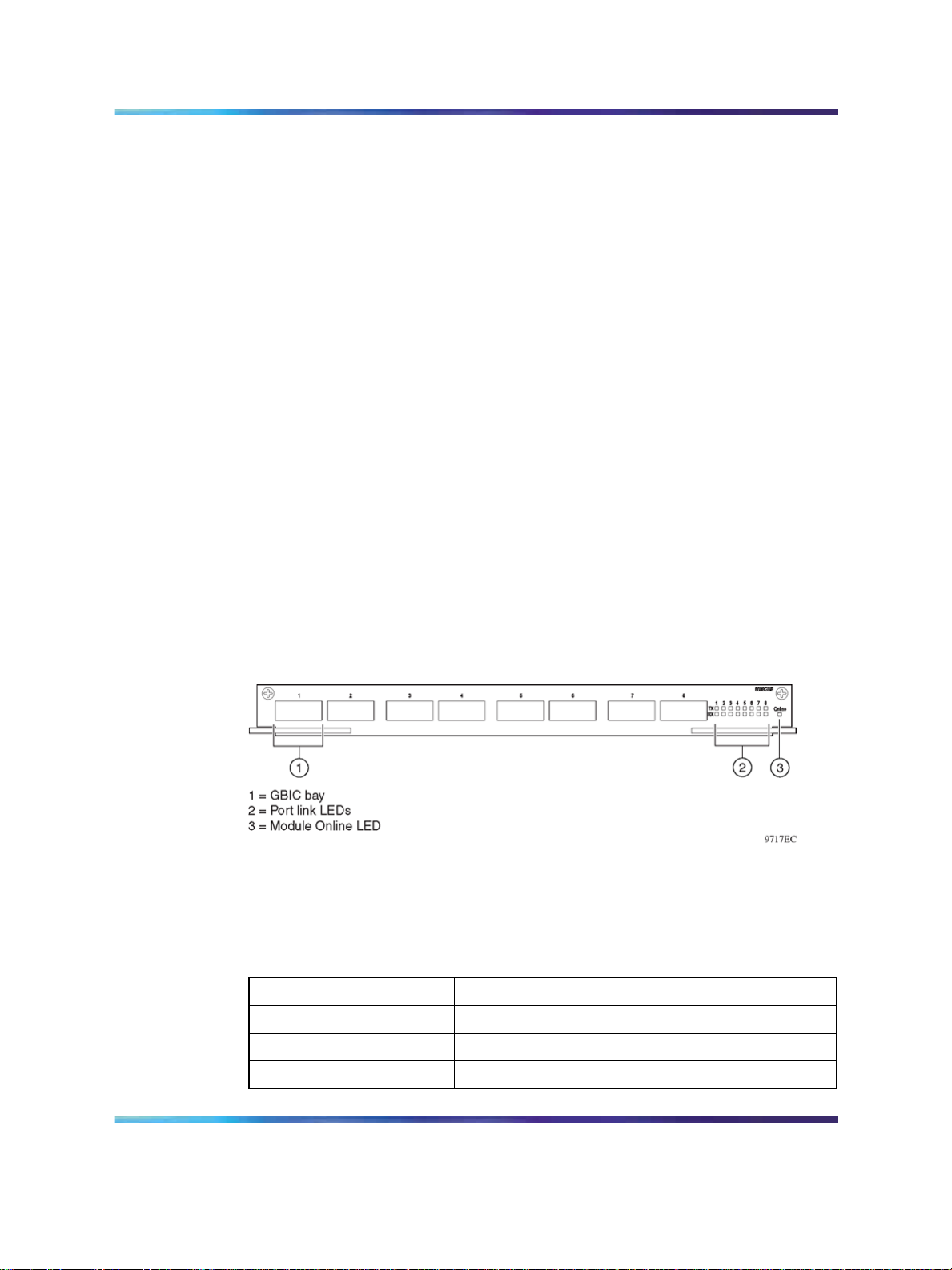
8608GBE and 8608GBM modules
Both the 8608GBE and 8608GBM modules ("8608GBE/8608GBM module"
(page 25)) provide eight bays for installing Gigabit interface converters
(GBIC). You can use the ports on the GBICs to make riser connections,
server attachments, or interswitch links.
8608GBE/8608GBM module
Nortel qualified the GBICs listed in "8608GBE and 8608GBM qualified
GBICs" (page 25) for use in the 8608GBE and 8608GBM modules:
8608GBE and 8608GBM qualified GBICs
GBIC order number GBIC type
AA1419001 1000BaseSX
AA1419002 1000BaseLX
AA1419003 1000BaseXD
Copyright © 2005-2007, Nortel Networks
.
Nortel Metro Ethernet Routing Switch 8600
Installation — Modules
NN46220-306 02.02 Standard
4.2 7 July 2008
26 Metro Ethernet Routing Switch 8600 modules
GBIC order number GBIC type
AA1419004 1000BaseZX
AA1419041 1000BaseT
AA1419017-9024 CWDM wavelengths 1470nm-1610nm
Only GBICs that Nortel qualified are supported for use in the 8608GBE
Module. GBICs that Nortel did not qualify can operate within the module,
but were not tested for power draw, electromagnetic interference, and
interoperability.
For more information about the GBICs and instructions for installing them,
see Nortel Installation — SFP, XFP, and GBIC Hardware Components
(NN46225-301).
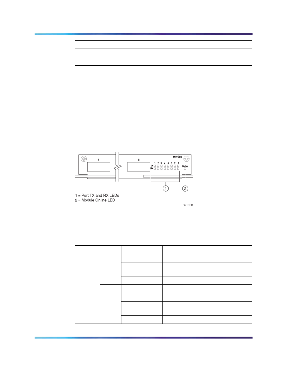
"8608GBE/8608GBM module LEDs" (page 26) shows the location of the
8608GBE and 8608GBM module LEDs.
8608GBE/8608GBM module LEDs
"8608GBE/8608GBM module LEDs" (page 26) describes the 8608GBE and
8608GBM module LEDs.
8608GBE/8608GBM module LEDs
Type Label
Port
Copyright © 2005-2007, Nortel Networks
.
Color/State
TX
RX
Nortel Metro Ethernet Routing Switch 8600
Green/Blinking The port is transmitting data.
Amber/Steady A fault condition exists on the line or on
Off The port did not detect a fault condition.
Green/Steady The port has a link and is enabled.
Green/Blinking The port is receiving data.
Amber/Steady The port has either no optical signal or
Off The port has signal but no link.
Installation — Modules
NN46220-306 02.02 Standard
4.2 7 July 2008
Meaning
the attached remote device.
no link synchronization.
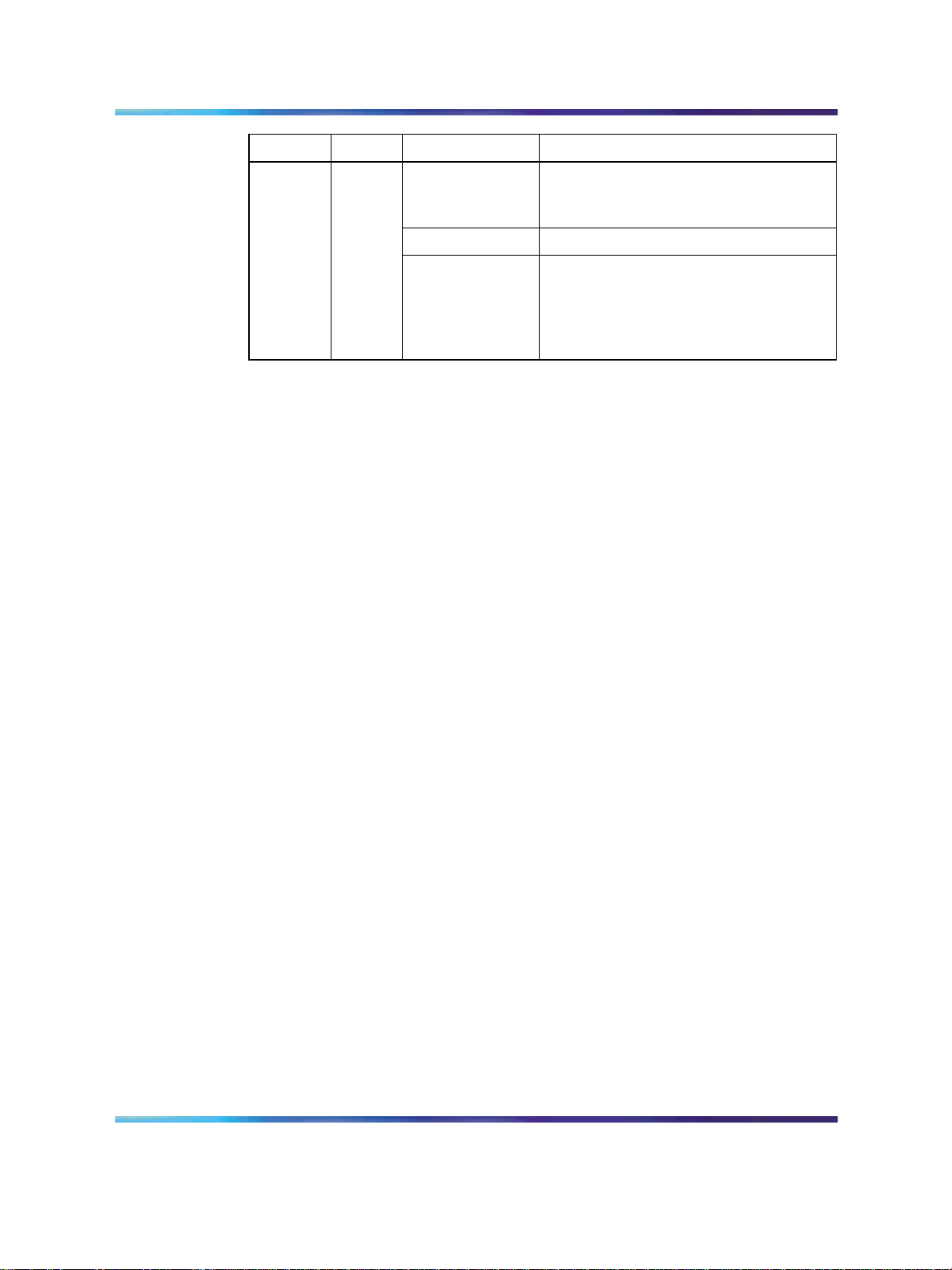
8608GTE and 8608GTM modules 27
Type Label
Module Online
Color/State
Green/Steady The module has completed its power-on
Amber/Steady The module failed its power-on self-test.
Off The switch power is off. If the switch
Meaning
self-test and software initialization and
is operating normally.
power is on, the module is going through
its power-on self-test and software
initialization. A module in this state is
not yet functional.
The 8608GBE module supports up to 32 000 table entries in its forwarding
engine. For information about table entry characteristics, see Network
Design Guidelines (313197-E).
The 8608GBM module is an M module and supports up to 128 000 table
entries in its forwarding engine, allowing for large Layer 2 and Layer 3
configurations, including Internet routing tables. For information about table
entry characteristics, see Network Design Guidelines (313197-E).
The Metro Ethernet Routing Switch 8600 system has three hardware
operating modes:
• Default mode (32 000 table entries) supports up to 32 000 hardware
records. This mode supports all modules.
•
M mode (128 000 table entries) supports up to 128 000 hardware
records. This mode supports M modules only.
•
R mode supports up to:
— 256 000 IP routes
— 64 000 MAC entries
— 32 000 Address Resolution Protocol (ARP) entries
This mode supports R modules only.
The 8608GBE module does not support R or M mode. The 8608GBM
module supports R and M mode. For specific R and M mode configuration
requirements, see "R mode configuration requirements" (page 24) and "M
mode configuration requirements" (page 23).
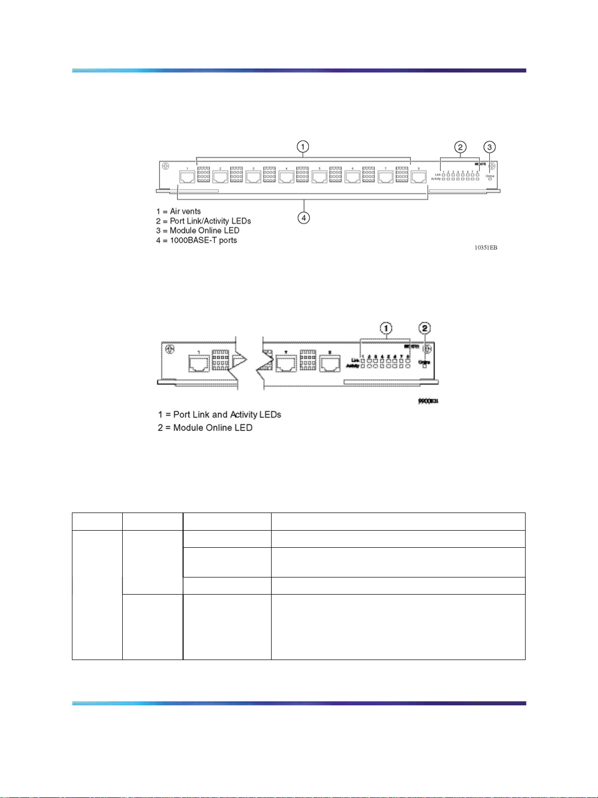
8608GTE and 8608GTM modules
Both the 8608GTE and 8608GTM module ("8608GTE/8608GTM module"
(page 28)) provide eight 1000BaseT, copper Gigabit Ethernet ports with
8-pin modular (RJ-45) connectors. Each port operates in 1000 Mb/s
(1 Gb/s) full-duplex mode and supports IEEE 802.3 1998 Clause 28
Copyright © 2005-2007, Nortel Networks
.
Nortel Metro Ethernet Routing Switch 8600
Installation — Modules
NN46220-306 02.02 Standard
4.2 7 July 2008
28 Metro Ethernet Routing Switch 8600 modules
autonegotiation and remote fault identification when the connected device
also supports autonegotiation. Distances of up to 100 meters are obtainable
with Category-5 unshielded twisted pair (UTP) cable.
8608GTE/8608GTM module
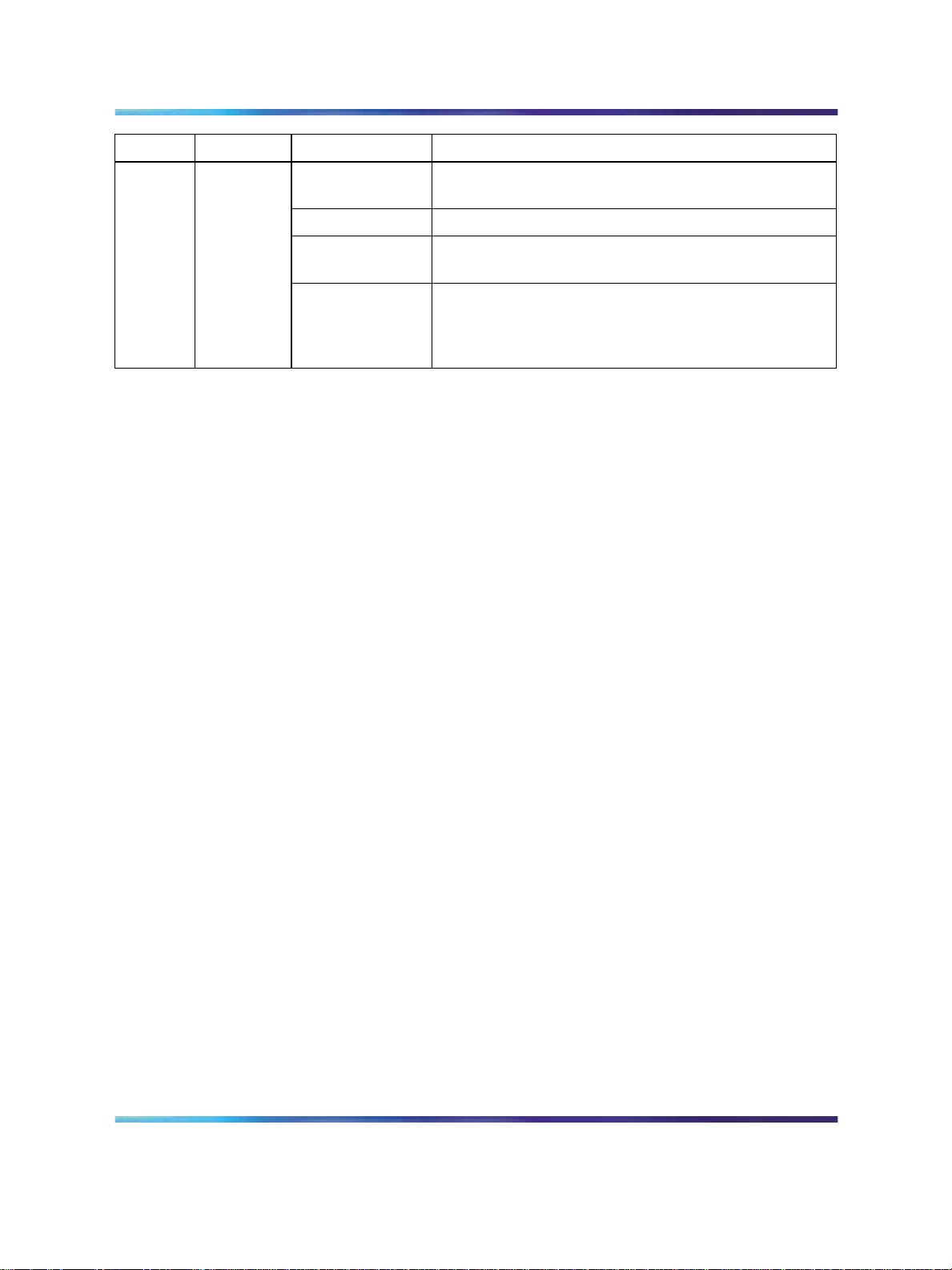
"8608GTE/8608GTM module LEDs" (page 28) shows the location of the
8608GTE and 8608GTM Module LEDs.
8608GTE/8608GTM module LEDs
"8608GTE/8608GTM module LEDs" (page 28) describes the 8608GTE
and 8608GTM module LEDs.
8608GTE/8608GTM module LEDs
Type Label
Port
Link
Activity Green/Blinking The port is receiving data.
Copyright © 2005-2007, Nortel Networks
.
Color/State
Green/Steady The port has established a link and is enabled.
Amber/Steady The port is connected, but an error condition is
Off The port is disabled or has no link.
Nortel Metro Ethernet Routing Switch 8600
Meaning
detected.
Note that as port utilization increases, this LED may
blink so fast that it appears to be steady.
Installation — Modules
NN46220-306 02.02 Standard
4.2 7 July 2008
8608GTE and 8608GTM modules 29
Type Label
Module Online
Color/State
Green/Steady The module has completed its power-on self-test and
Amber/Steady The module failed its power-on self-test.
Amber/Blinking The module has been inserted into the chassis and
Off The switch power is off. If the switch power is on, the
Meaning
software initialization and is operating normally.
diagnostics are running.
module is going through its power-on self-test and
software initialization. A module in this state is not yet
functional.
The 8608GTE module supports up to 32 000 table entries in its forwarding
engine. For information about table entry characteristics, see Network
Design Guidelines (313197-E).
The 8608GTM module is an M module and supports up to 128 000 table
entries in its forwarding engine, allowing for large Layer 2 and Layer 3
configurations, including Internet routing tables. For information about table
entry characteristics, see Network Design Guidelines (313197-E).
The Metro Ethernet Routing Switch 8600 system has three hardware
operating modes:
• Default mode (32 000 table entries) supports up to 32 000 hardware
records. This mode supports all modules.
•
M mode (128 000 table entries) supports up to 128 000 hardware
records. This mode supports M modules only.
•
R mode supports up to:
— 256 000 IP routes
— 64 000 MAC entries
— 32 000 ARP entries
This mode supports R modules only.
The 8608GTE module does not support R or M mode. The 8608GTM
module supports R and M mode. For specific R and M mode configuration
requirements, see "R mode configuration requirements" (page 24) and "M
mode configuration requirements" (page 23).
Copyright © 2005-2007, Nortel Networks
.
Nortel Metro Ethernet Routing Switch 8600
Installation — Modules
NN46220-306 02.02 Standard
4.2 7 July 2008
30 Metro Ethernet Routing Switch 8600 modules
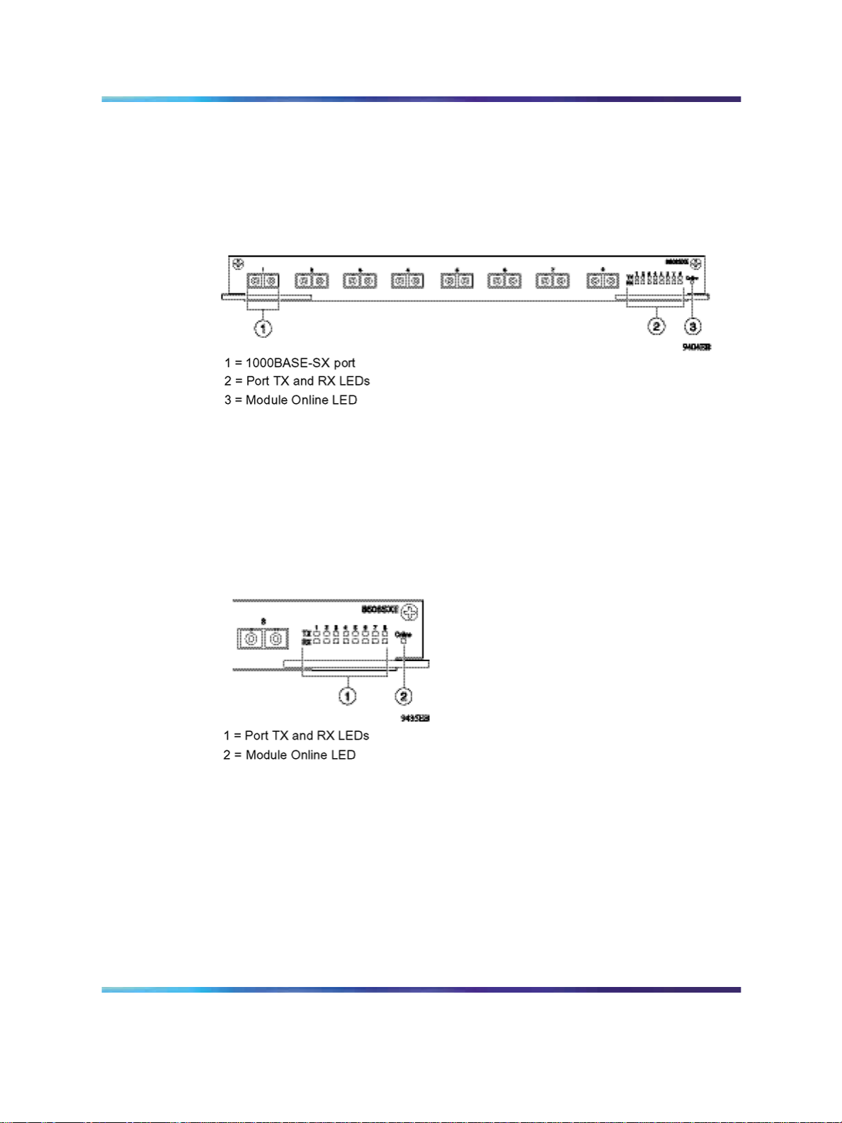
8608SXE module
The 8608SXE module ("8608SXE module" (page 30)) supports eight
1000BaseSX ports (850 nanometer [nm] shortwave,Gigabit Ethernet) using
SC type connectors for riser connections, server attachments, or interswitch
links. The 8608SXE Module supports standards-based 1000 Mb/s (1 Gb/s)
full-duplex operation only.
8608SXE module
The shortwave optical transceivers provide transmission ranges as follows:
•
Up to 275 meters (m) using 62.5 micrometers (µm) multimode fiber cable
•
Up to 550 m using 50 µm multimode fiber cable
"8608SXE module LEDs" (page 30) shows the location of the 8608SXE
module LEDs.
8608SXE module LEDs
"8608SXE module LEDs" (page 31) describes the 8608SXE module LEDs.
Copyright © 2005-2007, Nortel Networks
.
Nortel Metro Ethernet Routing Switch 8600
Installation — Modules
NN46220-306 02.02 Standard
4.2 7 July 2008

8608SXE module LEDs
8608SXE module 31
Type Label
Port
Module Online
TX
RX
Color/State
Green/Blinking The port is transmitting data.
Amber/Steady A fault condition exists on the line or on
Off The port did not detect a fault condition.
Green/Steady The port has established a link and is
Green/Blinking The port is receiving data.
Amber/Steady The port has either no optical signal or
Off The port has signal but no link.
Green/Steady The module has completed its power-on
Amber/Steady The module failed its power-on self-test.
Off The switch power is off. If the switch
Meaning
the attached remote device.
enabled.
no link synchronization.
self-test and software initialization and
is operating normally.
power is on, the module is going
through its power-on self-test and
software initialization. A module in this
state is not yet functional.
The 8608SXE module supports up to 32 000 table entries in its forwarding
engine. For information about table entry characteristics, see Network
Design Guidelines (313197-E).
The Metro Ethernet Routing Switch 8600 system has three hardware
operating modes:
•
Default mode (32 000 table entries) supports up to 32 000 hardware
records. This mode supports all modules.
•
M mode (128 000 table entries) supports up to 128 000 hardware
records. This mode supports M modules only.
•
R mode supports up to:
— 256 000 IP routes
— 64 000 MAC entries
— 32 000 ARP entries
This mode supports R modules only.
The 8608SXE module does not support R or M mode.
Copyright © 2005-2007, Nortel Networks
.
Nortel Metro Ethernet Routing Switch 8600
Installation — Modules
NN46220-306 02.02 Standard
4.2 7 July 2008

32 Metro Ethernet Routing Switch 8600 modules
8616GTE module
The 8616GTE module ("8616GTE module" (page 32)) provides 16
1000BaseT, copper Gigabit Ethernet ports with 8-pin modular (RJ-45)
connectors. Each port operates in 1000 Mb/s (1 Gb/s) full-duplex mode and
supports the IEEE 802.3ae standard. Distances of up to 100 meters are
obtainable with Category-5 unshielded twisted pair (UTP) cable.
8616GTE module
"8616GTE module LEDs" (page 32) shows the location of the 8616GTE
module LEDs.
8616GTE module LEDs
"8616GTE module LEDs" (page 32) describes the 8616GTE module LEDs.
8616GTE module LEDs
Type Label
Port
Link
Activity Green/Blinking The port is receiving data.
Color/State
Green/Steady The port has established a link and is enabled.
Amber/Steady The port is connected, but an error condition is
Off The port is disabled or has no link.
Meaning
detected.
Copyright © 2005-2007, Nortel Networks
.
Note that as port utilization increases, this LED
may blink so fast that it appears to be steady.
Nortel Metro Ethernet Routing Switch 8600
Installation — Modules
NN46220-306 02.02 Standard
4.2 7 July 2008

8616SXE module 33
Type Label
Module Online
The 8616GTE module supports up to 32 000 table entries in its forwarding
engine. For information about table entry characteristics, see Network
Design Guidelines (313197-E).
The Metro Ethernet Routing Switch 8600 system has three hardware
operating modes:
•
•
Color/State
Green/Steady The module has completed its power-on self-test
Amber/Steady The module failed its power-on self-test.
Amber/Blinking The module has been inserted into the chassis
Off The module power is off. If the switch power is
Meaning
and software initialization and is operating
normally.
and diagnostics are running.
on, the module is going through its power-on
self-test and software initialization. A module in
this state is not yet functional.
Default mode (32 000 table entries) supports up to 32 000 hardware
records. This mode supports all modules.
M mode (128 000 table entries) supports up to 128 000 hardware
records. This mode supports M modules only.
•
R mode supports up to:
— 256 000 IP routes
— 64 000 MAC entries
— 32 000 ARP entries
This mode supports R modules only.
The 8616GTE module does not support R or M mode.
8616SXE module
The 8616SXE module ("8616SXE module" (page 34)) provides 16
1000BaseSX ports (850 nm, shortwave, Gigabit Ethernet) using MT-RJ
type connectors for riser connections, server attachments, or interswitch
links. The 8616SXE module supports standards-based 1000Mb/s (1 Gb/s)
full-duplex operation only.
Copyright © 2005-2007, Nortel Networks
.
Nortel Metro Ethernet Routing Switch 8600
Installation — Modules
NN46220-306 02.02 Standard
4.2 7 July 2008

34 Metro Ethernet Routing Switch 8600 modules
8616SXE module
The shortwave optical transceivers provide transmission ranges as follows:
•
Up to 275 m using 62.5 µm multimode fiber cable
•
Up to 550 m using 50 µm multimode fiber cable
"8616SXE module LEDs" (page 34) shows the location of the 8616SXE
module LEDs.
8616SXE module LEDs
"8616SXE module LEDs" (page 34) describes the 8616SXE module LEDs.
8616SXE module LEDs
Type Label
Port
RX
Copyright © 2005-2007, Nortel Networks
.
Color/State
Green/Blinking The port is transferring data.TX
Off There is no port activity.
Green/Steady The port has established a link and is enabled.
Green/Blinking The port is receiving data.
Amber/Steady The port has either no optical signal or no link
Off The port has a signal but no link.
Meaning
synchronization.
Nortel Metro Ethernet Routing Switch 8600
Installation — Modules
NN46220-306 02.02 Standard
4.2 7 July 2008

8624FXE module 35
Type Label
Module Online
The 8616SXE module supports up to 32 000 table entries in its forwarding
engine. For information about table entry characteristics, see Network
Design Guidelines (313197-E).
The Metro Ethernet Routing Switch 8600 system has three hardware
operating modes:
•
•
• R mode supports up to:
Color/State
Green/Steady The module has completed its power-on self-test
Amber/Steady The module failed its power-on self-test.
Off The switch power is off. If the switch power is
Meaning
and software initialization and is operating
normally.
on, the module is going through its power-on
self-test and software initialization. A module in
this state is not yet functional.
Default mode (32 000 table entries) supports up to 32 000 hardware
records. This mode supports all modules.
M mode (128 000 table entries) supports up to 128 000 hardware
records. This mode supports M modules only.
— 256 000 IP routes
— 64 000 MAC entries
— 32 000 ARP entries
This mode supports R modules only.
The 8616SXE module does not support R or M mode.
8624FXE module
The 8624FXE module ("8624FXE module" (page 36)) provides 24
100BaseFX ports using MT-RJ type connectors.
Copyright © 2005-2007, Nortel Networks
.
Nortel Metro Ethernet Routing Switch 8600
Installation — Modules
NN46220-306 02.02 Standard
4.2 7 July 2008

36 Metro Ethernet Routing Switch 8600 modules
8624FXE module
The 24 100BaseFX ports on the 8624FXE module can operate in 100
Mb/s Fast Ethernet full-duplex mode. The optical transceivers provide
transmission ranges of up to 6562 ft (2 km) using 62.5 µm multimode fiber
cable or 4264 ft (1.3 km) using 50 µm multimode fiber cable.
"8624FXE module LEDs" (page 36) shows the location of the LEDs.
8624FXE module LEDs
"8624FXE module LEDs" (page 36) describes the 8624FXE module LEDs.
8624FXE module LEDs
Type Label
Port Link/Act
Copyright © 2005-2007, Nortel Networks
.
Color/State
Meaning
Green/Steady The port is connected, and the link
is good.
Green/Blinking Data is passing through this port.
Amber/Steady A fault condition exists at the far
end of the connection.
Amber/Blinking A fault condition exists at the far
end of the connection, and the port
is sending or receiving.
Off The port is not connected, or it is
connected but has no link.
Nortel Metro Ethernet Routing Switch 8600
Installation — Modules
NN46220-306 02.02 Standard
4.2 7 July 2008

8630GBR module 37
Type Label
Module Online
Color/State
Green/Steady The module has completed its
Amber/Steady The module failed its power-on
Off The switch power is off. If the
Meaning
power-on self-test and software
initialization and is operating
normally.
self-test.
switch power is on, the module
is going through its power-on
self-test and software initialization.
A module in this state is not yet
functional.
The 8624FXE module supports up to 32 000 table entries in its forwarding
engine. For information about table entry characteristics, see Network
Design Guidelines (313197-E).
The Metro Ethernet Routing Switch 8600 system has three hardware
operating modes:
•
Default mode (32 000 table entries) supports up to 32 000 hardware
records. This mode supports all modules.
•
M mode (128 000 table entries) supports up to 128 000 hardware
records. This mode supports M modules only.
•
R mode supports up to:
— 256 000 IP routes
— 64 000 MAC entries
— 32 000 ARP entries
This mode supports R modules only.
The 8624FXE module does not support R or M mode.
8630GBR module
The 8630GBR module ("8630GBR module" (page 38)) provides 30 bays
for installing small form factor pluggable (SFP) transceivers. You can use
the ports on the SFPs to make riser connections, server attachments, or
interswitch links.
The 8630GBR module is comprised of three forwarding engine lanes. Each
lane supports 10 Gb/s bidirectional traffic. All 30 ports can run concurrently
at 1 Gb/s.
Copyright © 2005-2007, Nortel Networks
.
Nortel Metro Ethernet Routing Switch 8600
Installation — Modules
NN46220-306 02.02 Standard
4.2 7 July 2008

38 Metro Ethernet Routing Switch 8600 modules
8630GBR module
Nortel qualified the SFP transceivers listed in "8630GBR qualified SFP
transceivers" (page 38) for use in the 8630GBR module:
8630GBR qualified SFP transceivers
SFP order number SFP type
AA1419013 1000BaseSX
AA1419014 1000BaseSX
AA1419015 1000BaseLX
AA1419025 - AA1419032 1000BaseCWDM
AA1419033 - AA1419040 1000BaseCWDM
AA1419042 1000BaseT
AA1419071 1000Base-EX
AA1403006 10GBASE-ZR/ZW
Only SFP transceivers that Nortel qualified are supported for use in the
8630GBR module. SFP transceivers that Nortel did not qualify can operate
within the module, but were not tested for power draw, electromagnetic
interference, and interoperability.
For more information about the SFP transceivers and instructions for
installing them, see Nortel Installation — SFP, XFP, and GBIC Hardware
Components (NN46225-301).
ATTENTION
The 8630GBR module is not supported when Single Fiber Fault Detection (SFFD)
is configured on a port.
"8630GBR module LEDs" (page 39) shows the location of the 8630GBR
module LEDs.
Copyright © 2005-2007, Nortel Networks
.
Nortel Metro Ethernet Routing Switch 8600
Installation — Modules
NN46220-306 02.02 Standard
4.2 7 July 2008

8630GBR module 39
8630GBR module LEDs
"8630GBR module LEDs" (page 39) describes the 8630GBR module LEDs.
8630GBR module LEDs
Type Label
Port
TX
RX
Color/State
Meaning
Green/Steady The port is enabled and has a link.
Green/Blinking
Port disabled.
(1 second on; 1
second off)
Green/Flashing The port is transmitting data.
The LED flash rate indicates the level
of activity on the link.
Off The port is enabled but has no link.
Green/Steady The port is enabled and has a link.
Green/Blinking
Port disabled.
(1 second on; 1
second off)
Green/Flashing The port is receiving data.
The LED flash rate indicates the level
of activity on the link.
Amber/Flashing Data error.
Copyright © 2005-2007, Nortel Networks
.
Off The port is enabled but has no link.
Nortel Metro Ethernet Routing Switch 8600
Installation — Modules
NN46220-306 02.02 Standard
4.2 7 July 2008

40 Metro Ethernet Routing Switch 8600 modules
Type Label
Module Online
Color/State
Green/Steady The module is online and is operating
Amber/Steady The module failed its power-on
Amber/Blinking The module has been inserted into the
Off The switch power is off.
Meaning
normally.
self-test.
chassis and diagnostics are running.
The 8630GBR module is an R module. When you use the 8630GBR ports
in the Enterprise mode of operation, the 8630GBR module supports the
following:
•
256 000 IP routes
•
64 000 MAC records
•
32 000 ARP records
For information about Ethernet VPN characteristics, see Engineering
Guidelines for Metro Ethernet Routing Switch 8600 and Metro Ethernet
Services Unit 1800/1850.
The Metro Ethernet Routing Switch 8600 system has three hardware
operating modes:
•
Default mode (32 000 table entries) supports up to 32 000 hardware
records. This mode supports all modules.
•
M mode (128 000 table entries) supports up to 128 000 hardware
records. This mode supports M and R modules only.
•
When used in the Enterprise mode of operation, R mode supports up to:
— 256 000 IP routes
— 64 000 MAC entries
— 32 000 ARP entries
For information about Ethernet VPN characteristics, see Engineering
Guidelines for Metro Ethernet Routing Switch 8600 and Metro Ethernet
Services Unit 1800/1850.
R mode supports R modules only.
The 8630GBR module supports R and M mode. For specific R and M mode
configuration requirements, see "R mode configuration requirements" (page
24) and "M mode configuration requirements" (page 23).
Copyright © 2005-2007, Nortel Networks
.
Nortel Metro Ethernet Routing Switch 8600
Installation — Modules
NN46220-306 02.02 Standard
4.2 7 July 2008

8632TXE and 8632TXM modules
Both the 8632TXE and 8632TXM modules ("8632TXE/8632TXM module"
(page 41)) provide 32 autonegotiating 10BaseT/100BaseTX ports using
8-pin modular (RJ-45) connectors. Ports operate at either 10 Mb/s or 100
Mb/s up to distances of 100 m with Category-3 or greater unshielded
twisted pair (UTP) cable.
Also, the modules provide two bays for 1000BaseX Gigabit Ethernet
interface connectors (GBIC).
8632TXE/8632TXM module
8632TXE and 8632TXM modules 41
The 8632TXE and 8632TXM module ports support the IEEE 802.3 1998
Clause 28 autonegotiation standard. Each port can operate in full- or
half-duplex mode. When a port is connected to another device that also
supports the IEEE 802.3 1998 Clause 28 autonegotiation standard, the
two devices negotiate the highest possible data rate and the duplex mode
of operation.
Nortel qualified the GBICs listed in "8632TXE and 8632TXM qualified
GBICs" (page 41) for use in the 8632TXE and 8632TXM modules:
8632TXE and 8632TXM qualified GBICs
GBIC order number GBIC type
AA1419001 1000BaseSX
AA1419002 1000BaseLX
AA1419003 1000BaseXD
AA1419004 1000BaseZX
AA1419041 1000BaseT
AA1419017-9024 CWDM wavelengths 1470nm-1610nm
Copyright © 2005-2007, Nortel Networks
.
Nortel Metro Ethernet Routing Switch 8600
Installation — Modules
NN46220-306 02.02 Standard
4.2 7 July 2008

42 Metro Ethernet Routing Switch 8600 modules
Only GBICs that Nortel qualified are supported for use in the 8632TXE and
8632TXM modules. GBICs that Nortel did not qualify may operate within
these modules, but have not been tested for power draw, electromagnetic
interference, and interoperability.
For more information about the GBICs and instructions for installing them,
see Nortel Installation — SFP, XFP, and GBIC Hardware Components
(NN46225-301).
"8632TXE/8632TXM module LEDs" (page 42) shows the location of the
8632TXE and 8632TXM module LEDs.
8632TXE/8632TXM module LEDs
"8632TXE/8632TXM module LEDs" (page 42) describes the 8632TXE and
8632TXM module LEDs.
8632TXE/8632TXM module LEDs
Type Label
Module Online
Color/State
Green/Steady The module has completed its
Amber/Steady The module failed its power-on
Off The switch power is off. If the
Meaning
power-on self-test and software
initialization and is operating
normally.
self-test.
switch power is on, and the module
is performing its power-on self-test
and software initialization. A
module in this state is not yet
functional.
Copyright © 2005-2007, Nortel Networks
.
Nortel Metro Ethernet Routing Switch 8600
Installation — Modules
NN46220-306 02.02 Standard
4.2 7 July 2008

8632TXE and 8632TXM modules 43
Type Label
Port
Link/Act
GBIC
TX
RX
Color/State
Green/Steady The port is operating at 100 Mb/s.10/100
Off The port is operating at 10 Mb/s.
Green/Steady The port is connected, and the link
Green/Blinking Data is passing through this port.
Off The port is disabled or has no link.
Green/Blinking The port is transmitting data.
Amber/Steady A fault condition exists on the line
Off The port did not detect a fault
Green/Steady The port has a link and is enabled.
Green/Blinking The port is receiving data.
Amber/Steady The port has either no optical signal
Off The port has a signal but no link.
Meaning
is good.
or on the attached remote device.
condition.
or no link synchronization.
The 8632TXE module supports up to 32 000 table entries in its forwarding
engine. For information about table entry characteristics, see Network
Design Guidelines (313197-E).
The 8632TXM module is an M module and supports up to 128 000 table
entries in its forwarding engine, allowing for large Layer 2 and Layer 3
configurations, including Internet routing tables. For information about table
entry characteristics, see Network Design Guidelines (313197-E).
The Metro Ethernet Routing Switch 8600 system has three hardware
operating modes:
•
Default mode (32 000 table entries) supports up to 32 000 hardware
records. This mode supports all modules.
• M mode (128 000 table entries) supports up to 128 000 hardware
records. This mode supports M modules only.
•
R mode supports up to:
— 256 000 IP routes
— 64 000 MAC entries
— 32 000 ARP entries
This mode supports R modules only.
Copyright © 2005-2007, Nortel Networks
.
Nortel Metro Ethernet Routing Switch 8600
Installation — Modules
NN46220-306 02.02 Standard
4.2 7 July 2008

44 Metro Ethernet Routing Switch 8600 modules
The 8632TXE module does not support R or M mode. The 8632TXM
module supports R and M mode. For specific R and M mode configuration
requirements, see "R mode configuration requirements" (page 24) and "M
mode configuration requirements" (page 23).
8648GTR module
The 8648GTR module ("8648GTR module" (page 44)) provides 48
10/100/1000BaseTX ports using 8-pin module (RJ-45) connectors. Each
port operates either at 10 Mb/s, 100 Mb/s, or 1000 Mb/s (1 Gb/s) and
supports the IEEE 802.3ab standard. You can obtain distances of up to 100
meters with category-5 unshielded twisted pair (UTP) cable.
8648GTR module
The 8648GTR module ports supports the IEEE 802.3 1998 Clause 28
autonegotiation standard. Each port can operate in full- or half-duplex
mode. When a port is connected to another device that also supports the
IEEE 802.3 1998 Clause 28 autonegotiation standard, the two devices
negotiate the highest possible data rate and the duplex mode of operation.
"8648GTR module LEDs" (page 44) shows the location of the 8648GTR
module LEDs.
8648GTR module LEDs
Copyright © 2005-2007, Nortel Networks
.
Nortel Metro Ethernet Routing Switch 8600
Installation — Modules
NN46220-306 02.02 Standard
4.2 7 July 2008

8648GTR module 45
"8648GTR module LEDs" (page 45) describes the 8648GTR module LEDs.
8648GTR module LEDs
Type Label
Port
Module Online
10/100/1000
Link/Activity
Color/State
Green/Steady The port is operating at
Amber/Steady The port is operating at
Off The port is operating at
Amber/Blinking Error condition.
Green/Steady The port is connected, and the
Green/Blinking Data is passing through the port.
Amber/Steady The port is administratively
Off The port has no link.
Green/Steady The module has completed its
Meaning
1000 Mb/s.
100 Mb/s.
10 Mb/s.
link is good.
The blink rate indicates the level
of link activity.
disabled.
power-on self-test and software
initialization and is operating
normally.
The 8648GTR is an R module. When 8648GTR ports are used in the
Enterprise mode of operation, it supports the following:
•
256 000 IP routes
•
64 000 MAC records
•
32 000 ARP records
For information about Ethernet VPN characteristics, see Engineering
Guidelines for Metro Ethernet Routing Switch 8600 and Metro Ethernet
Services Unit 1800/1850.
Copyright © 2005-2007, Nortel Networks
.
Amber/Steady Interimbootstate, nonoperational.
Amber/Blinking The module failed to boot.
Off The switch power is off. If
the switch power is on, the
module is going through its
power-on self-test and software
initialization. A module in this
state is not yet functional.
Nortel Metro Ethernet Routing Switch 8600
Installation — Modules
NN46220-306 02.02 Standard
4.2 7 July 2008

46 Metro Ethernet Routing Switch 8600 modules
The Metro Ethernet Routing Switch 8600 system has three hardware
operating modes:
•
Default mode (32 000 table entries) supports up to 32 000 hardware
records. This mode supports all modules.
•
M mode (128 000 table entries) supports up to 128 000 hardware
records. This mode supports M and R modules only.
•
When used in the Enterprise mode of operation, R mode supports up to:
— 256 000 IP routes
— 64 000 MAC entries
— 32 000 ARP entries
This mode supports R modules only.
For information about Ethernet VPN characteristics, see Engineering
Guidelines for Metro Ethernet Routing Switch 8600 and Metro Ethernet
Services Unit 1800/1850.
The 8648GTR module supports R and M mode. For specific R and M mode
configuration requirements, see "R mode configuration requirements" (page
24) and "M mode configuration requirements" (page 23).
8648TXE and 8648TXM modules
The 8648TXE and 8648TXM modules ("8648TXE/8648TXM module" (page
46)) provide 48 autonegotiating 10BaseT/100BaseTX ports using 8-pin
modular (RJ-45) connectors. Ports operate either at 10 Mb/s or 100 Mb/s
up to distances of 100 m with Category-3 or greater unshielded twisted
pair (UTP) cable.
8648TXE/8648TXM module
Copyright © 2005-2007, Nortel Networks
.
Nortel Metro Ethernet Routing Switch 8600
Installation — Modules
NN46220-306 02.02 Standard
4.2 7 July 2008

8648TXE and 8648TXM modules 47
Both the 8648TXE and 8648TXM module ports support the IEEE 802.3
1998 Clause 28 autonegotiation standard. Each port can operate in full- or
half-duplex mode. When a port is connected to another device that also
supports the IEEE 802.3 1998 Clause 28 autonegotiation standard, the
two devices negotiate the highest possible data rate and the duplex mode
of operation.
"8648TXE/8648TXM module LEDs" (page 47) shows the location of the
8648TXE module LEDs.
8648TXE/8648TXM module LEDs
"8648TXE/8648TXM module LEDs" (page 47) describes the 8648TXE and
8648TXM module LEDs.
8648TXE/8648TXM module LEDs
Type Label
Port
10/100
Link/Activity
Color/State
Green/Steady The port is operating at
Off The port is operating at 10 Mb/s.
Green/Steady The port is connected, and the
Green/Blinking Data is passing through the port.
Off The port is disabled or has no link.
Meaning
100 Mb/s.
link is good.
Copyright © 2005-2007, Nortel Networks
.
Nortel Metro Ethernet Routing Switch 8600
Installation — Modules
NN46220-306 02.02 Standard
4.2 7 July 2008

48 Metro Ethernet Routing Switch 8600 modules
Type Label
Module Online
Color/State
Green/Steady The module has completed its
Amber/Steady The module failed its power-on
Off The switch power is off. If
Meaning
power-on self-test and software
initialization and is operating
normally.
self-test.
the switch power is on, the
module is going through its
power-on self-test and software
initialization. A module in this
state is not yet functional.
The 8648TXE module supports up to 32 000 table entries in its forwarding
engine. For information about table entry characteristics, see Network
Design Guidelines (313197-E).
The 8648TXM module is an M module and supports up to 128 000 table
entries in its forwarding engine, allowing for large Layer 2 and Layer 3
configurations, including Internet routing tables. For information about table
entry characteristics, see Network Design Guidelines (313197-E).
The Metro Ethernet Routing Switch 8600 system has three hardware
operating modes:
•
Default mode (32 000 table entries) supports up to 32 000 hardware
records. This mode supports all modules.
•
M mode (128 000 table entries) supports up to 128 000 hardware
records. This mode supports M modules only.
•
R mode supports up to:
— 256 000 IP routes
— 64 000 MAC entries
— 32 000 ARP entries
This mode supports R modules only.
The 8648TXE module does not support R or M mode. The 8648TXM
module supports R and M mode. For specific R and M mode configuration
requirements, see "R mode configuration requirements" (page 24) and "M
mode configuration requirements" (page 23).
Copyright © 2005-2007, Nortel Networks
.
Nortel Metro Ethernet Routing Switch 8600
Installation — Modules
NN46220-306 02.02 Standard
4.2 7 July 2008

ESM 8668 Metro Ethernet Services Module 49
ESM 8668 Metro Ethernet Services Module
The ESM 8668 Metro Ethernet Services Module (Metro ESM 8668) is an
intelligent edge device with 8 bays for installing small form factor pluggable
(SFP) Gigabit Interface Converters (GBIC). You can use the Metro ESM
8668 module to create Metro Ethernet Services Unit (ESU) access rings,
optical ethernet (OE) User-to-Network Interface (UNIs), or customer IP
VLAN access points, depending on the system software configuration.
For information about installing SFPs, see Nortel Installation — SFP, XFP,
and GBIC Hardware Components (NN46225-301).
Nortel is constantly adding new models and features to existing product
lines. For a full range of SFPs and GBICs that are available from Nortel,
see your Nortel sales representative.
Refer to the latest release notes for ESM 8668 capacity information and
supported features.
Nortel qualified the SFP transceivers listed in "ESM 8668 qualified SFP
transceivers" (page 49) for use in the ESM 8668 module:
ESM 8668 qualified SFP transceivers
SFP order number SFP type
AA1419071 1000BASE-EX
For more information about the SFP transceivers and instructions for
installing them, see Nortel Installation — SFP, XFP, and GBIC Hardware
Components (NN46225-301).
"Metro ESM 8668" (page 49) shows the location of the Metro ESM 8668
bays and LEDs.
Metro ESM 8668
"Metro ESM 8668 LEDs" (page 49) describes the Metro ESM 8668 LEDs.
Metro ESM 8668 LEDs
Label
Color/State
Meaning
RX Green/Steady The link is properly synchronized and is
Copyright © 2005-2007, Nortel Networks
.
operational.
Nortel Metro Ethernet Routing Switch 8600
Installation — Modules
NN46220-306 02.02 Standard
4.2 7 July 2008

50 Metro Ethernet Routing Switch 8600 modules
Label
TX
Online
Color/State
Off No cable connection.
Amber/Steady The link is not properly synchronized.
Green/Flashing The link is passing traffic.
Off The link is not passing traffic.
Amber/Steady The link is not properly synchronized.
Green/Flashing The link is passing traffic.
Green/Steady The module is online and is load-sharing.
Amber/Steady The module failed diagnostic self-test.
Off The module is offline.
Meaning
The Metro ESM 8668 supports the following:
• 100 000 MAC entries and IP address forwarding records
•
16 000 ARP entries
Note that if the chassis is configured for R mode, the ESM 8668 module
is not supported.
8672ATME and 8672ATMM modules
Both the 8672ATME and 8672ATMM modules ("8672ATME/8672ATMM
module with an OC-12c/STM-4 MDA" (page 50)) have two bays for installing
ATM MDAs. These MDAs provide interface flexibility and ATM network
transmission that supports RFC 1483 routed and bridged PVCs. The
8672ATME and 8672ATMM modules support Synchronous Optical Network
(SONET) and Synchronous Digital Hierarchy (SDH) frame structures for
data.
8672ATME/8672ATMM module with an OC-12c/STM-4 MDA
The module requires at least one of the following MDAs:
•
1-port OC-12c/STM-4: single-mode fiber (SMF) or multimode fiber
(MMF) using the SONET or SDH media
•
4-port OC-3c/STM-1: SMF or MMF using SONET or SDH media
Copyright © 2005-2007, Nortel Networks
.
Nortel Metro Ethernet Routing Switch 8600
Installation — Modules
NN46220-306 02.02 Standard
4.2 7 July 2008

8672ATME and 8672ATMM modules 51
•
2-port DS-3
For more information about the MDAs for the 8672ATME and 8672ATMM
module, see Installing Media Dependent Adapters for the 8672ATME and
8672ATMM Modules (313071-C).
In the data center, the 8672ATME and 8672ATMM modules act as an edge
device for WAN connectivity to connect an 8600 Switch to public or private
ATM networks. In the wiring closet, this module provides inter-building
connections for campus networks where each building is supported by
frame-switched networks.
You can install up to six 8672ATME or 8672ATMM modules in one 8010
10-slot chassis. You can install up to four 8672ATME or 8672ATMM
modules in one 8006 6-slot chassis. You can install up to two 8672ATME
or 8672ATMM modules in a 8003 3-slot chassis.
Both the 8672ATME and 8672ATMM modules have an online LED that
indicates overall status for the module. "8672ATME/8672ATMM module
LED" (page 51) describes the online LED .
8672ATME/8672ATMM module LED
Color/State
Green The module is receiving power and is ready to
Amber The module is initializing and performing diagnostic
Off The module is offline and not receiving power.
Meaning
receive and transmit traffic.
self-tests.
See Using 8672ATME and 8672ATMM Modules (209195-G) for a description
of how to configure the 8672ATME and 8672ATMM modules using the
command line interface (CLI) or Device Manager.
The 8672ATME module supports up to 32 000 table entries in its forwarding
engine. For information about table entry characteristics, see Network
Design Guidelines (313197-E).
The 8672ATMM module is an M module and supports up to 128 000 table
entries in its forwarding engine, allowing for large Layer 2 and Layer 3
configurations, including Internet routing tables. For information about table
entry characteristics, see Network Design Guidelines (313197-E).
The Metro Ethernet Routing Switch 8600 system has three hardware
operating modes:
•
Default mode (32 000 table entries) supports up to 32 000 hardware
records. This mode supports all modules.
Copyright © 2005-2007, Nortel Networks
.
Nortel Metro Ethernet Routing Switch 8600
Installation — Modules
NN46220-306 02.02 Standard
4.2 7 July 2008

52 Metro Ethernet Routing Switch 8600 modules
•
M mode (128 000 table entries) supports up to 128 000 hardware
records. This mode supports M modules only.
•
R mode supports up to:
— 256 000 IP routes
— 64 000 MAC entries
— 32 000 ARP entries
This mode supports R modules only.
The 8672ATME module does not support R or M mode. The 8672ATMM
module supports R and M mode. For specific R and M mode configuration
requirements, see "R mode configuration requirements" (page 24) and "M
mode configuration requirements" (page 23).
8681XLR module
The 8681XLR module ("8681XLR module" (page 52)) provides a single
10GBaseLR 1310nm 10 Gigabit Ethernet serial LAN port. The 10GBaseLR
port (10.3 Gb/s LAN PHY) operates in full-duplex mode and provides
transmission ranges of up to 10 km using 9/125 µm single-mode fiber cable.
8681XLR module
Note that the Metro Ethernet Routing Switch 8600 does not support the
8681XLR module.
"8681XLR module LEDs" (page 53) shows the location of the 8681XLR
module LEDs.
Unlike other 8600 modules, the TX LED for the 8681XLR and 8681XLW
modules is located below the RX LED.
Copyright © 2005-2007, Nortel Networks
.
Nortel Metro Ethernet Routing Switch 8600
Installation — Modules
NN46220-306 02.02 Standard
4.2 7 July 2008

8681XLR module LEDs
"8681XLR module LEDs" (page 53) describes the 8681XLR module LEDs.
8681XLR module LEDs
8681XLR module 53
Type Label
Port
TX
RX
Module Online
Color/State
Meaning
Green/Steady The port is enabled but not
transmitting data.
Green/Blinking The port is transmitting data.
Off The port transmit is disabled.
Green/Steady The port has a link and is enabled.
Green/Blinking The port is receiving data.
Amber/Steady The cable is disconnected, the port
is disabled, or the link is down.
Green/Steady The module has completed its
power-on self-test and software
initialization and is operating
normally.
Amber/Steady The module slot is disabled.
Off The switch power is off. If the
switch power is on, the module
is going through its power-on
self-test and software initialization.
A module in this state is not yet
functional.
See Using Metro Ethernet Routing Switch 8600 10 Gigabit Ethernet
Modules (315893-E) for a description of how to configure the 8681XLR
module using the command line interface (CLI) or Device Manager.
Copyright © 2005-2007, Nortel Networks
.
Nortel Metro Ethernet Routing Switch 8600
Installation — Modules
NN46220-306 02.02 Standard
4.2 7 July 2008

54 Metro Ethernet Routing Switch 8600 modules
The 8681XLR module supports up to 128 000 table entries in its forwarding
engine, allowing for large Layer 2 and Layer 3 configurations, including
Internet routing tables. For information about table entry characteristics, see
Network Design Guidelines (313197-E).
The Metro Ethernet Routing Switch 8600 system has three hardware
operating modes:
•
Default mode (32 000 table entries) supports up to 32 000 hardware
records. This mode supports all modules.
•
M mode (128 000 table entries) supports up to 128 000 hardware
records. This mode supports M modules only.
•
R mode supports up to:
— 256 000 IP routes
— 64 000 MAC entries
— 32 000 ARP entries
This mode supports R modules only.
The 8681XLR module supports R and M mode. For specific R and M mode
configuration requirements, see "R mode configuration requirements" (page
24) and "M mode configuration requirements" (page 23).
8681XLW module
The 8681XLW module ("8681XLW module" (page 54)) provides a
single 10GBaseLW 1310nm 10 Gigabit Ethernet serial WAN port. The
10GBaseLW port (9.95 Gb/s WAN PHY) operates in full-duplex mode and
provides a transmission range of up to 10 km using 9/125 µm single-mode
fiber cable.
Note that the Metro Ethernet Routing Switch 8600 does not support the
8681XLW module.
8681XLW module
Copyright © 2005-2007, Nortel Networks
.
Nortel Metro Ethernet Routing Switch 8600
Installation — Modules
NN46220-306 02.02 Standard
4.2 7 July 2008

"8681XLW module LEDs" (page 55)shows the location of the 8681XLW
module LEDs.
Unlike other 8600 modules, the TX LED for the 8681XLR and 8681XLW
modules is located below the RX LED.
8681XLW module LEDs
"8681XLW module LEDs" (page 55) describes the 8681XLW module LEDs.
8681XLW module 55
8681XLW module LEDs
Type Label
Port
TX
RX
Module Online
Color/State
Meaning
Green/Blinking The port is transmitting data.
Green/Steady The port is enabled but not
transmitting data.
Off The port did not detect a fault
condition.
Green/Steady The port has a link and is enabled.
Green/Blinking The port is receiving data.
Amber/Steady The cable is disconnected, the port
is disabled, the link is down, or
SONET errors are detected.
Green/Steady The module has completed its
power-on self-test and software
initialization and is operating
normally.
Amber/Steady The module slot is disabled.
Off The switch power is off. If the
switch power is on, the module
is going through its power-on
self-test and software initialization.
A module in this state is not yet
functional.
Copyright © 2005-2007, Nortel Networks
.
Nortel Metro Ethernet Routing Switch 8600
Installation — Modules
NN46220-306 02.02 Standard
4.2 7 July 2008

56 Metro Ethernet Routing Switch 8600 modules
See Using Metro Ethernet Routing Switch 8600 10 Gigabit Ethernet
Modules (315893-E) for a description of how to configure the 8681XLW
module using the command line interface (CLI) or Device Manager.
The 8681XLW module supports up to 128 000 table entries in its forwarding
engine, allowing for large Layer 2 and Layer 3 configurations, including
Internet routing tables. For information about table entry characteristics, see
Network Design Guidelines (313197-E).
The Metro Ethernet Routing Switch 8600 system has three hardware
operating modes:
•
Default mode (32 000 table entries) supports up to 32 000 hardware
records. This mode supports all modules.
•
M mode (128 000 table entries) supports up to 128 000 hardware
records. This mode supports M modules only.
•
R mode supports up to:
— 256 000 IP routes
— 64 000 MAC entries
— 32 000 ARP entries
This mode supports R modules only.
The 8681XLW module supports R and M mode. For specific R and M mode
configuration requirements, see "R mode configuration requirements" (page
24) and "M mode configuration requirements" (page 23).
8683POSM module
The 8683POSM module ("8683POSM module with an OC-12c/STM-4 MDA"
(page 56)) has three bays for installing POS media dependent adapters
(MDAs). These MDAs provide MAN/WAN support by allowing access
to SONET services in the metropolitan area. You can connect multiple
campuses in a single metropolitan area without compromising performance
or increasing complexity. You can install up to four 8683POSM modules in
one 8010 10-slot chassis (four in a 8006 6-slot chassis, and two in a 8003
3-slot chassis).
8683POSM module with an OC-12c/STM-4 MDA
Copyright © 2005-2007, Nortel Networks
.
Nortel Metro Ethernet Routing Switch 8600
Installation — Modules
NN46220-306 02.02 Standard
4.2 7 July 2008

8683POSM module 57
To operate, each module requires at least one of the following MDAs:
•
1-port OC-12c/STM-4: SMF or MMF using SONET media
•
2-port OC-3c/STM-1: SMF or MMF using SONET media
The 8683POSM module supports a mixture of OC-3c/STM-1 and
OC-12c/STM-4 lines. For example, you can install an OC-12c/STM-4
MDA in the first bay and OC-3c/STM-1 MDAs in the two remaining bays.
This module supports up to six I/O OC-3c/STM-1 lines and up to three I/O
OC-12c/STM-4 lines.
The 8683POSM module has an online LED that indicates overall status for
the module. "8683POSM module LED" (page 57) describes the online LED.
8683POSM module LED
Color/State
Green The module is receiving power and is ready to receive
Amber The module is initializing and performing diagnostic
Off The module is offline and is not receiving power.
Meaning
and transmit traffic.
self-tests.
See Using the 8683POSM Module (209564-C) for a description of how to
configure the 8683POSM module using the command line interface (CLI)
or Device Manager.
The 8683POSM module is an M module and supports up to 128 000 table
entries in its forwarding engine, allowing for large Layer 2 and Layer 3
configurations, including Internet routing tables. For information about table
entry characteristics, see Network Design Guidelines (313197-E).
The Metro Ethernet Routing Switch 8600 system has three hardware
operating modes:
•
Default mode (32 000 table entries) supports up to 32 000 hardware
records. This mode supports all modules.
• M mode (128 000 table entries) supports up to 128 000 hardware
records. This mode supports M modules only.
•
R mode supports up to:
— 256 000 IP routes
— 64 000 MAC entries
— 32 000 ARP entries
This mode supports R modules only.
Copyright © 2005-2007, Nortel Networks
.
Nortel Metro Ethernet Routing Switch 8600
Installation — Modules
NN46220-306 02.02 Standard
4.2 7 July 2008

58 Metro Ethernet Routing Switch 8600 modules
The 8683POSM module supports R and M mode. For specific R and M
mode configuration requirements, see "R mode configuration requirements"
(page 24) and "M mode configuration requirements" (page 23).
8683XLR module
The 8683XLR module ("8683XLR module" (page 58)) provides three
bays for installing 10 Gigabit Ethernet small form factor pluggable (XFP)
transceivers. The 10GBaseR port (10.3 Gb/s LAN PHY) operates in
full-duplex mode and provides transmission ranges of up to 10 km using
9/125 µm single-mode fiber cable.
The 8683XLR module is comprised of three forwarding engine lanes.
Each lane supports 10 Gb/s bidirectional traffic. All three ports may run
concurrently at 10 Gb/s.
Nortel recommends that you install only one 10GBaseZR/ZW on the 8683XLR
and 8683XZR due to cooling limitations. Nortel further recommends that you
install the XFP only in port 1. You can install a 10GBaseSR, -LR/LW, or -ER/EW
in one or both of the remaining ports.
ATTENTION
8683XLR module
The 8683XLR module supports up to three 10 Gigabit Ethernet small form
factor pluggable (XFP) transceivers.
Although some of the XFPs are LAN/WAN (that is, LR/LW, ER/EW, ZR/ZW)
this module only makes use of the LAN functionality.
Nortel qualified the XFPs listed in "8683XLR qualified XFP transceivers"
(page 58).
8683XLR qualified XFP transceivers
XFP order number XFP type
AA1403005 10GBaseSR
AA1403001 10GBaseLR
Copyright © 2005-2007, Nortel Networks
.
Nortel Metro Ethernet Routing Switch 8600
Installation — Modules
NN46220-306 02.02 Standard
4.2 7 July 2008

8683XLR module 59
XFP order number XFP type
AA1403003 10GBaseER
AA1403006 10GBaseZR
"8683XLR module LEDs" (page 59) shows the location of the 8683XLR
module LEDs.
8683XLR module LEDs
"8683XLR module LEDs" (page 59) describes the 8683XLR module LEDs.
8683XLR module LEDs
Type Label
Port
TX
RX
TX & RX Both Blinking
Color/State
Meaning
Green/Steady The port isenabledbutnottransmitting
data.
Green/Blinking The port is transmitting data.
Off The cable is disconnected or the link
is down.
Green/Steady The port has a link and is enabled.
Green/Blinking The port is receiving data.
Off The cable is disconnected or the link
is down.
The port is disabled.
Green
Copyright © 2005-2007, Nortel Networks
.
Nortel Metro Ethernet Routing Switch 8600
Installation — Modules
NN46220-306 02.02 Standard
4.2 7 July 2008

60 Metro Ethernet Routing Switch 8600 modules
Type Label
Module Online
Color/State
Green/Steady The module has completed its
Amber/Steady The module slot is disabled or in the
Off The switch power is off or there is no
Meaning
power-on self-test and software
initialization and is operating normally.
process of software initialization.
power to the card. If the switch power
is on, the module is going through
its power-on self-test and software
initialization. A module in this state is
not yet functional.
See Using Metro Ethernet Routing Switch 8600 10 Gigabit Ethernet
Modules (315893-E) for a description of how to configure the 8683XLR
module using the command line interface (CLI) or Device Manager.
The Ethernet Routing Switch 8683XLR module is an R module. When
8683XLR ports are used in the Enterprise mode of operation, it supports
the following:
•
256 000 IP routes
•
64 000 MAC records
• 32 000 ARP records
For information about Ethernet VPN characteristics, see Engineering
Guidelines for Metro Ethernet Routing Switch 8600 and Metro Ethernet
Services Unit 1800/1850.
The Metro Ethernet Routing Switch 8600 system has three hardware
operating modes:
• Default mode (32 000 table entries) supports up to 32 000 hardware
records. This mode supports all modules.
•
M mode (128 000 table entries) supports up to 128 000 hardware
records. This mode supports M and R modules only.
•
When used in the Enterprise mode of operation, R mode supports up to:
— 256 000 IP routes
— 64 000 MAC entries
— 32 000 ARP entries
For information about Ethernet VPN characteristics, see Engineering
Guidelines for Metro Ethernet Routing Switch 8600 and Metro Ethernet
Services Unit 1800/1850.
Copyright © 2005-2007, Nortel Networks
.
Nortel Metro Ethernet Routing Switch 8600
Installation — Modules
NN46220-306 02.02 Standard
4.2 7 July 2008

R mode supports R modules only.
The 8683XLR module supports R and M mode. For specific R and M mode
configuration requirements, see "R mode configuration requirements" (page
24) and "M mode configuration requirements" (page 23).
8683XZR module
The 868XZR module supports both LAN and WANoperation (10.3 Gb/s LAN
PHY and 9.9 Gb/s WAN PHY). The 8683XZR module ("8683XZR module"
(page 61)) provides three bays for installing 10 Gigabit Ethernet small form
factor pluggable (XFP) transceivers. The port operates in full-duplex mode.
The 8683XZR module includes three forwarding engine lanes. Each lane
supports 10 Gb/s bidirectional traffic. All three ports can run concurrently
at 10 Gb/s.
Nortel recommends that you install only one 10GBaseZR/ZW on the 8683XLR
and 8683XZR due to cooling limitations. Nortel further recommends that you
install the XFP only in port 1. You can install a 10GBaseSR, -LR/LW, or -ER/EW
in one or both of the remaining ports.
8683XZR module 61
ATTENTION
8683XZR module
The 8683XZR module supports up to three 10 Gigabit Ethernet small form
factor pluggable (XFP) transceivers.
Nortel qualified the XFPs listed in "8683XZR qualified XFPs" (page 61).
8683XZR qualified XFPs
XFP order number XFP type
AA1403005 10GBaseSR/SW
AA1403001 10GBaseLR/LW
AA1403003 10GBaseER/EW
AA1403006 10GBaseZR/ZW
Copyright © 2005-2007, Nortel Networks
.
Nortel Metro Ethernet Routing Switch 8600
Installation — Modules
NN46220-306 02.02 Standard
4.2 7 July 2008

62 Metro Ethernet Routing Switch 8600 modules
"8683XZR Module LEDs" (page 62) shows the location of the 8683XZR
Module LEDs.
8683XZR Module LEDs
" 8683XZR Module LEDs" (page 62) describes the 8683XZR Module LEDs.
8683XZR Module LEDs
Type Label
Port
Module Online
TX
RX
Color/State
Green/Steady The port is enabled but not transmitting
Green/Blinking The port is transmitting data.
Off The port is disabled.
Green/Steady The port has a link and is enabled.
Green/Blinking The port is receiving data.
Amber/Steady The cable is disconnected, the port is
Green/Steady The module completed its power-on
Amber/Steady The module slot is disabled.
Off The switch power is off. If the switch
Meaning
data.
disabled, or the link is down.
self-test and software initialization and
is operating normally.
power is on, the module is going
through its power-on self-test and
software initialization. A module in this
state is not yet functional.
See Using Metro Ethernet Routing Switch 8600 10 Gigabit Ethernet
Modules (315893-E) for a description of how to configure the 8683XZR
Module using the command line interface (CLI) or Device Manager.
The 8683XZR module is an R module. When 8683XZR ports are used in
the Enterprise mode of operation, it supports the following:
•
256 000 IP routes
• 64 000 MAC records
Copyright © 2005-2007, Nortel Networks
.
Nortel Metro Ethernet Routing Switch 8600
Installation — Modules
NN46220-306 02.02 Standard
4.2 7 July 2008

8691omSF module 63
•
32 000 ARP records
For information about Ethernet VPN characteristics, see Engineering
Guidelines for Metro Ethernet Routing Switch 8600 and Metro Ethernet
Services Unit 1800/1850.
The Metro Ethernet Routing Switch 8600 system has three hardware
operating modes:
•
Default mode (32 000 table entries) supports up to 32 000 hardware
records. This mode supports all modules.
•
M mode (128 000 table entries) supports up to 128 000 hardware
records. This mode supports M and R modules only.
•
When used in the Enterprise mode of operation, R mode supports up to:
— 256 000 IP routes
— 64 000 MAC entries
— 32 000 ARP entries
For information about Ethernet VPN characteristics, see Engineering
Guidelines for Metro Ethernet Routing Switch 8600 and Metro Ethernet
Services Unit 1800/1850.
R mode supports R modules only.
The 8683XZR module supports R and M mode. For specific R and M mode
configuration requirements, see "R mode configuration requirements" (page
24) and "M mode configuration requirements" (page 23).
8691omSF module
The 8691omSF module ("8691omSF module" (page 63)) provides the core
switching fabric for the Metro Ethernet Routing Switch 8600, as well as a
CPU subsystem and a real-time clock. The core switching fabric switches all
traffic through the routing switch modules. The CPU subsystem manages
the routing switch fabric and the other I/O modules.
8691omSF module
Copyright © 2005-2007, Nortel Networks
.
Nortel Metro Ethernet Routing Switch 8600
Installation — Modules
NN46220-306 02.02 Standard
4.2 7 July 2008

64 Metro Ethernet Routing Switch 8600 modules
The 8691SF/256 (DS1404090) is functionally identical to the 8691SF except
it has 256 MB of synchronous dynamic random access memory (SDRAM)
installed. The 8691SF/256 is identified by the front panel model number
label in the upper right corner as 8691SF/256.
You can use the 8691SF as a Metro Ethernet switch fabric with the
appropriate memory upgrade. See Installing a CPU Memory Upgrade
(314832-D) for instructions for upgrading CPU memory.
The 8691omSF module consists of a printed circuit board with status LEDs,
a management port, a DCE/DTE switch for the console port, a console port,
a modem port, a reset button, and a PC Card slot.
The CPU subsystem uses a PowerPC CPU and has 256 MB of SDRAM.
The 8691omSF module contains 16 MB of onboard flash memory used to
store the image file, and 2 MB of boot memory (ROM).
The routing switch fabric uses 10 MB of shared, high-speed memory. This
memory buffers traffic destined for I/O modules. The switch logic allocates
memory to the various switch priority queues according to traffic usage and
current switch configuration.
In all 8000 series chassis other than the 8003 chassis, you can install a
8691omSF module in both slots 5 and 6 of the chassis to enable redundant
operation. The redundant module in slot 6 can assume the processing
duties of a failing primary 8691omSF module in slot 5.
When the 8691omSF module in slot 6 completes initialization, it relearns the
routing and VLAN bridging information for the switch unless the HA-CPU
flag is enabled. If HA-CPU is enabled, the static routes and ARP entries
for routing are synchronized to the redundant CPU, which results in no
interruption of network services.
The two 8691omSF modules share switch fabric functions for the switch. If
one 8691omSF module fails, the system reverts to operation with a single
8691omSF module.
Note that when the Metro ESM 8668 module is installed, the HA-CPU flag
is not supported.
"8691omSF module LEDs" (page 65) shows the location of the 8691omSF
module LEDs.
Copyright © 2005-2007, Nortel Networks
.
Nortel Metro Ethernet Routing Switch 8600
Installation — Modules
NN46220-306 02.02 Standard
4.2 7 July 2008

8691omSF module 65
8691omSF module LEDs
The Switch LEDs and the CPU LEDs serve as a bar graph to indicate card
activity. The Switch bar graph increases as the switch fabric utilization
increases. The CPU bar graph increases when the CPU is actively
performing tasks, such as learning media access control (MAC) addresses,
updating routing tables, or interacting with the device management station.
"8691omSF module LEDs" (page 65) describes the 8691omSF module
LEDs.
8691omSF module LEDs
Label
Color/State
Mz N/A Reserved for future use.
Link
Green/Steady The management port is connected, and the
Off There is no link to the management port.
100
Green/Steady Themanagement port is operating at 100 Mb/s.
Off The management port is operating at 10 Mb/s.
Switch
Green
Utilization
(8 LEDs)
Meaning
link is good.
The number of lit LEDs indicates the utilization
level of the switch fabric as follows:
1 LED = 10 Mb/s 5 LEDs = 10 Gb/s
2 LEDs = 100 Mb/s 6 LEDs = 20 Gb/s
3 LEDs = 1 Gb/s 7 LEDs = 40 Gb/s
4 LEDs = 5 Gb/s 8 LEDs = 64 Gb/s
Copyright © 2005-2007, Nortel Networks
.
Nortel Metro Ethernet Routing Switch 8600
Installation — Modules
NN46220-306 02.02 Standard
4.2 7 July 2008

66 Metro Ethernet Routing Switch 8600 modules
Label
CPU
Utilization
(8 LEDs)
Power
Supply
1, 2, 3
Fan 1, 2
Master
Color/State
Green
Meaning
The number of lit LEDs indicates the level of
CPU activity as follows:
1 LED = 12% 5 LEDs = 60%
2 LEDs = 24% 6 LEDs = 72%
3 LEDs = 36% 7 LEDs = 84%
4 LEDs = 48% 8 LEDs = 100%
Green/Steady The specified power supply is operating
normally.
Amber/Steady The specified power supply has a fault.
Off A power supply is not present in the specified
bay, or the power supply in the specified bay
is not turned on.
Green/Steady The specified fan is operating normally.
Amber/Steady The specified fan has failed.
Green/Steady The temperature is normal for switch operation.Temp
Amber/Steady The temperature of the switch has exceeded
the maximum operating temperature.
Green/Steady The CPU subsystem on the module is
performing diagnostics.
Green/Blinking This module is providing active CPU functions
Amber/Steady The CPU subsystem is in a fault state.
Off The CPU subsystem on the module is up and
Online
Green/Steady Theswitch fabric portion of the module is online
Amber/Steady The switch fabric portion of the module failed
Off The switch fabric portion of the module is
Ethernet management port
Ethernet management port on the 8691omSF module is an MDI
10/100BaseT port that allows out-of-band management of the switch
using a Web browser or Device Manager. You can also establish a Telnet
session to access the CLI. Use this port to connect the switch to a network
management station. The Ethernet management port has its own IP
address but does not switch traffic to other ports in the chassis.
for the switch and is the master CPU module.
is in standby mode.
and is load-sharing.
diagnostics.
offline.
Copyright © 2005-2007, Nortel Networks
.
Nortel Metro Ethernet Routing Switch 8600
Installation — Modules
NN46220-306 02.02 Standard
4.2 7 July 2008

Note that you use this port only as a management port. This port provides
out-of-band management for the 8691omSF module.
DCE/DTE switch
The DCE/DTE switch changes the pin assignments on the Console port.
Use this switch to designate the connector as either DTE or DCE. For
information about pin assignments for the Console port, see "Console serial
port" (page 130).
Serial ports
The 8691omSF module provides two serial ports for attaching modem and
console devices. You can use the console port to access the 8691omSF
module with a terminal using the CLI. Use the modem port to connect a
standard modem for out-of-band, dial-up management. For information
about pin assignments for these ports, see "Console serial port" (page
130) and "Modem serial port" (page 130).
Reset button
Use the recessed Reset button on the module to perform a hard reset or
reboot of the system.
8692omSF module 67
PC Card slot
The PC Card slot in the 8691omSF module accepts an ATA-type,
SanDisk-compatible flash memory card. This memory card provides a
convenient way to store switch configurations and boot images. Using a
memory card, you can quickly transfer configurations and images between
switches or store multiple configurations for a single switch.
Supported memory cards for the 8691omSF module include the following:
•
Modem cards that are compatible with Intel 8250 or National 16552
serial ports
•
LAN cards from 3COM 589, 562, or 556 equipment.
8692omSF module
Dual 8692omSF switch fabric modules ("8692omSF module" (page 68))
enable a maximum switch bandwidth of 512 Gb/s. Using the Split MultiLink
Trunking (SMLT) protocol in the core, a redundant Metro Ethernet Routing
Switch 8600 with two 8692omSF modules can provide over 1 terabit per
second (Tb/s) of core switching capacity.
Copyright © 2005-2007, Nortel Networks
.
Nortel Metro Ethernet Routing Switch 8600
Installation — Modules
NN46220-306 02.02 Standard
4.2 7 July 2008

68 Metro Ethernet Routing Switch 8600 modules
8692omSF module
Do not use any software prior to Metro Ethernet Routing Switch 8600
Release 3.6 with the 8692omSF CPU module. For more information, see
Nortel Metro Ethernet Routing Switch 8600 Important Notice — Using the
Correct Software Version for the 8692SF CPU Module (NN46220-404).
The 8692SF module is equivalent to the 8692omSF module. It can be used
as Metro Ethernet switch fabric with the appropriate software. See Nortel
Metro Ethernet Routing Switch 8600 Important Notice — Using the Correct
Software Version for the 8692SF CPU Module (NN46220-404).
The 8692omSF module uses a CPU similar to the PowerPC CPU of the
8691omSF. The 8692omSF CPU has 256 MB of synchronous dynamic
random access memory (SDRAM) for forwarding tables, and 56 MB of
onboard flash memory for configuration, image and log file storage.
The 8692omSF is capable of supporting an optional Metro Ethernet
enhanced CPU daughter card. The Metro Ethernet enhanced CPU
daughter card is a mezzanine daughter card consisting of dual 1 GHz
PowerPC processors. Installing the daughter card on an 8692omSF module
offloads processor intensive tasks from the 333 MHz processor located on
the 8692omSF CPU motherboard. The Metro Ethernet enhanced CPU
daughter card is required for Provider Backbone Transport (PBT) services.
For installation instructions, see Appendix "Installing the Metro Ethernet
enhanced CPU daughter card" (page 135).
The flash memory is divided into two volumes: Volume/0 has a capacity of
16 MB and Volume/1 has a capacity of 40 MB. You can use either volume
to store multiple file types, however, the 8692omSF module can only use
either Volume/0 or Volume/1. By default, the system can only use 16 MB on
Volume/0. If you want to use 40 MB on Volume/1, refer to the procedure
for upgrading the flash memory to 40 MB in Nortel Metro Ethernet Routing
Switch 8600 Upgrading — Software Release 4.1 (NN46220-402).
Using the SMLT protocol in the core, the Metro Ethernet Routing Switch
8600 can provide over 1 Tb/s of core switching capability.
Copyright © 2005-2007, Nortel Networks
.
Nortel Metro Ethernet Routing Switch 8600
Installation — Modules
NN46220-306 02.02 Standard
4.2 7 July 2008

LEDs
8692omSF module 69
You can install a 8692omSF module in both slots 5 and 6 of the 8006, 8010,
or 8010co chassis to enable redundant operation. The redundant module in
slot 6 can then assume the processing duties of a failing primary 8692omSF
module in slot 5.
When the 8692omSF module in slot 6 completes initialization, it recalculates
the topology information (Layer 2 including spanning tree groups (STG),
Layer3 including routing topology using Routing Information Proctocol/Open
Shortest Path First (RIP/OSPF) or Border Gateway Protocol (BGP)) for
the switch unless High Availability mode (HA-CPU flag) is enabled. In
High Availability mode, all Layer 2 information is synchronized to the
redundant CPU, which results in no interruption of network services. For
more information about High Availability mode, see
Managing Platform
Operations (315545-E).
The two 8692omSF modules share switch fabric functions for the switch. If
one 8692omSF module fails, the system reverts to operation with a single
8692omSF module.
"8692omSF module LEDs" (page 69) shows the location of the 8692omSF
module LEDs.
8692omSF module LEDs
The Switch LEDs and the CPU LEDs serve as a bar graph to indicate card
activity. The Switch bar graph increases as the switch fabric utilization
increases. The CPU bar graph increases when the CPU is actively
performing tasks, such as learning media access control (MAC) addresses,
updating routing tables, or interacting with the device management station.
"8692omSF module LEDs" (page 70) describes the 8692omSF module
LEDs.
Copyright © 2005-2007, Nortel Networks
.
Nortel Metro Ethernet Routing Switch 8600
Installation — Modules
NN46220-306 02.02 Standard
4.2 7 July 2008

70 Metro Ethernet Routing Switch 8600 modules
8692omSF module LEDs
Label
Mz
100
Switch
Utilization
(8 LEDs)
Color/State
Meaning
Green The mezzanine card completed software initialization and is
operating normally.
Off The mezzanine card is not installed or did not initialize properly.
Green/Steady The management port is connected and the link is good.Link
Off There is no link to the management port.
Green/Steady The management port is operating at 100 Mb/s.
Off The management port is operating at 10 Mb/s.
Green The number of lit LEDs indicates the utilization level (full-duplex
operation) of the switch fabric as follows:
1 LED = 4.0 Gb/s - < 34 Gb/s
2 LEDs = 34 Gb/s - < 68 Gb/s
3 LEDs = 68 Gb/s - < 102 Gb/s
4 LEDs = 102 Gb/s - < 136 Gb/s
CPU
Utilization
(8 LEDs)
Power Supply
1, 2, 3
5 LEDs = 136 Gb/s - < 170 Gb/s
6 LEDs = 170 Gb/s - < 204 Gb/s
7 LEDs = 204 Gb/s - < 238 Gb/s
8 LEDs = 238 Gb/s - < 256 Gb/s
Green
The number of lit LEDs indicates the level of CPU activity
(full-duplex operation) as follows:
1 LED = 12% 5 LEDs = 60%
2 LEDs = 24% 6 LEDs = 72%
3 LEDs = 36% 7 LEDs = 84%
4 LEDs = 48% 8 LEDs = 100%
Green/Steady The specified power supply is operating normally.
Amber/Steady The specified power supply has a fault.
Off A power supply is not present in the specified bay, or the power
supply in the specified bay is not turned on.
Copyright © 2005-2007, Nortel Networks
.
Nortel Metro Ethernet Routing Switch 8600
Installation — Modules
NN46220-306 02.02 Standard
4.2 7 July 2008

8692omSF module 71
Label
Master
Online
Color/State
Green/Steady The specified fan is operating normally.Fan 1, 2
Amber/Steady The specified fan has failed.
Green/Steady The temperature is normal for switch operation.Temp
Amber/Steady The temperature of the switch has exceeded the maximum
Green/Steady The CPU subsystem on the module is performing diagnostics.
Green/Blinking This module is providing active CPU functions for the switch
Amber/Steady The CPU subsystem is in a fault state.
Off The CPU subsystem on the module is up and is in standby
Green/Steady The switch fabric portion of the module is online and is
Amber/Steady The switch fabric portion of the module failed diagnostics.
Off The switch fabric portion of the module is offline.
Meaning
operating temperature.
and is the master CPU module.
mode.
load-sharing.
Ethernet management port
The Ethernet management port on the 8692omSF module is an MDI
10/100BaseT port that allows out-of-band management of the switch using
a Web browser or Device Manager. You can also establish a Telnet or SSH
(Secure Shell) session to access the CLI. Use this port to connect the switch
to a network management station. The Ethernet management port has its
own IP address but does not switch traffic to other ports in the chassis.
Note that you use this port only as a management port. This port provides
out-of-band management for the 8692omSF module.
DCE/DTE switch
The DCE/DTE switch changes the pin assignments on the Console port
and allows you to designate the connector as either DTE or DCE. For
information about pin assignments for the Console port, see "Console serial
port" (page 132).
Serial ports
The 8692omSF module provides two serial ports for attaching modem
and console devices. The Console port provides terminal access to the
8692omSF module to use the CLI. The Modem port allows you to connect
a standard modem for out-of-band, dial-up management. For information
about pin assignments for these ports, see "Console serial port" (page
132) and "Modem serial port" (page 133).
Copyright © 2005-2007, Nortel Networks
.
Nortel Metro Ethernet Routing Switch 8600
Installation — Modules
NN46220-306 02.02 Standard
4.2 7 July 2008

72 Metro Ethernet Routing Switch 8600 modules
Reset button
Use the recessed Reset button on the module to perform a hard reset or
reboot of the system. To press the Reset button, insert a small object (for
example, a paper clip) into the Reset button hole.
PC Card slot
The PC Card slot in the 8692omSF module accepts the PC Cards listed in
"Metro Ethernet Routing Switch 8600 PC Cards" (page 72). This memory
card provides a convenient way to store switch configurations and boot
images. Using a memory card, you can quickly transfer configurations and
images between switches or store multiple configurations for a single switch.
Metro Ethernet Routing Switch 8600 PC Cards
Part number
DS1411003 PC Card 8M 3.3 V
DS1411014 PC Card 16M 3.3V
DS1411021 PC Card 64M 3.3 V
DS1411022 PC Card 256M 3.3V
Card Type
Copyright © 2005-2007, Nortel Networks
.
Nortel Metro Ethernet Routing Switch 8600
Installation — Modules
NN46220-306 02.02 Standard
4.2 7 July 2008

Installing Metro Ethernet Routing Switch 8600 modules and connecting equipment
This chapter provides instructions for installing and connecting Metro
Ethernet Routing Switch 8600 modules in an Ethernet Routing Switch 8000
Series chassis to create a Metro Ethernet Routing Switch 8600.
Navigation
•
"Removing a filler panel" (page 73)
•
"Installing a filler panel" (page 75)
•
"Installing and replacing a module" (page 75)
•
"Connecting a PC or terminal to the switch" (page 86)
•
"Connecting a modem to the switch" (page 86)
73
•
"Connecting a network management station to the switch" (page 88)
•
"Connecting communications cables to Metro Ethernet Routing Switch
8600 modules" (page 89)
•
"Managing cables for the Ethernet Routing Switch 8000 Series chassis"
(page 93)
• "Initializing the 8672ATME, 8672ATMM, and 8683POSM modules"
(page 96)
Removing a filler panel
Remove a filler panel so that you can install a new module.
Nortel ships the 8000 Series chassis with a filler panel covering each empty
module slot.
On a 8003, 8006, or 8010 chassis, the filler panel covers an empty module
slot. On the 8010co chassis, the filler panel resembles a module and is
installed in the empty module slot.
Nortel Metro Ethernet Routing Switch 8600
Copyright © 2005-2007, Nortel Networks
.
Installation — Modules
NN46220-306 02.02 Standard
4.2 7 July 2008

74 Installing Metro Ethernet Routing Switch 8600 modules and connecting equipment
Procedure steps
Step Action
1
Using a Phillips screwdriver, loosen the two captive screws that
fasten the filler panel to the chassis ("Removing a filler panel: 8003,
8006, and 8010 chassis" (page 74) or "Removing a filler panel:
8010co chassis" (page 74)).
Removing a filler panel: 8003, 8006, and 8010 chassis
Removing a filler panel: 8010co chassis
2 Pull the filler panel away from the slot.
Copyright © 2005-2007, Nortel Networks
.
—End—
Nortel Metro Ethernet Routing Switch 8600
Installation — Modules
NN46220-306 02.02 Standard
4.2 7 July 2008

Installing a filler panel
If you plan to remove a module from the chassis without immediately
replacing it, you must install a filler panel in the slot.
Procedure steps
Step Action
Installing and replacing a module 75
1
2
Locate the slot where you want to install the filler panel.
If you have an 8010co chassis, insert the filler panel into the slot.
OR
If you have an 8003, 8006, or 8010 chassis, place the filler panel
over the slot.
3
Tighten the two screws with a Phillips screwdriver.
Installing and replacing a module
This section contains procedures for installing and replacing a module.
You can add or replace a module with the power on or off.
Prerequisites
•
The Metro Ethernet Routing Switch 8600 modules are sensitive to static
electricity. Static discharge from your clothing or other fixtures around
you, even at levels that do not create a spark, can cause damage to the
Metro Ethernet Routing Switch 8600 modules.
—End—
To prevent static discharge when you work with Metro Ethernet Routing
Switch 8600 modules, place each module on a grounded antistatic mat
until you are ready to install it. If you do not have an antistatic mat, wear
a discharge leash or wrist strap to free yourself of static before you touch
a module. (An antistatic wrist strap is shipped with the 8010co chassis.)
You can also free yourself of static by touching the metal chassis before
you handle the module.
Copyright © 2005-2007, Nortel Networks
.
CAUTION
Electrostatic discharge can damage hardware. Do the
following to protect your equipment from damage.
Nortel Metro Ethernet Routing Switch 8600
Installation — Modules
NN46220-306 02.02 Standard
4.2 7 July 2008

76 Installing Metro Ethernet Routing Switch 8600 modules and connecting equipment
•
Handle fiber-optic equipment with the following precaution.
WARNING
Fiber-optic equipment can emit laser or infrared light that can
injure your eyes. Never look into an optical fiber or connector
port. Always assume that fiber-optic cables are connected
to a light source.
Navigation
•
"Removing a module" (page 76)
•
"Installing a module" (page 81)
Removing a module
Remove or replace a module in your chassis.
You can remove any Metro Ethernet Routing Switch 8600 module from an
operating switch chassis without turning off the chassis power.
Prerequisites
•
Back up your configuration before you remove a 8691omSF or
8692omSF module.
•
After you remove or replace a module in your chassis, you can expect
the following results:
— If you remove an interface module from an operating switch without
turning off the chassis power and replace it with the same type
module, the system restores the configuration.
CAUTION
If the chassis has only one 8691omSF or 8692omSF module
and you remove that module, the switch will not operate.
Copyright © 2005-2007, Nortel Networks
.
Nortel Metro Ethernet Routing Switch 8600
Installation — Modules
NN46220-306 02.02 Standard
4.2 7 July 2008

Installing and replacing a module 77
— To remove a module from an active system, you must disable the
module before you remove it. Disabling the slot before removing the
module provides a clean disconnect from all services.
The following procedure includes directions for disabling the module.
— If you remove an 8672ATME, 8672ATMM, or 8683POSM module
from an operating switch without turning off the chassis power and
the module you insert has the same type MDAs installed as the
module that you removed, the system saves the configuration.
— If you remove an 8672ATME, 8672ATMM, or 8683POSM module
from an operating switch without turning off the chassis power
and the module you insert has different MDAs installed than the
module that you removed, you must reconfigure the module. Nortel
recommends that you save the original configuration in a file for
future use.
— If you replace a module with a different type module, the system
discards the configuration of the old ports and adds the new ports to
either the default VLAN or a null VLAN, depending on the operating
mode of the switch.
— If you save the configuration in nonvolatile random access memory
(NVRAM), turn off the switch, replace a module with a different
module type, and turn the system on again, the system discards
the configuration of the old ports and adds new ports to either the
default VLAN or an unassigned VLAN, depending on the operating
mode of the switch.
— If you replace an 8691omSF or 8692omSF module, all the other
modules in the chassis reset and revert to their saved configuration
settings. If you did not save the configuration settings for a module,
the module reverts to its factory default settings.
Procedure steps
Step Action
1
2
3
Connect to the Metro Ethernet Routing Switch 8600 command line
interface (CLI) using the management console port.
To disable the slot of the module that you are removing, enter the
following command. Specify the slot number for <slotnum>.
conf slot <slotnum> state disable
Confirm that the module is disabled.
The online LED on the front panel module is amber when the I/O
module is disabled.
Copyright © 2005-2007, Nortel Networks
.
Nortel Metro Ethernet Routing Switch 8600
Installation — Modules
NN46220-306 02.02 Standard
4.2 7 July 2008

78 Installing Metro Ethernet Routing Switch 8600 modules and connecting equipment
For a CPU module, the online LED will be off or amber when the
CPU module is disabled.
4
Disconnect any cables attached to the ports on the module.
CAUTION
Do not operate the Metro Ethernet Routing Switch 8600
with an empty module slot. If you need to replace a failed
module and you do not yet have a replacement module,
leave the failed module installed or install a filler panel.
5
Using a Phillips screwdriver, loosen the two captive screws that
secure the module to the chassis ("Loosening screws on the module:
8003, 8006, and 8010 chassis" (page 78) or "Loosening screws on
the module: 8010co chassis" (page 79)).
Loosening screws on the module: 8003, 8006, and 8010 chassis
Copyright © 2005-2007, Nortel Networks
.
Nortel Metro Ethernet Routing Switch 8600
Installation — Modules
NN46220-306 02.02 Standard
4.2 7 July 2008

Installing and replacing a module 79
Loosening screws on the module: 8010co chassis
6
Rotate the insert/extract levers to eject the module from the chassis
("Ejecting the module from the chassis: 8003, 8006, and 8010
chassis" (page 79) or "Ejecting the module from the chassis: 8010co
chassis" (page 80)).
Ejecting the module from the chassis: 8003, 8006, and 8010 chassis
Copyright © 2005-2007, Nortel Networks
.
Nortel Metro Ethernet Routing Switch 8600
Installation — Modules
NN46220-306 02.02 Standard
4.2 7 July 2008

80 Installing Metro Ethernet Routing Switch 8600 modules and connecting equipment
Ejecting the module from the chassis: 8010co chassis
7
Slide the module out of the chassis ("Removing a module: 8003,
8006, and 8010 chassis" (page 80) or "Removing a module: 8010co
chassis" (page 81)).
Removing a module: 8003, 8006, and 8010 chassis
Copyright © 2005-2007, Nortel Networks
.
Nortel Metro Ethernet Routing Switch 8600
Installation — Modules
NN46220-306 02.02 Standard
4.2 7 July 2008

Installing and replacing a module 81
Removing a module: 8010co chassis
8
If you are installing a replacement module, go to "Installing a
module" (page 81). Otherwise, install a filler panel (see "Installing
a filler panel" (page 75)).
Installing a module
Install a Metro Ethernet Routing Switch 8600 module.
You can install a Metro Ethernet Routing Switch 8600 module with the
power on or off. If you install a module in the same chassis slot where the
same type of module was previously installed, the previous configuration is
maintained for that module in that slot. With the 8672ATME, 8672ATMM,
and 8683POSM modules, the configuration is maintained only if the same
type of MDAs are used. In all other cases, a module installed in an Ethernet
Routing Switch 8000 Series chassis resets to factory defaults.
Prerequisites
•
Review the antistatic precautions on "Installing and replacing a module"
(page 75).
—End—
Copyright © 2005-2007, Nortel Networks
.
Nortel Metro Ethernet Routing Switch 8600
Installation — Modules
NN46220-306 02.02 Standard
4.2 7 July 2008

82 Installing Metro Ethernet Routing Switch 8600 modules and connecting equipment
CAUTION
Electrostatic discharge can damage hardware.
Procedure steps
Step Action
1
2
Locate the slot where you want to install the module.
Remove the installed module or the filler panel.
For instructions, see "Removing a module" (page 76) or "Removing
a filler panel" (page 73).
3
Make sure that the insert/extract levers are extended away from
the front of the module (see "Ejecting the module from the chassis:
8003, 8006, and 8010 chassis" (page 79) or "Ejecting the module
from the chassis: 8010co chassis" (page 80)).
4 Slide the module into the slot using the slot module guides
("Installing a module: 8003, 8006, and 8010 chassis" (page 82) or
"Installing a module: 8010co chassis" (page 83)).
Installing a module: 8003, 8006, and 8010 chassis
Copyright © 2005-2007, Nortel Networks
.
Nortel Metro Ethernet Routing Switch 8600
Installation — Modules
NN46220-306 02.02 Standard
4.2 7 July 2008

Installing and replacing a module 83
Installing a module: 8010co chassis
5
Slide the module into the chassis until its connector panel touches
the chassis back panel.
6 Rotate the insert/extract levers to seat the module backplane
connectors ("Seating the backplane connectors: 8003, 8006, and
8010 chassis" (page 83) or "Seating the backplane connectors:
8010co chassis" (page 84)).
Seating the backplane connectors: 8003, 8006, and 8010 chassis
Copyright © 2005-2007, Nortel Networks
.
Nortel Metro Ethernet Routing Switch 8600
Installation — Modules
NN46220-306 02.02 Standard
4.2 7 July 2008

84 Installing Metro Ethernet Routing Switch 8600 modules and connecting equipment
Seating the backplane connectors: 8010co chassis
7
Using a Phillips screwdriver, tighten the 2 captive screws to secure
the module to the chassis ("Securing the module in the chassis:
8003, 8006, and 8010 chassis" (page 85) or "Securing the module
in the chassis: 8010co chassis" (page 85)).
Make sure you securely tighten all captive screws for proper module
operation. This ensures a good connection between the module
and the backplane and prevents apparent module failure of properly
functioning modules.
If a module failure occurs, check for possible backplane connection
problems as a cause. Make sure the module is correctly seated
in the backplane connector and the captive screws are securely
tightened. If the module still fails to operate, contact Nortel customer
support for assistance.
Copyright © 2005-2007, Nortel Networks
.
Nortel Metro Ethernet Routing Switch 8600
Installation — Modules
NN46220-306 02.02 Standard
4.2 7 July 2008

Installing and replacing a module 85
Securing the module in the chassis: 8003, 8006, and 8010 chassis
Securing the module in the chassis: 8010co chassis
8
If the slot is disabled, the new module does not automatically boot.
Enable the slot by using the following command:
conf slot <slotnum> state enable
<slotnum> specifies the number of the slot.
9
Copyright © 2005-2007, Nortel Networks
.
Confirm that the new module boots andthat the online LED is green.
—End—
Nortel Metro Ethernet Routing Switch 8600
Installation — Modules
NN46220-306 02.02 Standard
4.2 7 July 2008

86 Installing Metro Ethernet Routing Switch 8600 modules and connecting equipment
Connecting a PC or terminal to the switch
Connect a PC or terminal to the console port to use Device Manager or the
command line interface (CLI) to customize your Metro Ethernet Routing
Switch 8600 configuration (for example, by editing IP parameters). To
establish a local CLI or Device Manager session, you must connect a PC or
a VT-100 terminal to the console port on the CPU module.
Prerequisites
•
You need a serial console cable with a 9-pin receptacle connector.
Procedure steps
Step Action
1 Turn on and configure the terminal or a communications port on the
PC using the values in "Procedure job aid: PC and terminal settings"
(page 86).
See the PC or terminal user manual for instructions.
2
Insert the 9-pin receptacle end of the console cable into the console
connector on the CPU module.
3
Attach the 9-pin plug end of the cable to the serial communications
port on the back of the PC or terminal.
—End—
Procedure job aid: PC and terminal settings
Use the following table to configure the communications port on the PC
or terminal.
PC and terminal settings
Parameter Value
Baud rate
Data bits
Stop bits
Parity None
9600
8
1
Connecting a modem to the switch
Connect a modem to the Metro Ethernet Routing Switch 8600 to enable
remote access to the switch.
Nortel Metro Ethernet Routing Switch 8600
Copyright © 2005-2007, Nortel Networks
.
Installation — Modules
NN46220-306 02.02 Standard
4.2 7 July 2008

If you need remote dial-in access to the CLI, you can connect a modem to
the CPU module using a serial cable.
Prerequisites
•
The Metro Ethernet Routing Switch 8600 supports the AT or Hayes
compatible modem.
•
You need a DTE-to-DCE cable (straight or transmit cable).
Because the modem port expects to receive Data Set Ready (DSR) and
Clear To Send (CTS) signals before transmitting, these control lines
are required in the cables.
Procedure steps
Step Action
Connecting a modem to the switch 87
1
Turn on and configure the modem, using the parameters in
"Procedure job aid: Modem settings" (page 87).
See the modem documentation for instructions.
2
Insert the 9-pin receptacle end of the serial cable into the modem
connector on the CPU module.
3
Insert the 25-pin plug connector at the other end of the serial cable
into the RS-232 data communications port of the modem.
Procedure job aid: Modem settings
Use the following table to configure the modem.
Modem settings
Setting
Clear to send (CTS) signal On
Data terminal ready (DTR) signal The modem only connects if the DTR signal is
—End—
Value
present. If the DTR signal is not present, the
modem disconnects.
Data carrier detect (DCD) or
received line signal detection
(RLSD)
Data set ready (DSR) signal On
Ready to send (RTS) signal Ignored
Copyright © 2005-2007, Nortel Networks
.
On while the carrier is present. The switch
uses DCD to detect modem connect and
disconnect.
Nortel Metro Ethernet Routing Switch 8600
Installation — Modules
NN46220-306 02.02 Standard
4.2 7 July 2008

88 Installing Metro Ethernet Routing Switch 8600 modules and connecting equipment
Setting
Synchronous/asynchronous
mode
Auto answer Answer on two rings when DTR is active.
Local character echo Off
Supervisory functions Off
Baud rate
Data bits
Stop bits
Parity None
Value
Asynchronous
9600
8
1
Connecting a network management station to the switch
Connect a network management station to the management port for
out-of-band management of the switch.
The management port on the CPU modules is a 10/100 Mb/s Ethernet port
implemented on an RJ-45 connector wired as an MDI connection. You
can use this port to connect the switch to a network management station
for out-of-band management of the switch using a Web browser or Device
Manager.
The port has its own IP address but does not switch traffic to other ports in
the chassis.
Prerequisites
•
To connect ports that will operate at 100 Mb/s, use only Category 5 UTP
cable. For 10 Mb/s connections, you can use Category 3, 4, or 5 copper
unshielded twisted pair (UTP) cable.
Procedure steps
Step Action
1
Insert the UTP cable into the RJ-45 receptacle connector on the
CPU module.
—End—
Copyright © 2005-2007, Nortel Networks
.
Nortel Metro Ethernet Routing Switch 8600
Installation — Modules
NN46220-306 02.02 Standard
4.2 7 July 2008

Connecting communications cables to Metro Ethernet Routing Switch 8600 modules 89
Connecting communications cables to Metro Ethernet Routing Switch 8600 modules
The following table lists the connectors andcables that you need to attach to
the Metro Ethernet Routing Switch 8600 modules. The cable requirements
for the Metro Ethernet Routing Switch 8600 modules are also provided. If
you do not have the proper cables, contact your network administrator.
Connectors and cables for Metro Ethernet Routing Switch 8600 modules
Module Port
ESM8668 1000 Mb/s
Ethernet port
8608GBE or
8608GBM
8608GTE or
8608GTM
8608SXE 1000Base-
1000 Mb/s
Ethernet port
1000BaseT
Ethernet ports
SX Ethernet
ports
Connector
Duplex SFP
fiber-optic
connector or
RJ-45 copper
connector
Duplex SC
fiber-optic
connector or
RJ-45 copper
connector
RJ-45 EIA Category 5 or
Duplex SC
Recommended
cable type
See Note 2 None See Note 2
See Note 2 None See Note 2
better
UTP/STP
straight-through
cable. Cables
must use all four
pairs.
62.5µmmultimode
fiber-optic cable
Minimum
cable
length
7ft
(2.1 m)
None 722 ft
Maximum
cable
length
328 ft
(100 m)
(220 m) @
160 MHz/km
bandwidth
Copyright © 2005-2007, Nortel Networks
.
50 µm multimode
fiber-optic cable
Nortel Metro Ethernet Routing Switch 8600
Installation — Modules
NN46220-306 02.02 Standard
4.2 7 July 2008
902 ft
(275 m) @
200 MHz/km
bandwidth
None 1640 ft
(500 m) @
400 MHz/km
bandwidth
1804 ft

90 Installing Metro Ethernet Routing Switch 8600 modules and connecting equipment
Module Port
8616GTE 1000BaseT
Ethernet ports
8616SXE 1000Base-
SX Ethernet
ports
Connector
Recommended
cable type
RJ-45 EIA Category 5 or
better
UTP/STP
straight-through
cable. Cables
must use all four
pairs.
MT-RJ
62.5µmmultimode
fiber-optic cable
50 µm multimode
fiber-optic cable
Minimum
cable
length
Maximum
cable
length
(550 m) @
400 MHz/km
bandwidth
7ft
(2.1 m)
328 ft
(100 m)
None 722 ft
(220 m) @
160 MHz/km
bandwidth
902 ft
(275 m) @
200 MHz/km
bandwidth
None 1640 ft
(500 m) @
400 MHz/km
bandwidth
8624FXE 100Base-
FX Ethernet
ports
8630GBR 1000 Mb/s
Ethernet ports
Copyright © 2005-2007, Nortel Networks
.
1804 ft
(550 m) @
400 MHz/km
bandwidth
MT-RJ 62.5µmmultimode
fiber-optic cable
None 6562 ft
(2 km) for
62.5 µm MMF
full-duplex
links or
4264 ft
(1.3km) for
50 µm MMF
full-duplex
links.
SFP See Note 3 None See Note 3
Nortel Metro Ethernet Routing Switch 8600
Installation — Modules
NN46220-306 02.02 Standard
4.2 7 July 2008

Connecting communications cables to Metro Ethernet Routing Switch 8600 modules 91
Module Port
1000 Mb/s
8632TXM
Ethernet port
10/100 Mb/s
Ethernet ports
(see Note 1)
8648GTR 10/100/1000
Mb/s Ethernet
ports
8648TXE or
8648TXM
10/100 Mb/s
Ethernet ports
(see Note 1)
8672ATME
OC-3 MT-RJ 9/125 µm
OC-3 or 8672
TMMMOC-3
Connector
Recommended
cable type
Duplex SC See Note 4 None See Note 48632TXE or
RJ-45 wired
as MDI-X
EIA Category 3,
4, or 5 UTP for
10 Mb/s operation;
EIA Category 5
UTP required
for 100 Mb/s
operation
RJ-45 EIA Category 5
UTP
RJ-45 wired
as MDI-X
EIA Category 3,
4, or 5 UTP for
10 Mb/s operation;
EIA Category 5
UTP required
for 100 Mb/s
operation
single-mode
fiber-optic cable
Minimum
cable
length
Maximum
cable
length
None 328 ft
(100 m)
See Note 5 328 ft
(100 m)
None 328 ft
(100 m)
None 9.3 mi
(15 km)
OC-3 MT-RJ 62.5/125 µm
8672ATME
OC-12 Duplex SC 9/125-µm
OC-12 or 867
2ATMMOC-12
OC-12 Duplex SC 62.5/125 µm
8672ATME
DS-3 BNC 75 ohm coaxial
DS-3 or 8672
ATMMDS-3
8681XLR 10GBase-
LR port
8681XLW 10GBase-
LW port
Copyright © 2005-2007, Nortel Networks
.
multimode
fiber-optic cable
single-mode
fiber-optic cable
multimode
fiber-optic cable
cable
Duplex SC 9/125 µm
single-mode
fiber-optic cable
Duplex SC 9/125 µm
single-mode
fiber-optic cable
Nortel Metro Ethernet Routing Switch 8600
Installation — Modules
NN46220-306 02.02 Standard
4.2 7 July 2008
None 1.24 mi
(2 km)
None 9.3 mi
(15 km)
None 1640 ft
(500 m)
None 450 ft
(137 m)
None 10 km
None 10 km

92 Installing Metro Ethernet Routing Switch 8600 modules and connecting equipment
Module Port
8683POSM
OC-3 MT-RJ 9/125 µm
OC-3
OC-3 MT-RJ 62.5/125 µm
8683POSM
OC-12 Duplex SC 9/125-µm
OC-12
OC-12 Duplex SC 62.5/125 µm
8683XLR 10GBase-
LR port
8683XZR 10GBaseR
port
8691omSF
Ethernet
Manage-
ment port
Connector
Recommended
cable type
Minimum
cable
length
Maximum
cable
length
None 9.3 mi
single-mode
(15 km)
fiber-optic cable
None 1.24 mi
multimode
(2 km)
fiber-optic cable
None 9.3 mi
single-mode
(15 km)
fiber-optic cable
None 1640 ft
multimode
(500 m)
fiber-optic cable
Duplex LC See Note 5 None See Note 5
Duplex LC See Note 5 None See Note 5
RJ-45 EIA Category 3,
4, or 5 UTP for
None 328 ft
(100 m)
10 Mb/s operation;
EIA Category 5
UTP required
for 100 Mb/s
operation
Serial ports DB-9 RS-232
8692omSF
Ethernet
Management port
RJ-45 EIA Category 3,
4, or 5 UTP for
10 Mb/s operation;
None 328 ft
(100 m)
EIA Category 5
UTP required
for 100 Mb/s
operation
Serial ports DB-9 RS-232
Note 1: Ports on the 8632TXE, 8632TXM, 8648TXE, and 8648TXM modules are wired as MDI-X.
Use straight-through cables to connect these ports to MDI connections such as workstations or
servers. Use crossover cables to connect these ports to other MDI-X connections such as hubs or
other switches.
Note 2: Depends on installed GBIC model; for specifications, see Nortel Installation — SFP, XFP,
and GBIC Hardware Components (NN46225-301).
Note 3: Depends on installed SFP model; for specifications, see Nortel Installation — SFP, XFP,
and GBIC Hardware Components (NN46225-301).
Nortel Metro Ethernet Routing Switch 8600
Copyright © 2005-2007, Nortel Networks
.
Installation — Modules
NN46220-306 02.02 Standard
4.2 7 July 2008

Managing cables for the Ethernet Routing Switch 8000 Series chassis 93
Module Port
Note 4: Depends on installed Gigabit Ethernet transceiver model; for specifications, see Nortel
Installation — SFP, XFP, and GBIC Hardware Components (NN46225-301).
Note 5: Depends on installed XFP model; for specifications, see Nortel Installation — SFP, XFP,
and GBIC Hardware Components (NN46225-301).
Connector
Recommended
cable type
Minimum
cable
length
Maximum
cable
length
Managing cables for the Ethernet Routing Switch 8000 Series chassis
Manage the cables for the Ethernet Routing Switch 8000 Series chassis to
keep them fastened and out of the way.
The Ethernet Routing Switch 8000 Series chassis ship with cable
management brackets. The cable management brackets keep groups of
cable clusters fastened and out of the way, but accessible for maintenance.
To facilitate card installation and removal, bundle the cables for each slot.
Connect, label, and bundle the cables for each module together, then use
Velcro straps or sheet fiber wrapped around the cables to organize them
along the entire cable path before you connect cables to another module.
Secure the Velcro straps or sheet fiber to brackets with lacing cord or tie
wrap.
Procedure steps
Step Action
1
2
Copyright © 2005-2007, Nortel Networks
.
Connect the appropriate cable to the module.
Route the cable up to the appropriate cable management bracket
and channel ("Managing cables: 8010co chassis" (page 94) and
"Managing cables: 8010, 8006, 8003 chassis" (page 95)).
Nortel Metro Ethernet Routing Switch 8600
Installation — Modules
NN46220-306 02.02 Standard
4.2 7 July 2008

94 Installing Metro Ethernet Routing Switch 8600 modules and connecting equipment
Managing cables: 8010co chassis
Copyright © 2005-2007, Nortel Networks
.
Nortel Metro Ethernet Routing Switch 8600
Installation — Modules
NN46220-306 02.02 Standard
4.2 7 July 2008

Managing cables for the Ethernet Routing Switch 8000 Series chassis 95
Managing cables: 8010, 8006, 8003 chassis
3
Route the cable to the termination panel, loosely fastening the cable
with Velcro straps or sheet fiber along the path.
4
Fasten the connector onto the termination panel end of the cable.
Use the instructions supplied with the connector. If you are using
cables manufactured by Nortel, the connectors are already fastened
to predetermined lengths of cable.
5
Label the unconnected end of the cable with the node identifier (from
site records) and the shelf, cage, slot, and port number.
6
When all the transmitting cables from the same module are
connected to the termination panel, use Velcro straps or sheet fiber
wrapped around the cables to manage them.
7 Using scissors, cut a section of the sheet fiber that is wide enough to
wrap around the cables.
8
9
Using scissors, round the corners of the sheet fiber section.
Loosely wrap the sheet fiber and secure it using lacing cord or tie
wraps ("Wrapping cables with sheet fiber and securing with lacing
cord" (page 96)).
Copyright © 2005-2007, Nortel Networks
.
Nortel Metro Ethernet Routing Switch 8600
Installation — Modules
NN46220-306 02.02 Standard
4.2 7 July 2008

96 Installing Metro Ethernet Routing Switch 8600 modules and connecting equipment
Wrapping cables with sheet fiber and securing with lacing cord
10
Secure the Velcro straps or sheet fiber to brackets with lacing cord
or tie wraps.
—End—
Initializing the 8672ATME, 8672ATMM, and 8683POSM modules
If you have installed a 8672ATME, 8672ATMM, or 8683POSM module with
at least one MDA into an Ethernet Routing Switch 8000 Series chassis, the
CPU module retrieves the image file to download to these modules. Ensure
that the installed CPU module has a PC Card inserted and that the PC Card
contains the correct image for the installed module. For a list of image
filenames, see "Image filenames for 8672ATME/8672ATMM/8683POSM"
(page 96). In this table, xxxx denotes the release number. For the current file
names, see the release notes that accompany your version of the software.
Image filenames for 8672ATME/8672ATMM/8683POSM
module Image filename
8672ATME p80txxxx.dld
8672ATMM p80txxxx.dld
8683POSM p80pxxxx.dld
Copyright © 2005-2007, Nortel Networks
.
Nortel Metro Ethernet Routing Switch 8600
Installation — Modules
NN46220-306 02.02 Standard
4.2 7 July 2008

Initializing the 8672ATME, 8672ATMM, and 8683POSM modules 97
For more information about the PC Card slot and the CPU module, see "PC
Card slot" (page 67) (8691omSF) or "PC Card slot" (page 72) (8692omSF).
The following sections describe the initialization process for the 8672ATME,
8672ATMM, and 8683POSM modules.
Initializing the 8672ATME and 8672ATMM modules
The CPU module retrieves the image file to download to the 8672ATME or
8672ATMM module. First, the CPU module searches the host flash memory
for the file, then the PC Card. The CPU module downloads the image file to
the 8672ATME, or 8672ATMM and identifies which MDAs are installed. The
screen displays a message similar to the following:
Using image = /slot/p80t3600.dld for ATM card download.
ATM card: Slot 4 MDA [OC-12c MM] [Quad OC-3c MM] Ver=2.2
If the image file is not found in either the flash memory or the PC Card, the
system stops and the screen displays an error message such as:
ERROR Task=rcStart Couldn’t find an ATM download image!
Aborting card initialization in Slot=4
or:
ERROR Task=rcStart portPresent:port=X/X, invalid port Type
The 8672ATME or 8672ATMM module requests a redownload from the
switch fabric module, and the screen displays the following message:
Redownload requested by ATM card in slot <number>.
If the image download is unsuccessful, the screen displays the following
message:
ATM card in slot <number> not ready.
If there are three unsuccessful attempts to download, the screen displays
the message shown in "Unsuccessful download screen output" (page 98).
Copyright © 2005-2007, Nortel Networks
.
Nortel Metro Ethernet Routing Switch 8600
Installation — Modules
NN46220-306 02.02 Standard
4.2 7 July 2008

98 Installing Metro Ethernet Routing Switch 8600 modules and connecting equipment
Unsuccessful download screen output
After the image is loaded onto the 8672ATME or 8672ATMM module, the
image performs a series of self-diagnostic tests. If the module fails the
diagnostics, the screen displays the following message:
Fatal bring up error on ATM card in slot <number>.
If you see this message, contact a customer service representative.
When the image is loaded successfully onto the 8672ATME or 8672ATMM
module, the screen displays the following message:
ATM card in slot <number> is online.
Copyright © 2005-2007, Nortel Networks
.
Nortel Metro Ethernet Routing Switch 8600
Installation — Modules
NN46220-306 02.02 Standard
4.2 7 July 2008

Initializing the 8672ATME, 8672ATMM, and 8683POSM modules 99
If you accidentally delete the image file, reset the CPU module and
download the file again. For information about how to reset the CPU
module, see Nortel Metro Ethernet Routing Switch 8600 Installation —
Chassis Installation and Maintenance (NN46220-305).
If you have one MDA installed, you can proceed to configure the 8672ATME
or 8672ATMM module as described in Using the 8672ATME and 8672ATMM
Modules (209195-G).
You must save your configuration using either the CLI or Device Manager
to preserve the configuration changes you made to the 8672ATME or
8672ATMM module across reboots.
Initializing the 8683POSM module
The CPU module retrieves the image file to download to the 8683POSM
module. First, the CPU module searches the host flash memory for the
file, then the PC Card. The CPU module downloads the image file to the
8683POSM module and identifies which MDAs are installed. The screen
displays a message similar to the following:
Downloading POS image to slot <number> .........Done (file
name and image size.)
If the CPU module does not find the image file in either the flash memory or
the PC Card, the screen displays this message:
POS image file name not found either in FLASH or PCMCIA.
If the downloaded is unsuccessful, the screen displays the following
message:
Card is off line.
The 8683POSM module requests a redownload from the CPU module;
the screen displays this message:
Redownload requested by POS card in slot <number>.
The 8683POSM module attempts a redownload three times. If the download
is still unsuccessful, the 8683POSM module goes offline and the screen
displays this message:
Redownload of POS card in slot <number> failed maximum 3
times; POS card is offline.
When the 8683POSM module boots, the redownload count is reset to 0.
After the image is loaded onto the 8683POSM module, the image performs
a series of self-diagnostic tests. If the module fails the diagnostics, the
screen displays the following message:
Port <number> for POS card in slot <number> failed
diagnostics.
If you see this message, contact a customer service representative.
Copyright © 2005-2007, Nortel Networks
.
Nortel Metro Ethernet Routing Switch 8600
Installation — Modules
NN46220-306 02.02 Standard
4.2 7 July 2008

100 Installing Metro Ethernet Routing Switch 8600 modules and connecting equipment
When the image is loaded successfully onto the 8683POSM module, the
screen displays the following message:
POS card in slot <number> is online.
If you accidentally delete the image file, reset the CPU module and
download the file again. For information about how to reset the CPU
module, see Nortel Metro Ethernet Routing Switch 8600 Installation —
Chassis Installation and Maintenance (NN46220-305).
If you have one MDA installed, you can proceed to configure the 8683POSM
module as described in Using the 8683POSM Module (209564-C).
You must save your configuration using either the CLI or Device Manager to
preserve the configuration changes you made to the 8683POSM module
across reboots.
Copyright © 2005-2007, Nortel Networks
.
Nortel Metro Ethernet Routing Switch 8600
Installation — Modules
NN46220-306 02.02 Standard
4.2 7 July 2008
 Loading...