

Page 1
Page 2
Page 3
Page 4

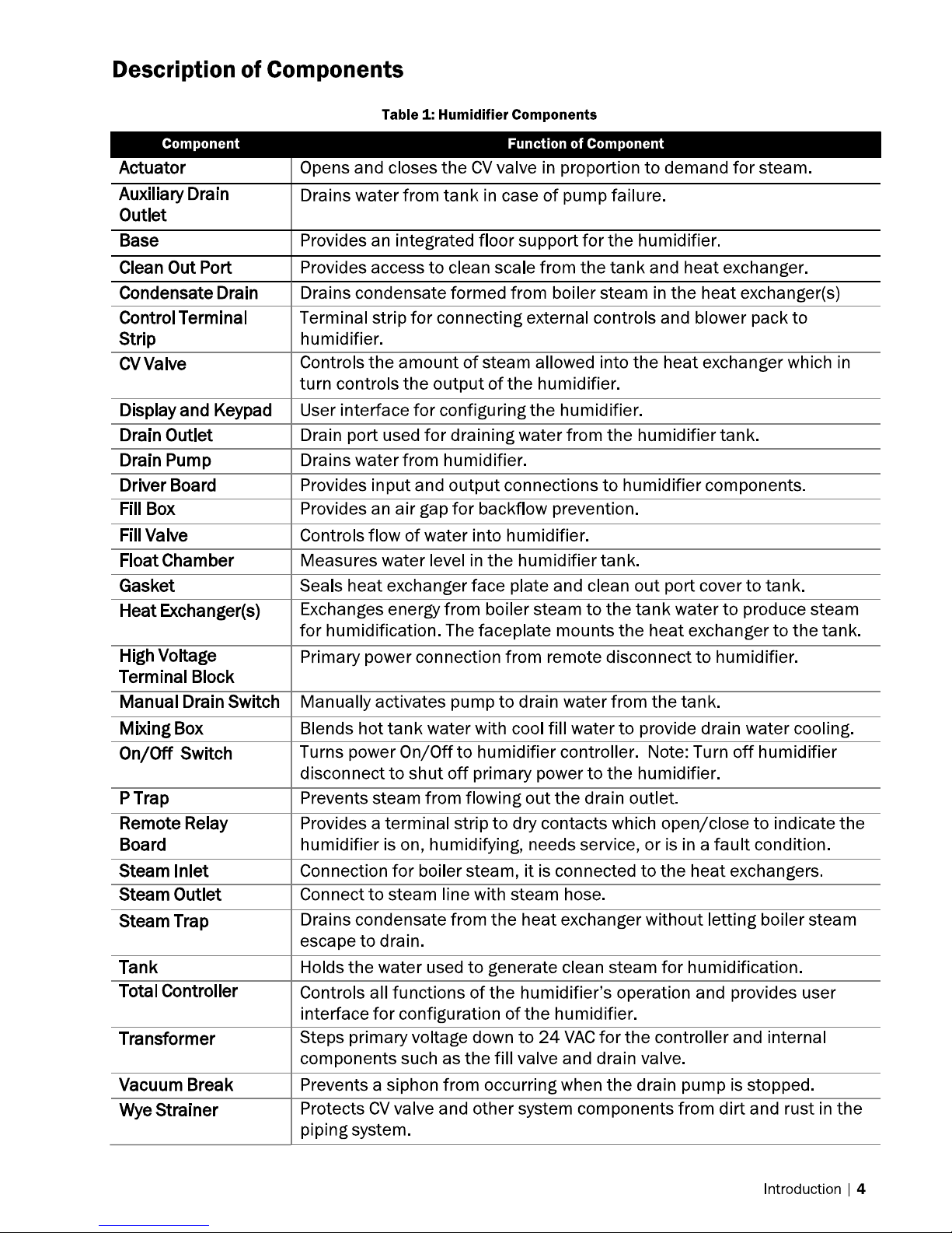
Page 5
Page 6
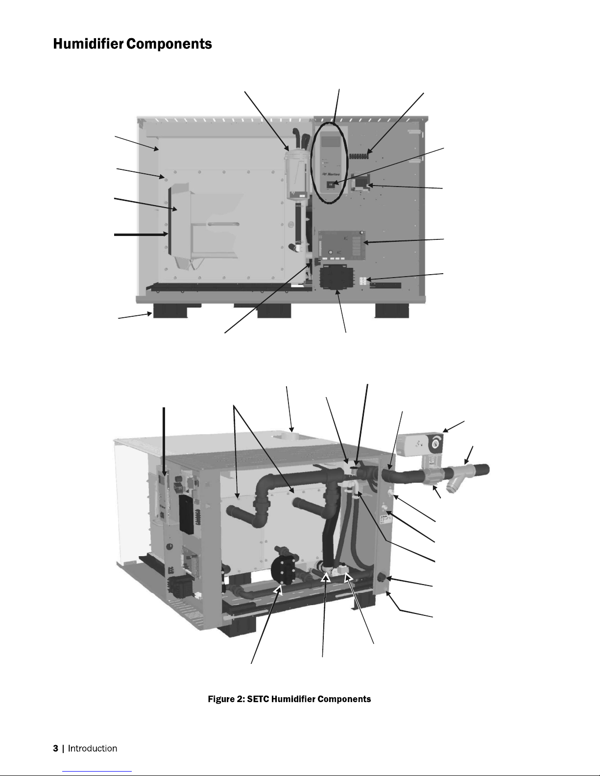
Tank
Clean Out
Port
Heat
Exchanger
Gasket
Base
Total Controller
Float Chamber
Manual Drain Switch
Heat
Exchangers
(Faceplate)
Display and Keypad
Steam Outlet
Transformer
Fill Box
Vacuum Break
Steam Inlet
(Boiler Steam)
Control Terminal Strip
On/Off Switch
Remote Relay
Board
Driver Board
High Voltage
Terminal Block
Actuator
Wye Strainer
Steam Trap
Drain Pump
Mixing Box
CV Valve
Fill Valve
Drain Outlet
P Trap
Condensate Drain
(Boiler Steam)
Auxiliary Drain
Outlet
Page 7
Page 8
SETC50
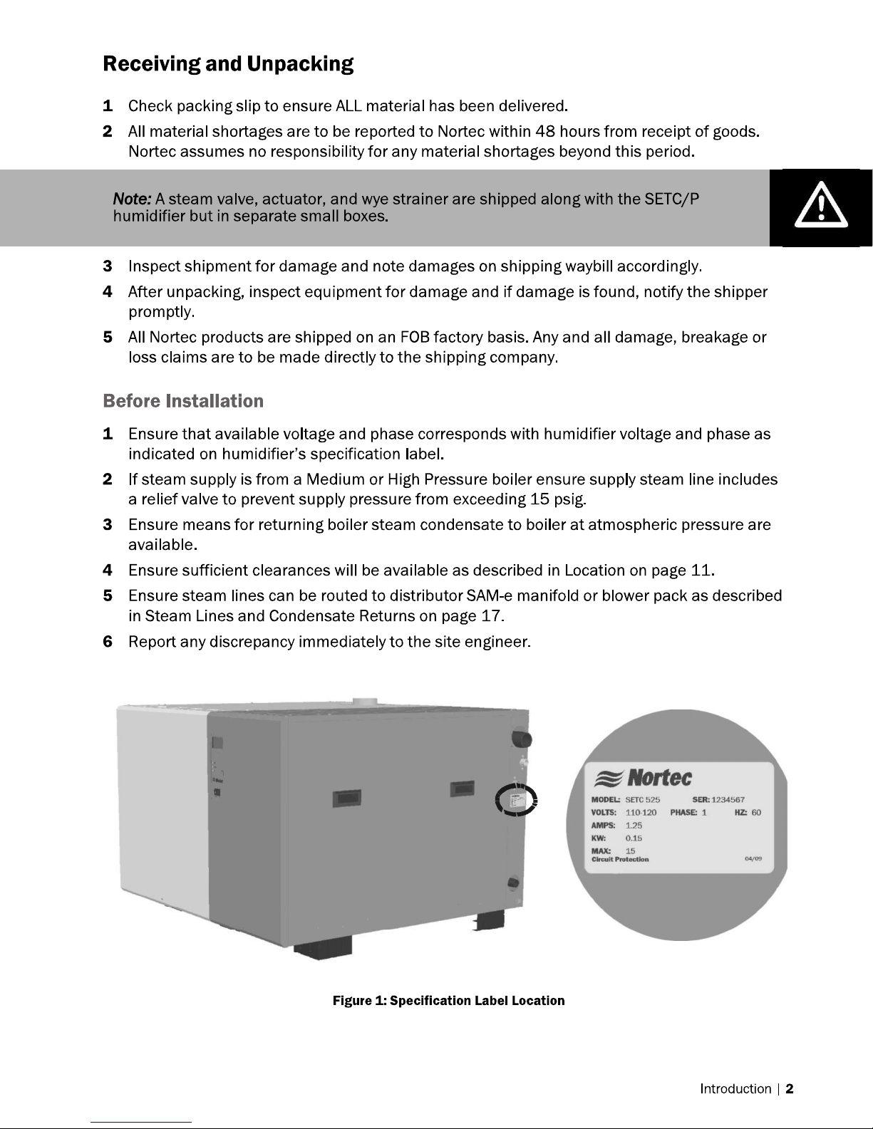
Note:
SE 750 has
outlets
SE 525
-
750
SE
100
-
175
SE
1050
SE 250
-
375
2 steam
Page 9
Page 10
Page 11

Page 12
Page 13

E
Ground
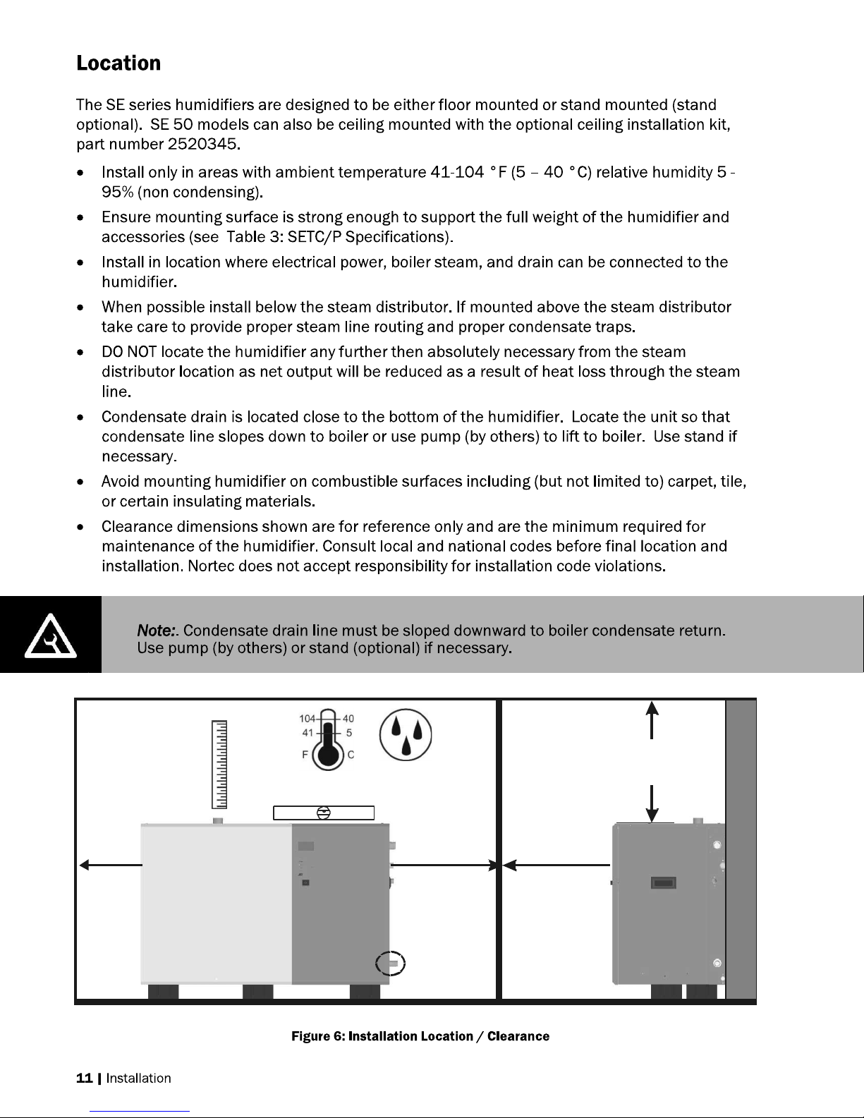
Location
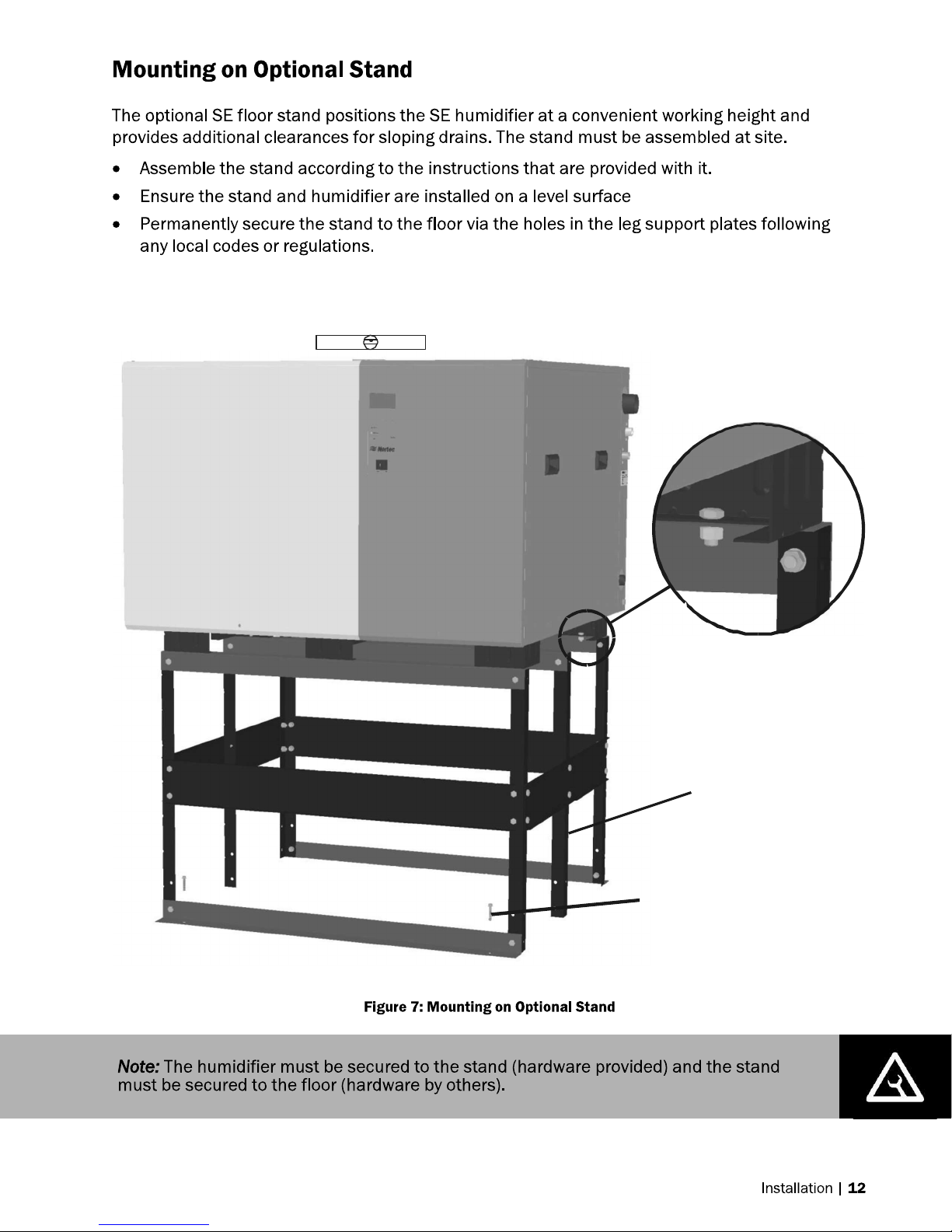
Mounting
Pg 11
Steam
Distribution
Pg 17
1 ft (30 cm)
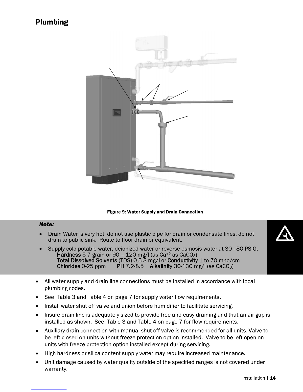
Plumbing
Pg 14
Boiler
Steam
Pg 15
Controls
Pg 23
Electrical
Pg 22
Modulation
Controls
2 in.
(5 cm)
min.
1ft (30 cm)
min.
On/Off
Controls
30 in.
(76 cm)
Min.
SE 1050
SAM-e Distribution Manifold
36 in. (91 cm)
Min. Top Clearance
(0 in SE 50)
30 in.
(76 cm)
Clearance
Min.
Side
30 in.
(76 cm)
Min.
Front
Clearance
Pressurized
steam supply
Water supply
30-80 psig
Tank drain
Air gap
Condensate
return to boiler
123- Ctrl Ground
45-
78-
9- Ground
10-
11-
12-
S
E
X T
T
C
/
P
24 VAC
On/Off Loop
Control Signal
Limit Signal
6-
5 VD C
Ground
Tank Blow Down
Actuator
Actuator
0-10 VDC Out
Dedicated
Circuit Breaker
or Disconnect
SETC/P
EXT
Page 14
As Close as
Possible to Steam
Distributor
Mount
Humidifier
evel
5-95%
36 in. (91 cm) Min.
Top Clearance
(0 in. for SE50 only)
30 in.
(76 cm)
Min.
SE 1050
only
30 in.
(76 cm)
Min. Side
Clearance
Condensate drain
line must be
sloped down, do
not use to lift
condensate
30 in.
(76 cm)
Min. Front
Clearance
Page 15
Fasten
SE
humidifier
nuts
Nm).
Note:
Center
support
only
and larger.
Secure
stand
to
floor
(hardware
by
others)
Mount stand on level surface
Ensure humidifier is Level
lock washers, and
to 200 in-lb (22.6
four places.
to stand with bolts,
provided. Tighten
present on SE 525
Page 16

Anchor 3/8 in (M10)
support rods to ceiling
(by others)
12.8 in.
(32.6 cm)
Sloped drain
1/2 in. pipe
(by others)
Support rods and hardware
(by others) must not extend
below support bracket flange.
Page 17
0.75 in. (19 mm). OD
un-threaded drain outlet
Connect with hose cuff
and hose clamps.
1/2 in. NPT
Use union to connect
supply pipe to unit.
Always install a water
shut-off valve.
Air gap required.
2 1/2 in. to 1 1/4 in. copper
reducer is ideal.
Hose/line must not touch
the bottom of the funnel.
Min. 1 1/4 in. OD drain line.
Slope down. Increase size
if combining multiple drains.
Axillary drain, 1/2 in. female NPT
For draining tank without pump. Leave
valve closed except if freeze protection is installed.
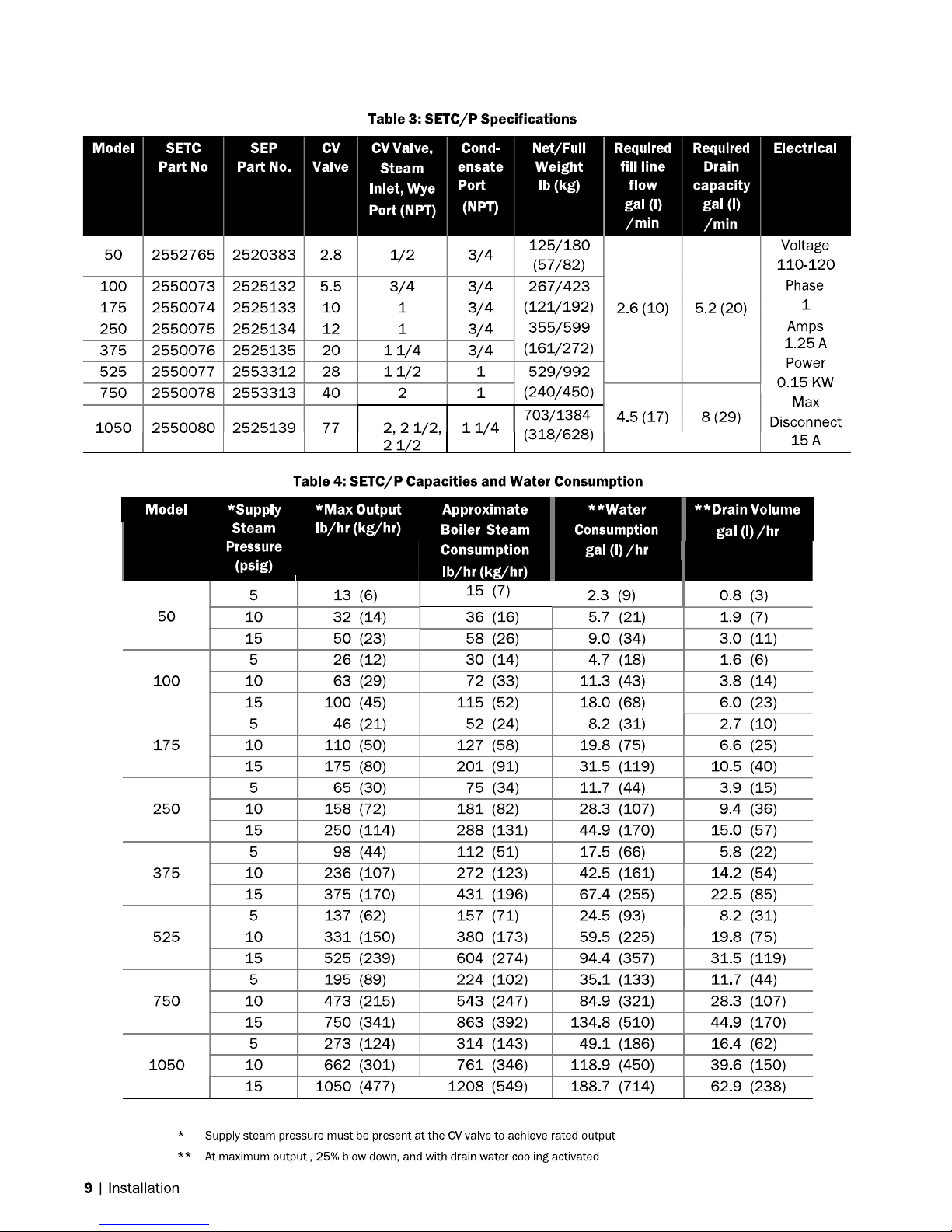
*Pipe, unions, and water shut-off valve not supplied by NORTEC.
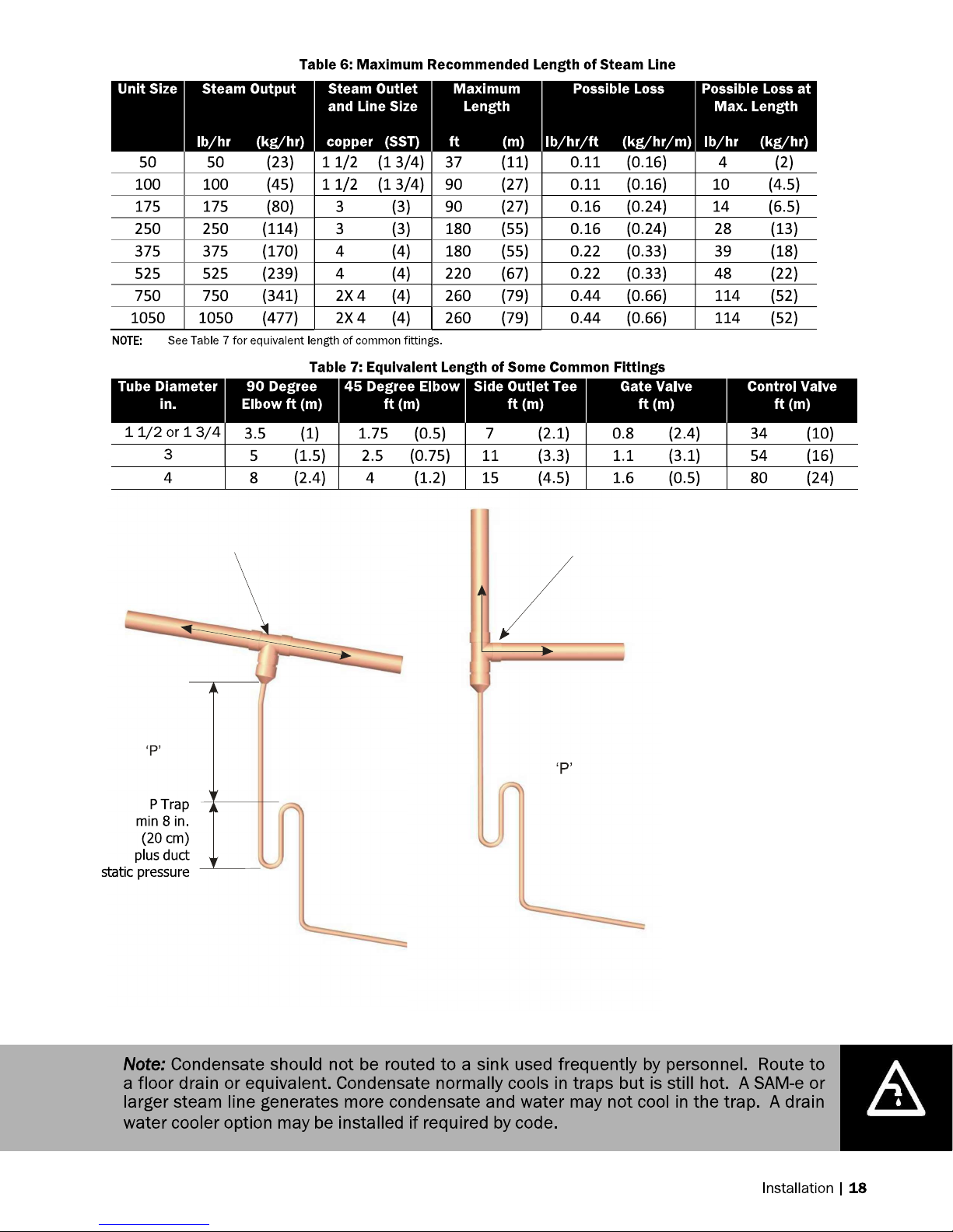
Page 18
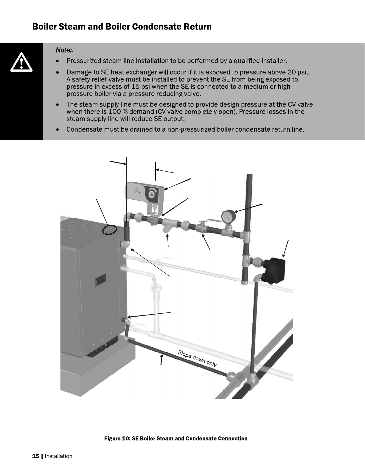
6 in.
cm)
Boiler
steam
supply
psi
measured
at CV
Valve
Actuator
(optional)
F&T Trap
Wye Strainer
Isolation
Valve
Boiler
steam
(see table 3)
Condensate
Drain
Condensate
drain
line.
must be lifted.
Boiler steam
inlet port location
on SE 1050
(15
Max
CV Valve
(see table 3)
inlet port
Port (see table 3)
line. Max 15 psi, Min 5
Pressure
gauge
Note: Nortec supplies CV valve, actuator
and wye strainer. All other
components and fittings by others.
Gravity feed to boiler.
Use pump if condensate
condensate header
Not pressurized
(slope down)
Pressurized condensate
header
Page 19
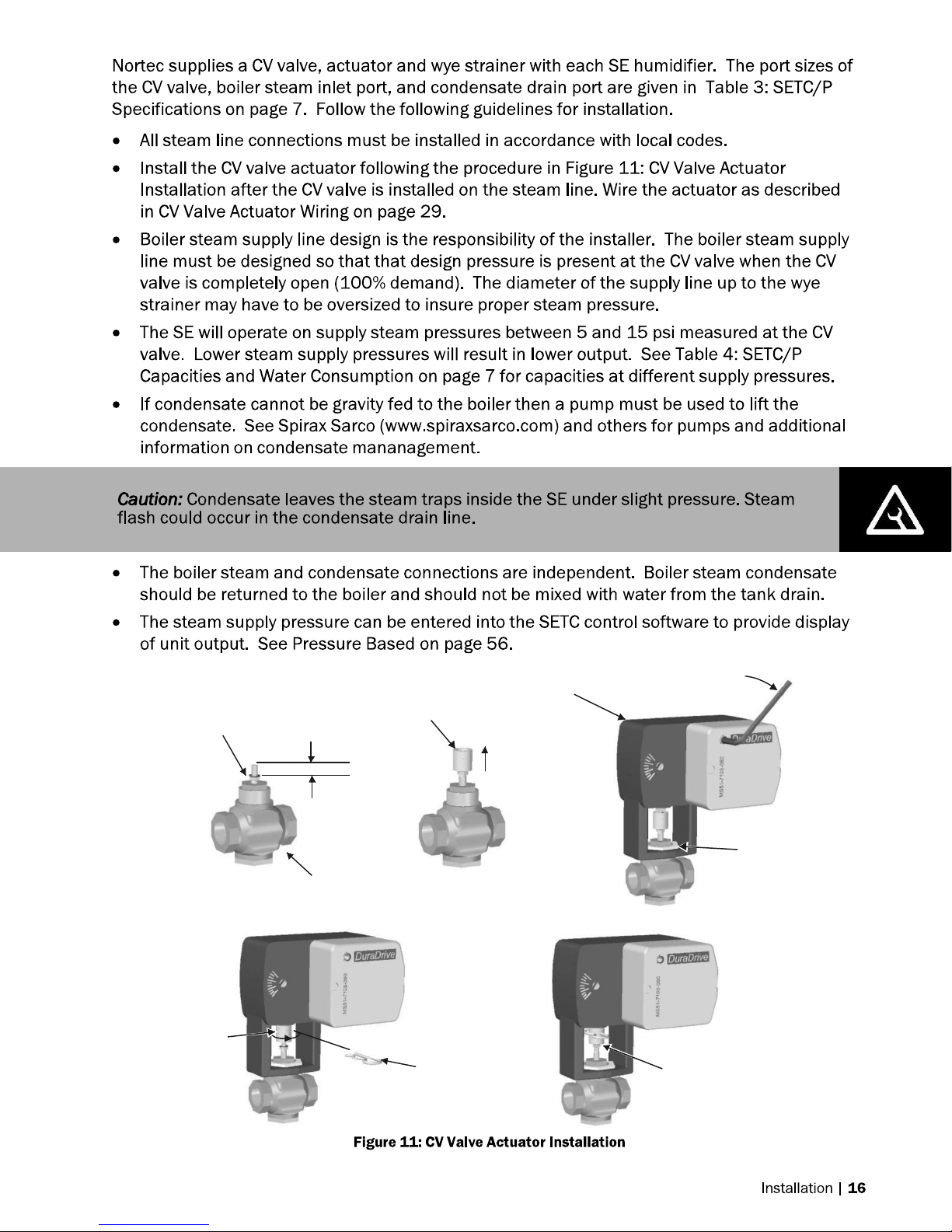
Install jam nut
and lock washer
Turn stem
extension
until holes
line up
1/2 in. (1.2 cm)
CV Valve
Install stem
extension
min.
Insert
connecting
pin
Actuator
Raise valve
stem to full up
2 turns then
push in and
1/8 turn to lock
Tighten jam nut
against stem extension
Install and
tighten
mounting nut
Page 20
10 Degrees
2 in.
) 1 ft
(30 cm)
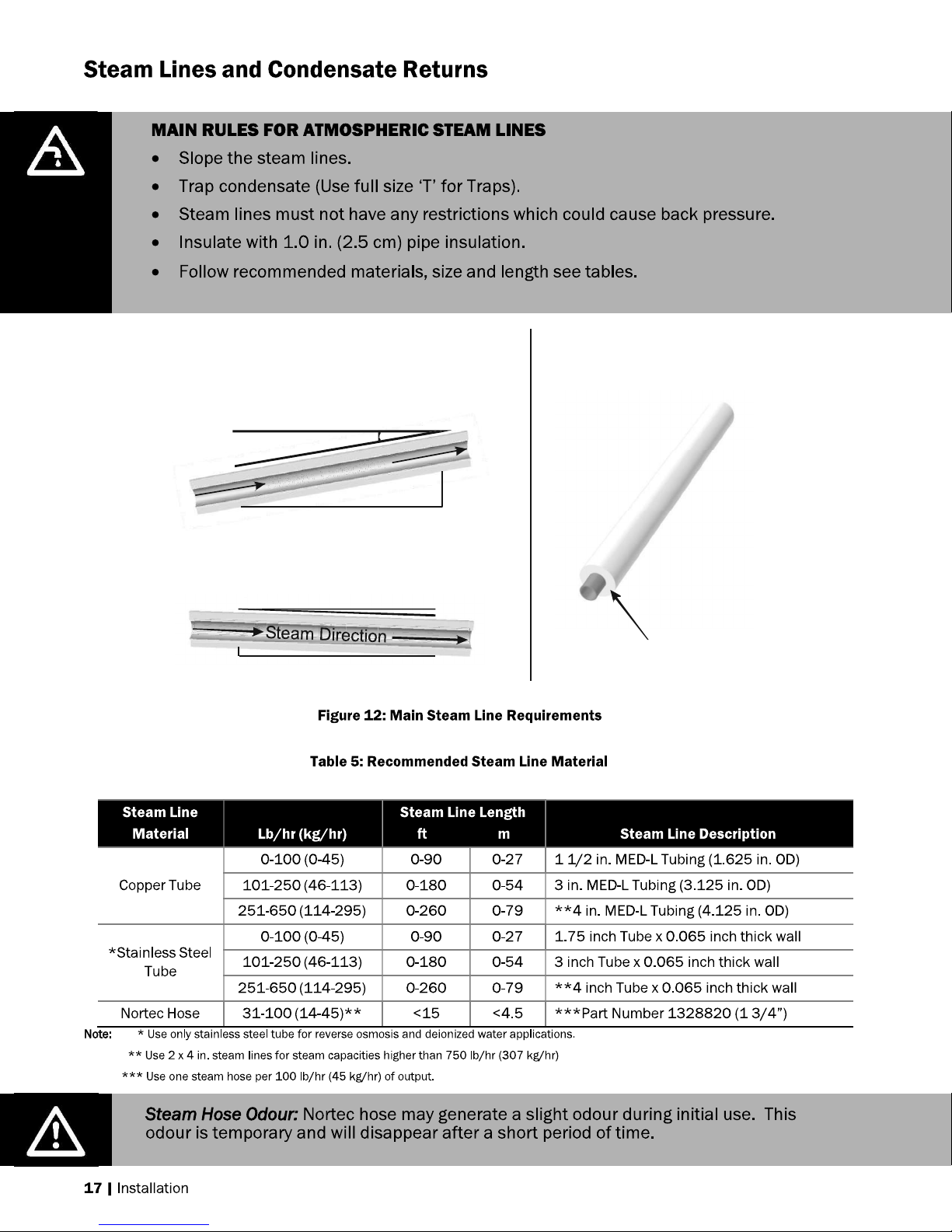
Use Appropriate Slope Insulate Pipe
(5 cm
0.5 in.
(12 mm)
St
eam
Dire
ction
1ft (30 cm)
2 Degrees
1 in. (2.5 cm) pipe
insulation
Page 21
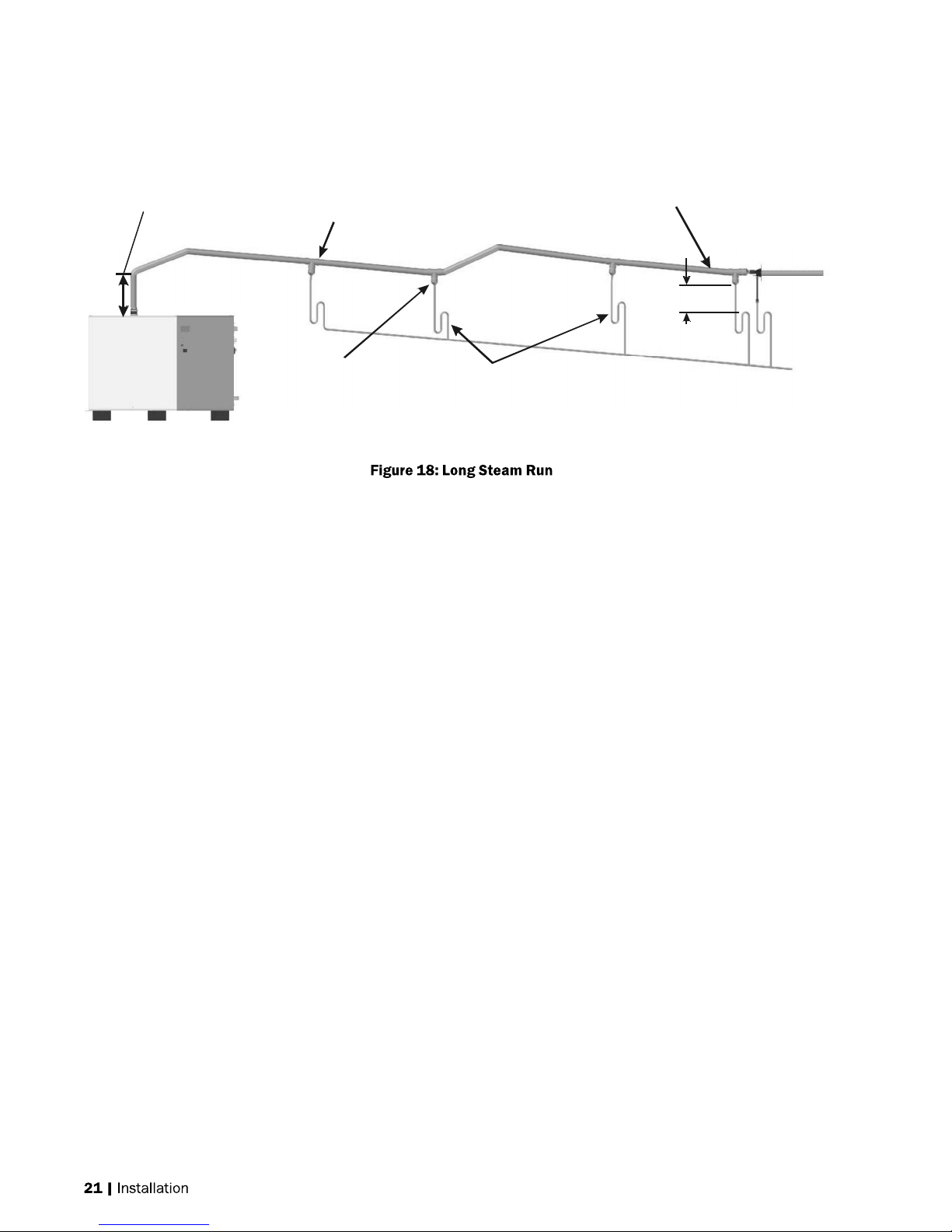
as steam
line
12 in. (30 cm)
min drop to
top of Trap
Tee is same size
Use a full size tee, not a 90
degree elbow for vertical
to horizontal transitions.
Traps Use:
-
NORTEC 0.375 in condensate hose .
-
1/4 in Med-L copper tubing, or
-
0.375 in stainless steel tubing
Condensate drains must be sloped down.
Route to humidifier fill cup if possible.
Page 22
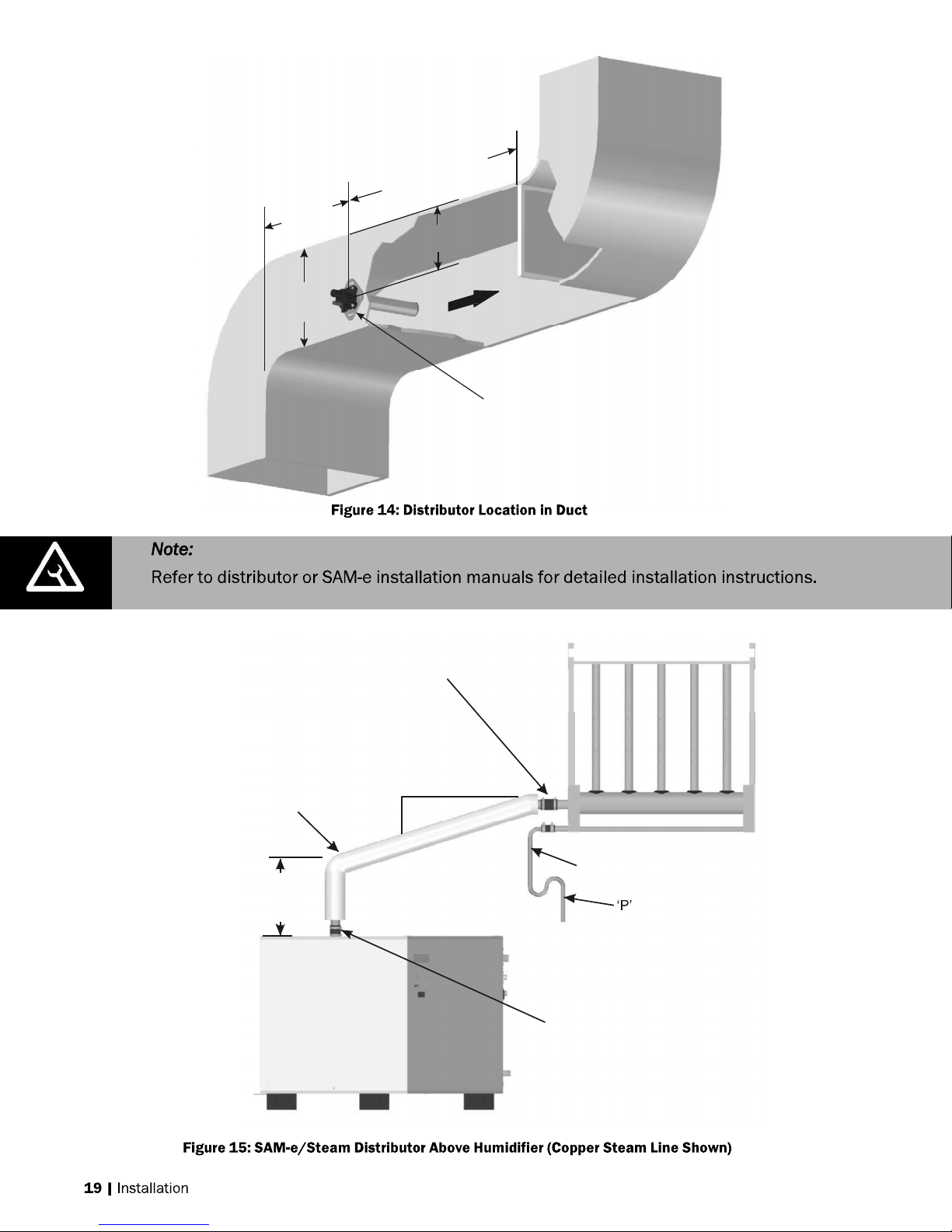
Calculated absorption
obstruction
if unknown
2 x duct
height min.
2/3 Duct
12 in.
(30
cm)
min.
Mount
distributor
to side of duct
distance to any
or 8-10 ft (2.4 - 3 m)
height
Insulated copper
steam line. Support
so weight is not on
steam outlet.
1 ft (30 cm)
min. before
anybend
2 in. (5 cm)
Hose cuff
with clamps
1 ft (30 cm)
min.
Condensate line
Trap
To drain
Use steam hose between
steam outlet and steam line.
Page 23

Min 12 in.
1 ft (30 cm)
0.5
in. (1.2 cm)
min.
1ft (30 cm)
re
Obstruction
1 ft (30 cm)
Use full s
ize condensate
tee
to
and immediately
after it.
Trap To drain
Trap To drain
(30 cm)
radius
Hose will soften
over time
proper support
Is necessary
1 ft (30 cm)
min. Before
any bend
Support Brackets
Install Condensate Tee
Before Distributor
Trap
1 ft (30 cm)
min.
Trap
To drain
To drain
min. befo
any bend
at low point. Slope lines up
min.
Page 24
Method for Longer Runs With Limited Vertical Space
1 ft (30 cm)
min before turn
Condensate
tee every
15-20 ft
(4.5 - 6 m)
Install condensate tee
before distributor
Condensate
tee at low
points
Individually trap multiple condensate
returns before joining on common line.
1 ft (30 cm)
min.
To Drain
Page 25
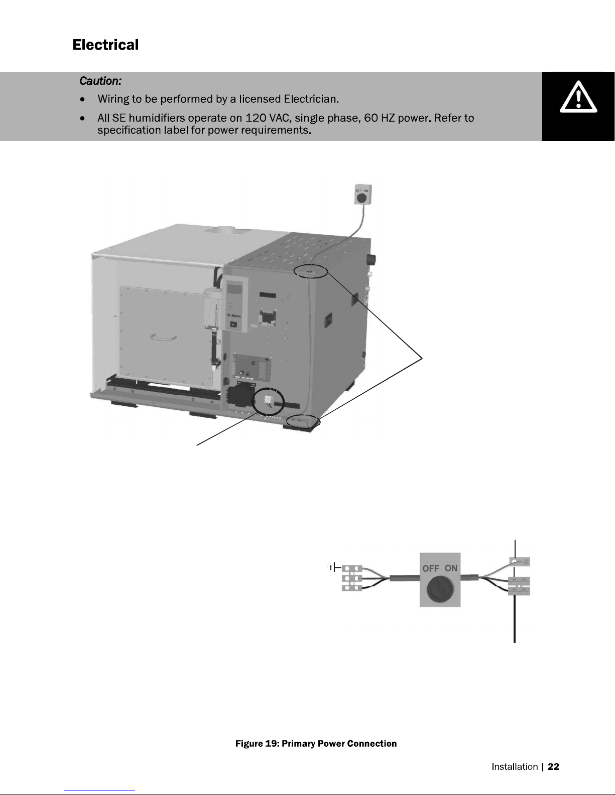
Knockouts provided
in top and bottom panels.
Install strain relief (by others)
High voltage
terminal block
Note:
1 Dedicated external fused
disconnect must be installed.
Fusing must not exceed max
circuit protection as indicated
on the specification label.
2 Ensure that adequate power is
available to carry full humidifier
amp draw as indicated on the
specification label.
3 All wiring to be in accordance
with national and local electrical
codes.
Single Phase Supply
Ground
L1
Neutral
SETC / P Primary Power
Dedicated circuit
breaker or fused
disconect.
E I
X N
Ground
L1
Neutral
T T
Page 26
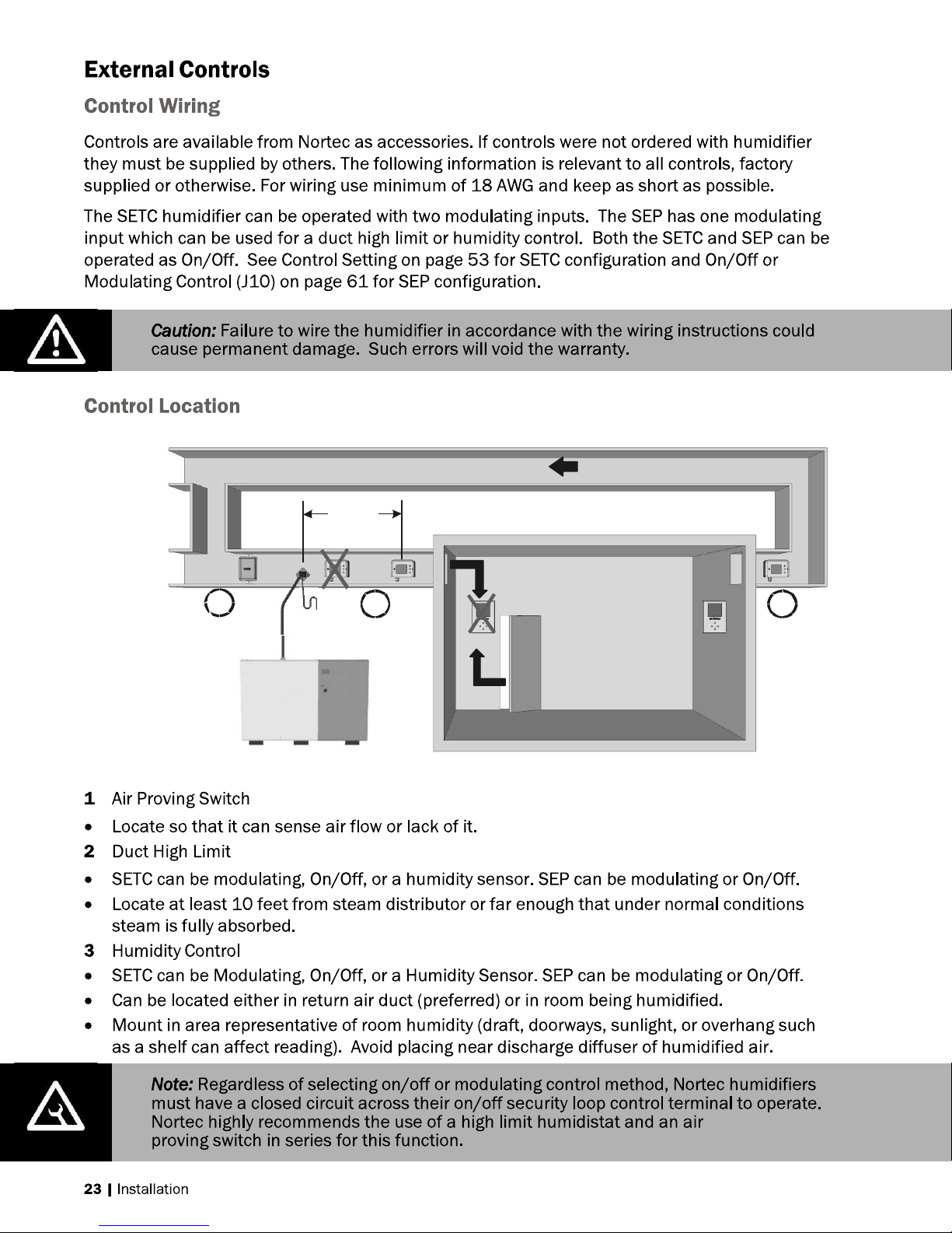
10 ft min.
1
Air
Proving
Switch
2
Duct High
Limit
3
Humidity
Control
(return air
duct or
in room)
Page 27
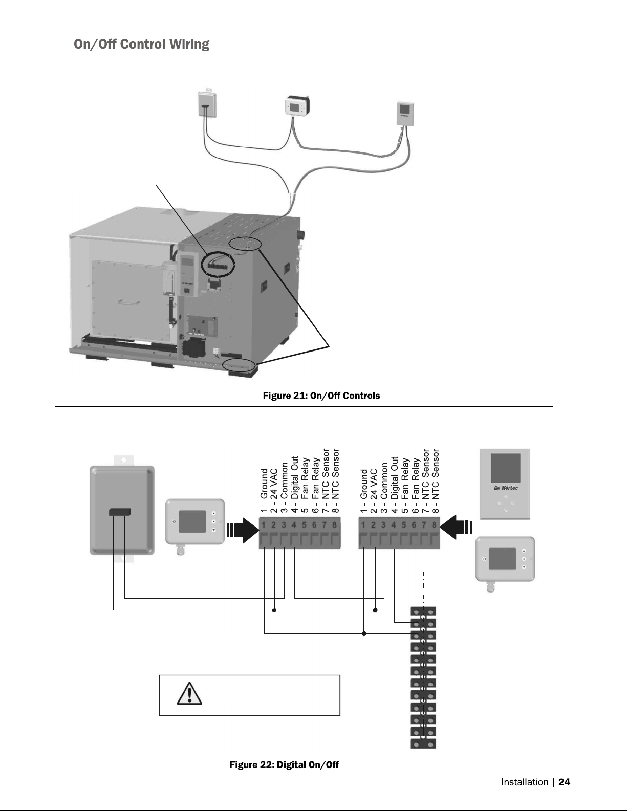
Air Proving
Com
Humidifier Terminal Strip
Switch
Duct High Limit
2548732 -On/Off
Duct Humidistat
Humidity Control
2548731 - On/Off
Wall Humidistat
Air Proving Switch
Wire to make when
sensing air flow
N/O
Knockouts provided
in top and bottom panels.
Install strain relief (by others)
Duct High Limit
2548732 - On/Off Duct Humidistat
Wire to make on drop in humidity
Note: 1 Humidifier will run when circuit between
terminal 1 and 2 on humidifier is closed.
2
Terminal 1 is 24VAC Hot, turn unit off to
avoid shorting while wiring.
3
Digital Humidistats require 24 VAC power
from terminals 1 and 3 of humidifier.
4
Humidity Control can be wall mounted
as shown or return air duct mounted.
Humidity Control
2548731 - On/Off Wall Humidistat or,
2548732 - On/Off Duct Humidistat
Connect 24 VAC ,
term inal 1 of hum id ifie r to
term inal 2 of co n t rollers.
OR
E S
X E
T
1- 24 VAC
2 - On/Off Loop
3 - Ground
4 - Control Signal
5 - Limit Signal (SETC only)
6 - 5 VDC
7 - Grou nd
8 - Full Tank Blow Down
9 - Ground
10 - Actuator power
11 - Actuator power
12 - 0-10 VDC Out
Page 28

Air Proving
1
-
Ground
1 -
G
r
ou
n
d
Switch
High Limit Humidistat
Control Humidistat
Humidifier Terminal Strip
Note: 1
Install On/Off controls or jumper between
terminal 1 and 2 of humidifier in order to run.
2
Terminal 1 is 24 VAC Hot, turn unit off to
avoid shorting while wiring.
3
High Limit Humidistat must be duct mounted.
It can be On/Off or modulating.
4
Control Humidistat can be mounted in space
or in return air duct and can be On/Off or
modulating.
5
The SEP can only accept one modulating
signal.
Knockouts provided
in top and bottom panels.
Install strain relief (by others)
2520266 - Digital Duct Humidistat
Analog Out - 3
24 VAC - 2
Ground - 1
Package
2 - 24 VAC
6 - Analog Out
7 - Analog In
8 - Temperature
Connect 24 VAC, terminal
1 of SETC/P to terminal
2 of controllers.
1510142 - Digital Wall Humidistat
2 - 24 VAC
6 - Analog Out
8 - Temperature
Insert On/Off
controls or jumper
between 1 and 2
1- 24 VAC
2 - On/Off Loop
3 - Ground
4 - Control Signal
5 - Limit Signal (SETC only)
6 - 5 VDC
7 - Ground
8 - Full Tank Blow Down
9 - Ground
10 - Actuator power
11 - Actuator power
12 - 0-10 VDC Out
E
S
X
E
T
Page 29
1
-
Ground
Temperature
1
-
Ground
Out
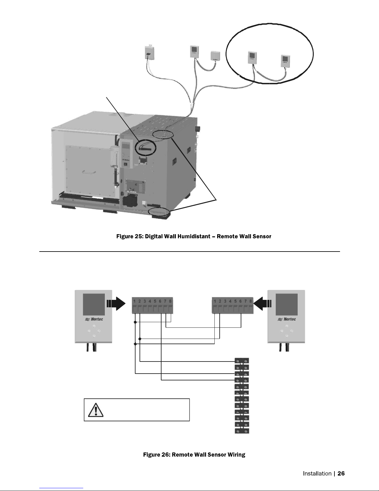
Air Proving
only)
Switch
Duct High
Limit
2520261 - Digital
WallW/O Sensor
1509858 - Wall
Sensor
Humidifier Terminal Strip
2520261 - Digital
Wall W/O Sensor
Connect 24 VAC, terminal
1 of SETC/P to terminal
2 - 24 VAC
6 - Analog Out
2 of controllers.
2520261 - Digital Wall W/O Sensor
+
1509858 - Wall Sensor
Wire wall sensor to digital display as shown
below, wire digital display to humidifier as shown
for 151014 2 - Digital Wall Humidistat.
Knockouts provided
in top and bottom panels.
Install strain relief (by others)
7 - Analog In
8 -
2 - 24 VAC
6 - Analog
1509858 - Wall
Sensor
1- 24 VAC
2 - On/Off Loop
3 - Ground
4
- Control Signal
5
- Limit Signal (SETC
6
- 5 VDC
7
- Ground
8
- Full Tank Blow Down
9 - Ground
10 - Actuator power
11 - Actuator power
12 - 0-10 VDC Out
Page 30
1
- Ground
Out
Air Proving
1
-
Ground
Out
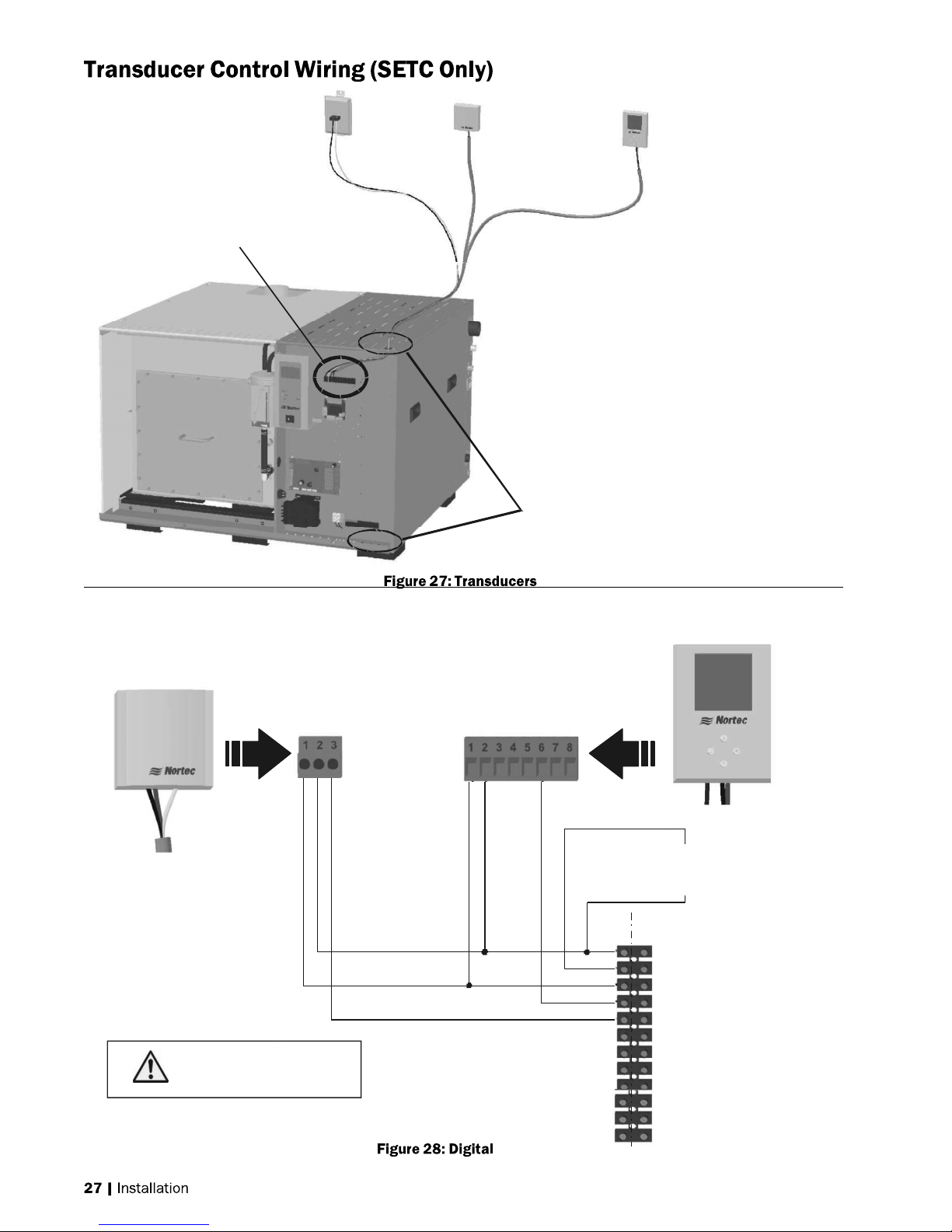
E
Switch
Duct High Limit
1509857 - 2-10V
Duct Humidity
Transducer
Humidity Control
1509858 - 2-10V Wall
Humidity Transducer
Humidifier Terminal Strip
1509857 - 2-10V Duct Humidity
Transducer
Note: 1
Install On/Off controls or jumper between
terminal 1 and 2 of humidifier .
2
Terminal 1 is 24 VAC Hot, turn unit off to
avoid shorting while wiring.
3
Duct High limit can be duct humidity
transducer as shown or duct On/Off
humidistat.
4
Humidity Control can be wall humidity
transducer as shown, duct humidity
transducer, or On/Off humidistat.
Knockouts provided
in top and bottom panels.
Install strain relief (by others)
1509858 - 2-10V Wall Humidity
Transducer
2 - 24 VAC
Co n n ect 24 VAC ,
term inal 1 of SETC to
term inal 2 of con tro llers
3 - Analog
2 - 24 VAC
6 - Analog
Insert On/Off
controls or jumper
between 1 and 2
E
S
X
T
1- 24 VAC
2 - On/Off Loop
3 - Ground
4
- Control Signal
5
- Limit Signal (SETC only)
6 - 5 VDC
7
- Ground
8
- Full Tank Blow Down
9 - Ground
10 - Actuator power
11 - Actuator power
12 - 0-10 VDC Out
Page 31

1
-
Ground
Sensor
Sensor
1
-
24
VAC
2548731 - On/Off Wall Humidistat or,
2548732 - On/Off Duct Humidistat
OR
Note:
1 The Temperature sensor is
intended for duct mounting.
2 Locate the temperature sensor
near the fresh air intake. This
will ensure accurate representation
of the outdoor air temperature.
Connect 24 VAC, terminal
1 of humidifier to terminal
2 of controllers.
2 - 24 VAC
3 - Common
4 - Digital Out
2520263 - Outdoor Temperature
5 - Fan Relay
6 - Fan Relay
7 - NTC
8 - NTC
Insert Other
On/Off
controls
in series
2 - Temperature
Sensor
E S
X
T
E
1- 24 VAC
2 - On/Off Loop
3 - Ground
4 - Control Signal
5 - Limit Signal (SETC only)
6 - 5 VDC
7 - Ground
8 - Full Tank Blow Down
9 - Ground
10 - Actuator power
11 - Actuator power
12 - 0-10 VDC Out
Page 32

2520263 - Outdoor Temperature
1
- 24
VAC
Ground
Out
Sensor
Note:
1
The Temperature sensor is
intended for duct mounting.
2
Loc ate the tem perature sensor
near the fresh air intake. This
will ensure accurate representation
of the outdoor air temperat ure.
Connect 24 VAC, terminal
1 of SE to terminal
2 of controllers.
1510142 - Digital Wall Humidistat or,
2520266 - Digital Duct Humidistat Package
2 - Temperature
1 -
2 - 24 VAC
6 - Analog
8 - Temperature
Insert On/Off
controls or jumper
bet ween 1 and 2
E S
X E
T
1- 24 VAC
2 - On/Off Loop
3 - Ground
4
- Control Signal
5
- Limit Signal (SETC only)
6 - 5 VDC
7
- Ground
8
- Full Tank Blow Down
9 - Ground
10 - Actuator power
11 - Actuator power
12 - 0-10 VDC Out
SE 50 - 750
Actuator
Note: 1 Wire the CV valve actuator
to the low voltage
terminal strip.
2 Use minimum of 18 AWG wire
and keep as short as possible.
3 After installation and powering
humidifier verify that travel of
actuator at full de mand is to the
fully open position.
Actuator
SE 10 50
SE 1050 low
volta ge terminal strip
Bk
R
Gr
Y/Bk
SE 50 - 750 Terminal Strip
9 - Gro u nd
R
Bk
Y/Bk
10 - Actuator 24 VAC
11 - Actuator Gr ound
12 - 0-10 VDC Out
9 - Gro u nd
10 - Actuator 24 VAC
11 - Actuator Gr ound
12 - 0-10 VDC Out
Page 33

Page 34

Daisy
Chain
up to 16
Slave
1
Slave
X
Master
Daisy
chain
pole 2 and 3
driver
board.
Humidifiers
of terminal
Note:
Do not reverse polarity.
Do not connect to pole 1 or 4.
J2a-RS485
of the
Page 35

Page 36

Page 37

2 x duct height
from fan or
On/Off Controls
(Air Proving)
in series between
terminal 1 and 2
Steam Line
- Adequate slope
- No restrictions
- No kinks (hose)
- Condensate traps
on long runs
Mounting
- Unit level
- Service clearance
- Properly anchored
if on stand
transition
Disconnect
Correct voltage,
amps, phase
Calculated absorption distance
to any obstruction or 8 - 10 ft
(2.4 - 3 m) if unknown.
P Trap(s) with 12 in .
(30 cm) min. drop(s)
.
Actuator,
- Opens CV Valve
fully at 100%
demand
- Closes fully at 0%.
Air gap
Spec label
Boiler Condensate
- Gravity fed to boiler
or lift pump
Min 10 ft (3 m)
Boiler Steam
- Max 15 psi
- Safety valve if from
med. or high press.
boiler.
- Design pressure
at 100% demand.
1/2 in line min
30-80 PSI
Not plastic drain,
Not to sink.
High Limit
- Wired to terminal 5
- On/Off in series
between terminal
1 and 2
Control
- Wired to terminal 4.
- On/Off in series
between terminal
1 and 2.
- In return duct or
location which
represents humidified
space (no drafts,
not by door, not
by diffuser).
Page 38

LCD Display and
Manual
Input Buttons
(Buttons used to navigate .
status screens and
configure the humidifier,
correspond to icons on
the display)
Status LEDs
Software Drain Button
(Initiates a software
controlled drain)
On/Off Switch
(Turns humidifier On/Off)
drain
switch
Page 39

Menu
Request
xx%
Idle 0 lb/hr
04/30/09
14:25:22
Security loop: Closed
Page 40

Menu
Request
100%
Idle
04/30/09
loop:
750 lb/hr
Menu
Request
xx%
Idle
loop:
0 lb/hr
Menu
CONTROL
: 100%
lb/hr
CONTROL
Pt
: 100%
lb/hr
Menu
HUMIDIFIER
: SETC
750
StandAlone
Security
14:25:22
Closed
04/30/09
Security
Man Cap.
Demand
Limit
Output
14:25:22
Closed
Man Cap.
: 55%
: 80%
: 0
RH CNT
CNT Set-
RH Limit
LIM Set-Pt
Output
Menu
: 55%
: 50%
: 100%
: 70%
: 0
Model
Capacity
Multimode
REG Mode
Software
Press. In
: 750 lb/hr
:
: Demand
: XVXX
: 15 psi
Page 41

Menu
Analog
Output
Output
Signal
:
X.X
VDC
Menu
100%
0%
-4
hrs 0 hrs
Demand:
45%
Menu
Menu
Menu
Menu
Capacity
Total O/P
Tank Monitor
Quick Warm
Press. Base
: xxx lb/hr
: xxx lb/hr
: On/Off
: On/Off
: On/Off
TANK STATUS
Fill Valve : ON/OFF
Drain Pump : ON/OFF
Float Level 5
Run Time : xxx hr
Serv. Time : xxx hr
Serv Due : xxx hr
SENSOR INPUTS
Sec. Loop : Closed
Tank Temp. : Closed
FEATURES LIST
Idle Mode : Idle Drain
FTBD : On/Off
Time Prop. : On/Off
BD Rate : 25%
Drain Cool :On/Off/Smart
Float Check : On/Off
FEATURES LIST
Idle Mode : Idle Drain
FTBD : On/Off
Time Prop. : On/Off
BD Rate : 25%
Drain Cool :On/Off/Smart
Float Check : On/Off
Page 42

Humidity (RH %)
Indicates the
humidistat is on.
A half moon
indicates it is off.
Snowflake indicates the
setpoint is being
overridden by outdoor
temperature.
Power button turns
off the humidiistat if
pressed for 2 seconds
Output signal is shown on
modulating controller
proportional to the demand.
State of On/Off humidistat
Setpoint (RH%)
Option button accesses
sensor calibration.
See troubleshooting
Increase / Decrease Setpoint
Page 43

Humidity (RH %)
Option button accesses
sensor calibration.
See troubleshooting
Adjust calibration
while in calibration
mode
Power button will
display if an
attempt is made to
turn off the transducer.
Page 44

Page 45

If no, perform Pre-Start-up Checklist before starting humidifier.
The prerequisites for the humidifier activating the CV valve actuator to make steam are as follows:
The Humidifier will undergo a self-test when the power is turned on activating the and other
internal components followed by a float test.
If the above listed prerequisites are fulfilled the humidifier will fill the tank, open the CV valve and
begin normal operation.
Page 46

Page 47

Fault LED On
Indicates the controller has detected a
fault condition and stopped humidifier.
Check display for fault information
Service LED On
Indicates that service may be required
or that a warning condition exists.
Check display for warning information
Service LED Blinking
Indicates drain button has been pushed
and unit is draining.
ON LED On
Indicates steam is being produced.
ON LED Blinking
Indicates demand with safety loop open.
DEMAND LED On
Indicates steam is being produced.
DEMAND LED Blinking
Indicates humidifier is in standby waiting
for a demand.
SERVICE LED Flashing
Indicates the controller has detected a
fault. The flash sequence of the LED
indicates which fault has been detected.
FAULT LED On
Indicates the controller has detected a
fault condition and stopped humidifier.
Read Service flash sequence to
determine fault detected.
DEMAND
SERVICE
FAULT
ON
OFF
DRAIN
Page 48

Heat Exchanger
Steam
Line Steam
Distributor
CV
Valve
Actuator
Trap Tank
Float Chamber
Fill Box Cooling
to
Valve
Boiler
Steam
Valve
Vacuum
Break
Steam
Trap
Trap /
Condensate
Boiler
Auxiliary
Drain
Lower
Mixing
Drain
Pump
Float Chamber
Dual Fill
CV
Return to
Drain
Outlet
Overflow
Box
Page 49

Page 50

Insulated copper
steam line. Support
so weight is not on
steam outlet.
SAMe Manifold
Condensate line
Trap
Page 51

Insulate
steam lines
Blower Pack Blower Pack
Balance steam
line length to all
blower packs
Blower pack
condensate dain
and Trap
Provide 120 V
disconect for
blower packs
power.
Wire blwoer pack safety loop
terminals in series with humidifier
safety loop.
Condensate
to drain
Oversize condensate
line to combine multiple
condensate returns
Page 52

5
Screen Displays
Press
to go
down
a
go left information
up a menu
increase/
accept
menu
level
/right one about
current
setting
and
screen
warning
or fault
value
go up a
Request
100%
Idle
: 150 lb/hr
Menu ?
?
Menu
Menu Set
Menu
Set
Request
100%
Password
Idle 30 lb/hr
Set
Screen
Displays
ESC S et
04/30/09
Security loop
14:25:22
Closed
Set P
45%
45%
45 %
Press to
04/30/09 14:25:22
Security loop:
Closed
?=Press for Press to go Press to
level decrease
message
0335
Enter Code
Confirm with
Press to
level
Main Menu
Service Level
Service Level
User Defined Settings
Control Settings
Diagnostics
Page 53

500 hr
Set No Yes Menu
Set No Yes Menu
Menu Menu Set
Service Level
Tank Drain
Reminder
Set
Service Reminder : 500
Service Reminder :500
Tank PreClean
Reset Error History
Reset Serv.
Tank Drain
Service Reminder
500 hr
500
Interrupt Operation
Tank PreClean
Reset Error History
Reset Serv. Reminder
Interrupt Operation?
(This Operation
Can Take >1 hr)
Reset Error History
Menu Yes No Set
Reset Serv. Reminder
No
Menu
Yes
Set
Page 54

Menu Set
Menu
Smart
User Defined Settings
BD Rate
Hours
: 25%
Drain
Set
100
Drain Cool : On
Drain Cool : Off
FTBD
FTBD Time
FTBD
Idle Mode
Idle Time
Fill Corr
Drain Corr
Float Ck
Date
Time
Unit
Language
Contrast
Leak Ck
: Off
: Off
: 100
: Idle
: 72 hr
: 100%
: 100%
: 23:30
: 06/27/09
: 13:22
: lb/hr
: English
: 10
: Off
BD Rate : 25%
Drain Cool
On
Off
On
On
Blowdown Rate
25%
FTBD : Off
FTBD Time : Off
Menu
Full Tank Blowdown
Off
On
On
Menu
FTBD Time
Hour 23
Hour 23
Menu
FTBD Hours
100
100
Set
Set
Set
FTBD Hours : 100f
Menu
Set
Page 55

Keep Warm
Idle Mode : Idle Drain
Menu Set
Menu Set
Menu Set
Idle Mode
Idle Drain
Idle Drain
Idle Drain
Idle Time : 72 hr
Fill Corr : 100%
Menu
Idle Time
72 hr
72 hr
72 hr
Menu
Fill Correction
100 %
100 %
100 %
Menu
Drain Correction
100%
Set
Set
Set
Drain Corr : 100%
Float Ck : 23:30
Date : 27/06/09
100 %
Float Ck
Hour 23
Hour 23
Minute 30
Date
Day 27
Day 27
Month 06
Page 56

10
Menu Set
Time : 13:22
Menu Set
lb/hr
Menu Set
Menu Set
Menu Set
On
Unit : lb/hr
Language : English
Time
Hour 13
Hour 13
Minute 22
Unit Steam
lb/hr
lb/hr
kg/hr
Language
English
English
English
French
Dutch
German
Contrast 10
Leak Ck : Off
Contrast
10
10
Leak Check
Off
Off
Off
Page 57

Menu Set
Control Setting
Short
CD : On
(PI)
Menu Set
Source
Analog
Menu Set
Demand
Menu Set
Menu Set
Source : Analog
Source : Analog
REG Mode : Demand
MOD Mode : Dual CH
Multi Mode : Standalone
CNT Type : 0-10
LIM Type : 0-10
Only present if Mod Mode set to Dual CH
Short CD Tm : 30 s
Time Prop. : Off
Manual Cap : 100%
Mulit Unit Op Range
Modbus Settings
Press Base : On
Supply Press. : 15 psi
RH Settings
REG Mode : Demand
Only present if Short CD set to On
Only present if Multimode set to Master or Slave
Only present if Press Base set to On
Only present if REG Mode set to RH (P) or RH
Analog
Analog
Digital
Regulation Mode
Demand
On/Off
RH (P)
RH (PI)
MOD Mode : Single CH
Multi Mode : Standalone
MOD Mode
Single CH
Single CH
Single CH
Multi Mode
StandAlone
Standalone
StandAlone
Slave
Page 58

Menu Set
CNT Type : 0-10
Menu Set
LIM Type : 0-10V
Short CD : Off
CNT Type
0-10 V
0-5 V
1-5 V
0-10 V
0-10V
2-10 V
0-16 V
32-16 V
0-20 mA
4-20 mA
LIM Type
0-10 V
0-5 V
0-10 V
0-10V
2-10 V
0-16 V
3.2-16 V
Menu
Set
Short Cycle Delay
Off
Off
Off
Short CD Tm : 30 s
Time Prop. : Off
Menu
Short Cycle Delay Time
30 s
30 s
Menu
Time Proportioning
Off
Off
Off
Menu
Manual Capacity
100%
Set
Set
Set
Manual Cap : 100%
100%
100%
Page 59

Menu Set
Menu
Set
Multi Unit Op. Range
Modbus Settings
Press. Based : On
Multi Unit Op. Range
Zero Out
Full Out
Full Out : 20%
: 20%
: 0%
Modbus Settings
Parity : Even
Parity : Even
Timeout : 300 s
Rem Disable : On
Pressure Based
On
Off
On
Menu
Set
Page 60

CNT Band : 15% RH
RH Alerts
: On
Menu Set
Supply Press. : 15 psi
Supply Pressure
15 psi
15 psi
15 psi
RH Settings
Menu
Set
RH Settings
CNT Set-P : 40% RH
CNT Set-P : 40%
CNT Itime : 5 min
LIM Set-P : 80% RH
LIM Band : 15% RH
LIM Damp : 5 s
RH High : 75% RH
RH Low : 33% RH
Only present if MOD Mode is set to Dual CH
Only present if RH Alerts is set to On
CNT Set-P : 40%
CNT Band : 15% RH
CNT Itime : 5 min
Control Set Point
40% RH
40% RH
40% RH
Menu
Control Band
15% RH
15% RH
Menu
Control Integral Time
5 min
5 min
Menu
Set
Set
Set
Page 61

Limit Set Point
On
80% RH
LIM Set-P : 80%
LIM Band : 15% RH
LIM Damp : 15% RH
80% RH
Menu
Limit Band
15% RH
15% RH
Menu
Limit Damping
5 s
5 s
Menu
RH Alerts
Set
Set
Set
RH Alerts : On
RH High : 75%
RH Low : 33% RH
On
On
Menu
RH High
75% RH
75% RH
Menu
RH Low
33% RH
33% RH
Menu
Set
Set
Set
Page 62

Menu Menu Set
Diagnostic Menu
Service
History
Fault History
Set
Menu Set
Menu
Set
Output
Test
Inlet Valve:
Remote
Test
Steam
Rel
ay:
Fault History
Fault History
Output Test
Remote Test
Service History
04.14.07 21:48 E19A
03.20.09 02:35 E19A
Service History
04.21.07 09:10
03.21.09 10:10
Output Test
Remote Test
Off
Off
Menu
Set
Page 63

Blowdown
Adjustment
Potentiometer
Jumpers
J11 to J18
25%
0% 50%
Jumper
J10
Page 64

Page 65

Page 66

Page 67

Service LED On
+
HMW - Humidifier
Maintenance
=
Service timer has
expired and humidifier
needs maintenance
+ 200 Hours
Fault LED On
HMF - Humidifier
Service timer + 200 hours
has passed. Maintenance
must be performed.
+
Maintenance
=
Humidifier has
shut down.
Request 68%
Warning
HMW - Humidifier Maintenance
Humidifying 134 lb/hr
04/30/09 14:25:22
Security loop: Closed
Menu
Request 68 %
Fault
HMF - Humidifier Maintenance
Fault 34 lb/hr
04/30/09 14:25:22
Security loop: Closed
Menu
?
?
Page 68

Page 69

Top Cover
Front Cover
Front Maintenance Door
Gaskets
Tank Door Locknuts.
Apply anti seize compound
to remove.
Do not crush gasket.
Max 5 ft-lbs torque.
Top Maintenance Door
(SE 525 - 1050 Only)
Page 70

F&T Trap
Union
Steam Connection Union
F&T Trap
F&T Trap
Union
Heat Exchanger
Heat Exchanger Gasket
Cabinet Cover
Heat Exchanger Locknuts
Apply anti seize compound
to remove.
Do not crush gasket.
Max. 5 in-lb torque
Page 71

Caution:
Do not
reverse
To tank To fill valve
Squeeze
tabs
assembly
humidifier
float chamber
hoses
to remove
from
Page 72

Page 73

Page 74

Page 75

Page 76

Page 77

Page 78

Page 79

Clock Fault
Drain Ck Fault
Controller
failure.
The drain pump
is activated but
water level has
not decreased
clock
Page 80

Fill Check Fault
The fill valve has
been active for
an extended
time without
increasing a
float level.
FIF
Float Inconsist.
On startup, the
unit registers
that the float
levels do not
increase
logically from 1
to 5
Page 81

FLF
(Cont)
Float Level
More than one
Float Level is
registering at the
same time
FTF
FTW
HMF
HMW
Fill Fault /
Warning
Maint. Fault /
Warning
The fill valve has
been active for
an extended
time without
reaching level 1.
The Humidifier
Maintenance
interval and 72
hour window for
cleaning has
expired
The preset
service interval
time has
expired.
KWF
Keep Warm
Fault
Keep Warm
activated but
tank
temperature has
not increased
within time
allotted
Page 82

(Cont)
LKF
LKW
LMI
Leak Fault /
Warning
Limit Instable
Float level has
dropped multiple
times while no
steam is being
produced.
Limit signal
Is not stable.
MEM
Flash R/W Fault
MTW
ModBus
Timeout
Controller
Memory failure
No Modbus
signal
Page 83

(Cont)
NSW
RDW
RHW
RLW
RMW
No Signal
Warning
Remote
Disabled
Rh High
Warning
Rh Low
Warning
Rh Limit
Warning
No
communication
is detected from
Master unit.
(This unit is set
up as slave)
The unit has
been remotely
disabled through
modbus
communication
or Nortec
Online.
The measured
RH is above the
RH High alarm
setting.
The measured
RH is below the
RH Low alarm
setting.
Operation is
interrupted until
an input higher
than 3% is
received.
Page 84

TCF
TCW
Tank Cold Fault
The tank has not
become hot with
the steam valve
activated.
Page 85

Page 86

Page 87

Page 88

Page 89

Page 90

4 3 5
8
9 6 10 19 2 7
18
11 15
1
14
13
12
16
17
Page 91

Page 92

15 14 16 13 12
3 4
5 5
11
6
10
2 1
9
7
8
17
Page 93

Page 94

1 10 11 12
13
9 8
14
15
18
17 16
2
7
3 19 5 4
6
Page 95

Page 96

SETC
Electrical
SEP
Electrical
7
1
1 2 12 7 3 6
9 9 13
5 6 14
4
10
11
15 10 11
8
18
17
16
Page 97

Page 98

Page 99

Page 100

Certificate No. 002419
 Loading...