


RH2+
RH2+
Installation and
Operation Manual
Includes installation, operation
maintenance and troubleshooting
information for your RH2+ Electric
Steam humidifier
2568051-F| 28 OCT 2014
Important: Read and save these instructions. This guide to be left with equipment owner.

Thank you for choosing Nortec.
Proprietary Notice
This document and the information disclosed herein are proprietary data of Nortec Humidity Ltd. Neither this
document nor the information contained herein shall be reproduced, used, or disclosed to others without the
written authorization of Nortec Humidity Ltd., except to the extent required for installation or maintenance of
recipient’s equipment.
Liability Notice
Nortec does not accept any liability for installations of humidity equipment installed by unqualified personnel or
the use of parts/components/equipment that are not authorized or approved by Nortec.
Copyright Notice
Copyright 2014, Nortec Humidity Ltd. All rights reserved.
INSTALLATION DATE (MM/DD/YYYY)
MODEL #
SERIAL #
CYLINDER #

Contents
1 Introduction
2 Receiving and Unpacking
3 RH2 Models
4 Options and Accessories
5 Installation
6 Typical RH2 Installation
7 Location
8 Mounting with Keyholes
9 Plumbing
10 Steam Distributor
12 Steam Lines and Condensate
Return Instructions
16 Electrical
17 External Controls
22 Options and Accessories
23 Start Up
24 Installation Check
25 On/Off or Modulating Operation
26 Start Up Procedure
27 Nortec Digital Controls
28 RH2 Pre-Start Up Checklist
31 Operation
32 LED Status Lights
32 Selecting a Relative Humidity
Setpoint
33 Humidifier Components
34 Description of Components
35 Humidifier Schematic
36 How the Humidifier Works
38 Humidifier Configuration
40 Maintenance and
Servicing
41 Required Maintenance
45 Extended Shutdown
46 RH2 Maintenance Checklist
47 Troubleshooting
49 General Troubleshooting
51 RH2 Faults
53 RH2 Wiring Diagrams
54 Spare Parts
58 Warranty
1 | Introduction
Introduction
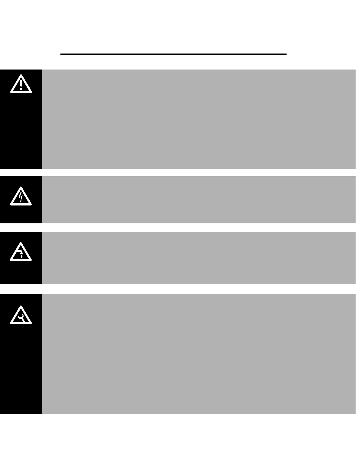
CAUTION: Servicing
Disconnect main power before any servicing.
The plumbing and electrical compartments contain high voltage components and
wiring. Access should be limited to authorized personnel only.
During and following operation of the humidifier, the steam and components in
contact with the steam such as the blower pack, steam lines, steam distributors,
and condensate lines can become hot and can burn if touched.
Nortec does not accept any liability for installations of humidity equipment
installed by unqualified personnel or the use of parts/components/equipment
that are not authorized or approved by Nortec.
CAUTION: Electrical
All electrical work should be done according to local and national electrical code.
Electrical connection to be performed by a licensed electrician.
CAUTION: Plumbing
Plumbing to be performed by a licensed plumber.
Drain water from humidifier can be very hot. Do not drain to public sink.
All plumbing work should be done according to local plumbing code.
CAUTION: Installation
Do not mount on hot surfaces.
Do not mount in area where freezing can occur.
Do not mount on vibrating surface.
Do not mount on floor.
The RH2 produces steam at atmospheric pressure. No devices which could block
steam output should be connected to the steam outlet.
Steam lines must be installed so that no restriction can produce backpressure in
the humidifier.
Regardless of selecting on/off or modulating control method, Nortec humidifiers
must have a closed circuit across its on/off security loop control terminal to
operate. Nortec highly recommends the use of a high limit humidistat.
Introduction | 2
Receiving and Unpacking
1 Check packing slip to ensure ALL material has been delivered.
2 All material shortages are to be reported to Nortec within 48 hours from receipt of goods.
Nortec assumes no responsibility for any material shortages beyond this period.
3 Inspect shipping boxes for damage and note damages on shipping waybill accordingly.
4 After unpacking, inspect equipment for damage and if damage is found, notify the shipper
promptly.
5 All Nortec products are shipped on a Free-On-Board (FOB) factory basis. Any and all damage,
breakage or loss claims are to be made directly to the shipping company.
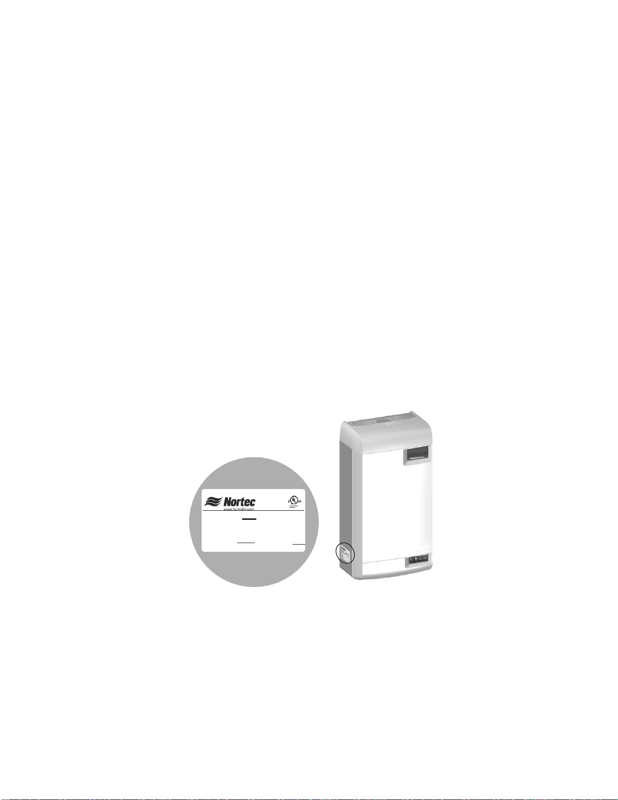
Before Installation
1 Ensure that available voltage and phase corresponds with humidifier voltage and phase as
indicated on humidifier’s specification label.
2 Ensure that the dedicated external fuse disconnect is of sufficient size to handle the rated
amps as indicated on the specification label. Refer to local codes.
3 Report any discrepancy immediately to the site engineer, if applicable.
4 Ensure sufficient clearances will be available as described in the Location section on pg 7.
5 Ensure steam lines can be routed to duct distributor or blower pack as described in Steam
Lines and Condensate Return Instructions on page 12.
Figure 1: Specification Label Location
MADE IN CANADA
MODEL:
VOLTS 1:
F.L.A:
KW:
XXXXXXXXXXXXXXXXXXXXXXXX S/N:XXXXXXX
XXXXXX XXX
PHASE:XXXX HZ:
XXXXX
XXXXXX
DATE:
XXXXXXXXX
VOLTS 3: XXXXXX XXX
VOLTS 2: XX XXXX XXX
F.L.A:XXXXX
F.L.A:XXXXX
XXXXXX
XXXXXX
KW:
KW:
3 | Introduction
RH2 Models
The RH2 is the most advanced residential steam humidifier available and provides steady and
reliable humidification for a home using the same proven cylinder technology as Nortec’s
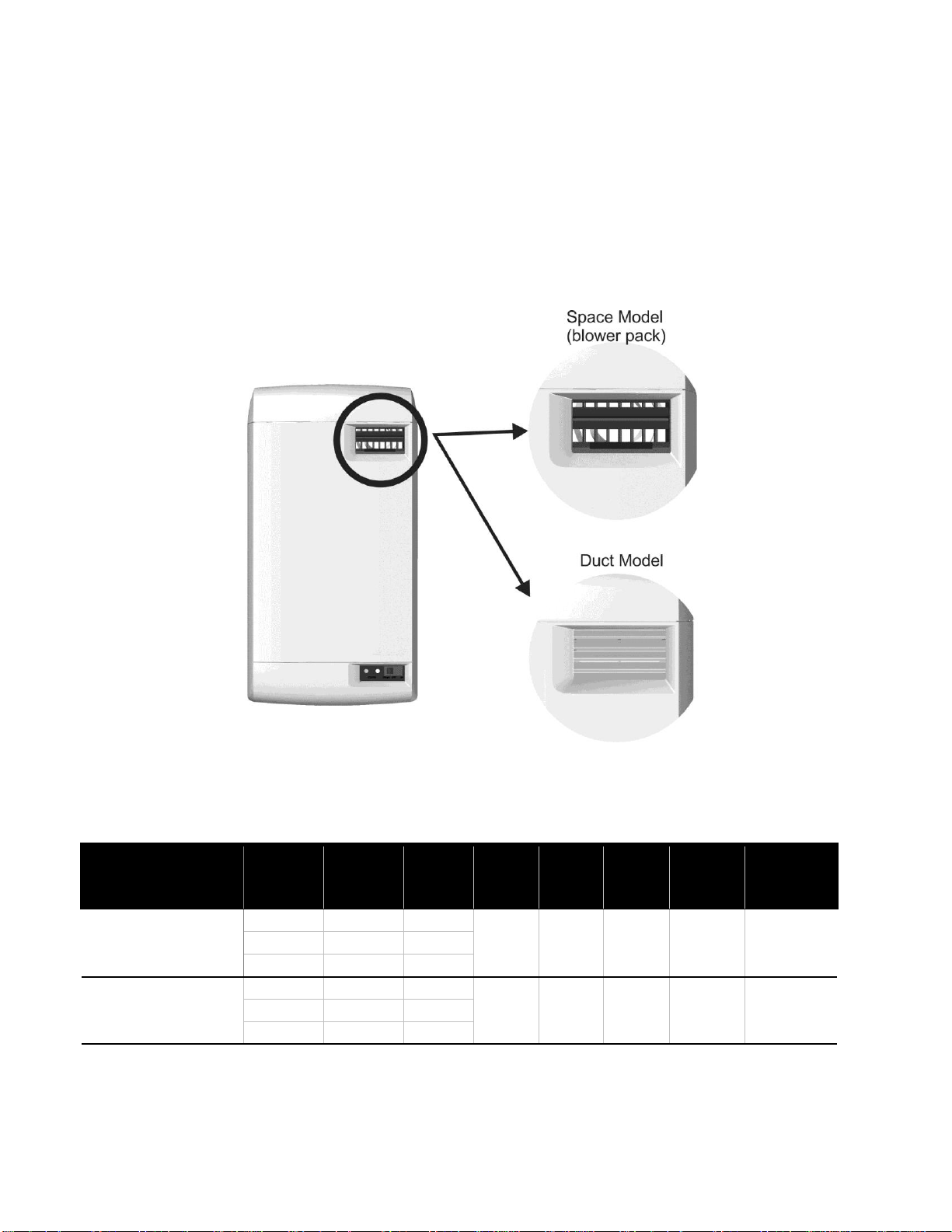
industrial electrode platform. The RH2 is available in 2 models: Duct, and Space. The duct
model is designed for connection to a steam distributor installed in a supply air duct, or for
connection to a remote blower pack. The space model is designed for applications where
humidity is to be introduced directly into the conditioned environment. The two models can be
differentiated by the grille in the humidifiers front cover, see Figure 2: RH2 Models.
.
Figure 2: RH2 Models
Table 1: RH2 Specifications
Model - Part No.
Volts
Capacity
lb (kg)
KW
Amps
Phase
Max Ext
Fuse
Standard
Cylinder
Net/Full
Weight
lb (kg)
RH2 Space - 2560952
110-120
4 (1.8)
1.5
1
20
202
16 / 22
(7.5 / 10.0)
208
6.9 (3.1)
2.6
12.7
220-240
8 (3.6)
3.0
RH2 Duct - 2560953
110-120
5 (2.3)
1.9
1
20
202
15 / 21
(7.0 / 9.5)
208
8.7 (4.0)
3.3
15.9
220-240
10 (4.6)
3.8

Introduction | 4
Options and Accessories
Nortec provides a complete line of options and accessories for every humidification application.
The following options and accessories are available and may have been delivered with your RH2
humidifier. Refer to the installation instructions that came with the accessories for proper
installation and operation.
Table 2: Options and Accessories
Option / Accessory
Application
Steam Distributors
Introducing steam into ventilation ducts.
Remote Blower Pack
Introducing steam into conditioned environments.
Digital or Modulating Control Humidistats
Controlling the output of the humidifier based on sensed RH.
Digital or Modulating High Limit
Humidistats
Preventing over-humidification in a duct by shutting down or
throttling down the humidifier when RH approaches saturation.
Air Proving Switches
Ensuring humidification only occurs when air is moving in a duct.

5 | Installation
Installation
6 Typical RH2 Installation
7 Location
8 Mounting with Keyholes
9 Plumbing
10 Steam Distributor
12 Steam and Condensate Returns
16 Electrical
17 External Controls
17 Control Wiring
17 Duct Humidification Control Location
18 Space Humidification Control Location
19 On/Off Control Wiring
20 Modulating Control Wiring
21 Fan Enable Wiring
21 RH2 Fan Control
21 Nortec On/Off Humidistat Fan Control
22 Options and Accessories
22 Remote Blower Pack
Installation | 6
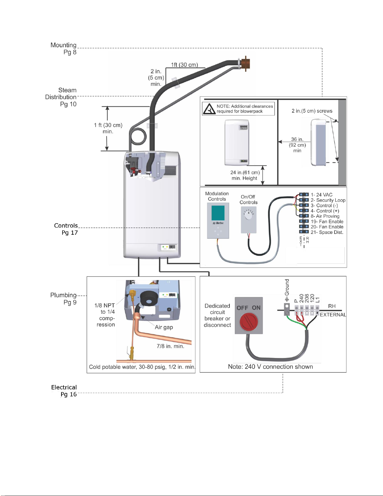
Typical RH2 Installation
Figure 3: Typical Humidifier Installation
2
7 | Installation
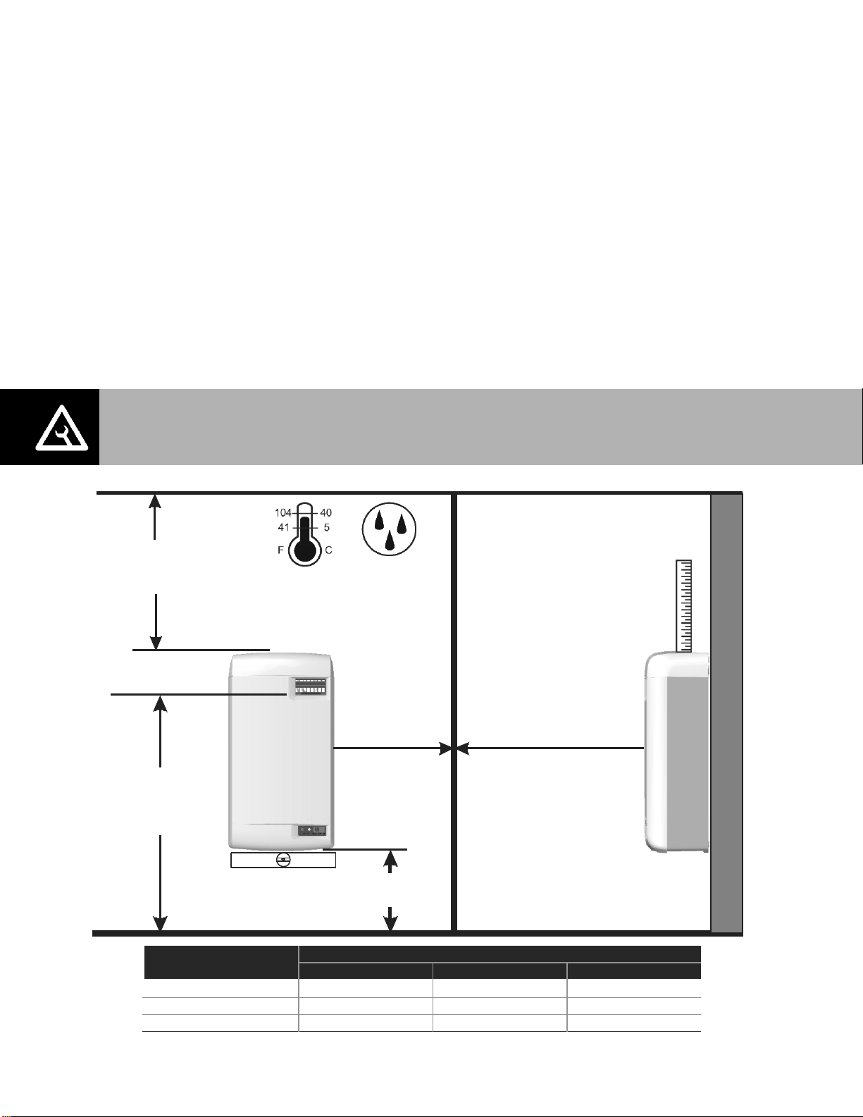
Location
Mount on a suitable wall or vertical surface. Do not sit the unit on the floor. Allow clearances
required for plumbing and electrical connections. Clearance dimensions shown are for
reference only and are the minimum required for maintenance of the humidifier. Consult local
and national codes before final location and installation. Nortec does not accept responsibility
for installation code violations.
Install only in areas with ambient temperature 41-104°F (5 – 40°C) relative humidity
5 - 95%.
When possible install below the steam distributor. Take care to provide proper steam line
routing and proper condensate traps.
DO NOT locate the humidifier any further then absolutely necessary from the steam
distributor location as net output will be reduced as a result of heat loss through the steam
line.
When possible, mount the RH2 humidifier at a height convenient for servicing.
Figure 4: Mounting Location / Clearance
Side clearance
for space models
only, see table
36 in. (92 cm)
in. ront learance
duct model
m f c
Additional front clearance
for space models,
see table
24 in.(61 cm)
Min Height
Mount Humidifier
Level
As Close as
Possible to Steam
Distributor
5-95%
Overhead clearance
for space models
only, see table
Humidifier Output lb (kg) Side in. (cm)
<4 (1.8) 12 (30) 12 (30)
6 (2.7) 16 (40) 18 (46)
8 (3.6) 18 (46) 18 (46)
7 ft (2.1 m)
min. Height
for space
models only.
36 (92)
42 (107)
48 (120)
Additional Clearance for Space Models Only
Overhead in. (cm) Front in. (cm)
Note: Do not mount on hot surfaces, where freezing can occur, vibrating surface, or floor.
Installation | 8
Mounting with Keyholes
1 The RH2 humidifier is wall mounted using a keyhole located on the back of the unit
cabinetry.
2 Use #8 x 2 in. (5 cm) screws mounted into 2x4 studs or better. 2 screws are needed, one for
hanging the unit and one for securing so it will not lift off the keyhole.
3 Install the top screw so that 1/4 in. (6 mm) is exposed. Raise the unit and place the screw
head through the keyhole.
4 Make sure the unit is level and then insert and tighten the second screw through the bottom
hole. Tighten the top screw. See Figure 5: Mounting With Keyholes.
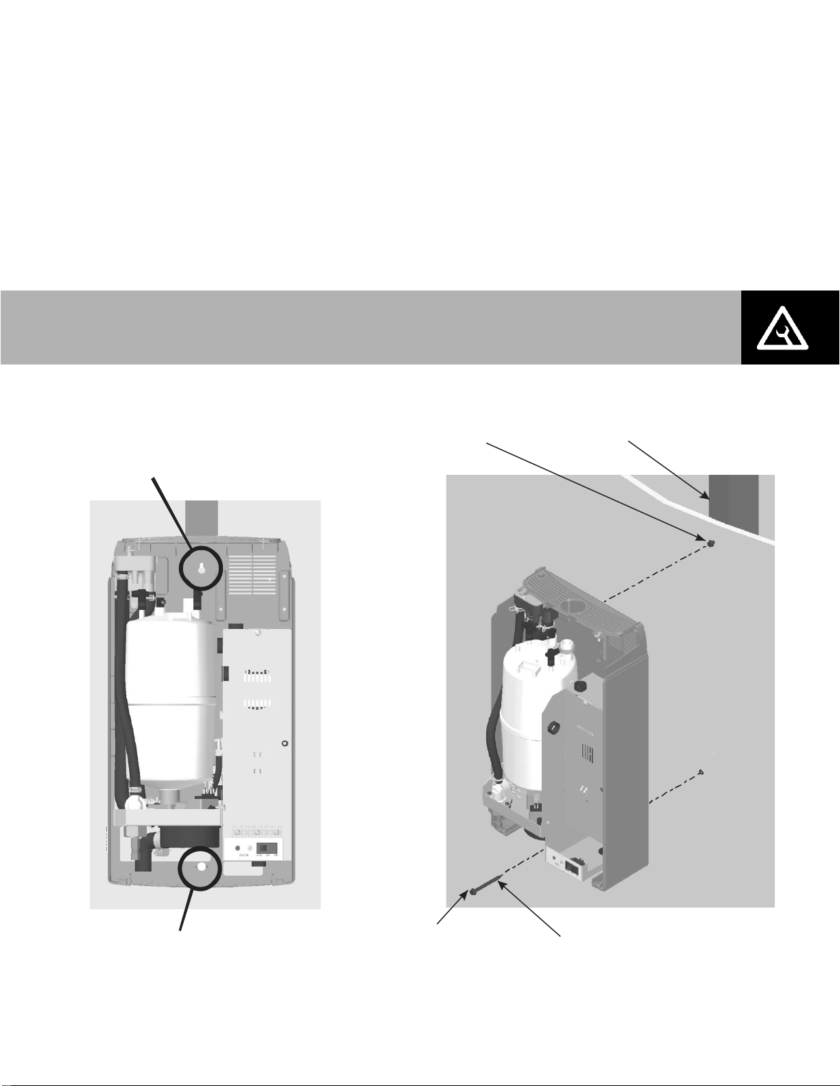
Figure 5: Mounting With Keyholes
Note: Use screws longer than 2” (5 cm) if drywall or other spacer is present.
Install Second Screw
after hanging
humidifier
#8 x 2 in. (5 cm)
Wood Screws
Insert screw so that
1/4 in. (6 mm) exposed,
hang unit, tighten
screw.
2x4 or Other
Structural
Member
Keyhole
Hole
9 | Installation
Plumbing
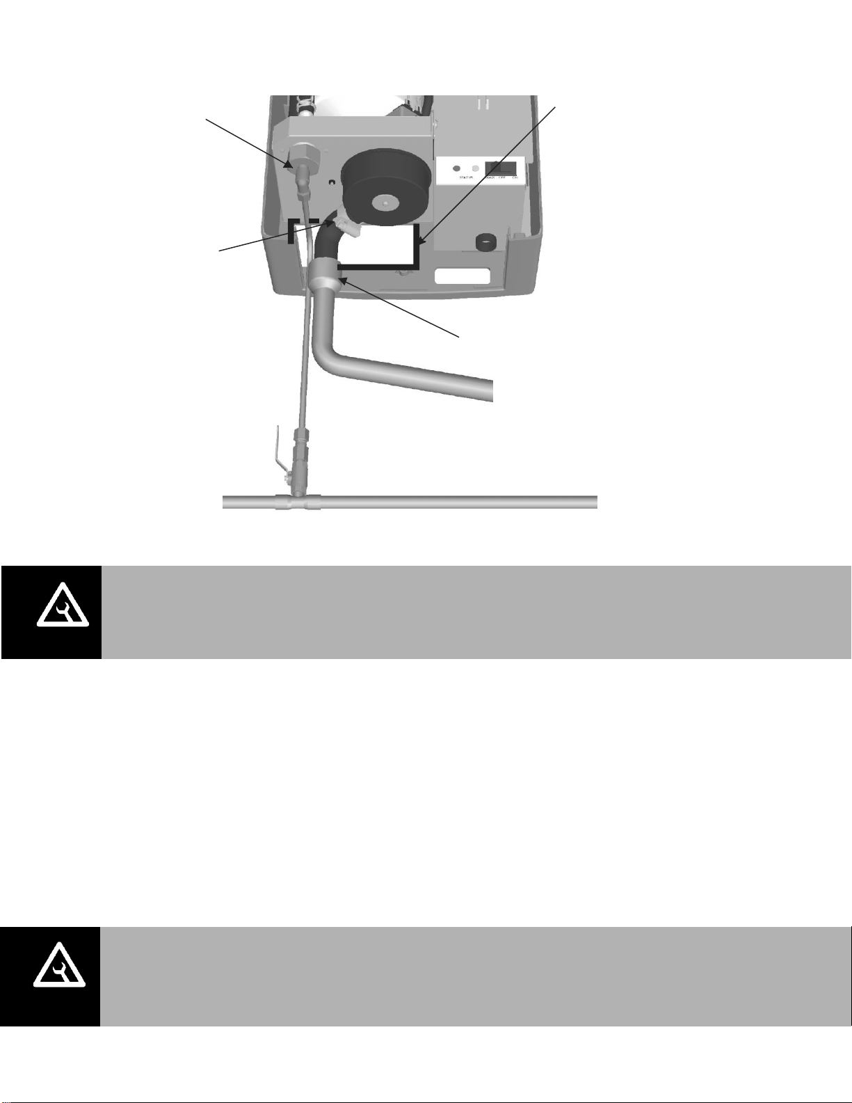
Figure 6: Water Supply and Drain Connection
Supply water should at 30 to 80 PSIG and be between 150-1200 Microsiemens
(330-670 S optimal range). Consult factory for water conditions outside of this range. Do
not use reverse osmosis or de-ionized water. Supply water should be cold (34-68ºF/1-20ºC).
Install water shut off valve before humidifier to facilitate servicing.
The drain line should not end in a sink used frequently by personnel, or where plumbing
codes prohibit it. Route to a floor drain or equivalent for safety reasons.
Ensure drain line is adequately sized to provide free and easy draining and that an air gap is
installed as shown. A restricted drain can cause cylinder water to over concentrate and
result in poor operation.
If a drain is not located near the humidifier use a condensate pump rated for hot drain water
such as Nortec’s Part Number 1429527.
1.2 in. (30 mm). OD
un-threaded outlet
with factory supplied
bent hose and clamp.
Always install a water
shut-off valve.
1/8 in. NPT
Use 1/4 in.
compression
fitting to connect
supply line to
unit.
*Pipe and water shut-off valve not supplied by Nortec.
Use 1/2 in. OD copper to within 4 ft (1.2 m) of humidifier
Note:
1 Fill and drain lines
can also be routed
through opening in
back of cabinet.
2 Optional cover
2548313 Is available
to conceal plumbing
connections.
Air gap required. 2 1/2 in. to 7/8 in.
Copper reducer is ideal. (NORTEC option
P/N 2522172) Hose must not
touch the bottom of the funnel.
Min. 7/8 in. OD drain line.
Keep as short as possible.
Slope down to floor
drain or main drain.
All water supply and drain line connections should be installed in accordance with
local plumbing codes.
Drain water is automatically cooled to 140°F (60°C). Drain material must be
rated for this temperature.
For humidifiers installed in some cities including the City of Los Angeles:
A city-approved spring-loaded double ball CHECK VALVE must be installed by
contractor on the potable water inlet to the humidifier. Recommended valve
manufacturer: Watts Regulator, phone number 508-688-1811, Size depending on
supply line 1/4”, 3/8”, or 1/2” NPT inlet and outlet, Model #7.
Installation | 10
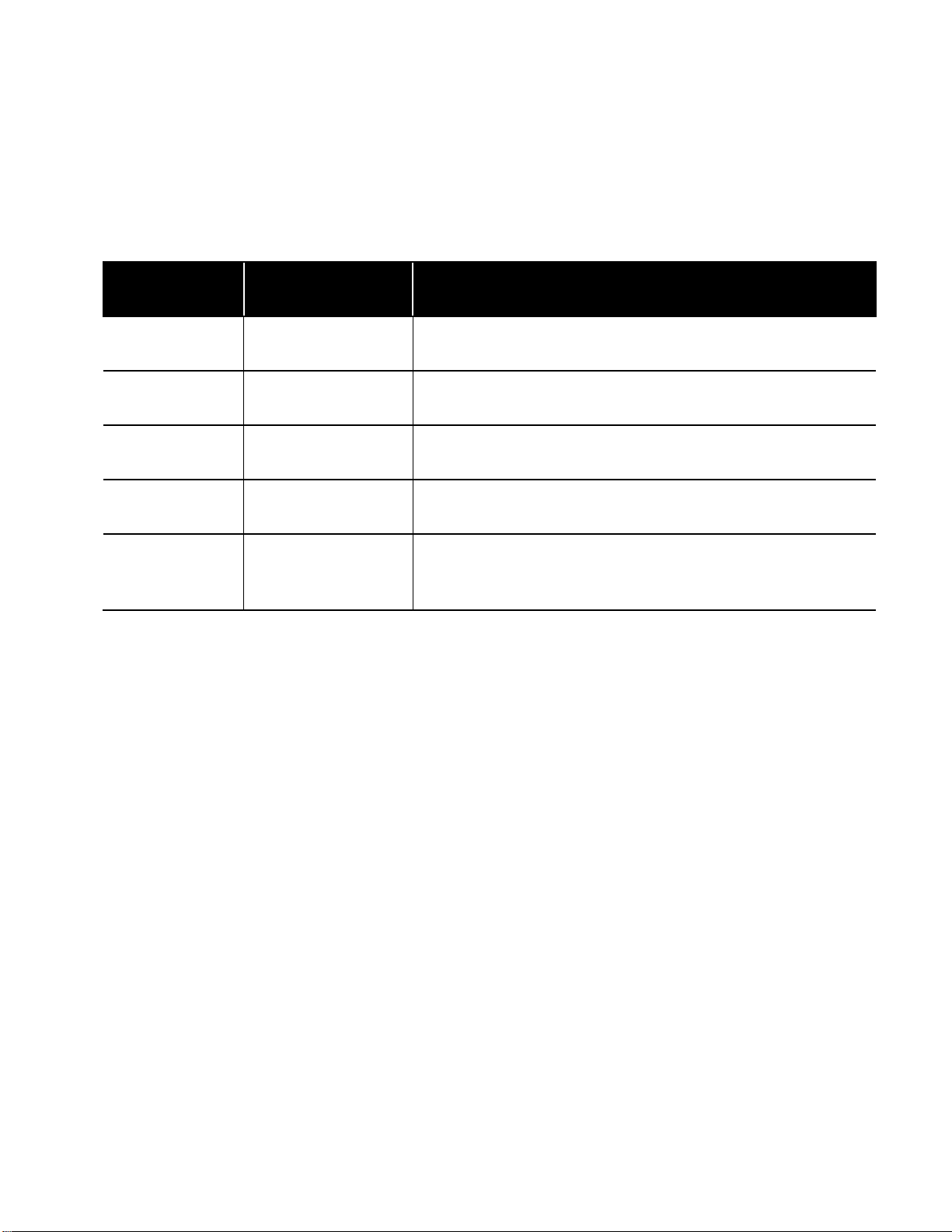
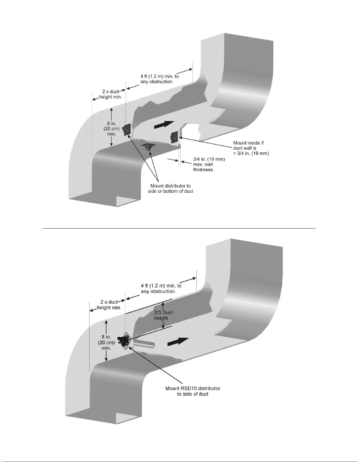
Steam Distributor
Steam generated by the RH2 Space is blown directly into the space by the integrated blower
pack. The RH2 Duct requires a steam distributor, installed in the ventilation duct. The RH2
Duct can distribute steam into a ventilation duct using the following distributor options in
Table 3.
Table 3: RH2 Duct Steam Distributor Options
Nortec Part
Number
Option Description
Notes
1581820
Nozzle Distributor Kit
Includes a steam distribution nozzle, steam hose, condensate hose,
and installation hardware. See Figure 7.
2553708
RSD 10 Distributor Kit
Includes a steam distributor, steam hose, condensate hose, and
installation hardware. See Figure 8.
Select to duct
dimensions
ASD Duct Distributor
Used when duct width exceeds 12”. Refer to Distributor manual or
HELP software for selection.
Select to duct
dimensions
Mini SAM-e
Used when short absorption is necessary. Refer to SAM-e manual
or HELP software for selection.
2564776
RMBP for RH2 Duct
Remote Mounted Blower Pack, used with the RH2 Duct, adds steam
directly into the space. The blower pack is installed remote to the
humidifier.
Whichever method is used, the steam distributor should be installed as close as possible to
the humidifier. Short steam distribution lines minimize condensate losses and the
possibility of generating backpressure in the steam distribution line.
11 | Installation
Figure 7: RH2 Duct Nozzle Distributor Installation
Figure 8: RH2 Duct RSD10 Distributor Installation
Installation | 12
Steam Lines and Condensate Return Instructions
The following instructions must be followed for installation of steam lines for the RH2 Duct.
Failure to use recommended material and exceeding maximum recommended length in Table
4, or failure to follow any other steam line installation instructions will result in improper
operation and could void the warranty.
Table 4: Recommended Steam Line Material for RH2 Duct
Voltage
Steam Output
Material*
Maximum
Steam Line
Length
Possible Losses
lbs/hr
(kg/hr)
Nortec Steam
Hose
MED-L
Copper
Tube
Stainless
Steel
Tube
ft
(m)
lbs/hr
(kg/hr)
110-
120V
5
(2.3)
Part Number
1328810
(7/8”)
3/4”
0.875 X
0.049W
7
(2)
0.5
(0.2)
208V
8.7
(3.3)
10
(3)
1
(0.5)
220-
240V
10
(4.6)
12
(3.5)
1.5
(0.7)
Oversized Steam Line (used for longer steam runs)**
110-
120V
Not
Recommended
Not
Recommended
1”
1.125 X
0.049W
Not Recommended
208V
8.7
(3.3)
12
(3.5)
2
(0.9)
220-
240V
10
(4.6)
24
(7)
3
(1.4)
Note: * The use of steam line other than copper, stainless steel tube or Nortec supplied steam line will void the warranty and may adversely
affect the operation of the humidifier.
** These diameters require a reducer at humidifier and steam distributor connection. Use Nortec part number 1115444 at
humidifier to prevent backpressure caused by condensation collecting at the reduction.
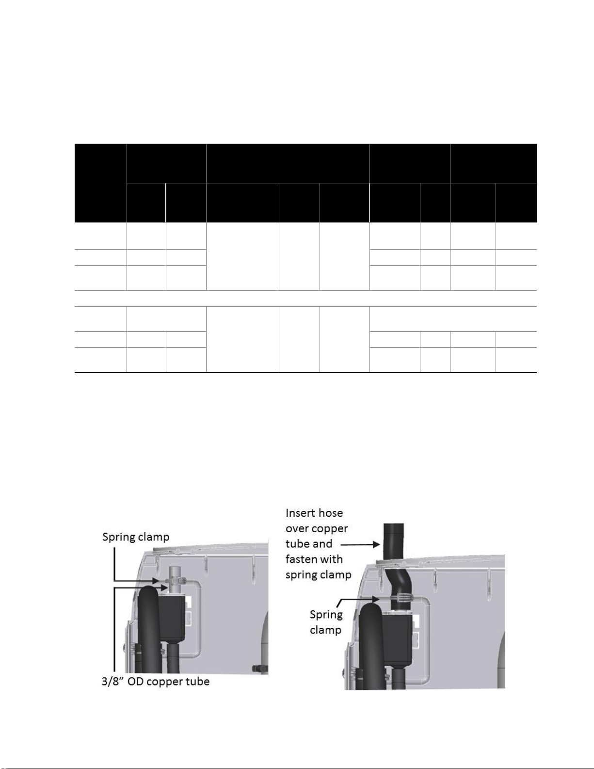
To return condensate for RH2+, insert copper tube (supplied with equipment) half way into the
condensate opening of the fill cup along with the spring clamp (supplied with equipment).
Insert the condensate hose into the condensate return hole at the top of the RH unit, and over
the copper tube. Fasten in place with the spring clamp.
Figure 9: Condensate Return
13 | Installation
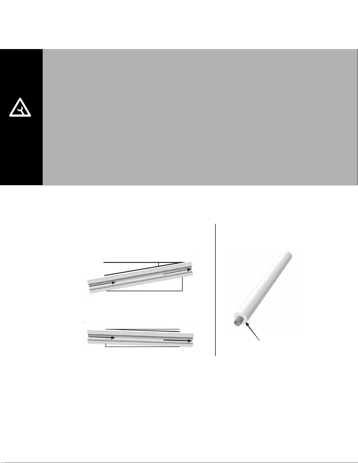
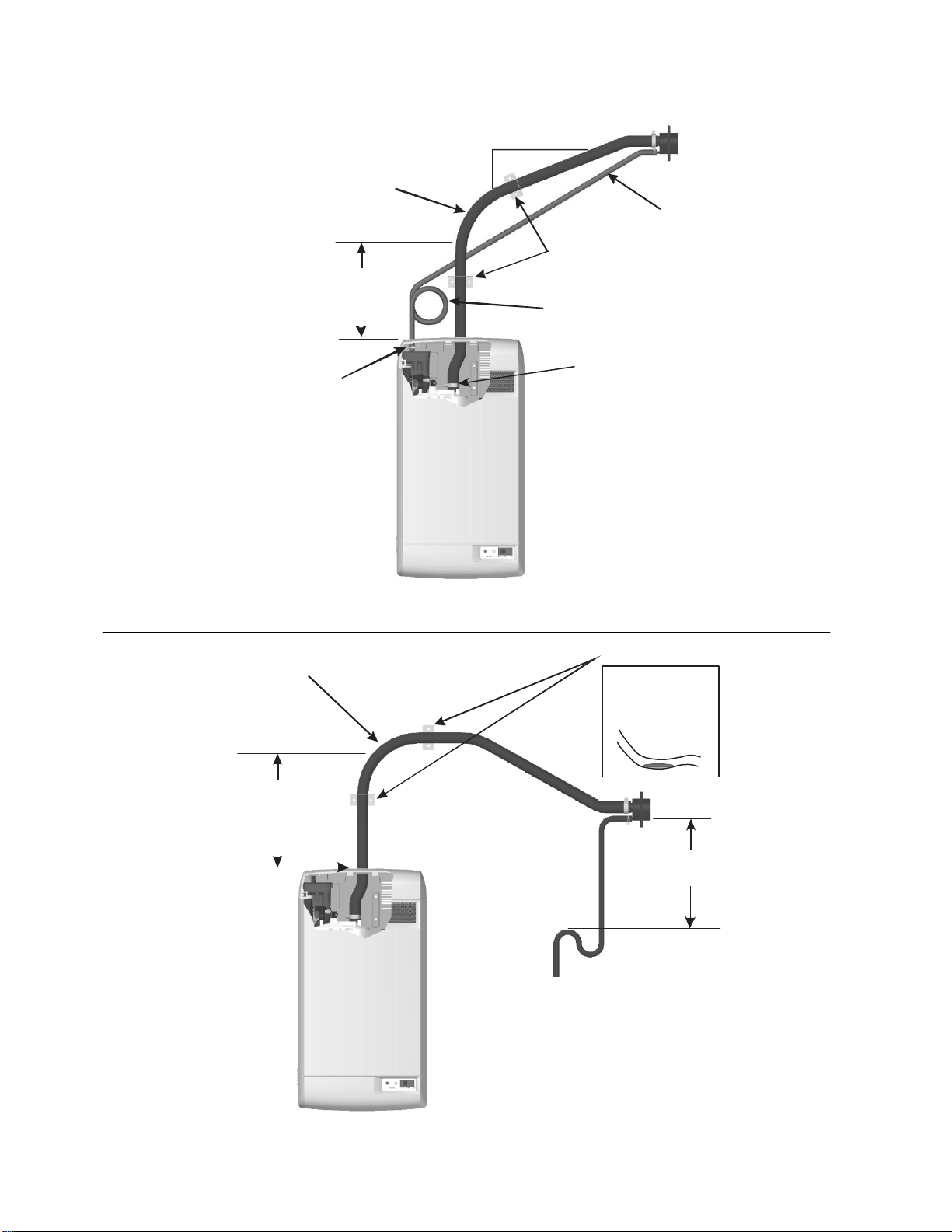
Figure 10: Main Steam Line Requirements
MAIN RULES FOR ATMOSPHERIC STEAM LINES
Steam lines must not have any restrictions which could result in back pressure.
Follow recommended materials, size and length, see tables.
Slope the steam lines.
Insulate with 1.0 in. (2.5 cm) pipe insulation
Trap condensate (Use full size ‘T’ for Traps)
Do not over tighten hose clamp at cylinder steam outlet. The maximum torque is 12
in-lbs.
Support steam line so weight is not on cylinder.
Condensate traps must be a minimum of 6 in. (15 cm) in height or duct static
pressure + 2 in. (5 cm), whichever is greater.
Trapping by P-trap or pigtail. Support line as necessary to ensure it remains free of
kinks.
S
t
e
a
m
D
i
r
e
c
t
i
o
n
S
t
e
a
m
D
i
r
e
c
t
i
o
n
S
t
e
a
m
D
i
r
e
c
t
i
o
n
2 in.
(5 cm)
1 ft (30 cm)
1ft (30 cm)
0.5 in.
(12 mm)
10 Degrees
2 Degrees
Use Appropriate Slope Insulate Pipe
1 in. (2.5 cm) pipe
insulation
Installation | 14
Figure 11: Steam Distributor Above Humidifier (Hose)
Figure 12: Steam Distributor Below Humidifier (Hose)
Condensate
Trap
1 ft (30 cm)
min. Before
any bend
Min 12 in.
(30 cm)
radius
Hose will soften
over time
proper support
Is necessary
Support Brackets
1 ft (30 cm)
min.
To Drain
1 ft (30 cm)
min. before
any bend
12 in.(30 cm)
min. Radius
Condensate
Trap
Condensate
line
Connect Steam
Hose to CylinderConnect Condensate
Hose to Fill Cup
2 in. (5 cm)
min.
1 ft (30 cm)
Support
Brackets
15 | Installation
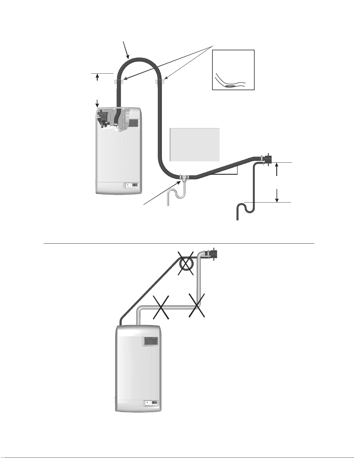
Figure 13: Steam Distributor Below Humidifier With Obstruction (Hose)
Figure 14: Common Steam Line Errors
Steam line
not sloped
No condensate
trap at vertical
transition
Condensate trap
not 12 in (30 cm)
below distributor
1ft (30 cm)
min. before
any bend
12 in.
(30 cm)
min.
radius
Obstruction
Use full size condensate tee
at low point. Slope lines up
to “T” and immediately after it.
Hose will soften
over time
proper support
Is necessary
Support brackets
1 ft (30 cm)
min.
To drain
To drain
2 in.
(5 cm)
min.1 ft (30 cm)
Installation | 16
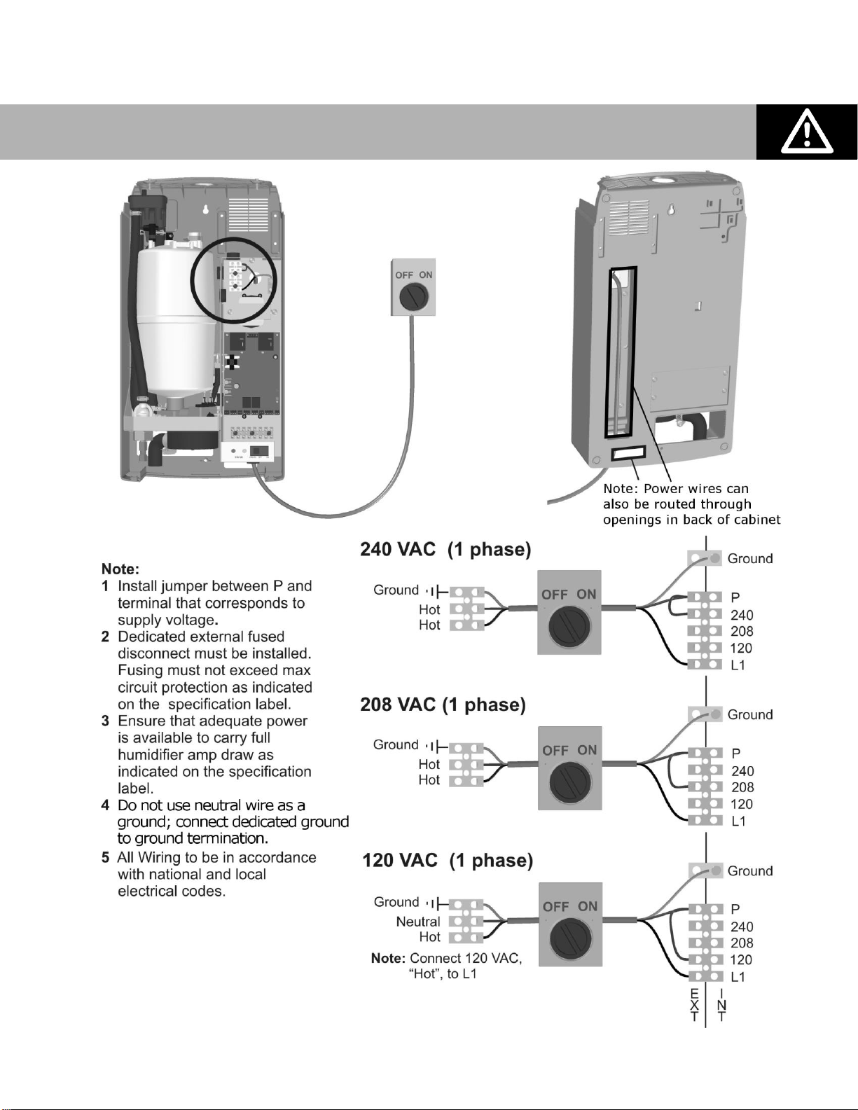
Electrical
Figure 15: Primary Power Connection
Caution: Wiring to be performed by a licensed Electrician.
 Loading...