


Important: Read and save these instructions. This guide to be left with equipment.
 NH-EL Series
Installation and Operation Manual
Includes installation, operation maintenance and troubleshooting information for your NH-EL Electric Steam humidifier
2570435 D | 25 JUN 2014

Thank you for choosing Nortec.
INSTALLATION DATE (MM/DD/YYYY)
MODEL #
SERIAL #
CYLINDER #
Proprietary Notice
This document and the information disclosed herein are proprietary data of Nortec Humidity Ltd. Neither this document nor the information contained herein shall be reproduced, used, or disclosed to others without the written authorization of Nortec Humidity Ltd., except to the extent required for installation or maintenance of recipient’s equipment.
Liability Notice
Nortec does not accept any liability for installations of humidity equipment installed by unqualified personnel or the use of parts/components/equipment that are not authorized or approved by Nortec.
Copyright Notice
Copyright 2014, Nortec Humidity Ltd. All rights reserved.

Contents
1Introduction
2Receiving and Unpacking
3Humidifier Components
5NH-EL Models
6Options and Accessories
9Installation
10Typical Humidifier Installation
11Location
13Mounting with Keyholes
14Plumbing
15Steam Distributor
16Steam Lines and Condensate Returns
21Electrical
22External Controls
36 Options and Accessories
38Start Up
39Installation Check
40NH-EL User Interface
41Start Up Procedure
42Information Screens
43Nortec Digital Controls
46NH-EL Pre-Start Up Checklist
47NH-EL Start Up Checklist
48Operation
49LED Status Lights
51 How the Humidifier Works
54 NH-EL Humidifier Configuration
62Maintenance and Servicing
63Required Maintenance
68Extended Shutdown
69NH-EL Maintenance Checklist
70Troubleshooting
72 General Troubleshooting
75 NH-EL Warnings and Faults
81NH-EL Wiring Diagram (Cylinder A)
82NH-EL Wiring Diagram (Cylinder B)
83Spare Parts
95 Warranty
Introduction
CAUTION: Servicing
Disconnect main power before any servicing.
The plumbing and electrical compartments contain high voltage components and wiring. Access should be limited to authorized personnel only.
During and following operation of the humidifier, the steam and components in contact with the steam such as the cylinder, blower pack, steam lines, steam distributors, and condensate lines can become hot and can burn if touched.
Nortec Humidity Ltd. does not accept any liability for installations of humidity equipment installed by unqualified personnel or the use of parts/components/equipment that are not authorized or approved by Nortec Humidity Ltd.
CAUTION: Electrical
All electrical work should be done according to local electrical code.
Electrical connection to be performed by a licensed electrician.
CAUTION: Plumbing
Plumbing to be performed by a licensed plumber.
Drain water from humidifier can be very hot. Do not drain to public sink.
All plumbing work should be done according to local plumbing code.
CAUTION: Installation
Do not mount on hot surfaces.
Do not mount in area where freezing can occur.
Do not mount on vibrating surface.
Do not mount on floor.
The NH-EL produces steam at atmospheric pressure; no devices which could block steam output should be connected to the steam outlet.
Steam lines must be installed so that no restriction can produce back pressure in the humidifier. Failure to follow installation instructions will result in improper operation and could void warranty.
Regardless of selecting On/Off or modulating control method, NORTEC humidifiers must have a closed circuit across its On/Off security loop control terminal to operate. NORTEC highly recommends the use of a high limit humidistat and an air proving switch in series for this function.
1 | Introduction
Receiving and Unpacking
1Check packing slip to ensure ALL material has been delivered.
2All material shortages are to be reported to NORTEC within 48 hours from receipt of goods. NORTEC assumes no responsibility for any material shortages beyond this period.
3Inspect shipping boxes for damage and note damages on shipping waybill accordingly.
4After unpacking, inspect equipment for damage and if damage is found, notify the shipper promptly.
5All NORTEC products are shipped on a Free-On-Board (FOB) factory basis. Any and all damage, breakage or loss claims are to be made directly to the shipping company.
Before Installation
1Ensure that available voltage and phase corresponds with humidifier voltage and phase as indicated on humidifier’s specification label.
2Ensure that the dedicated external fuse disconnect is of sufficient size to handle the rated amps as indicated on the specification label. Refer to local codes.
3Report any discrepancy immediately to the site engineer.
4Ensure sufficient clearances will be available as described in Location on page 11.
5Ensure steam lines can be routed to distributor or blower pack as described in Steam Lines and Condensate Return on page 16.
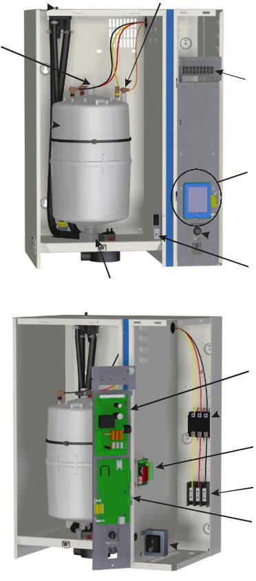
Figure 1: Specification Label Location
Introduction | 2
Humidifier Components
Condensate Return 
Fill Cup 
Steam Outlet
Cylinder Plug
Cylinder 
Cylinder Strap
Fill Valve
Drain Canal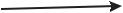
High Water Sensor |
|
Plug |
NOTE: |
|
|
|
NH-EL 005-030 |
|
shown, component |
|
location may vary |
|
slightly for other |
|
models. |
|
Control Terminal |
|
Strip |
Touch Screen Display
 Auxiliary Drain Switch
 On/Off Switch
Door Interlock Switch
Drain Valve
Driver Board
 Contactor
Remote Relay Board
High Voltage
Terminal Block
Integrated Controller
 Transformer
Figure 2: NH-EL Humidifier Components
3 | Introduction
Description of Components
|
Table 1: Humidifier Components |
|
|
Component |
Function of Component |
|
|
Auxiliary Drain |
Drains water from cylinder by activating drain valve. Note that initiating a |
|
drain in this manner will not induce Drain Water Cooling. |
|
|
Condensate Return |
Provides a connection to return condensate to humidifier. |
|
|
Contactor |
Turns On/Off power to cylinder electrodes. |
|
|
Control Terminal |
Terminal strip for connecting external controls and blower pack to |
Strip |
humidifier. |
|
|
Cylinder Plug |
Power connectors to electrodes in cylinder. |
|
|
Cylinder strap |
Securely holds cylinder in place. |
|
|
Cylinder |
Holds electrodes in water. Current between electrodes generates heat used |
|
to generate steam. |
|
|
Touch Screen |
User interface for configuring the humidifier. |
Display |
|
|
|
Door Interlock |
Prevents contactor from engaging when door is removed (pull out to |
Switch |
override this safety feature while troubleshooting). |
|
|
Drain Canal |
Combines cylinder drain water and fill cup overflow into a single drain outlet. |
|
|
Drain Valve |
Drains water from cylinder. |
|
|
Driver Board |
Provides input and output connections to humidifier components. |
|
|
Fill Cup |
Provides an air gap for backflow prevention. |
|
|
Fill Valve |
Controls flow of water into humidifier. |
|
|
High Voltage |
Primary power connection from remote disconnect to humidifier. |
Terminal Block |
|
|
|
High Water sensor |
Used to detect max water level in cylinder. |
Plug |
|
|
|
On/Off Switch |
Turns power On/Off to humidifier controller. Note: Turn off humidifier |
|
disconnect to shut off primary power to the humidifier. |
|
|
Remote Relay |
Provides a terminal strip to dry contacts which open/close to indicate the |
Board (option) |
humidifier is on, humidifying, needs service, or is in a fault condition. |
|
|
Steam Outlet |
Connect to steam line with steam hose. |
|
|
Integrated |
Controls all functions of the humidifier’s operation and provides user |
Controller |
interface for configuration of the humidifier. |
|
|
Transformer |
Steps primary voltage down to 24 VAC for the controller and internal |
|
components such as the fill valve and drain valve. |
|
|
Introduction | 4
NH-EL Models
The NH-EL with its Integrated Controller and state-of-the-art features and options is the most advanced electrode steam humidifier available. As well as controlling the operation of the humidifier, the Integrated Controller can be connected directly to BACnet and to the Internet. The NH-EL is available in capacities ranging from 5 lb/hr (2 kg/hr) to 200 lb/hr (90 kg/hr). NHEL humidifiers are packaged in three different cabinets depending on capacity. Figure 3: NH-EL Sizes shows the configuration and relative size of the three different cabinets. NH-EL models up to 100 lb/hr (45 kg/hr) are also available with a built on blower pack. Table 3 provides specifications for the NH-EL product line.
NH-EL 005-030 |
NH-EL 050-100 |
NH-EL 150-200 |
Fill Connections Drain Connections
Figure 3: NH-EL Sizes
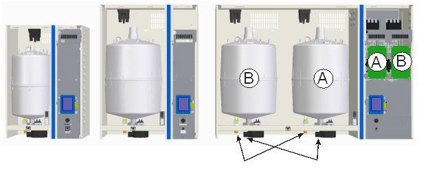
Double Unit (NH-EL 150-200)
NH-EL double units have two cylinders to provide increased capacity. The construction and installation of double units is identical to units with a single cylinder with the following exceptions:
Double units have two driver boards (designated A and B). One driver board controls each cylinder. (See Figure 3: NH-EL Sizes).
Double units can operate both cylinders in series or parallel from a single set of control signals or independently based on two sets of control signals (see Double Mode (NH-EL 150200 only) on page 56 for configuration instructions).
Independent Operation - If configured for independent operation then 2 sets of control wiring must be provided. Control wiring for each cylinder must be connected to the cylinder’s corresponding driver board/terminal strip and each cylinder performs independent of the other.
Parallel Operation - If configured for parallel operation then only one set of control wiring is required and the cylinders operate in parallel. The advantage is even wear on both cylinders.
Series Operation – If configured for series operation, then only one set of control wiring is required and the cylinders operate in series. Cylinder A’s output range is 0-50% and Cylinder B’s output range is 50-100%. The advantage is the lower turndown ratio of one cylinder.
Double units have one primary power connection but have individual fill, drain, and steam outlet connections for each cylinder.
5 | Introduction
Options and Accessories
NORTEC provides a complete line of options and accessories for every humidification application. The following options and accessories are available and may have been delivered with your NH-EL humidifier. Refer to the installation instructions that came with the accessories for the proper installation and operation.
Table 2: Options and Accessories |
|
|
|
Option / Accessory |
Application |
Steam Distributors |
Adding steam into air ducts. |
Remote Blower Pack |
Adding steam into a space remote from the humidifier. |
SAMe Steam Distribution Manifold |
Adding steam into air ducts where short absorption is required. |
Digital or Analog Control Humidistats |
Controlling the output of the humidifier based on sensed RH (can |
|
be mounted in the space being humidified or in the duct). |
Digital RH Transducers |
Communicating RH in a space or duct to the humidifier. |
Digital or Analog High Limit Humidistats |
Preventing over humidification in a duct by shutting down or |
|
throttling down the humidifier when duct RH gets high. |
Air Proving Switches |
Ensuring humidification only occurs when air is moving in a duct. |
Fill Cup Extension |
Increasing the steam back pressure capability of an NH-EL. |
Drain Water Cooling (Extreme) |
Cooling drain water to less than 120 °F (49°C). |
Foam Detection Kits |
Increasing the range of water quality in which an NH-EL can |
|
operate. |
|
|
Introduction | 6

|
|
|
Table 3: NH-EL Specifications |
|
|
|
||||
|
Capacity |
|
NH-EL |
|
Max |
|
Stand- |
Fill |
Net/Full |
|
Phase |
Volts |
Amps |
Ext |
KW |
ard |
gal (l) |
Weight |
|||
lb (kg) |
Part No. |
|||||||||
|
|
|
Fuse |
|
Cylinder |
per min |
lb (kg) |
|||
|
|
|
|
|
|
|||||
|
5 (2.3) |
110-120 |
2573379 |
15.6 |
20 |
1.9 |
202 |
0.13 (0.5) |
|
|
|
|
208 |
2573380 |
18.3 |
25 |
3.8 |
202 |
|
|
|
|
|
|
|
|
|
|
|
|
45/55 |
|
|
|
220-240 |
2573382 |
15.9 |
20 |
3.8 |
202 |
|
||
|
|
|
|
|||||||
|
|
|
|
|
|
|
|
0.13 |
|
|
|
10 (4.5) |
277 |
2573383 |
13.7 |
20 |
3.8 |
202 |
(21/25) |
||
|
(0.5) |
|||||||||
|
|
|
|
|
|
|
|
|||
|
|
440-480 |
2573385 |
7.9 |
15 |
3.8 |
204 |
|||
|
|
|
|
|||||||
|
|
|
|
|
|
|
|
|
|
|
1 |
|
550-600 |
2573386 |
6.3 |
15 |
3.8 |
204 |
|
|
|
|
|
208 |
2573388 |
36.6 |
45 |
7.6 |
321 |
|
|
|
|
|
|
|
|
|
|
|
|
|
|
|
|
220-240 |
2573389 |
31.7 |
40 |
7.6 |
321 |
|
|
|
|
|
|
|
|
|
|
|
0.13 |
|
|
|
20 (9) |
277 |
2573390 |
27.5 |
35 |
7.6 |
321 |
|
||
|
(0.5) |
|
||||||||
|
|
|
|
|
|
|
|
|
||
|
|
440-480 |
2573392 |
15.9 |
20 |
7.6 |
309 |
45/65 |
||
|
|
|
||||||||
|
|
|
|
|
|
|
|
|
||
|
|
550-600 |
2573393 |
12.7 |
20 |
7.6 |
309 |
|
|
|
|
|
|
|
|
|
|
|
|
(21/30) |
|
|
|
208 |
2573394 |
21.1 |
30 |
7.6 |
303 |
|
||
|
|
|
|
|||||||
|
|
|
|
|
|
|
|
|
|
|
|
20 (9) |
220-240 |
2573395 |
18.3 |
25 |
7.6 |
303 |
0.13 |
|
|
|
|
|
|
|
|
|
|
|||
|
440-480 |
2573397 |
9.2 |
15 |
7.6 |
311 |
(0.5) |
|
||
|
|
|
||||||||
|
|
|
|
|
|
|
|
|
|
|
|
|
550-600 |
2573398 |
7.3 |
15 |
7.6 |
311 |
|
|
|
|
|
|
|
|
|
|
|
|
|
|
|
|
208 |
2573399 |
31.7 |
40 |
11.4 |
421 |
|
|
|
|
|
|
|
|
|
|
|
|
|
|
|
30 |
220-240 |
2573400 |
27.5 |
35 |
11. 4 |
421 |
0.3 |
45/80 |
|
|
|
|
|
|
|
|
||||
|
(13.5) |
440-480 |
2573402 |
13.7 |
20 |
11.4 |
411 |
(1.2) |
(21/37) |
|
|
|
|
|
|
|
|
|
|
|
|
|
|
550-600 |
2573403 |
11.0 |
15 |
11.4 |
411 |
|
|
|
|
|
|
|
|
|
|
|
|
|
|
|
|
208 |
2573404 |
51.9 |
70 |
18.7 |
621 |
|
|
|
|
|
|
|
|
|
|
|
|
|
|
|
50 |
220-240 |
2573405 |
45.0 |
60 |
18.7 |
621 |
0.5 |
|
|
|
|
|
|
|
|
|
|
|||
|
(22.5) |
440-480 |
2573407 |
22.4 |
30 |
18.7 |
605 |
(2.0) |
|
|
|
|
|
|
|
|
|
|
|
|
|
|
|
550-600 |
2573408 |
18.0 |
25 |
18.7 |
605 |
|
|
|
|
|
|
|
|
|
|
|
|
|
|
|
|
208 |
2573409 |
77.9 |
100 |
28.1 |
621 |
|
|
|
|
|
|
|
|
|
|
|
|
85/150 |
|
3 |
75 (34) |
220-240 |
2573410 |
67.4 |
90 |
28.1 |
621 |
0.5 |
||
|
|
|
|
|
|
|
||||
440-480 |
2573412 |
33.8 |
45 |
28.1 |
605 |
(2.0) |
(39/68) |
|||
|
|
|||||||||
|
|
|
|
|
|
|
|
|
||
|
|
550-600 |
2573413 |
27.0 |
35 |
28.1 |
605 |
|
|
|
|
|
208 |
2573414 |
94.4 |
125 |
34.0 |
621 |
|
|
|
|
|
|
|
|
|
|
|
|
|
|
|
100 (45) |
220-240 |
2573415 |
90.0 |
125 |
37.4 |
621 |
0.9 |
|
|
|
|
|
|
|
|
|
|
|||
|
440-480 |
2573417 |
45.0 |
60 |
37.4 |
605 |
(3.3) |
|
||
|
|
|
||||||||
|
|
|
|
|
|
|
|
|
|
|
|
|
550-600 |
2573418 |
36.0 |
45 |
37.4 |
605 |
|
|
|
|
|
208 |
2573419 |
155.8 |
200 |
56.1 |
621 |
|
|
|
|
|
|
|
|
|
|
|
|
|
|
|
|
220-240 |
2573420 |
135.0 |
175 |
56.1 |
621 |
0.5** |
|
|
|
150 (68) |
|
|
|
|
|
|
|
||
|
440-480 |
2573422 |
67.4 |
90 |
56.1 |
605 |
(2.0**) |
|
||
|
|
|
||||||||
|
|
|
|
|
|
|
|
|
120/245 |
|
|
|
550-600 |
2573423 |
54.0 |
70 |
56.1 |
605 |
|
||
|
|
|
|
|
|
|
|
|
|
|
|
|
208 |
2573424 |
188.7 |
250 |
68.0 |
621 |
|
(55/112) |
|
|
|
|
|
|
|
|
|
|
||
|
200 (90) |
220-240 2573425 180.0 |
225 |
74.8 |
621 |
0.9** |
|
|||
|
440-480 |
2573427 |
90.0 |
125 |
74.8 |
605 |
(3.3**) |
|
||
|
|
|
||||||||
|
|
|
|
|
|
|
|
|
|
|
|
|
550-600 |
2573428 |
72.0 |
90 |
74.8 |
605 |
|
|
|
|
|
|
|
|
|
|
|
|
|
|
** Note: Per cylinder basis.
7 | Introduction
|
|
|
Table 4: NH-EL Space Specifications |
|
|
|||||
|
Capacity |
|
NH-EL |
|
Max |
|
Stand- |
Fill |
Net/Full |
|
Phase |
Volts |
Space |
Amps |
Ext |
KW |
ard |
gal (l) |
Weight |
||
lb (kg) |
||||||||||
|
|
Part No. |
|
Fuse |
|
Cylinder |
per min |
lb (kg) |
||
|
|
|
|
|
||||||
|
5 (2.3) |
110-120 |
2573429 |
17.2 |
25 |
2.0 |
202 |
0.13 (0.5) |
|
|
|
|
208 |
2573430 |
19 |
25 |
4.0 |
202 |
|
|
|
|
|
|
|
|
|
|
|
83/93 |
|
|
220-240 |
2573431 |
16.5 |
25 |
4.0 |
202 |
|
|
|
|
|
|
|
|
|
|
0.13 |
|
|
10 (4.5) |
277 |
2573432 |
14.2 |
20 |
4.0 |
202 |
(38/42) |
|
|
(0.5) |
||||||||
|
|
|
|
|
|
|
|
||
|
|
440-480 |
2573434 |
8.2 |
15 |
4.0 |
204 |
|
|
|
|
|
|
||||||
|
|
|
|
|
|
|
|
|
|
1 |
|
550-600 |
2573435 |
6.6 |
15 |
4.0 |
204 |
|
|
|
|
208 |
2573436 |
37.3 |
45 |
7.8 |
321 |
|
|
|
|
|
|
|
|
|
|
|
|
|
|
220-240 |
2573437 |
32.3 |
40 |
7.8 |
321 |
|
|
|
|
|
|
|
|
|
|
0.13 |
|
|
20 (9) |
277 |
2573438 |
28 |
35 |
7.8 |
321 |
|
|
|
(0.5) |
|
|||||||
|
|
|
|
|
|
|
|
|
|
|
|
440-480 |
2573440 |
16.2 |
20 |
7.8 |
309 |
83/103 |
|
|
|
|
|||||||
|
|
|
|
|
|
|
|
|
|
|
|
550-600 |
2573441 |
13 |
20 |
7.8 |
309 |
|
|
|
|
208 |
2573442 |
21.8 |
30 |
7.8 |
303 |
|
(38/47) |
|
|
|
|
||||||
|
|
|
|
|
|
|
|
|
|
|
|
220-240 |
2573443 |
18.9 |
25 |
7.8 |
303 |
0.13 |
|
|
20 (9) |
|
|
|
|
|
|
|
|
|
440-480 |
2573445 |
9.5 |
15 |
7.8 |
311 |
(0.5) |
|
|
|
|
|
|||||||
|
|
|
|
|
|
|
|
|
|
|
|
550-600 |
2573446 |
7.6 |
15 |
7.8 |
311 |
|
|
|
|
|
|
|
|
|
|
|
|
|
|
208 |
2573447 |
32.4 |
40 |
11.7 |
421 |
|
|
|
|
|
|
|
|
|
|
|
83/118 |
|
30 |
220-240 |
2573448 |
28.1 |
35 |
11.7 |
421 |
0.3 |
|
|
|
|
|
|
|
|
|
||
|
(13.5) |
440-480 |
2573450 |
14 |
20 |
11.7 |
411 |
(1.2) |
(38/54) |
|
|
|
|
|
|
|
|
|
|
|
|
550-600 |
2573451 |
11.3 |
15 |
11.7 |
411 |
|
|
|
|
|
|
|
|
|
|
|
|
|
|
208 |
2573452 |
52.6 |
70 |
18.9 |
621 |
|
|
|
|
|
|
|
|
|
|
|
|
3 |
50 |
220-240 |
2573453 |
45.6 |
60 |
18.9 |
621 |
0.5 |
|
|
|
|
|
|
|
|
|||
(22.5) |
440-480 |
2573455 |
22.7 |
30 |
18.9 |
605 |
(2.0) |
|
|
|
|
||||||||
|
|
|
|
|
|
|
|
|
|
|
|
550-600 |
2573456 |
18.3 |
25 |
18.9 |
605 |
|
|
|
|
208 |
2573457 |
78.6 |
100 |
28.3 |
621 |
|
|
|
|
|
|
|
|
|
|
|
123/188 |
|
|
220-240 |
2573458 |
68 |
90 |
28.3 |
621 |
0.5 |
|
|
75 (34) |
|
|
|
|
|
|
|
|
|
440-480 |
2573460 |
34.1 |
45 |
28.3 |
605 |
(2.0) |
(56/85) |
|
|
|
||||||||
|
|
|
|
|
|
|
|
|
|
|
|
550-600 |
2573461 |
27.3 |
35 |
28.3 |
605 |
|
|
|
|
|
|
|
|
|
|
|
|
|
|
208 |
2573462 |
95.1 |
125 |
34.5 |
621 |
|
|
|
|
|
|
|
|
|
|
|
|
|
100 (45) |
220-240 |
2573463 |
90.6 |
125 |
37.7 |
621 |
0.9 |
|
|
|
|
|
|
|
|
|
||
|
440-480 |
2573465 |
45.3 |
60 |
37.7 |
605 |
(3.3) |
|
|
|
|
|
|||||||
|
|
|
|
|
|
|
|
|
|
|
|
550-600 |
2573466 |
36.3 |
45 |
37.7 |
605 |
|
|
|
|
|
|
|
|
|
|
|
|
Introduction | 8

Installation
10Typical Humidifier Installation
11Location
13Mounting with Keyholes
14Plumbing
15Steam Distributor
16Steam Lines and Condensate Return Instructions
21Electrical
22External Controls
22 Control Wiring
22 Control Location
24On/Off Control Wiring
25Keep Warm Wiring
26Modulating Control Wiring
28Transducer Control Wiring
29 Double Unit Control Wiring
33Remote Fault Option Wiring
34Multi Mode Wiring
35Modbus Digital Control
36Options and Accessories
37Fill Cup Extension
37 Extreme Drain Water Cooling
37 Condensate Cooling (External)
37 Foam Protection
37 Internal Fusing
37 Remote Fault Indication
9 | Installation
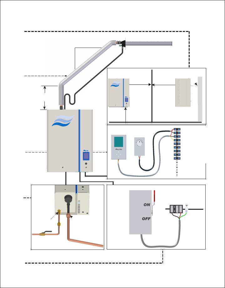
Typical Humidifier Installation |
|
|
|
|
Mounting |
|
|
|
|
Pg 13 |
|
|
|
|
|
1ft (30 cm) |
|
|
|
|
2 in. |
|
|
|
|
(5 cm) |
|
|
|
|
min. |
|
|
|
Steam |
0” (0 cm) |
|
Screws |
|
|
|
|
||
Distribution |
right |
|
|
|
clearance |
|
|
|
|
Pg 15 |
|
|
|
|
|
|
|
|
|
|
6” (15 cm) |
|
|
|
|
recommended |
|
|
|
|
1 ft (30 cm) |
|
|
|
|
min. |
|
|
|
|
|
|
|
1 – 24 VAC |
|
|
|
1- 24 VAC |
|
|
|
|
2-2Security– SecurityLoopLoop |
|
|
|
|
3-3Common– Common |
|
|
|
|
4-4Channel– Channel1 1 |
|
|
|
|
5-5Channel– Channel2 2 |
|
Controls |
|
|
6-65–VDC10 VDC |
|
|
|
|
7- Ground |
|
Pg 22 |
|
|
|
7 – Ground |
|
|
8- Blower Pack |
||
|
|
|
|
8 – Blower Pack |
|
|
|
9- Blower Pack |
|
|
|
E |
|
9 – Blower Pack |
|
|
N |
|
|
|
|
X |
|
|
|
|
H |
|
|
|
|
T |
|
|
|
|
- |
|
|
|
|
E |
|
|
|
|
E |
|
|
|
|
R |
|
|
|
|
L |
|
|
|
|
N |
|
|
|
|
|
|
|
|
|
A |
|
|
|
|
L |
|
|
Plumbing |
|
|
|
Ground |
Pg 14 |
Dedicated |
L1 L2 L3 |
||
|
Circuit |
|
|
NH-EL |
|
Breaker or |
|
|
|
|
|
|
EXTERNAL |
|
|
Disconnect |
|
|
|
|
|
|
|
|
|
½ in NPT |
|
|
|
|
Air Gap |
|
|
|
|
Cold potable water |
|
|
|
|
150-1200 microsiemens |
|
|
|
|
30-80 psig |
|
|
|
Electrical |
|
|
|
|
Pg 21 |
|
|
|
|
|
Figure 4: Typical Humidifier Installation |
|
|
|
|
|
Installation | 10 |
||
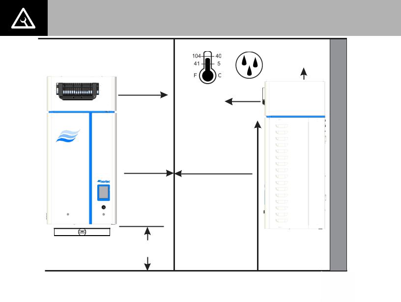
Location
Mount on a suitable wall or vertical surface. Do not sit the unit on the floor to allow clearances required for plumbing and electrical connections.
Clearance dimensions shown are for reference only and are the minimum required for maintenance of the humidifier. Consult local and national codes before final location and installation. NORTEC does not accept responsibility for installation code violations.
Install only in areas with ambient temperature 41-104 °F (5 – 40 °C) relative humidity 5 - 95% (non condensing).
When possible install the humidifier below the steam distributor. Take care to provide proper steam line routing and proper condensate traps.
DO NOT locate the humidifier any further than absolutely necessary from the steam distributor location. Net output will be reduced as a result of heat loss through the steam line.
When possible, mount the NH-EL humidifier at a height convenient for servicing.
Note: Do not mount on hot surfaces, where freezing can occur, vibrating surface, or floor.
|
|
(See Table for |
|
|
Blowerpack |
|
|
clearances) |
|
(See Table for |
|
|
Blowerpack |
5-95% |
|
clearances) |
|
|
|
|
|
|
(See Table for |
|
|
Blowerpack |
|
|
clearances) |
|
6 in. |
36 in. (91.5 cm) |
|
Min. Front Clearance |
|
|
(15 cm) |
|
|
Recommended |
|
|
Side |
|
|
Clearance |
|
|
|
If Blowerpack is used, |
|
|
mount so that the steam |
|
|
outlet is at least |
|
|
96 in. (244 cm) |
Mount Humidifier |
|
above ground level. |
24 in.(61 cm) |
|
|
Level |
|
|
Min Height |
|
|
|
|
Figure 5: Mounting Location / Clearance
11 | Installation

Table 5: Clearances for Blower Packs on Low Speed*
|
|
|
Minimum |
|
Min. Frontal |
|
Min. Overhead |
|
|
|
|
|
|
|
|
|
|
|
|
|
|
|
|
|
|||
|
|
|
|
|
|
|
|
|
|
|
|||
|
Humidifier |
|
No. of |
|
|
|
|
Min. Left side |
|
Min. Right side |
|
||
|
|
|
|
|
|||||||||
|
|
|
Clearance |
|
Clearance |
|
|
|
|
||||
|
Capacity |
|
Blower |
|
|
|
|
Clearance |
|
Clearance |
|
||
|
|
|
Inches (cm) |
|
Inches (cm) |
|
|
|
|
||||
|
lbs/hr (kg/hr) |
|
Packs |
|
|
|
|
Inches (cm) |
|
Inches (cm) |
|
||
|
|
|
|
|
|
|
|
|
|
||||
|
|
|
|
|
|
|
|
|
|
|
|
|
|
|
|
|
|
|
|
|
|
|
|
|
|
|
|
30 (13.6) |
|
|
1 |
|
|
132 (336) |
|
|
12(31) |
|
12 (31) |
|
12 (31) |
|
||||||
100 (45.4) |
|
|
1 |
|
|
|
Not |
|
|
Not |
|
Not |
|
Not |
||||||
|
|
|
|
|
recommended |
|
|
recommended |
|
recommended |
|
recommended |
||||||||
|
|
|
|
|
|
|
|
|
|
|
|
|
||||||||
|
|
|
|
|
|
|
|
|
Table 6: Clearances for Blower Packs on High Speed* |
|||||||||||
|
|
|
|
|
|
|
|
|
|
|
|
|
|
|
|
|
|
|
|
|
|
|
|
|
|
Minimum |
|
|
|
Min. Frontal |
|
|
|
Min. Overhead |
|
|
|
|
|
|
|
|
|
|
|
|
|
|
|
|
|
|
|
|
|
|
|
|
|
|||
|
Humidifier |
|
|
|
No. of |
|
|
|
|
|
|
|
|
Min. Left side |
|
|
Min. Right side |
|
||
|
|
|
|
|
|
|
Clearance |
|
|
|
Clearance |
|
|
|
|
|
||||
|
Capacity |
|
|
|
Blower |
|
|
|
|
|
|
|
|
Clearance |
|
|
Clearance |
|
||
|
|
|
|
|
|
|
Inches (cm) |
|
|
|
Inches (cm) |
|
|
|
|
|
||||
|
lbs/hr (kg/hr) |
|
|
|
Packs |
|
|
|
|
|
|
|
|
Inches (cm) |
|
|
Inches (cm) |
|
||
|
|
|
|
|
|
|
|
|
|
|
|
|
|
|
|
|
||||
|
|
|
|
|
|
|
|
|
|
|
|
|
|
|
|
|
|
|
|
|
|
|
|
|
|
|
|
|
|
|
|
|
|
|
|
|
|
|
|
|
|
30 (13.6) |
|
|
1 |
|
|
120 (305) |
|
|
12(31) |
|
12 (31) |
|
12 (31) |
|
||||||
100 (45.4) |
|
|
1 |
|
|
248 (630) |
|
|
36 (91) |
|
30 (76) |
|
30 (76) |
|
||||||
*NOTES:
Nominal Conditions 72˚F (22.2˚C), 43% RH.
Low speed not recommended for 100 lbs/hr humidifier. Consult factory for recommendations. Blower Pack should not be installed near cold surfaces or where dew point may be reached. Higher humidity or lower room temperature may result in longer absorption distances.
Installation | 12
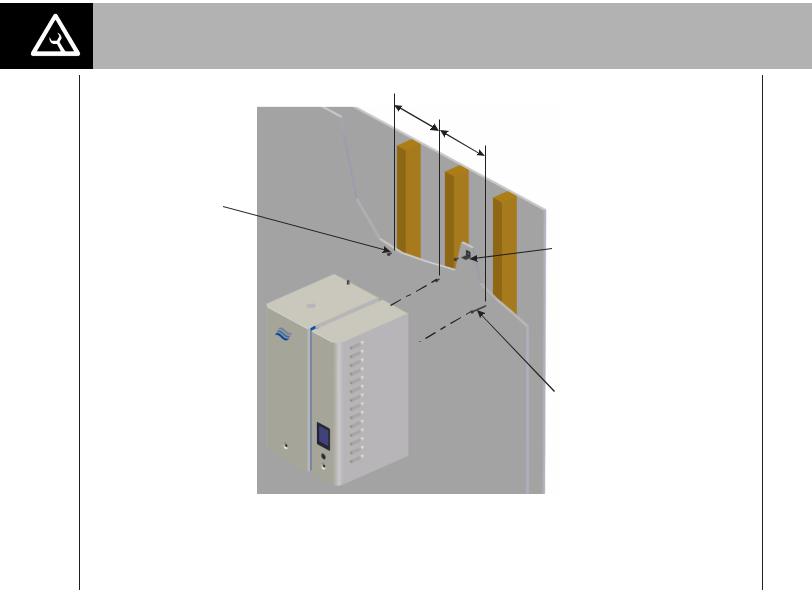
Mounting with Keyholes
1The NH-EL Series humidifier is wall mounted using keyholes located on the back of the unit cabinetry.
2Use #12 x 3 in. (7.5 cm) screws mounted into 2x4 studs or better. Two screws are needed for a single unit (NH-EL 010 to 100). Three screws are needed for a double unit (NH-EL 150 to 200).
3Keyholes are spaced 16 in. (40.6 cm) apart center to center for large units and 11.9 in. (27.2 cm) apart for small units. Insert screws into the studs until there is 1/4 in. of screw exposed. Be sure the screws are level to each other.
4Raise the unit and place the screws through the keyholes. Make sure the unit is level, then tighten the screws to secure the unit in place.
5Place “L” Shaped brackets on top of the unit, with holes inline with the studs. Using the appropriate sized wood screw, fasten the “L” brackets to the studs, securing the unit from any upward motion. See Figure 6: Mounting with Keyholes.
Note: Use screws longer than 3” (7.5 cm) if drywall or other spacer is present.
SPACE
B
A
Insert screws so that 1/4 in. (6 mm) exposed, hang unit, tighten
screws.
Install “L” bracket after hanging humidifier
#12 x 3 in. (7.5 cm) Wood Screws
|
|
|
|
Unit Size |
Screws |
Dim A in (cm). |
Dim B in. (Cm) |
5-30 |
2 |
11.9 (30.2) |
- |
|
|
|
|
50-100 |
2 |
16 (40.6) |
- |
150-200 |
3 |
16 (40.6) |
16 (40.6) |
|
|
|
|
SPACE
Figure 6: Mounting with Keyholes
13 | Installation
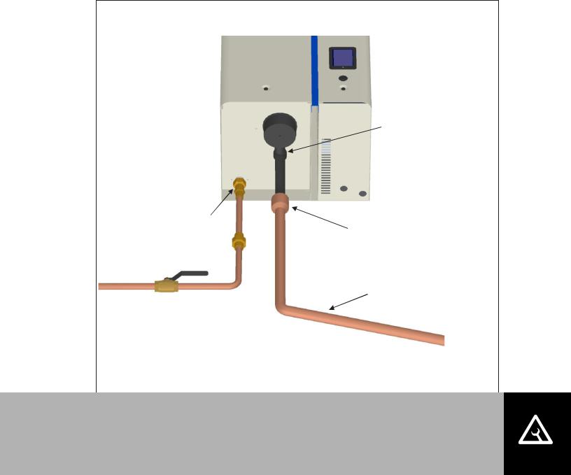
Plumbing
1/2 in. NPT Use union to connect supply pipe to unit.
Always install a water shut-off valve.
*Pipe and water shut-off valve not supplied by NORTEC.
1.2 in. (30 mm). OD un-threaded outlet with factory supplied bent hose and clamp.
Air gap required.
2 1/2 in. to 7/8 in. copper reducer is ideal.
(NORTEC option P/N 2522172) Hose must not touch
the bottom of the funnel.
Min. 7/8 in. OD drain line. Keep as short as possible. Slope down to floor
drain or main drain. Increase size if combining
multiple drains as in double unit.
Figure 7: Water Supply and Drain Connection
Note:
Drain Water is very hot, do not drain to public sink
Supply cold potable water (not Reverse Osmosis or Demineralized). Conductivity: 150–750 microsiemens and pressure: 30-80 PSIG.
Use material suitable for 212°F (100°C) for drain and condensate lines.
All water supply and drain line connections should be installed in accordance with local plumbing codes.
Supply water should at 30 to 80 PSIG and be between 150-750 microsiemens (Hardness 0-12 GPG). For 750-1200 microsiemens, please consult factory.
Install water shut off valve and union before humidifier to facilitate servicing.
The drain line should not end in a sink used frequently by personnel, or where plumbing codes prohibit. Route to a floor drain or equivalent for safety reasons.
Ensure drain line is adequately sized to provide free and easy draining and that an air gap is installed as shown. A restricted drain can cause cylinder water to over concentrate, resulting in poor operation or result in water backing up at the air gap.
Installation | 14
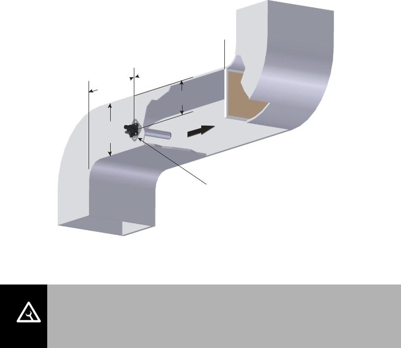
Steam Distributor
Steam generated by the NH-EL may be distributed directly into a space with a built on or remote blower pack, or into an air handling system using either Nortec steam distributors or
Nortec’s SAMe steam distribution manifold.
Whichever method is used, the steam distributor should be installed as close as possible to the humidifier. Short steam distribution lines minimize condensate losses and the possibility of generating back pressure in the steam distribution line.
Figure 8: Distributor Location in Duct provides common guidelines for locating a steam distributor in a duct.
Calculated absorption  distance to any obstruction
or 8-10 ft (2.4 - 3 m)  if unknown
2 x duct
height min.
2/3 Duct height
12 in.
(30 cm) min.
Mount distributor to side of duct
Figure 8: Distributor Location in Duct
Note:
Install the NH-EL as close as possible to whatever steam distributor is used.
Refer to distributor, SAMe, or remote blower pack installation manuals for detailed installation instructions.
15 | Installation

Steam Lines and Condensate Return Instructions
The following instructions must be followed for installation of steam lines for ASD, BSD, CSD, SAM-e, and remote blower packs. Failure to use material recommended in
Table 7, exceeding maximum recommended length in Table 7, or failure to follow any other steam line installation instructions will result in improper operation and could void the warranty.
Danger:
The NH-EL is an atmospheric humidifier that will only operate properly when its steam distribution system is installed so that it provides no significant backpressure.
Installing the NH-EL in such a way that backpressure can develop during operation could result in serious injury or damage to property.
Table 7: Recommended Steam Line Material*, Maximum Length, Losses
|
NH-EL |
Maximum Steam |
MED-L |
Stainless |
Possible Steam Losses |
|||||
|
||||||||||
|
|
|
|
|
|
|
|
|
|
|
|
Model |
Line Length |
Copper |
Steel |
(based on 1” insulated copper pipe) |
|||||
|
|
ft |
|
(m) |
Tube |
Tube |
lb/hr/ft |
|
(kg/hr/m) |
|
|
|
|
|
|||||||
5 |
7 |
(2) |
|
|
|
|
|
|||
10 |
12 |
(3.5) |
3/4 |
0.875 X 0.049W |
0.06 |
(0.09) |
||||
20 |
17 |
(5) |
||||||||
|
|
|
|
|
||||||
30 |
22 |
(6.5) |
|
|
|
|
|
|||
50 |
43 |
(13) |
|
|
|
|
|
|||
75/150** |
47 |
(14) |
1 1/2 |
1.75 X 0.065W |
0.11 |
(0.16) |
||||
100/200** |
50 |
(15) |
|
|
|
|
|
|||
|
|
|
|
Oversized Steam Line (Use for longer steam runs)*** |
|
|
||||
5 |
14 |
(4) |
|
|
|
|
|
|||
10 |
24 |
(7) |
1 |
1.125 X 0.049W |
0.06 |
(0.09) |
||||
20 |
34 |
(10) |
||||||||
|
|
|
|
|
||||||
30 |
44 |
(13) |
|
|
|
|
|
|||
50 |
86 |
(26) |
|
|
|
|
|
|||
75/150** |
94 |
(28) |
2 |
2.0 X 0.065W |
0.11 |
(0.16) |
||||
100/200** |
100 |
(30) |
|
|
|
|
|
|||
|
|
|
|
|
Nortec Steam Hose |
|
|
|
||
5-30 |
10 |
(3) |
Pt No 1328810 (7/8”) |
0.1 |
(0.15) |
|||||
50-200** |
10 |
(3) |
Pt No. 1328820 (1 3/4”) |
0.15 |
(0.22) |
|||||
Note: * The use of steam line other than copper, stainless steel tube or Nortec supplied steam line will void the warranty and may adversely affect the operation of the humidifier.
**Use one steam line per cylinder for NH-EL 150-200 humidifiers. Do not combine lines except at distributor using a Nortec adapter designed for that purpose and only if humidifiers operate in parallel.
***These diameters require a reducer at humidifier and steam distributor connection.
Installation | 16
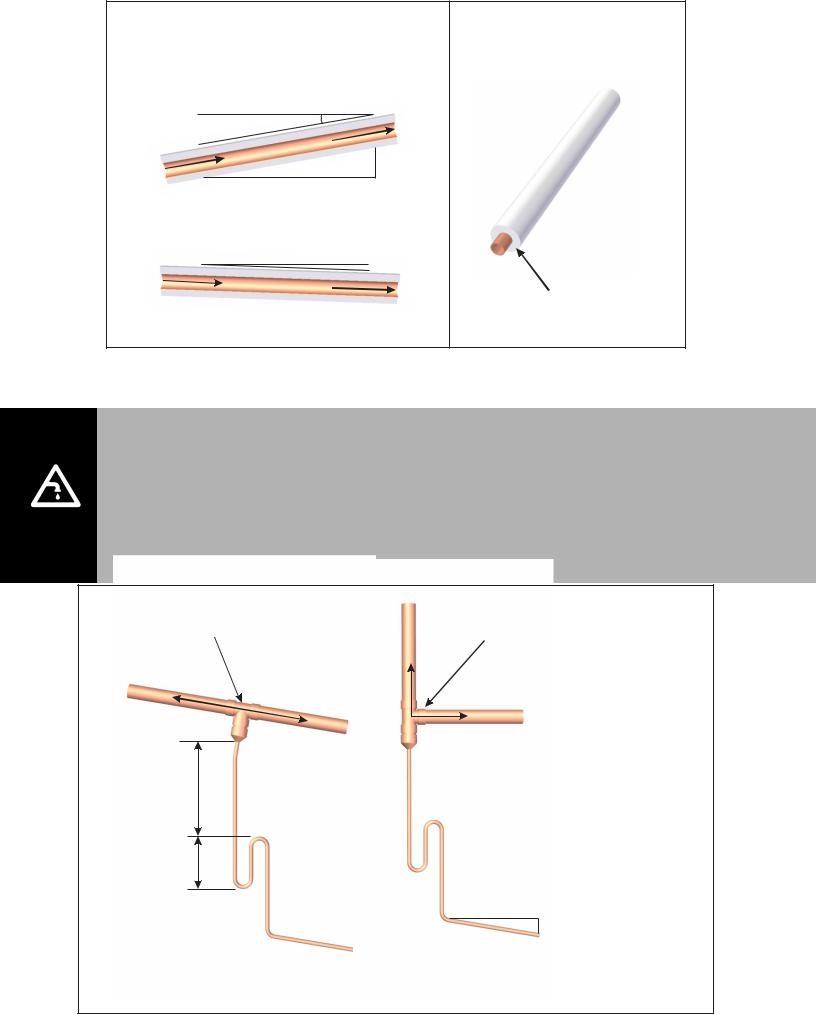
Use Appropriate Slope |
Insulate Pipe |
Minimal Slope (up)
10 Degrees
|
|
|
|
|
|
n |
|
|
|
|
|
io |
|
|
|
|
|
ct |
|
|
|
|
|
re |
|
|
|
|
|
|
i |
|
|
|
|
|
m D |
|
|
|
|
|
ea |
|
|
|
|
|
t |
|
|
|
|
|
|
S |
|
|
|
|
|
|
1 ft (30 cm)
2 in. (5 cm)
|
|
Minimal Slope (down) |
|
|
|
|
2 Degrees |
|
|
Stea |
|
|
|
m Direction |
|
0.5 in. |
|
|
1 in. (2.5 cm) pipe |
|
1ft (30 cm) |
||
(12 mm) |
insulation |
||
|
|
||
Figure 9: Steam Line Slope and Insulation
Trap condensate
Trap at all low points and recommended intervals using full size ‘T’ for traps.
Condensate should not be routed to a sink used frequently by personnel. Route to a floor drain or equivalent. Condensate normally cools in traps but is still hot. A SAMe or larger steam line generates more condensate and water may not cool in the trap. A drain water cooler option may be installed if required by code.
Route condensate to floor drain or equivalent in multi-unit to single SAM-e installation.
Tee is same size as steam line
12 in. (30 cm) min drop to top of ‘P’ Trap
P Trap min 6 in. (15 cm) or duct static
pressure + 2 in whichever is greater
Use a full size tee, not a 90 degree elbow for vertical
to horizontal transitions.
‘P’ Traps Use:
-NORTEC 0.375 in condensate hose
-1/4 in Med-L copper tubing, or
-0.375 in stainless steel tubing
1 ft (30 cm)
0.25 in
(0.6 cm)
Condensate drains must be sloped down.
17 | Installation
|
|
|
|
|
|
|
|
Hose cuff |
|
|
|
|
|
|
|
|
|
with clamps |
|
|
|
|
|
|
|
|
1 ft (30 cm) |
||
2 in. (5 cm) |
|
Condensate line |
|||||||
|
|||||||||
|
|
|
|
|
min. |
|
|||
|
|
|
|
|
|
Route to fill cup or drain . |
|||
|
|
|
|
|
|
|
|
||
|
|
|
|
|
|
|
|
Insulated copper |
|
|
|
|
|
|
|
|
|
||
|
|
|
|
|
|
|
|
steam line. Support |
|
|
|
|
|
|
|
|
|
||
1 ft (30 cm) |
|
so weight is not on |
|||||||
|
cylinder. |
||||||||
min. before |
|
||||||||
‘P’ Trap |
|||||||||
any bend |
|||||||||
|
|
||||||||
|
|
|
|
|
|
|
|
Use steam hose and clamps |
|
|
|
|
|
|
|
|
|
||
|
|
|
|
|
|
|
|
between cylinder and steam line. |
|
Figure 11: Typical Steam Line Installation
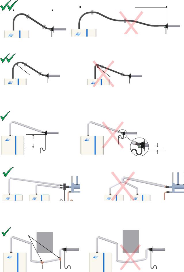
Steam Line Rules
The following 10 points provide rules for installing steam lines connecting the NH-EL humidifier to ASD, BSD, CSD, SAMe and remote blower packs. In addition to these rules never use unapproved material for steam lines.
1. Allow minimum of 12 in. (30 cm) before first bend in steam line.
Never
Best
< 1 ft
(30 cm)
1 ft (30 cm) min.
2. Slope the steam lines.
Best |
Good |
Never |
|
||
|
1 ft (30 cm) |
|
|
min 2 in. |
|
1 ft (30 cm) |
(5 cm) |
|
|
|
|
|
min 0.5 in. |
|
|
(12 mm) |
|
Installation | 18
3. Use steam hose only for short distances.
Best |
|
|
Never |
|
|||||
|
|
> 10 ft (1.5 m) |
|
||||||
|
|
|
|||||||
|
|
||||||||
|
< 5 ft (1.5 m) |
|
|
|
|
|
|
|
|
|
|
|
|
|
|
|
|
||
|
|
|
|
|
|
|
|
|
|
|
|
|
|
|
|
|
|
|
|
Note: 1) Always support hose. 2) Do not exceed 10 ft (3 m) hose length
4. For steam hose maintain minimum 12 in. (30 cm) bend radius.
Best |
|
Never |
|
|
|
|
|
|
12 in. |
< |
12 in. |
|
(30 cm) |
||
|
(3 |
0 cm) |
|
|
min. Radius |
||
|
Radius |
||
|
|
||
5.Install traps on condensate lines at least 12 in. (30 cm) below connection.
Good |
Never |
min. 12 in. (30 cm)
< 12 in. (30 cm)
6. Only combine steam lines at steam distributor with Nortec adapter.
Good |
Never |
Notes: 1. Units must operate in parallel.
2.Also for double units (cylinders must operate in parallel).
7.Install condensate traps at low points and horizontal to vertical transitions.
Good |
Condensate |
Never |
|
Traps |
|||
|
19 | Installation
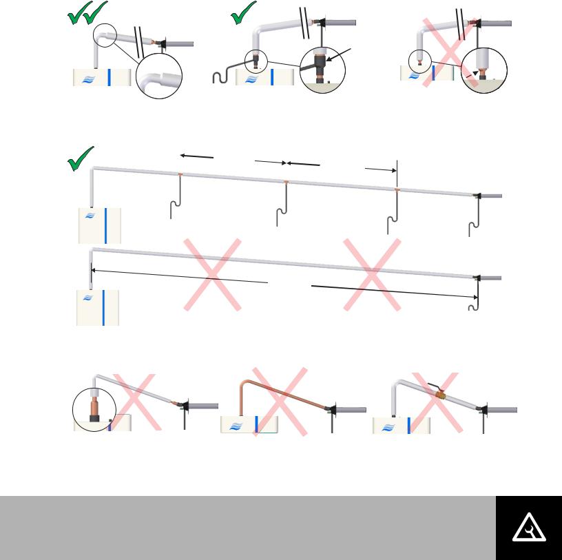
8. Increase diameter either on down slope or install condensate trap.
Best Sloping Down |
Good |
Never |
Nortec
Condensate
Trap
Increase =
Condensate
Blockage
9. Install condensate traps if steam line > 15 ft (4.5 m).
Good |
max. 15 ft |
|
max. 15 ft |
|
|||
(4.5 m) |
|
||
|
|
||
|
|
|
(4.5 m) |
|
|
||
|
|
|
|
Never
> 15 ft (4.5 m)
10. In addition never:
|
|
|
Never |
|
|
|
Never |
Never |
|
|
|
|
|
|
|
|
|
|
|
Reduce Steam Line Size |
Install Copper or SST without Insulation Install a valve or other obstruction |
After Installation Always:
Purge steam lines to remove any contaminants and installation materials
Ensure all condensate lines / traps flow.
Installation | 20
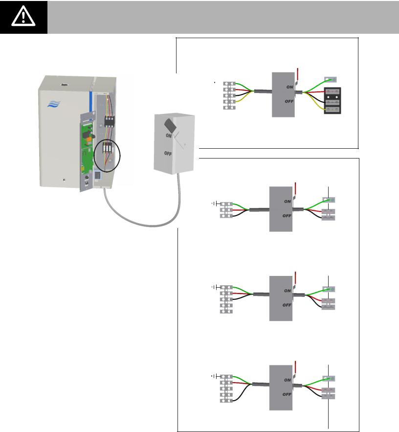
Electrical
Caution: Wiring to be performed by a licensed electrician.
Note:
1Optional internal fuses are not a substitute for external fuses.
2Dedicated external fused disconnect must be installed. Fusing must not exceed max circuit protection as indicated on the specification label.
3Ensure that adequate power is available to carry full humidifier amp draw as indicated on the specification label.
4All wiring to be in accordance with national and local electrical codes.
Three Phase NH-EL
Three Phase Supply |
|
|
|||||
Ground |
|
|
|
|
|
|
Ground |
|
|
|
|
|
|
||
L1 |
|
L1 |
|||||
L2 |
|
||||||
|
|
||||||
L3 |
|
L2 |
|||||
Neutral |
|
||||||
|
L3 |
||||||
|
|
|
|
|
|
|
|
|
|
|
|
|
|
|
|
|
|
|
|
|
Dedicated |
E |
I |
|
|
|
|
|
X |
N |
|
|
|
|
|
|
Circuit Breaker |
||
|
|
|
|
|
T |
T |
|
|
|
|
|
|
or |
||
|
|
|
|
|
|
|
|
|
|
|
|
|
Fused Disconect |
|
|
|
|
|
|
|
|
|
|
Single Phase NH-EL
Single Phase Supply
Ground
L1
L2
Three Phase Supply
(Note: Load will be unbalanced)
Ground
L1
L2
L3
Neutral
Three Phase Supply
(Note: Load will be unbalanced)
Ground
L1
L2
L3
Neutral
Ground .
L1
L2
E |
I |
X |
N |
T |
T |
|
|
Ground
L1
L2
E |
I |
X |
N |
T |
T |
|
|
Ground
L1
Neutral
E |
I |
X |
N |
T |
T |
.
Figure 12: Primary Power Connection
21 | Installation
External Controls
Control Wiring
The following information is relevant to all controls, factory supplied or otherwise. For wiring use a minimum of 18 AWG and keep as short as possible. The NH-EL humidifier can be operated with two modulating inputs. Signal types must be the same (both demand or both transducer). The NH-EL can also be operated as On/Off. See NH-EL Humidifier Configuration on page 54 for configuration.
Caution: Failure to wire the humidifier in accordance with the wiring instructions could cause permanent damage. Such errors will void the warranty.
Control Location
 10 ft min.
4 |
1 |
2 |
3 |
Out |
Air |
Duct High |
Humidity |
door |
Proving |
Limit |
Control |
temp. |
Switch |
|
(return air |
sensor. |
|
|
duct or |
location
representative of the room)
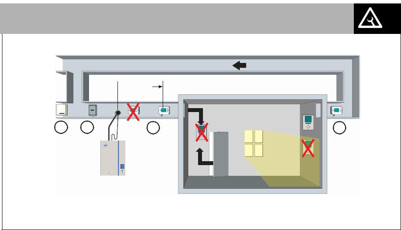
Figure 13: Control Location (Duct Humidification)
Duct Humidification
1 |
Air Proving Switch |
|
Locate so that it can sense air flow or lack of it. |
2 |
Duct High Limit |
|
NH-EL can be modulating, On/Off, or a humidity sensor. |
|
Locate at least 10 feet from steam distributor or far enough that under normal conditions |
|
steam is fully absorbed. |
3 |
Humidity Control |
|
NH-EL can be Modulating, On/Off, or a Humidity Sensor. |
|
Can be located either in return air duct (preferred) or in room being humidified. |
|
Mount in area representative of room humidity (draft, doorways, sunlight, or overhang such |
|
as a shelf can affect reading). Avoid placing near discharge diffuser of humidified air. |
4 |
Outdoor Temperature Sensor |
Mount in area representing outdoor air temperature (makeup air duct, outside).
Installation | 22
Note: Regardless of selecting on/off or modulating control method, Nortec humidifiers must have a closed circuit across its security loop control terminal to operate. Nortec highly recommends the use of a high limit humidistat and an air proving switch in series for this function.
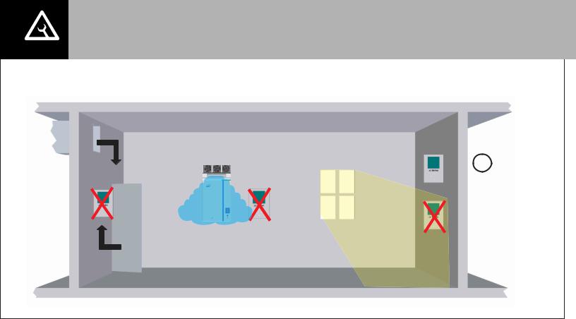
Space Humidification
1
Humidity
Control
(in location representative of the space)
|
Figure 14: Control Location (Space Humidification) |
1 |
Humidity Control |
|
NH-EL can be modulating, On/Off, or a humidity transducer. |
|
Locate in room being humidified but not in discharge zone of blower pack(s). |
|
Mount on indoor wall in area representative of room humidity (draft, doorways, sunlight, or |
|
overhang such as a shelf can affect reading). |
2 |
High Limit Humidistat (not shown) |
Install a high limit On/Off humidistat in area representative of room humidity.
3 Outdoor Temperature Sensor (not shown)
Mount outside in area representing air temperature.
23 | Installation
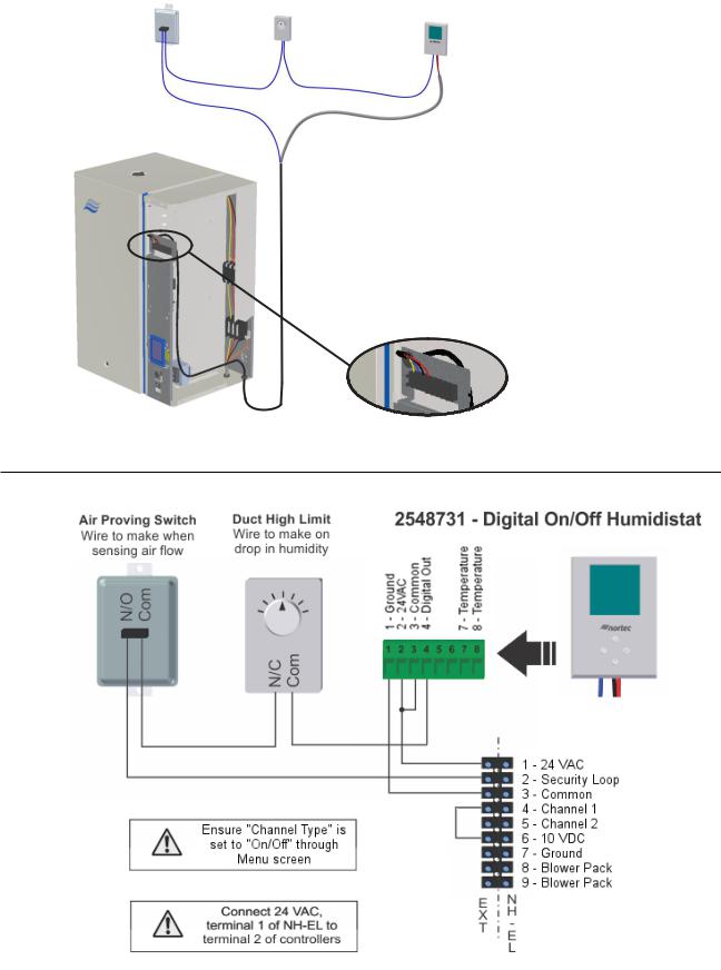
On/Off Control Wiring
Air Proving |
Duct High |
|
Switch |
||
Limit |
||
|
2548731 - Digital
On/Off Humidistat
Note: 1 Humidifier will run when circuit between terminal 1 and 2 on humidifier is closed.
2Terminal 1 is 24 VAC Hot, turn unit off to avoid shorting while wiring.
3Digital Humidistat requires 24 VAC power from terminals 1 and 3 of humidifier.
42520273 - Digital On/Off Duct Humidistat can also be used for duct high limit. Wire in series to 3 - Common and 4 - Digital Out of the humidistat.
Humidifier Terminal Strip
Figure 15: On/Off Controls
Common |
24 VAC Digital In Digital Out Fan Activation Fan Activation Temperature |
Temperature |
1 – 2 – 3 – 4 – 5 – 6 – 7 – 8 – |
||
|
|
|
Figure 16: Digital On/Off Humidistat
Installation | 24
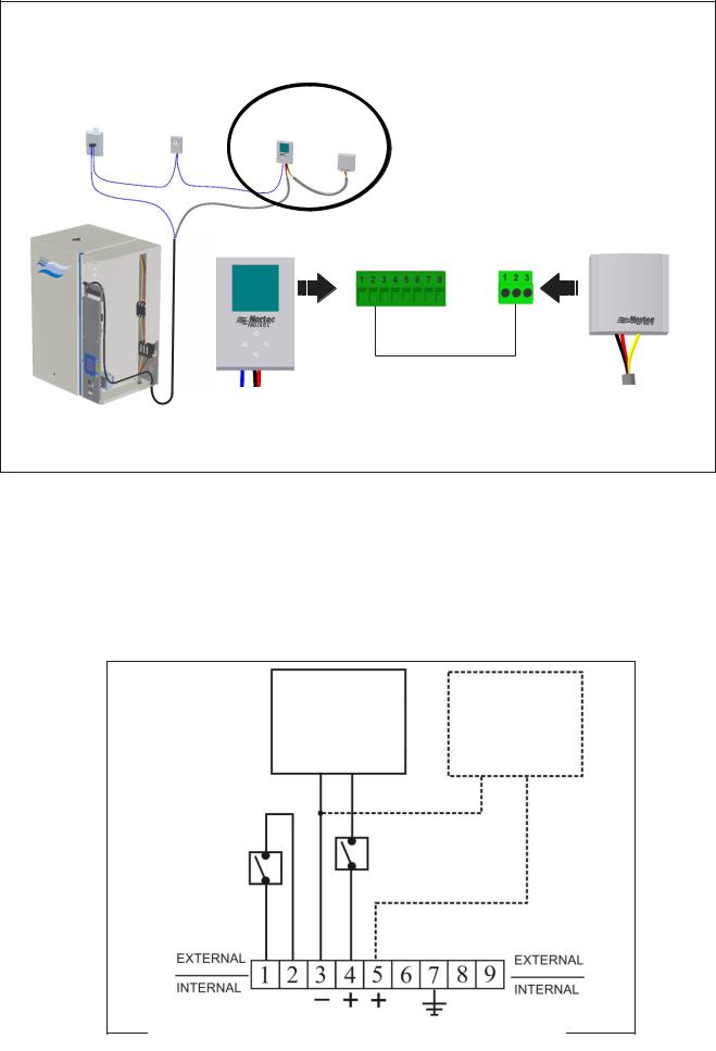
|
|
|
|
|
2520273 - Digital On/Off Duct Humidistat Package |
||||||||||||||
|
|
|
|
|
|
|
|
|
|
Wire remote sensor to digital display as shown below, |
|||||||||
|
Air Proving |
Duct High |
Digital On/Off |
wire digital display to humidifier as shown above. |
|||||||||||||||
|
|
|
|
|
|
|
|
|
|
||||||||||
|
Switch |
|
|
|
|
|
|
|
|
|
|||||||||
|
Limit |
Humidistat |
|
|
|
|
|
|
|
|
|
||||||||
|
|
|
|
|
|
|
|
|
|
|
|||||||||
|
|
|
|
|
|
Duct Sensor |
|
|
|
|
|
|
|
|
|
||||
|
|
|
|
|
|
|
|
|
|
|
|
|
|
|
|
|
|
|
|
|
|
|
|
|
|
|
|
|
|
|
|
|
|
|
|
|
|
|
|
|
|
|
|
|
|
|
|
|
|
|
|
||||||||
|
|
|
|
|
|
|
|
|
Ground – Common 24 VAC – 24 VAC |
Analog In – Analog In |
|
Common 24 VAC Analog Out |
|||||||
|
|
|
|
|
1 2 |
7 |
|
- - - |
|
|
|
||||||||
|
|
|
|
- - |
- |
|
|
|
|
|
|
|
|||||||
|
|
|
|
1 2 |
7 |
|
|
|
|
|
|
|
|||||||
|
|
|
|
|
|
|
|
|
|
|
|
|
|
|
|
|
|
|
|
|
|
|
|
|
|
|
|
|
|
|
|
|
|
|
|
|
|
|
|
|
|
|
|
|
|
|
|
|
|
|
|
|
|
|
|
|
|
|
|
|
|
|
|
|
|
|
|
|
|
|
|
|
|
|
|
|
|
|
|
|
|
|
|
|
|
|
|
|
|
|
|
|
|
|
|
|
|
|
|
|
|
|
|
|
|
|
|
|
|
|
|
|
|
|
|
|
|
|
|
|
|
|
|
|
|
|
|
|
|
|
|
|
|
|
|
|
|
|
|
Figure 17: Duct Sensor Wiring
Keep Warm Wiring
For the keep warm feature to work the security loop between terminal 1 and 2 on the low voltage terminal strip must be closed. To accomplish this:
1Install an On/Off high limit humidistat between terminal 1 and 2.
2Install any other On/Off controls in series with the control signal connected to terminal 4 (Channel 1 control signal).
3If desired a modulating high limit humidistat can also be installed and connected to terminal 5 (Channel 2 control signal).
|
Humidity Controller |
Optional Modulating |
|
Humidity Controller |
|
|
Channel 1 |
|
|
Channel 2 |
|
The security loop must |
|
|
|
|
|
be closed for keep warm |
|
|
to operate when the |
|
|
humidifier is in standby. |
|
|
Install an On/Off high |
|
|
limit humidistat between |
Other On/Off |
|
terminal 1 and 2. |
|
|
Controls |
|
|
|
|
Figure 18: Keep Warm Wiring
25 | Installation
Modulating Control Wiring
Air Proving
Switch
High Limit Humidistat
Control Humidistat
Note: 1 Install On/Off controls or jumper between terminal 1 and 2 of humidifier in order to run.
2Terminal 1 is 24 VAC Hot, turn unit off to avoid shorting while wiring.
3High Limit Humidistat must be duct mounted. It can be On/Off or modulating.
4Control Humidistat can be mounted in space or in return air duct and can be On/Off or modulating.
Humidifier Terminal Strip
Figure 19: Modulating Controls
Common |
24 VAC |
|
Common |
24 VAC |
1 – |
2 – |
|
1 – |
2 – |
|
|
|
|
|
Analog Out -3
24 VAC – 2
Common – 1
Figure 20: Digital Modulating Humidistats
Installation | 26

|
|
|
|
|
|
|
2520261 - Digital Wall W/O Sensor |
|||
|
Air Proving |
Duct High |
|
|
|
|
|
+ |
|
|
|
|
|
|
|
|
|
|
|
||
|
Switch |
Limit |
2520261 - Digital |
1509858 - Wall |
1509858 - Wall Sensor |
|||||
|
|
|
Wall W/O Sensor |
|
|
|
|
|||
|
|
|
|
Sensor |
|
|
|
|
||
|
|
|
|
|
|
Wire wall sensor to digital display as shown |
||||
|
|
|
|
|
|
|
||||
|
|
|
|
|
|
|
below, wire digital display to humidifier as shown |
|||
|
|
|
|
|
|
|
for 1510142 - Digital Wall Humidistat. |
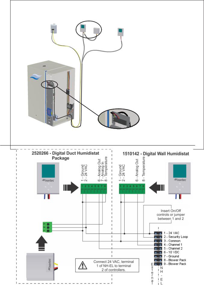
|||
|
|
|
|
|
Common 24 VAC |
Analog In |
Common 24 VAC |
Analog Out |
||
|
|
|
|
|
||||||
|
|
|
|
|
1 - 2 - |
7 - |
1 - 2 - |
6 - |
|
|
|
|
|
|
|
|
|
||||
|
|
|
|
|
|
|
|
|
|
|
|
|
|
|
|
|
|
|
|
|
|
2520261 - Digital |
|
1509858 - Wall |
Wall W/O Sensor |
|
Sensor |
Figure 21: Digital Wall Humidistat – Remote Wall Sensor
|
|
|
– Temperature – Temperature |
– Common – 24 VAC |
|
– Common – 24 VAC – Common – Digital Out |
|
1 2 |
|
1 2 3 4 |
7 8 |
|
|
|
|
Figure 22: Digital Wall Humidistat - On/Off High Limit Duct Humidistat
27 | Installation
 Loading...