

Page 1
SE
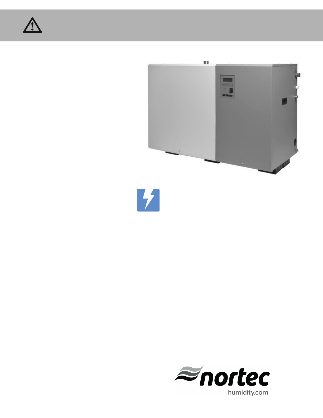
Important: Read and save these instructions. This guide to be left with equipment.
Series
Installation and
Operation Manual
Includes installation, operation,
maintenance, and troubleshooting
information for your indoor SETC B+
and SEP steam exchange humidifier
2552940-B | 28 APR 2011
Page 2

Thank you for choosing Nortec.
INSTALLATION DATE (MM/DD/YYYY)
MODEL #
SERIAL #
Proprietary Notice
This document and the information disclosed herein are proprietary data of NORTEC HUMIDITY LTD. Neither
this document nor the information contained herein shall be reproduced used, or disclosed to others without
the written authorization of NORTEC HUMIDITY LTD., except to the extent required for installation or
maintenance of recipient’s equipment. All references to the Nortec name should be taken as referring to
NORTEC HUMIDITY LTD.
Liability Notice
Nortec does not accept any liability for installations of humidity equipment installed by unqualified personnel or
the use of parts/components/equipment that are not authorized or approved by Nortec.
Copyright Notice
Copyright 2010, NORTEC HUMIDITY LTD. All rights reserved.
Page 3

Contents
1 Introduction
2 Receiving and Unpacking
3 Humidifier Components
5 SETC/P Models
6 Options and Accessories
9 Installation
10 Typical Humidifier Installation
11 Location
12 Mounting
14 Plumbing
15 Boiler Steam and Boiler
Condensate Return
17 Steam Lines and Condensate
Returns
43 Operation
44 SETC LED Status Lights
44 SEP LED Status Lights
45 How the Humidifier Works
49 SETC Humidifier Configuration
60 SEP Humidifier Configuration
63 Maintenance and
Servicing
64 Required Maintenance
65 Maintenance Schedule
69 Maintenance Shutdown and
Extended Shutdown
70 Maintenance Checklist
71 Troubleshooting
22 Electrical
23 External Controls
32 Options and Accessories
33 Start Up
34 Installation Check
35 SETC User Interface
36 Start Up Procedure
37 Status Screens
39 Nortec Digital Controls
41 Start Up Checklists
73 General Troubleshooting
76 SETC Warnings and Faults
82 SEP Faults
83 Wiring Diagrams
85 Spare Parts
96 Warranty
Page 4

CAUTION: Servicing
Disconnect main power before any servicing.
Shut off pressurized steam supply and ensure steam pressure is safely relieved
before any servicing of pressurized steam components.
The electrical compartment contains high voltage components and wiring. Access
should be limited to authorized personnel only.
During and following operation of the humidifier, the steam and components in
contact with the steam such as the tank, blower pack, steam lines, steam
distributors, and condensate lines can become hot and can burn if touched.
Walter Meier does not accept any liability for installations of humidity equipment
installed by unqualified personnel or the use of parts/components/equipment
that are not authorized or approved by Walter Meier.
CAUTION: Electrical
All electrical work should be done according to local electrical code.
Electrical connection to be performed by a licensed electrician.
CAUTION: Plumbing / Steam Lines
Plumbing to be performed by a licensed plumber.
Pressurized steam line installation to be performed by a qualified installer.
Drain water from humidifier can be very hot. Do not drain to public sink.
All plumbing and pressurized steam supply line work should be done according to
local plumbing code.
CAUTION: Installation
Do not mount on hot surfaces
Do not mount in area where freezing can occur
Do not mount on vibrating surface
The SETC/P produces steam at atmospheric pressure no devices which could
block steam output should be connected to the steam outlet.
Steam output lines must be installed so that no restriction can produce
backpressure in the humidifier.
Regardless of selecting On/Off or modulating control method, Nortec humidifiers
must have a closed circuit across its On/Off security loop control terminal to
operate. Nortec highly recommends the use of a high limit humidistat and an air
proving switch in series for this function.
Unit damage caused by water quality outside of the specified ranges is not
covered under warranty.
Introduction
1 | Introduction
Page 5
Note: A steam valve, actuator, and wye strainer are shipped along with the SETC/P
humidifier but in separate small boxes.
Receiving and Unpacking
1 Check packing slip to ensure ALL material has been delivered.
2 All material shortages are to be reported to Nortec within 48 hours from receipt of goods.
Nortec assumes no responsibility for any material shortages beyond this period.
3 Inspect shipment for damage and note damages on shipping waybill accordingly.
4 After unpacking, inspect equipment for damage and if damage is found, notify the shipper
promptly.
5 All Nortec products are shipped on an FOB factory basis. Any and all damage, breakage or
loss claims are to be made directly to the shipping company.
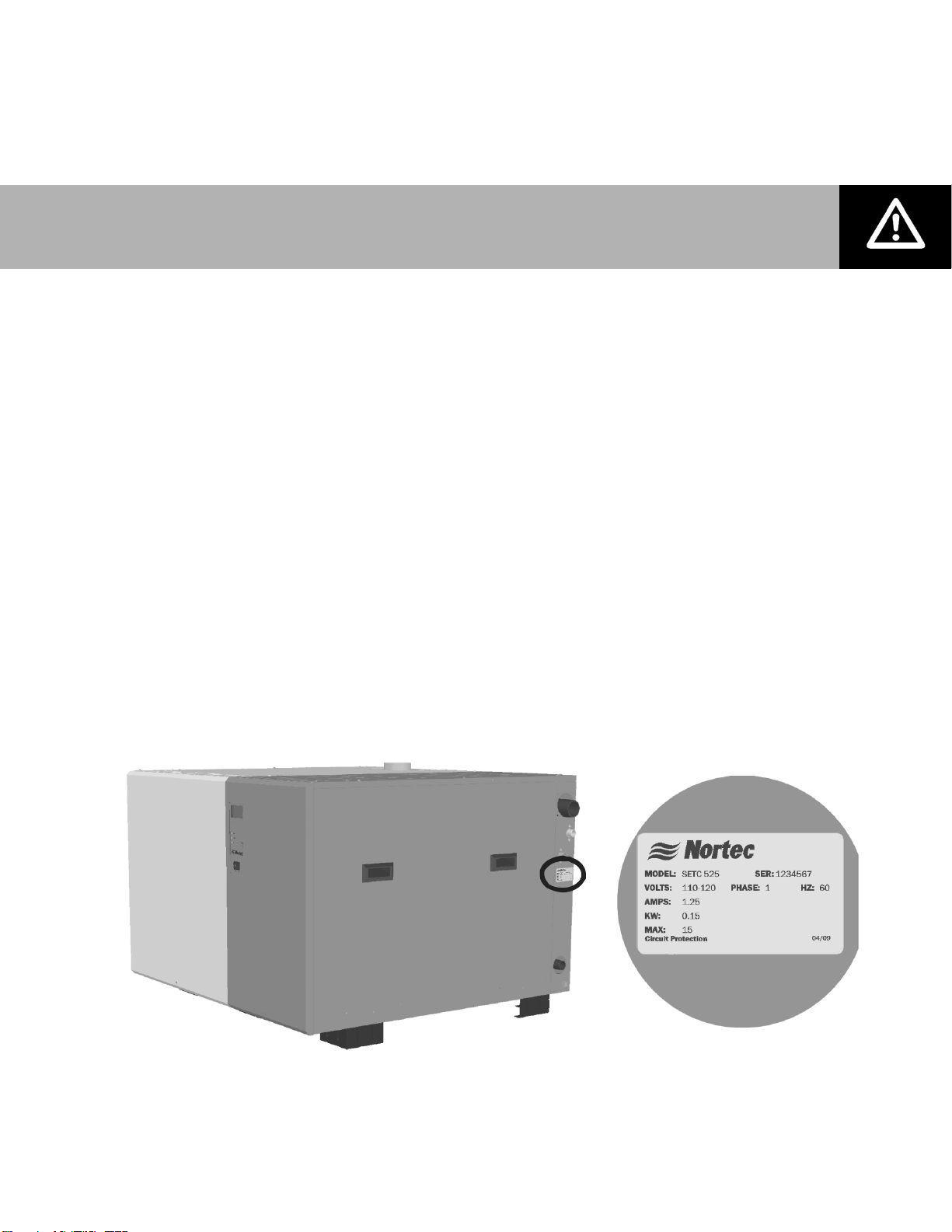
Before Installation
1 Ensure that available voltage and phase corresponds with humidifier voltage and phase as
indicated on humidifier’s specification label.
2 If steam supply is from a Medium or High Pressure boiler ensure supply steam line includes
a relief valve to prevent supply pressure from exceeding 15 psig.
3 Ensure means for returning boiler steam condensate to boiler at atmospheric pressure are
available.
4 Ensure sufficient clearances will be available as described in Location on page 11.
5 Ensure steam lines can be routed to distributor SAM-e manifold or blower pack as described
in Steam Lines and Condensate Returns on page 17.
6 Report any discrepancy immediately to the site engineer.
Figure 1: Specification Label Location
Introduction | 2
Page 6
Display and Keypad
Float Chamber
Control Terminal Strip
Remote Relay
Board
Driver Board
High Voltage
Terminal Block
Transformer
Base
Clean Out
Port
Tank
Total Controller
Steam Outlet
Fill Box
Vacuum Break
Steam Inlet
(Boiler Steam)
P Trap
Fill Valve
Drain Outlet
Condensate Drain
(Boiler Steam)
Auxiliary Drain
Outlet
Drain Pump
Mixing Box
Steam Trap
Heat
Exchangers
(Faceplate)
On/Off Switch
Heat
Exchanger
Gasket
Actuator
Wye Strainer
CV Valve
Manual Drain Switch
Humidifier Components
3 | Introduction
Figure 2: SETC Humidifier Components
Page 7

Component
Function of Component
Actuator
Opens and closes the CV valve in proportion to demand for steam.
Auxiliary Drain
Outlet
Drains water from tank in case of pump failure.
Base
Provides an integrated floor support for the humidifier.
Clean Out Port
Provides access to clean scale from the tank and heat exchanger.
Condensate Drain
Drains condensate formed from boiler steam in the heat exchanger(s)
Control Terminal
Strip
Terminal strip for connecting external controls and blower pack to
humidifier.
CV Valve
Controls the amount of steam allowed into the heat exchanger which in
turn controls the output of the humidifier.
Display and Keypad
User interface for configuring the humidifier.
Drain Outlet
Drain port used for draining water from the humidifier tank.
Drain Pump
Drains water from humidifier.
Driver Board
Provides input and output connections to humidifier components.
Fill Box
Provides an air gap for backflow prevention.
Fill Valve
Controls flow of water into humidifier.
Float Chamber
Measures water level in the humidifier tank.
Gasket
Seals heat exchanger face plate and clean out port cover to tank.
Heat Exchanger(s)
Exchanges energy from boiler steam to the tank water to produce steam
for humidification. The faceplate mounts the heat exchanger to the tank.
High Voltage
Terminal Block
Primary power connection from remote disconnect to humidifier.
Manual Drain Switch
Manually activates pump to drain water from the tank.
Mixing Box
Blends hot tank water with cool fill water to provide drain water cooling.
On/Off Switch
Turns power On/Off to humidifier controller. Note: Turn off humidifier
disconnect to shut off primary power to the humidifier.
P Trap
Prevents steam from flowing out the drain outlet.
Remote Relay
Board
Provides a terminal strip to dry contacts which open/close to indicate
the humidifier is on, humidifying, needs service, or is in a fault condition.
Steam Inlet
Connection for boiler steam, it is connected to the heat exchangers.
Steam Outlet
Connect to steam line with steam hose.
Steam Trap
Drains condensate from the heat exchanger without letting boiler steam
escape to drain.
Tank
Holds the water used to generate clean steam for humidification.
Total Controller
Controls all functions of the humidifier’s operation and provides user
interface for configuration of the humidifier.
Transformer
Steps primary voltage down to 24 VAC for the controller and internal
components such as the fill valve and drain valve.
Vacum Break
Prevents a siphon from occurring when the drain pump is stopped.
Wye Strainer
Protects CV valve and other system components from dirt and rust in the
piping system.
Description of Components
Table 1: Humidifier Components
Introduction | 4
Page 8
SETC50
SE 100-175
SE 250-375
SE 525-750
SE 1050
Note:
SE 750 has
2 steam outlets
SETC/P Models
The SETC with its Total Controller and state-of-the-art features and options is the most
advanced steam exchange humidifier available. The base model SEP provides steady and
reliable humidification using the same proven heat exchanger technology as the SETC. The
SETC/P is available in capacities ranging from 50 lb/hr (23 kg/hr) to 1050 lb/hr (475 kg/hr).
SETC/P humidifiers are packaged in five different cabinets depending on their capacity. Figure
3: SETC/P Modelsshows the configuration and relative size of the five different cabinets. Table
3 provides specifications for the SETC/P product line.
Figure 3: SETC/P Models
The SE 50, 100, 175, 250, and 375 all have a single heat exchanger. The SE 525 and 750
have two heat exchangers. The SE 1050 has three heat exchangers. All models have a single
pressurized steam inlet and condensate drain with internal manifold connecting separate heat
exchangers if they are present.
5 | Introduction
Page 9
Option / Accessory
Used For
Freeze Protection Package (SETC Only)
Emptying the tank in case of fault or power failure to prevent
freezing. (Factory installed)
Floor Stand
Supporting the humidifier 27 inches above the floor (height can be
reduced by cutting legs of floor stand). (field assembled)
Ceiling Mounting Kit (SE50 Only)
Providing a drain pan and support brackets for mounting an SE50
unit from the ceiling.
Steam Distributors
Adding steam into air ducts
Remote Blower Pack
Adding steam into a space remote from the humidifier.
SAM-e Steam Distribution Manifold
Adding steam into air ducts where short absorption is required.
Digital or Analog Control Humidistats
Controlling the output of the humidifier based on sensed RH (can
be mounted in the space being humidified or in the duct).
Digital RH Transducers
Communicating RH in a space or duct to the humidifier
Digital or Analog High Limit Humidistats
Preventing over humidification in a duct by shutting down or
throttling down the humidifier when duct RH gets high.
Air Proving Switches
Insuring humidification only occurs when air is moving in a duct.
Nortec LINKS 2 (SETC Only)
Connecting the humidifier to a building management interface.
hardware allows control of the humidifier via BACnet, Lonworks,
Johnson N2, or Modbus.
Nortec OnLine (SETC Only)
User and factory monitoring and configuration of the humidifier via
the internet.
Outdoor Model (SETC Only)
The outdoor model of the SETC provides a weatherproof enclosure that allows the SETC to be
installed on rooftops in moderately cool climates. Refer to the SETC installation manual that is
provided with the outdoor model to insure proper installation.
Options and Accessories
Nortec provides a complete line of options and accessories for every humidification application.
The following options and accessories are available and may have been delivered with your
SETC/P humidifier. Refer to the installation instructions that came with the accessories for their
proper installation and operation.
Table 2: Options and Accessories
Introduction | 6
Page 10
Model
SETC
Part No
SEP
Part No.
CV
Valve
CV Valve,
Steam
Inlet, Wye
Port (NPT)
Cond-
ensate
Port
(NPT)
Net/Full
Weight
lb (kg)
Required
fill line
flow
gal (l)
/min
Required
Drain
capacity
gal (l)
/min
Electrical
50
2552765
2520383
2.8
1/2
3/4
125/180
(57/82)
2.6 (10)
5.2 (20)
Voltage
110-120
Phase
1
Amps
1.25 A
Power
0.15 KW
Max
Disconnect
15 A
100
2550073
2525132
5.5
3/4
3/4
267/423
(121/192)
175
2550074
2525133
10 1 3/4
250
2550075
2525134
12 1 3/4
355/599
(161/272)
375
2550076
2525135
20
1 1/4
3/4
525
2550077
2553312
28
1 1/2
1
529/992
(240/450)
750
2550078
2553313
40 2 1
4.5 (17)
8 (29)
1050
2550080
2525139
65
2 1/2
1 1/4
703/1384
(318/628)
Model
*Supply
Steam
Pressure
(psig)
*Max Output
lb/hr (kg/hr)
Approximate
Boiler Steam
Consumption
lb/hr (kg/hr)
**Water
Consumption
gal (l) /hr
**Drain Volume
gal (l) /hr
50
5
13
(6)
15
(7)
2.3
(9)
0.8
(3)
10
32
(14)
36
(16)
5.7
(21)
1.9
(7)
15
50
(23)
58
(26)
9.0
(34)
3.0
(11)
100
5
26
(12)
30
(14)
4.7
(18)
1.6
(6)
10
63
(29)
72
(33)
11.3
(43)
3.8
(14)
15
100
(45)
115
(52)
18.0
(68)
6.0
(23)
175
5
46
(21)
52
(24)
8.2
(31)
2.7
(10)
10
110
(50)
127
(58)
19.8
(75)
6.6
(25)
15
175
(80)
201
(91)
31.5
(119)
10.5
(40)
250
5
65
(30)
75
(34)
11.7
(44)
3.9
(15)
10
158
(72)
181
(82)
28.3
(107)
9.4
(36)
15
250
(114)
288
(131)
44.9
(170)
15.0
(57)
375
5
98
(44)
112
(51)
17.5
(66)
5.8
(22)
10
236
(107)
272
(123)
42.5
(161)
14.2
(54)
15
375
(170)
431
(196)
67.4
(255)
22.5
(85)
525
5
137
(62)
157
(71)
24.5
(93)
8.2
(31)
10
331
(150)
380
(173)
59.5
(225)
19.8
(75)
15
525
(239)
604
(274)
94.4
(357)
31.5
(119)
750
5
195
(89)
224
(102)
35.1
(133)
11.7
(44)
10
473
(215)
543
(247)
84.9
(321)
28.3
(107)
15
750
(341)
863
(392)
134.8
(510)
44.9
(170)
1050
5
273
(124)
314
(143)
49.1
(186)
16.4
(62)
10
662
(301)
761
(346)
118.9
(450)
39.6
(150)
15
1050
(477)
1208
(549)
188.7
(714)
62.9
(238)
Table 3: SETC/P Specifications
Table 4: SETC/P Capacities and Water Consumption
7 | Introduction
* Supply steam pressure must be present at the CV valve to achieve rated output
** At maximum output , 25% blow down, and with drain water cooling activated.
Page 11
A
13.8 in.
35.1 cm
8.0 in.
20.3 cm
31.6 in.
80.3 cm
39.5 in.
100.2 cm
4.0 in.
10.2 cm
9.7 in.
24.6 cm
B
C
21.0 in.
53.3 cm
40.2 in.
102.1 cm
3.7 in.
9.5 cm
7.4 in.
18.9 cm
10.3 in.
26.2 cm
1.0 in.
2.5 cm
6.8 in.
17.2 cm
1.0 in.
2.5 cm
Steam Outlet (D)
SETC 750 & 1050
SETC 100 - 525
(E) Pressure Steam Inlet
(SE 1050 Only)
(E) Pressure Steam Inlet
Water Inlet 1/2 in. NPT
Drain 3/4 in. (19mm) Tube
(F) Steam
Condensate
Outlet
Aux. Drain
1/2 in. NPT
44.5 in.
113 cm
4.1 in.
10.3 cm
1.5 in.
3.8 cm
1.8 in.
4.6 cm
12.8 in.
32.6 cm
14.5 in.
36.8 cm
O
.5 in.
1.3 cm
mounting holes
4 places
2.3 in.
5.7 cm
1.4 in.
3.7 cm
25.6 in.
65 cm
20.2 in.
51.3 cm
1.6 in.
4 cm
2.7 in.
6.9 cm
8.0 in.
20.3 cm
10.3 in.
26.1 cm
16.8 in.
42.5 cm
19.6 in.
49.7 cm
Aux. Drain 1/2
Female NPT
Steam Condensate
Outlet 3/4 Male NPT
Pressure Steam
Inlet 1/2 Male NPT
Drain 3/4 in.
(19 mm) Tube
Steam Outlet
1.75 in. (44 mm)
Water Inlet 1/2
in. Male NPT
8.3 in.
21 cm
4.6 in.
11.6 cm
1.0 in.
2.6 cm
1.1 in.
2.8 cm
1.3 in.
3.2 cm
2.6 in.
6.5 cm
5.5 in.
13.9 cm
5.5 in.
13.9 cm
10.0 in.
25.4 cm
5.3 in.
13.4 cm
2.0 in.
5.1 cm
1.9 in.
4.7 cm
2.5 in.
6.3 cm
SE 50
Model
A in. (cm)
B in. (cm)
C in. (cm)
D in. (mm)
E NPT
F NPT
100
1 3/4 (44)
3/4
3/4
175
20.8 (53)
N/A
16.1 (40.8)
3 (76)
1
3/4
250
3 (76)
1
3/4
375
27.2 (69)
N/A
22.4 (56.8)
4 (102)
1 1/4
3/4
525
4 (102)
1 1/2
1
750
42.7 (108.6)
21.9 (55.5)
38.0 (96.4)
2 X 4 (102)
2
1
1050
58.3 (148.2)
29.7 (75.3)
53.6 (136.1)
2 X 4 (102)
2 1/2
1 1/4
Figure 4: SE Dimensions
Introduction | 8
Page 12

Installation
10 Typical Humidifier Installation
11 Location
12 Mounting on Optional Stand
13 Ceiling Mounting (SE50 Only)
14 Plumbing
15 Boiler Steam and Boiler Condensate
Return
17 Steam Lines and Condensate Returns
22 Electrical
23 External Controls
23 Control Wiring
23 Control Location
24 On/Off Control Wiring
25 Modulating Control Wiring
27 Transducer Control Wiring
28 Optional Outdoor Temperature Reset
29 CV Valve Actuator Wiring
30 Remote Relay Board Wiring
31 Staged Modulation Wiring (SETC Only)
32 Options and Accessories
32 Remote Blower Pack
9 | Installation
Page 13
Air gap
Pressurized
steam supply
Water supply
30-80 psig
Tank drain
Condensate
return to boiler
1- 24 VAC
2- On/Off Loop
3- Ctrl Ground
4- Control Signal
5- Limit Signal
6- 5 VDC
7- Ground
8-
9-
Tank Blow Down
Ground
10- Actuator
11- Actuator
12- 0-10 VDC Out
On/Off
Controls
Modulation
Controls
E
X
T
S
E
T
C
/
P
L1
N
Ground
Dedicated
Circuit Breaker
or Disconnect
SETC/P
EXT
2 in.
(5 cm)
min.
1ft (30 cm)
1 ft (30 cm)
min.
Location
Mounting
Pg 11
Steam
Distribution
Pg 17
Controls
Pg 23
Plumbing
Pg 14
Boiler
Steam
Pg 15
Electrical
Pg 22
30 in.
(76 cm)
Min.
Side
Clearance
30 in.
(76 cm)
Min.
Front
Clearance
36 in. (91 cm)
Min. Top Clearance
(0 in SE 50)
30 in.
(76 cm)
Min.
SE 1050
SAM-e Distribution Manifold
Typical Humidifier Installation
Figure 5: Typical Humidifier Installation
Installation | 10
Page 14
Note:. Condensate drain line must be sloped downward to boiler condensate return.
Use pump (by others) or stand (optional) if necessary.
30 in.
(76 cm)
Min. Side
Clearance
30 in.
(76 cm)
Min. Front
Clearance
Mount
HumidifierLevel
As Close as
Possible to Steam
Distributor
5-95%
36 in. (91 cm) Min.
Top Clearance
(0 in. for SE50 only)
30 in.
(76 cm)
Min.
SE 1050
only
Condensate drain
line must be
sloped down, do
not use to lift
condensate
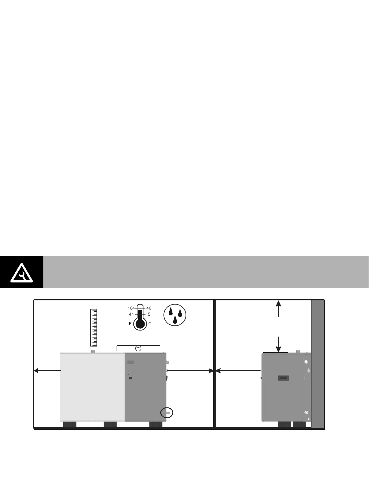
Location
The SE series humidifiers are designed to be either floor mounted or stand mounted (stand
optional). SE 50 models can also be ceiling mounted with the optional ceiling installation kit,
part number 2520345.
Install only in areas with ambient temperature 41-104 °F (5 – 40 °C) relative humidity 5 -
95% (non condensing).
Ensure mounting surface is strong enough to support the full weight of the humidifier and
accessories (see Table 3: SETC/P Specifications).
Install in location where electrical power, boiler steam, and drain can be connected to the
humidifier.
When possible install below the steam distributor. If mounted above the steam distributor
take care to provide proper steam line routing and proper condensate traps.
DO NOT locate the humidifier any further then absolutely necessary from the steam
distributor location as net output will be reduced as a result of heat loss through the steam
line.
Condensate drain is located close to the bottom of the humidifier. Locate the unit so that
condensate line slopes down to boiler or use pump (by others) to lift to boiler. Use stand if
necessary.
Avoid mounting humidifier on combustible surfaces including (but not limited to) carpet, tile,
or certain insulating materials.
Clearance dimensions shown are for reference only and are the minimum required for
maintenance of the humidifier. Consult local and national codes before final location and
installation. Nortec does not accept responsibility for installation code violations.
Figure 6: Installation Location / Clearance
11 | Installation
Page 15
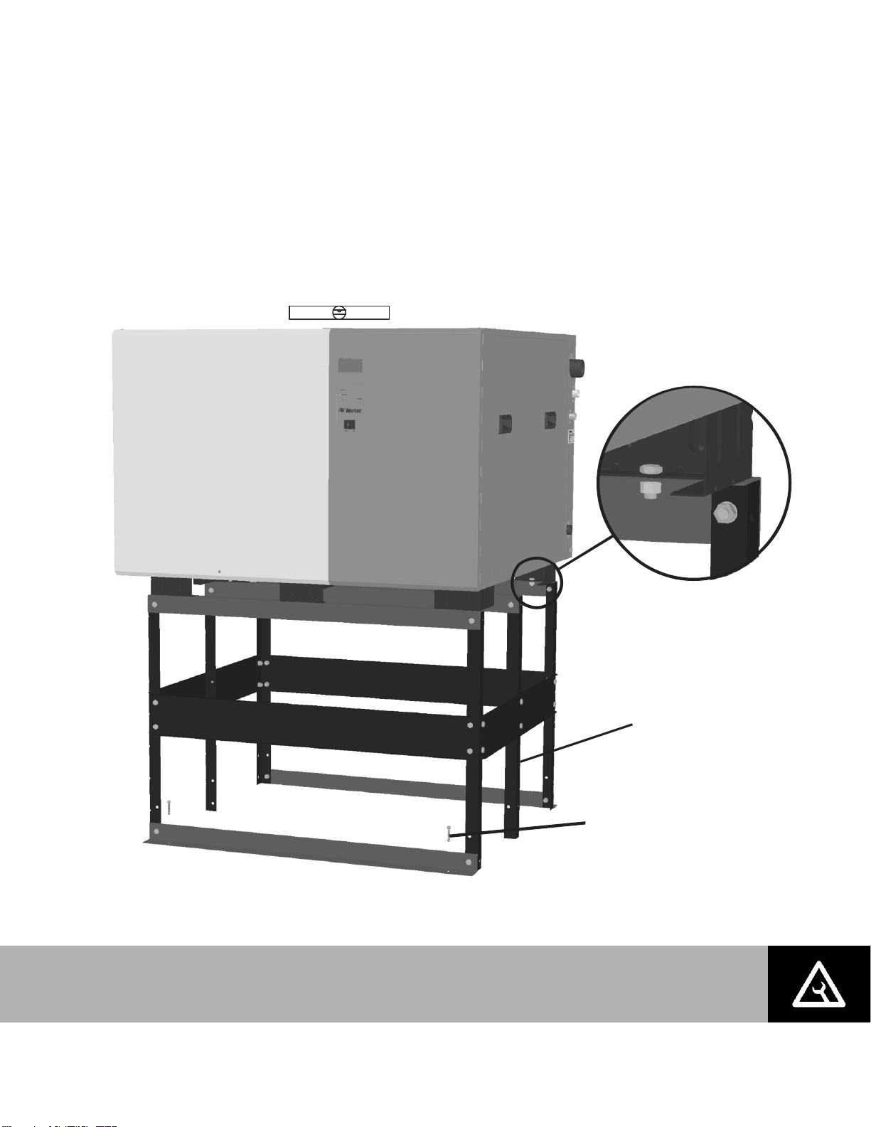
Note: The humidifier must be secured to the stand (hardware provided) and the stand
must be secured to the floor (hardware by others).
Center support only
present on SE 525
and larger.
Fasten SE humidifier
to stand with bolts,
lock washers, and nuts
provided. Tighten
to 200 in-lb (22.6 Nm).
Mount stand on level surface
Ensure humidifier is Level
Secure stand to floor
four places.
(hardware by others)
Note:
Mounting on Optional Stand
The optional SE floor stand positions the SE humidifier at a convenient working height and
provides additional clearances for sloping drains. The stand must be assembled at site.
Assemble the stand according to the instructions that are provided with it.
Ensure the stand and humidifier are installed on a level surface
Permanently secure the stand to the floor via the holes in the leg support plates following
any local codes or regulations.
Figure 7: Mounting on Optional Stand
Installation | 12
Page 16
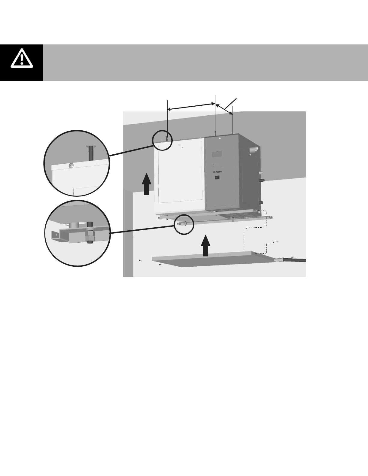
Note:. The SE50 requires regular maintenance including removal of scale from the
heat exchanger and tank. Make sure it is installed in a location where the
maintenance can be performed.
1
4
.
5
i
n
.
(
3
6
.
8
c
m
)
12.8 in.
(32.6 cm)
Anchor 3/8 in (M10)
support rods to ceiling
(by others)
Support rods and hardware
(by others) must not extend
below support bracket flange.
Sloped drain
1/2 in. pipe
(by others)
Ceiling Mounting (SE50 Only)
Nortec offers an optional ceiling mounting kit (part number 2520345) which allows the SE50 to
be ceiling mounted with zero clearance to the ceiling. Follow the following guidelines for
Figure 8: Ceiling Mounting the SE50
installation.
Follow the instructions provided with the ceiling mounting kit.
Install in a location where regular maintenance can be performed. Provide clearance as
shown in Figure 6: Installation Location / Clearance.
The SE50 weighs 180 lb (82 kg) when filled with water and without any accessories or
piping. It is the installer’s responsibility to calculate the total weight which must be
supported, to ensure the ceiling structure is adequate, and to install support rods and to
connect drain pan per local codes and regulations.
The humidifier cannot be used as a structural member. All piping connected to the unit
must be supported independently.
A drain line emptying into an open drain must be connected to the ceiling kit drain pan.
Nortec recommends a 1/2 in. pipe with sufficient slope to ensure any water collected in the
pan will drain from it.
13 | Installation
Page 17
Note:
Drain Water is very hot, do not use plastic pipe for drain or condensate lines, do not
drain to public sink. Route to floor drain or equivalent.
Supply cold potable water, deionized water or reverse osmosis water at 30 - 80 PSIG.
Hardness 5-7 grain or 90 – 120 mg/l (as Ca+2 as CaCO3)
Total Dissolved Solvents (TDS) 0.5-3 mg/l or Conductivity 1 to 70 mho/cm
Chlorides 0-25 ppm PH 7.2-8.5 Alkalinity 30-130 mg/l (as CaCO3)
Min. 1 1/4 in. OD drain line.
Slope down. Increase size
if combining multiple drains.
0.75 in. (19 mm). OD
un-threaded drain outlet
Connect with hose cuff
and hose clamps.
Air gap required.
2 1/2 in. to 1 1/4 in. copper
reducer is ideal.
Hose/line must not touch
the bottom of the funnel.
Always install a water
shut-off valve.
1/2 in. NPT
Use union to connect
supply pipe to unit.
*Pipe, unions, and water shut-off valve not supplied by NORTEC.
Axillary drain, 1/2 in. female NPT
For draining tank without pump. Leave
valve closed except if freeze protection is installed.
Plumbing
All water supply and drain line connections must be installed in accordance with local
See Table 3 and Table 4 on page 7 for supply water flow requirements.
Install water shut off valve and union before humidifier to facilitate servicing.
Insure drain line is adequately sized to provide free and easy draining and that an air gap is
Auxiliary drain connection with manual shut off valve is recommended for all units. Valve to
High hardness or silica content supply water may require increased maintenance.
Unit damage caused by water quality outside of the specified ranges is not covered under
Figure 9: Water Supply and Drain Connection
plumbing codes.
installed as shown. See Table 3 and Table 4 on page 7 for flow requirements.
be left closed on units without freeze protection option installed. Valve to be left open on
units with freeze protection option installed except during servicing.
warranty.
Installation | 14
Page 18
Note:.
Pressurized steam line installation to be performed by a qualified installer.
Damage to SE heat exchanger will occur if it is exposed to pressure above 20 psi..
A safety relief valve must be installed to prevent the SE from being exposed to
pressure in excess of 15 psi when the SE is connected to a medium or high
pressure boiler via a pressure reducing valve.
The steam supply line must be designed to provide design pressure at the CV valve
when there is 100 % demand (CV valve completely open). Pressure losses in the
steam supply line will reduce SE output.
Condensate must be drained to a non-pressurized boiler condensate return line.
Pressurized condensate
header
Not pressurized
condensate header
(slope down)
F&T Trap
Pressure
gauge (optional)
Isolation Valve
Wye Strainer
CV Valve
(see table 3)
Condensate Drain
Port (see table 3)
Boiler steam
inlet port
(see table 3)
Boiler steam supply
line. Max 15 psi, Min 5 psi
measured at CV Valve
6 in.
(15 cm)
Max
Actuator
Condensate drain line.
Gravity feed to boiler.
Use pump if condensate
must be lifted.
Note: Nortec supplies CV valve, actuator
and wye strainer. All other
components and fittings by others.
Boiler steam
inlet port location
on SE 1050
S
l
o
p
e
d
o
w
n
o
n
l
y
Boiler Steam and Boiler Condensate Return
15 | Installation
Figure 10: SE Boiler Steam and Condensate Connection
Page 19
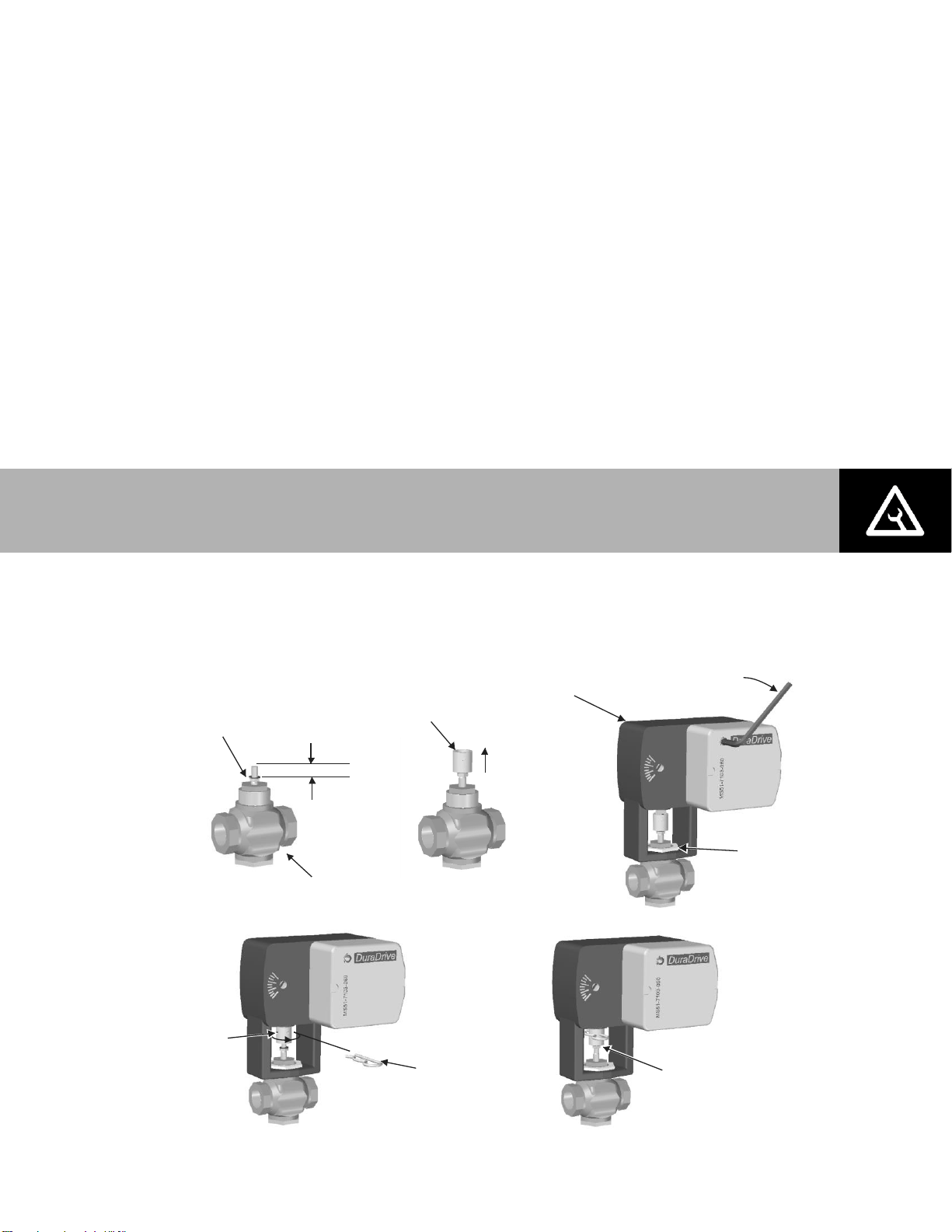
Caution: Condensate leaves the steam traps inside the SE under slight pressure. Steam
flash could occur in the condensate drain line.
1/2 in. (1.2 cm)
min.
Install jam nut
and lock washer
Install stem
extension
Install and
tighten
mounting nut
2 turns then
push in and
1/8 turn to lock
Actuator
CV Valve
Raise valve
stem to full up
Insert
connecting
pin
Turn stem
extension
until holes
line up
Tighten jam nut
against stem extension
Nortec supplies a CV valve, actuator and wye strainer with each SE humidifier. The port sizes of
the CV valve, boiler steam inlet port, and condensate drain port are given in Table 3: SETC/P
Specifications on page 7. Follow the following guidelines for installation.
All steam line connections must be installed in accordance with local codes.
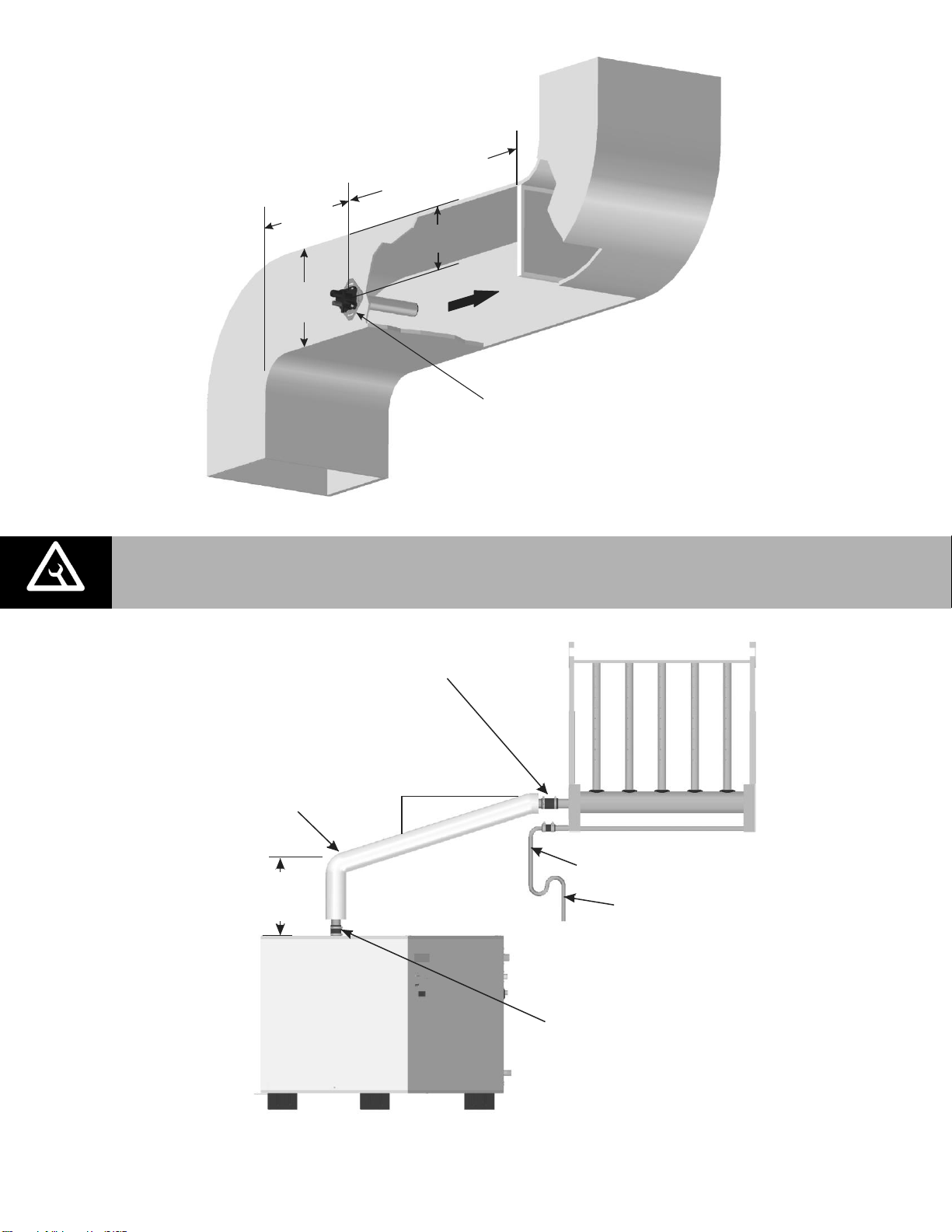
Install the CV valve actuator following the procedure in Figure 11: CV Valve Actuator
Installation after the CV valve is installed on the steam line. Wire the actuator as described
in CV Valve Actuator Wiring on page 29.
Boiler steam supply line design is the responsibility of the installer. The boiler steam supply
line must be designed so that that design pressure is present at the CV valve when the CV
valve is completely open (100% demand). The diameter of the supply line up to the wye
strainer may have to be oversized to insure proper steam pressure.
The SE will operate on supply steam pressures between 5 and 15 psi measured at the CV
valve. Lower steam supply pressures will result in lower output. See Table 4: SETC/P
Capacities and Water Consumption on page 7 for capacities at different supply pressures.
If condensate cannot be gravity fed to the boiler then a pump must be used to lift the
condensate. See Spirax Sarco (www.spiraxsarco.com) and others for pumps and additional
information on condensate mananagement.
The boiler steam and condensate connections are independent. Boiler steam condensate
should be returned to the boiler and should not be mixed with water from the tank drain.
The steam supply pressure can be entered into the SETC control software to provide display
of unit output. See Pressure Based on page 56.
Figure 11: CV Valve Actuator Installation
Installation | 16
Page 20
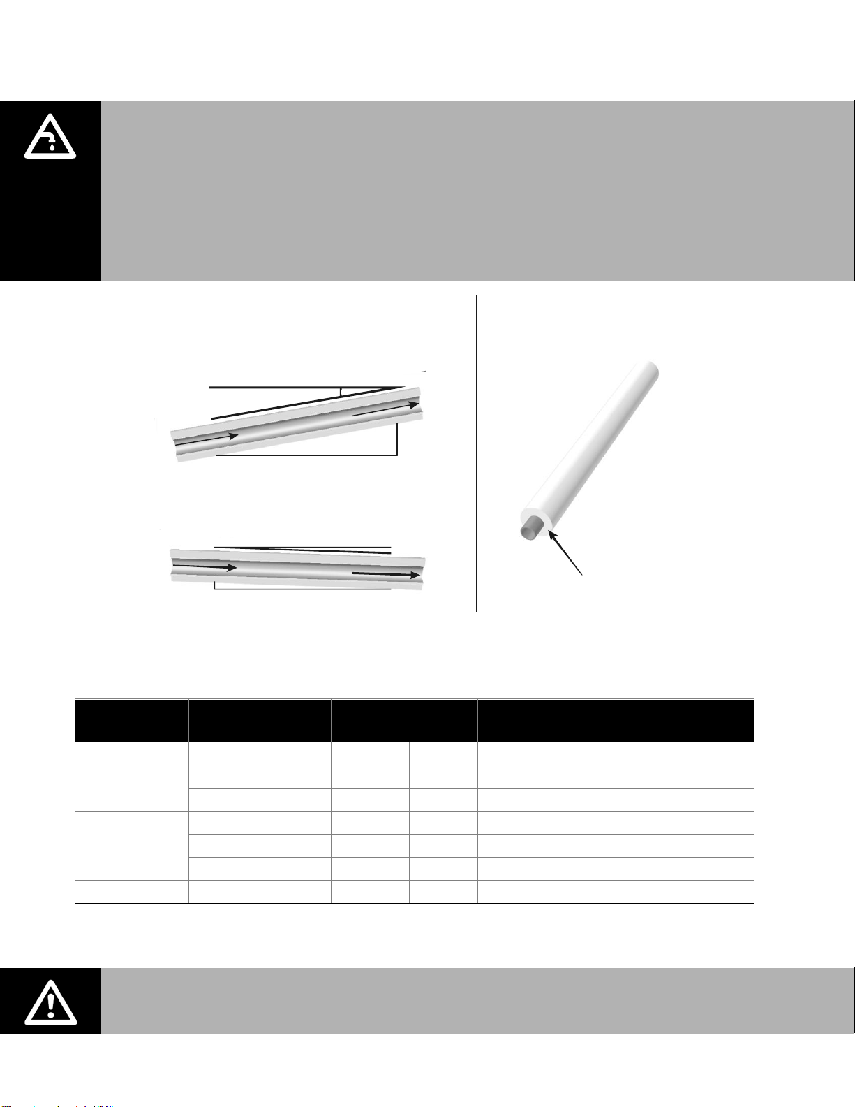
Steam Line
Material
Lb/hr (kg/hr)
Steam Line Length
ft m
Steam Line Description
Copper Tube
0-100 (0-45)
0-90
0-27
1 1/2 in. MED-L Tubing (1.625 in. OD)
101-250 (46-113)
0-180
0-54
3 in. MED-L Tubing (3.125 in. OD)
251-650 (114-295)
0-260
0-79
**4 in. MED-L Tubing (4.125 in. OD)
*Stainless Steel
Tube
0-100 (0-45)
0-90
0-27
1.75 inch Tube x 0.065 inch thick wall
101-250 (46-113)
0-180
0-54
3 inch Tube x 0.065 inch thick wall
251-650 (114-295)
0-260
0-79
**4 inch Tube x 0.065 inch thick wall
Nortec Hose
31-100 (14-45)**
<15
<4.5
***Part Number 1328820 (1 3/4”)
S
t
eam
Dire
ction
Ste
am
D
ire
c
tio
n
S
t
e
a
m
D
i
r
e
c
t
i
o
n
2 in.
(5 cm)
1 ft (30 cm)
1ft (30 cm)
0.5 in.
(12 mm)
10 Degrees
2 Degrees
Use Appropriate Slope Insulate Pipe
1 in. (2.5 cm) pipe
insulation
MAIN RULES FOR ATMOSPHERIC STEAM LINES
Slope the steam lines.
Trap condensate (Use full size ‘T’ for Traps).
Steam lines must not have any restrictions which could cause back pressure.
Insulate with 1.0 in. (2.5 cm) pipe insulation.
Follow recommended materials, size and length see tables.
Steam Hose Odour: Nortec hose may generate a slight odour during initial use. This
odour is temporary and will disappear after a short period of time.
Steam Lines and Condensate Returns
Figure 12: Main Steam Line Requirements
Table 5: Recommended Steam Line Material
Note: * Use only stainless steel tube for reverse osmosis and deionized water applications.
** Use 2 x 4 in. steam lines for steam capacities higher than 750 lb/hr (307 kg/hr)
*** Use one steam hose per 100 lb/hr (45 kg/hr) of output.
17 | Installation
Page 21
Unit
Size
Steam Output
.
lb/hr (kg/hr)
Steam Outlet and
Line Size .
Copper (SST)
Maximum
Length .
ft (m)
Possible Loss
.
lb/hr/ft (kg/hr/m)
Possible Loss at
Max. length
lb/hr (kg/hr)
50
50
(23)
1 1/2
(1 3/4)
37
(11)
0.11
(0.16)
4
(2)
100
100
(45)
1 1/2
(1 3/4)
90
(27)
0.11
(0.16)
10
(4.5)
175
175
(80) 3 (3)
90
(27)
0.16
(0.24)
14
(6.5)
250
250
(114) 3 (3)
180
(55)
0.16
(0.24)
28
(13)
375
375
(170) 4 (4)
180
(55)
0.22
(0.33)
39
(18)
525
525
(239) 4 (4)
220
(67)
0.22
(0.33)
48
(22)
750
750
(341)
2X 4
(4)
260
(79)
0.44
(0.66)
114
(52)
1050
1050
(477)
2X 4
(4)
260
(79)
0.44
0.66)
114
(52)
Tube
Diameter in.
90 Degree
Elbow ft (m)
45 Degree
Elbow ft (m)
Side Outlet Tee
ft (m)
Gate Valve
ft (m)
Globe Valve
ft (m)
1 1/2 or 1 3/4
3.5
(1)
1.75
(0.5)
7
(2.1)
0.8
(2.4)
34
(10) 3 5
(1.5)
2.5
(0.75)
11
(3.3)
1.1
(3.1)
54
(16) 4 8
(2.4)
4
(1.2)
15
(4.5)
1.6
(0.5)
80
(24)
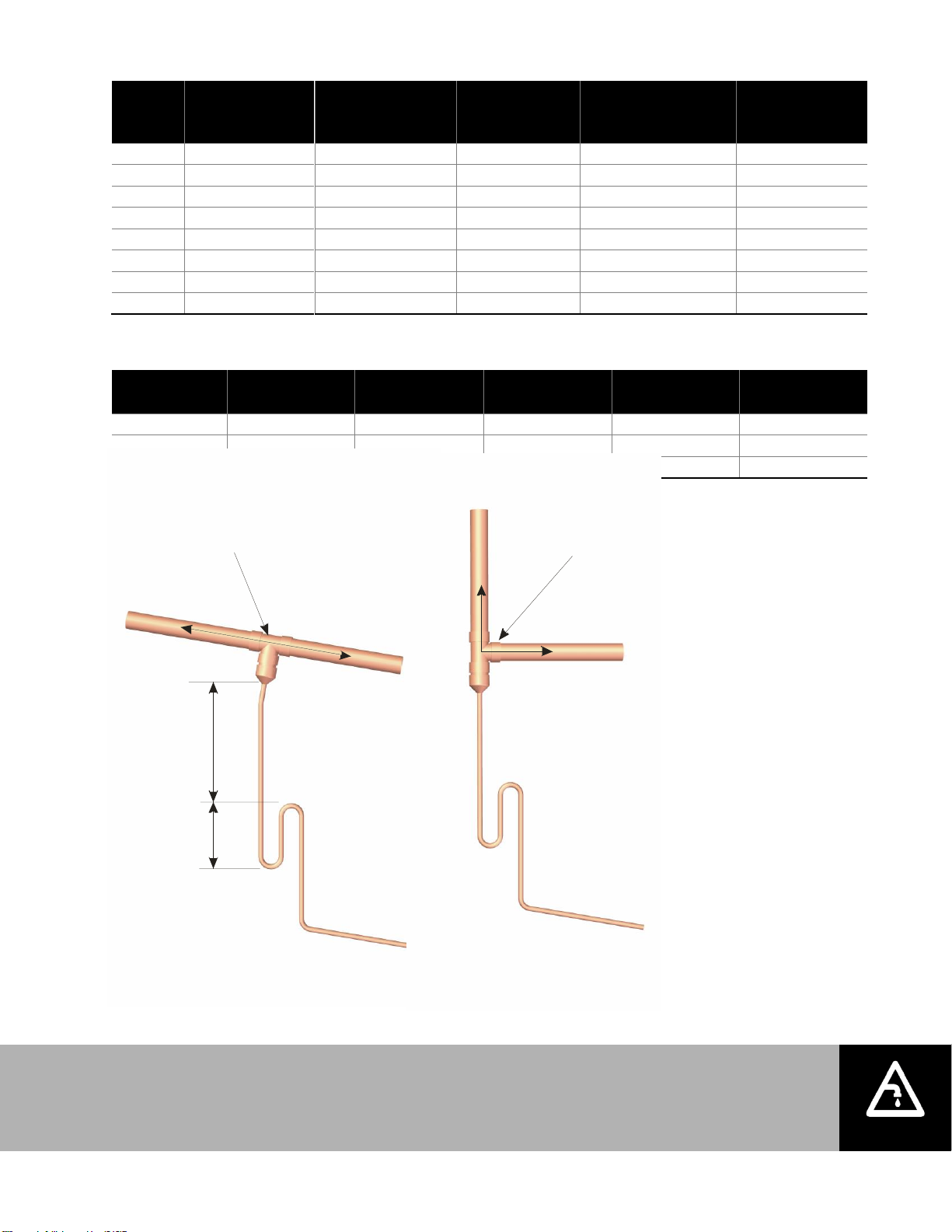
Note: Condensate should not be routed to a sink used frequently by personnel. Route to
a floor drain or equivalent. Condensate normally cools in traps but is still hot. A SAM-e or
larger steam line generates more condensate and water may not cool in the trap. A drain
water cooler option may be installed if required by code.
12 in. (30 cm)
min drop to
top of ‘P’ Trap
P Trap
min 8 in.
(20 cm)
plus duct
static pressure
Tee is same size
as steam line
Use a full size tee, not a 90
degree elbow for vertical
to horizontal transitions.
‘P’ Traps Use:
- NORTEC 0.375 in condensate hose .
- 1/4 in Med-L copper tubing, or
- 0.375 in stainless steel tubing
Condensate drains must be sloped down.
Route to humidifier fill cup if possible.
Table 6: Maximum Recommended Length of Steam Line
NOTE: See Table 7 for equivalent length of common fittings.
Table 7: Equivalent Length of Some Common Fittings
Figure 13: Condensate Traps
Installation | 18
Page 22
12 in.
(30 cm)
min.
Calculated absorption
distance to any obstruction
or 8-10 ft (2.4 - 3 m)
if unknown
Mount distributor
to side of duct
2 x duct
height min.
2/3 Duct
height
Note:
Refer to distributor or SAM-e installation manuals for detailed installation instructions.
Hose cuff
with clamps
2 in. (5 cm)
min.
1 ft (30 cm)
‘P’ Trap
1 ft (30 cm)
min. before
anybend
Condensate line
Use steam hose between
steam outlet and steam line.
Insulated copper
steam line. Support
so weight is not on
steam outlet.
To drain
Figure 14: Distributor Location in Duct
Figure 15: SAM-e/Steam Distributor Above Humidifier (Copper Steam Line Shown)
19 | Installation
Page 23
‘P’ Trap
Install Condensate Tee
Before Distributor
1 ft (30 cm)
min. Before
any bend
Min 12 in.
(30 cm)
radius
Hose will soften
over time
proper support
Is necessary
Support Brackets
1 ft (30 cm)
min.‘P’ Trap
To drain
To drain
1ft (30 cm)
min. before
any bend
Obstruction
Use full size condensate tee
at low point. Slope lines up
to “T” and immediately after it.
1 ft (30 cm)
min.
1 ft (30 cm)
0.5 in. (1.2 cm) min.
To drain
To drain
‘P’ Trap
‘P’ Trap
Figure 16: Steam Distributor/SAM-e Below Humidifier (Hose Shown)
Figure 17: Steam Under Obstruction (Copper Steam Line Shown)
Installation | 20
Page 24
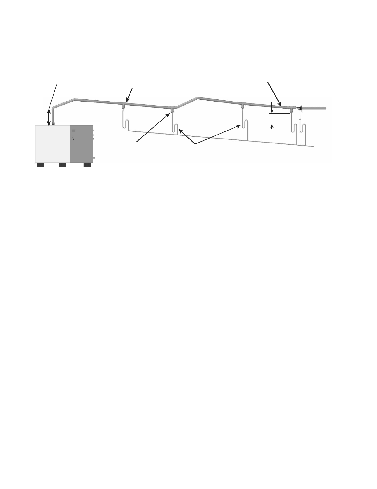
1 ft (30 cm)
min before turn
Condensate
tee every
15-20 ft
(4.5 - 6 m)
Condensate
tee at low
points
Individually trap multiple condensate
returns before joining on common line.
To Drain
Install condensate tee
before distributor
Method for Longer Runs With Limited Vertical Space
1 ft (30 cm)
min.
Figure 18: Long Steam Run
21 | Installation
Page 25
Caution:
Wiring to be performed by a licensed Electrician.
All SE humidifiers operate on 120 VAC, single phase, 60 HZ power. Refer to
specification label for power requirements.
L1
Neutral
Ground
L1
Neutral
Ground
SETC / P Primary Power
Single Phase Supply
Note:
1
2
3
Dedicated external fused
disconnect must be installed.
Fusing must not exceed max
circuit protection as indicated
on the specification label.
Ensure that adequate power is
available to carry full humidifier
amp draw as indicated on the
specification label.
All wiring to be in accordance
with national and local electrical
codes.
E
X
T
I
N
T
High voltage
terminal block
Knockouts provided
in top and bottom panels.
Install strain relief (by others)
Dedicated circuit
breaker or fused
disconect.
Electrical
Figure 19: Primary Power Connection
Installation | 22
Page 26
Note: Regardless of selecting on/off or modulating control method, Nortec humidifiers
must have a closed circuit across their on/off security loop control terminal to
operate. Nortec highly recommends the use of a high limit humidistat and an air
proving switch in series for this function.
Caution: Failure to wire the humidifier in accordance with the wiring instructions could
cause permanent damage. Such errors will void the warranty.
1
2 3
10 ft min.
Humidity
Control
(return air
duct or
in room)
Duct High
Limit
Air
Proving
Switch
External Controls
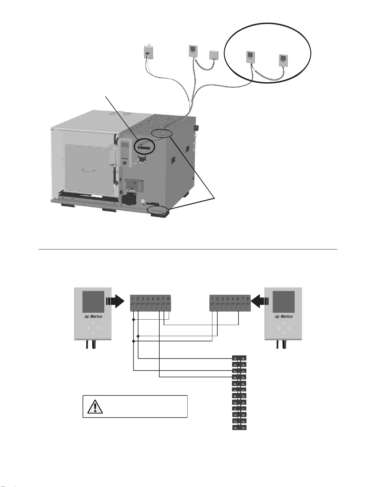
Control Wiring
Controls are available from Nortec as accessories. If controls were not ordered with humidifier
they must be supplied by others. The following information is relevant to all controls, factory
supplied or otherwise. For wiring use minimum of 18 AWG and keep as short as possible.
The SETC humidifier can be operated with two modulating inputs. The SEP has one modulating
input which can be used for a duct high limit or humidity control. Both the SETC and SEP can be
operated as On/Off. See Control Setting on page 53 for SETC configuration and On/Off or
Modulating Control (J10) on page 61 for SEP configuration.
Control Location
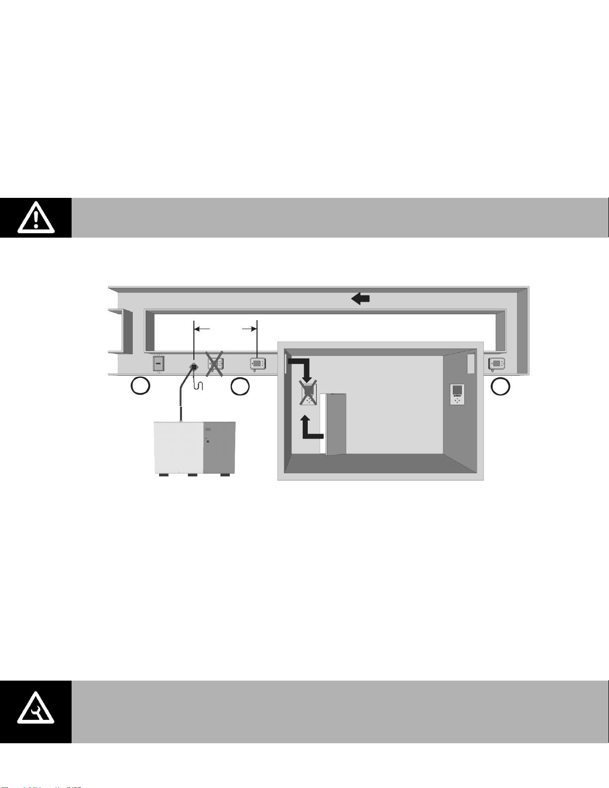
Figure 20: Control Location
1 Air Proving Switch
Locate so that it can sense air flow or lack of it.
2 Duct High Limit
SETC can be modulating, On/Off, or a humidity sensor. SEP can be modulating or On/Off.
Locate at least 10 feet from steam distributor or far enough that under normal conditions
steam is fully absorbed.
3 Humidity Control
SETC can be Modulating, On/Off, or a Humidity Sensor. SEP can be modulating or On/Off.
Can be located either in return air duct (preferred) or in room being humidified.
Mount in area representative of room humidity (draft, doorways, sunlight, or overhang such
as a shelf can affect reading). Avoid placing near discharge diffuser of humidified air.
23 | Installation
Page 27
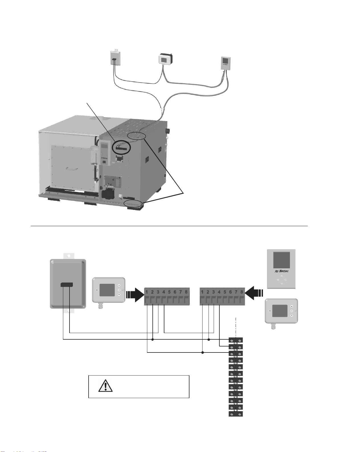
Figure 22: Digital On/Off
Note: 1
2
3
4
Air Proving
Switch
Humidity Control
2548731 - On/Off
Wall Humidistat
Duct High Limit
2548732 - On/Off
Duct Humidistat
Humidifier Terminal Strip
Knockouts provided
in top and bottom panels.
Install strain relief (by others)
Humidifier will run when circuit between
terminal 1 and 2 on humidifier is closed.
Terminal 1 is 24VAC Hot, turn unit off to
avoid shorting while wiring.
Digital Humidistats require 24 VAC power
from terminals 1 and 3 of humidifier.
Humidity Control can be wall mounted
as shown or return air duct mounted.
1- 24 VAC
2 - On/Off Loop
3 - Ground
4 - Control Signal
5 - Limit Signal (SETC only)
6 - 5 VDC
7 - Ground
8 - Full Tank Blow Down
9 - Ground
10 11 - Actuator power
12 -
Actuator power
0-10 VDC Out
1 - Ground
2 - 24 VAC
3 - Common
4 - Digital Out
5 - Fan Relay
6 - Fan Relay
7 - NTC Sensor
8 - NTC Sensor
Air Proving Switch
Wire to make when
sensing air flow
Duct High Limit
2548732 - On/Off Duct Humidistat
Wire to make on drop in humidity
Humidity Control
2548731 - On/Off Wall Humidistat or,
2548732 - On/Off Duct Humidistat
S
E
E
X
T
Connect 24 VAC,
term inal 1 of humidifier to
term inal 2 of controllers.
Com
N/O
1 - Ground
2 - 24 VAC
3 - Common
4 - Digital Out
5 - Fan Relay
6 - Fan Relay
7 - NTC Sensor
8 - NTC Sensor
OR
On/Off Control Wiring
Figure 21: On/Off Controls
Installation | 24
Page 28
1 - Ground
2 - 24 VAC
6 - Analog Out
8 - Temperature
Insert On/Off
controls or jumper
between 1 and 2
1510142 - Digital Wall Humidistat
1 - Ground
2 - 24 VAC
6 - Analog Out
7 - Analog In
8 - Temperature
2520266 - Digital Duct Humidistat
Package
S
E
Analog Out - 3
24 VAC - 2
Ground - 1
Connect 24 VAC, terminal
1 of SETC/P to terminal
2 of controllers.
1- 24 VAC
2 - On/Off Loop
3 - Ground
4 - Control Signal
5 - Limit Signal (SETC only)
6 - 5 VDC
7 - Ground
8 - Full Tank Blow Down
9 - Ground
10 11 - Actuator power
12 -
Actuator power
0-10 VDC Out
E
X
T
Figure 24: Digital Modulating Humidistats
Install On/Off controls or jumper between
terminal 1 and 2 of humidifier in order to run.
Terminal 1 is 24 VAC Hot, turn unit off to
avoid shorting while wiring.
High Limit Humidistat must be duct mounted.
It can be On/Off or modulating.
Control Humidistat can be mounted in space
or in return air duct and can be On/Off or
modulating.
The SEP can only accept one modulating
signal.
Air Proving
Switch
High Limit Humidistat
Control Humidistat
Humidifier Terminal Strip
Knockouts provided
in top and bottom panels.
Install strain relief (by others)
Note: 1
2
3
4
5
Modulating Control Wiring
25 | Installation
Figure 23: Modulating Controls
Page 29
Air Proving
Switch
Duct High
Limit
2520261 - Digital
Wall W/O Sensor
1509858 - Wall
Sensor
Wire wall sensor to digital display as shown
below, wire digital display to humidifier as shown
for 1510142 - Digital Wall Humidistat.
+
1509858 - Wall Sensor
2520261 - Digital Wall W/O Sensor
Humidifier Terminal Strip
Knockouts provided
in top and bottom panels.
Install strain relief (by others)
1 - Ground
2 - 24 VAC
6 - Analog Out
7 - Analog In
8 - Temperature
1 - Ground
2 - 24 VAC
6 - Analog Out
1509858 - Wall
Sensor
2520261 - Digital
Wall W/O Sensor
1- 24 VAC
2 - On/Off Loop
3 - Ground
4 - Control Signal
5 - Limit Signal (SETC only)
6 - 5 VDC
7 - Ground
8 - Full Tank Blow Down
9 - Ground
10 11 - Actuator power
12 -
Actuator power
0-10 VDC Out
Connect 24 VAC, terminal
1 of SETC/P to terminal
2 of controllers.
Figure 25: Digital Wall Humidistant – Remote Wall Sensor
Figure 26: Remote Wall Sensor Wiring
Installation | 26
Page 30
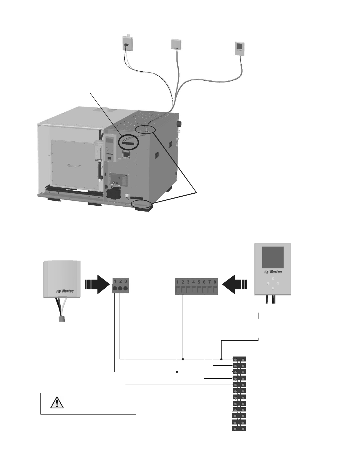
Figure 28: Digital
Air Proving
Switch
Duct High Limit
1509857 - 2-10V
Duct Humidity
Transducer
Humidity Control
1509858 - 2-10V Wall
Humidity Transducer
Install On/Off controls or jumper between
terminal 1 and 2 of humidifier
Terminal 1 is 24 VAC Hot, turn unit off to
avoid shorting while wiring.
Duct High limit can be duct humidity
transducer as shown or duct On/Off
humidistat.
Humidity Control can be wall humidity
transducer as shown, duct humidity
transducer, or On/Off humidistat.
.
Humidifier Terminal Strip
Knockouts provided
in top and bottom panels.
Install strain relief (by others)
Note: 1
2
3
4
1 - Ground
2 - 24 VAC
6 - Analog Out
1509858 - 2-10V Wall Humidity
T ransduc e r
1 - Ground
2 - 24 VAC
3 - Analog Out
Insert On/Off
controls or jumper
between 1 and 2
1509857 - 2-10V Duct Humidity
T ransduc e r
Connect 24 VAC,
term inal 1 of SETC to
term inal 2 of controllers
1- 24 VAC
2 - On/Off Loop
3 - Ground
4 - Control Signal
5 - Limit Signal (SETC only)
6 - 5 VDC
7 - Ground
8 - Full Tank Blow Down
9 - Ground
10 11 - Actuator power
12 -
Actuator power
0-10 VDC Out
E
X
T
S
E
Transducer Control Wiring (SETC Only)
27 | Installation
Figure 27: Transducers
Page 31

Figure 30: Outdoor Temperature Sensor (Modulating Control)
1 - 24 VAC
2 - Temperature
2520263 - Outdoor Temperature
Sensor
Connect 24 VAC, terminal
1 of humidifier to terminal
2 of controllers.
Note:
1 2 The Temperature sensor is
intended for duct mounting.
Locate the temperature sensor
near the fresh air intake. This
will ensure accurate representation
of the outdoor air temperature.
2548731 - On/Off Wall Humidistat or,
2548732 - On/Off Duct Humidistat
1 - Ground
2 - 24 VAC
3 - Common
4 - Digital Out
5 - Fan Relay
6 - Fan Relay
7 - NTC Sensor
8 - NTC Sensor
OR
Insert Other
On/Off
controls
in series
1- 24 VAC
2 - On/Off Loop
3 - Ground
4 - Control Signal
5 - Limit Signal (SETC only)
6 - 5 VDC
7 - Ground
8 - Full Tank Blow Down
9 - Ground
10 11 - Actuator power
12 -
Actuator power
0-10 VDC Out
E
X
T
S
E
Optional Outdoor Temperature Reset
Figure 29: Outdoor Temperature Reset
Each digital controller is equipped with an integrated reset function that can reduce the
setpoint during cold weather operation. This will prevent condensation on windows and
building structures. The above graph illustrates how the setpoint reset feature operates.
On modulating humidistats this feature is enabled by removing the jumper from terminals 8
and 1 on the humidistat and wiring the outdoor temperature sensor to these terminals. On
On/Off humidistats this feature must be activated with the humidistat’s keypad.
When the outdoor temperature setback feature is in effect, the humidistat will normally
display the calculated setpoint limit based on the outdoor air temperature. A snowflake will
also be displayed to indicate cold weather operation. When any key on the controller is
pressed, the LCD screen will display the customer specified setpoint for a short duration.
Installation | 28
Page 32

9 - Ground
10 - Actuator 24 VAC
11 - Actuator Ground
12 - 0-10 VDC Out
Y/Bk
Gr
Note: 1 Wire the CV valve actuator
to the humidifier’s low voltage
termina l strip.
2 Use minimum of 1 8 AWG wire
and ke ep a s s h o r t a s p o ss ible.
3 After installation a n d p o we r in g
humidifier verify that tra ve l o f
actua to r a t fu ll de man d is to th e
fully ope n p o sition .
SE 1050 low
voltage terminal strip
Bk
R
9 - Ground
10 - Actuator 24 VAC
11 - Actuator Ground
12 - 0-10 VDC Out
Y/Bk
Bk
R
SE 50 - 750
Actuator
SE 1050
Actuator
SE 50 - 750 Terminal Strip
1 - Ground
2 - 24 VAC
6 - Analog Out
8 - Temperature
1510142 - Digital Wall Humidistat or,
2520266 - Digital Duct Humidistat Package
1 - 24 VAC
2 - Temperature
Insert On/Off
controls or jumper
between 1 and 2
2520263 - Outdoor Temperature
Sensor
Connect 24 VAC, terminal
1 of SE to terminal
2 of controllers.
Note:
1 2 The Temperature sensor is
intended for duct mounting.
Locate the temperature sensor
near the fresh air intake. This
will ensure accurate representation
of the outdoor air temperature.
E
X
T
S
E
1- 24 VAC
2 - On/Off Loop
3 - Ground
4 - Control Signal
5 - Limit Signal (SETC only)
6 - 5 VDC
7 - Ground
8 - Full Tank Blow Down
9 - Ground
10 11 - Actuator power
12 -
Actuator power
0-10 VDC Out
Figure 31: Outdoor Temperature Setback (On/Off Control)
CV Valve Actuator Wiring
29 | Installation
Figure 32: CV Valve Actuator Wiring
Page 33

Steam
Unit ON
Error
Service
NO
COMNOCOMNOCOM
NC
NO
COM
NC
Remote Relay Board Wiring
The SETC (not SEP) remote relay board provides the output signal for the CV Valve Actuator and
includes 4 relays that can provide remote status indication. The remote relay board is located
as shown in Figure 33: Remote Relay Board Wiring. The PCB with the relays includes markings
which indicate the function of each terminal on the board. The relays indicate the following
status;
1 Unit On – The normally open relay is closed when the humidifier has power and the On/Off
switch is set to on.
2 Steam – The normally open relay is closed when the control board sends a signal to the CV
valve actuator to open the CV valve and steam is being produced.
3 Service – The relay can be wired to open (NC) or close (NO) when a warning is displayed on
the humidifier display and the yellow service LED is illuminated.
4 Error – The relay can be wired to open (NC) or close (NO) when a fault is detected by the
humidifier controls.
Figure 33: Remote Relay Board Wiring
Installation | 30
Page 34

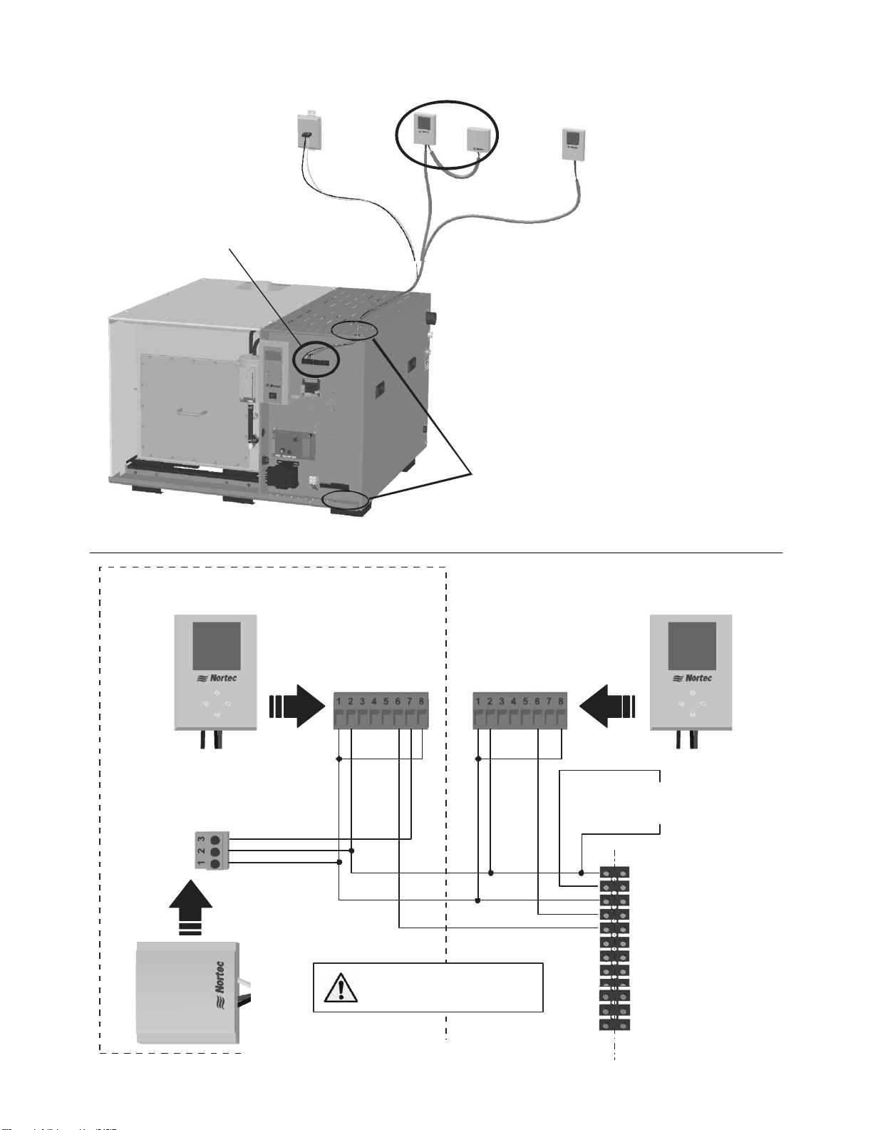
Daisy chain pole 2 and 3
of terminal of the
driver board.
Do not reverse polarity.
Do not connect to pole 1 or 4.
Note:
J2a-RS485
Master
Slave 1 Slave X
Daisy Chain
up to 16
Humidifiers
Staged Modulation Wiring (SETC Only)
Connect up to 10 units (equivalent of 10,500 lb/hr (4,770 kg/hr)) using 18-24 AWG multi-
strand, twisted pair, shielded cable.
Connect humidistats/transducers and On/Off safety loop to master unit only.
See Multi Mode on page 54 and Multi Unit Op. Range on page 56 for software configuration.
31 | Installation
Figure 34: Staged Modulation Wiring
Page 35

Note:
For installation of options and accessories follow the instructions that are provided with
them.
Options and Accessories
Remote Blower Pack
Remote blower packs are available for the SETC/P for applications where steam for
humidification must be introduced directly into the space being humidified. For instructions on
installing the remote blower pack refer to the installation instructions supplied with it. The
steam line and condensate return instructions provided in this manual are also applicable to
remote mounted blower packs.
The blower packs include a safety relay which should be used to prevent the humidifier from
operating if the blower packs do not have power. Wire humidifier security loop in series through
all blower packs and other On/Off controls.
Drain Water Cooling (External)
Pneumatic and electric drain water coolers are available from Nortec for installation outside the
humidifier or on condensate drains from steam traps, distributors, and SAM-e headers. If
condensate cannot be routed back to the humidifier tank via the humidifier’s fill cup then an
external drain water cooler may be required to meet regulations restricting the temperature of
hot water that can be fed to drain. The external drain water cooler is only available for field
installation.
Installation | 32
Page 36

Start Up
34 Installation Check
35 SETC User Interface
35 Manual Drain Switch
36 Start Up Procedure
37 Status Screens
39 Nortec Digital Controls
40 Staged Modulation (SETC Only)
40 Nortec LINKS 2
40 Nortec ONLINE
41 SETC/P Pre-Start Up Checklist
42 SETC/P Start Up Checklist
33 | Start Up
Page 37

Steam Line
- Adequate slope
- No restrictions
- No kinks (hose)
- Condensate traps
on long runs
P Trap(s) .
.
with 12 in
(30 cm) min drop(s)
.
Disconnect
,
,
Correct voltage
amps phase
On/Off Controls
(Air Proving)
in series between
terminal 1 and 2
Min 10 ft (3 m)
Control
- Wired to terminal 4.
- On/Off in series
between terminal
1 and 2.
- In return duct or
location which
represents humidified
space (no drafts,
not by door, not
by diffuser).
1/2 in line min
30-80 PSI
Not plastic drain,
Not to sink.
High Limit
- Wired to terminal 5
- On/Off in series
between terminal
1 and 2
Mounting
- Unit level
- Service clearance
- Properly anchored
if on stand
Spec label
Calculated absorption distance
to any obstruction or 8 - 10 ft
(2.4 - 3 m) if unknown.
2 x duct height
from fan or
transition
Boiler Condensate
- Gravity fed to boiler
or lift pump
Air gap
Boiler Steam
- Max 15 psi
- Safety valve if from
med. or high press.
boiler.
- Design pressure
at 100% demand.
Actuator,
- Opens CV Valve
fully at 100%
demand
- Closes fully at 0%.
Installation Check
Before turning on power to the SE, inspect the installation to insure that it was carried out
correctly. Refer to Figure 35: Installation Check, to the SETC/P Pre-Start Up Checklist on page
41, and to the chapter on Installation that starts on page 9.
Figure 35: Installation Check
Start Up | 34
Page 38

Manual
drain
switch
Figure 37: Manual Drain Switch
LCD Display and
Input Buttons
.(Buttons used to navigate
status screens and
configure the humidifier,
correspond to icons on
the display)
Status LEDs
Software Drain Button
(Initiates a software
controlled drain)
On/Off Switch
(Turns humidifier On/Off)
SETC User Interface
Manual Drain Switch
Figure 36: SETC User Interface
The SETC/P has a manual drain switch that can drain the tank even if software is not
functioning. To drain the tank put the switch into the drain position. For normal operation the
switch should be in the off position.
35 | Start Up
Page 39

Warning: Damaged units or improperly installed units must not be operated. Damaged or
improperly installed units may present a danger to persons and property.
Request – xx%
Idle 0 lb/hr
04/30/09 14:25:22
Security loop: Closed
Menu
Note: on initial startup with cold water in the SE’s tank it may take 5 to 15 minutes
(depending on unit size) for the SE to reach a full boil and produce its rated steam.
Note:
Pressing the ESC key on the keypad will interrupt the float and drain test and the
humidifier will go straight to normal operating mode.
If an error is detected during the self-diagnostic sequence a Fault will be displayed.
See troubleshooting section for information on diagnosing and correcting faults.
SEP does not have an LCD display. The information on the SETC’s LCD depends on
the SETC’s configuration and actual operating conditions. It may vary from display
shown.
Start Up Procedure
1 Examine the humidifier and installation for damage and or improper installation.
2 Open the supply water shut off valve. If the auxiliary drain valve is installed ensure it is
closed.
3 Slowly open boiler steam isolation valve to allow boiler steam into the steam supply line up
to the CV valve.
4 Turn on the main power using the installed disconnect then turn the On/Off switch on the
front of the humidifier to On.
The LCD display will illuminate and the humidifier will perform
a self-diagnostic sequence during which the LED’s and
internal components will be momentarily activated. The SE
will then begin filling with water. The fill time is between 10
and 30 minutes depending on the size of the unit.
5 Once the water level is close to the top of the tank the LED
lights on the SE’s float chamber will light up and indicate the water level. On start up the SE
will perform a float and drain pump test by first filling until just the green LED is lit and then
draining until just the red LED is lit. After the float and drain test the humidifier is in normal
operation mode.
6 If On/Off or a control humidistats have been installed check and adjust the control setpoint
on the control and high limit humidistat (see Nortec Digital Controls on page 39). If
transducer controls have been installed then adjust the humidity setpoint using the keypad
and display (see Transducer Control on page 39)
7 When either the external humidistat or internal controller generate a demand for humidity
higher than 15%, the security loop is closed, and the float chamber indicates the tank is full
the SE will transmit a signal to the CV valve to open. Steam will flow into the SE’s heat
exchanger(s) and the SE will heat the water in its tank.
Start Up | 36
Page 40

Request – xx%
Idle 0 lb/hr
04/30/09 14:25:22
Security loop: Closed
Menu
CONTROL
Man Cap. : 100%
Demand : 55%
Limit : 80%
Output : 0 lb/hr
Menu
CONTROL
Man Cap. : 100%
RH CNT : 55%
CNT Set-Pt : 50%
RH Limit : 100%
LIM Set-Pt : 70%
Output : 0 lb/hr
Menu
HUMIDIFIER
Model : SETC 750
Capacity : 750 lb/hr
Multimode : StandAlone
REG Mode : Demand
Software : XVXX
Press. In : 15 psi
Menu
Caution:
Improper control configuration can result in over humidifying which can result in
damage to property.
See Advanced Control Configuration if the controls displayed in the control
information screen do not match those connected to the humidifier.
Request – 100%
Idle 750 lb/hr
04/30/09 14:25:22
Security loop: Closed
Menu
8 The green humidifying LED on the front of the humidifier will light up and the display will
indicated “Humidifying” and the amount of steam being produced (SETC only).
Status Screens
In addition to the main status screen the SETC includes several status screens which provide
additional information about the humidifier. The additional screens can be reached by pressing
the buttons corresponding to the left and right arrow key on the LCD display.
Main Status Screen
This screen reports the current request for humidity, status,
output, date and time, and security loop status. If status is not
idle or humidifying the left arrow key becomes a “?”. If the button
corresponding to the arrow key is pressed the display will give
additional information on the status of the humidifier.
Control Information Screen
Output is the lb/hr steam output of
the unit. Man Cap is the user
configured capacity limitation.
Depending on the control
configuration the screen also
reports the current inputs of channel
1 and 2. If the unit is configured for
internal control it also provides the
current humidity and setpoints.
Humidifier Information Screen
37 | Start Up
Model is the humidifier model type.
Capacity is maximum output if the unit is supplied 15 psi steam.
Multimode indicates if the humidifier is operating as part of a
group controlled by a single control signal
REG Mode is the configured control method.
Software is the installed software version.
Page 41

Analog Output
Output Signal : X.X VDC
Capacity : xxx lb/hr
Total O/P : xxx lb/hr
Tank Monitor : On/Off
Quick Warm : On/Off
Press. Base : On/Off
Menu
100%
0%
-4 hrs 0 hrs
Demand: 45%
Menu
TANK STATUS
Fill Valve : ON/OFF
Drain Pump : ON/OFF
Float Level : 5
Run Time : xxx hr
Serv. Time : xxx hr
Serv Due : xxx hr
Menu
SENSOR INPUTS
Sec. Loop : Closed
Tank Temp. : Closed
Menu
FEATURES LIST
Idle Mode : Idle Drain
FTBD : On/Off
Time Prop. : On/Off
BD Rate : 25%
Drain Cool :On/Off/Smart
Float Check : On/Off
Menu
FEATURES LIST
Idle Mode : Idle Drain
FTBD : On/Off
Time Prop. : On/Off
BD Rate : 25%
Drain Cool :On/Off/Smart
Float Check : On/Off
Menu
Press. In is the boiler steam supply pressure.
Analog Output Information
Output Signal is the signal currently being output to the actuator.
Capacity is maximum output based on actual boiler steam press.
Total O/P is the current output of the humidifier.
Tank Monitor indicates if tank monitoring is On/Off.
Quick Warm indicates if Quick Warm is On/Off.
Press Base indicates if output is based on actual steam pressure.
Tank Status
Fill Valve indicates if the fill valve is open or closed.
Drain pump indicates if the drain is on or off.
Float level indicates the current float level.
Run Time is total weighted operating hours since last service.
Serv Time is the service interval set for the humidifier
Serv Due is the time remaining before service is required.
Sensor Inputs
Sec. Loop indicates if the security loop is open or closed.
Tank Temp indicates if the tank is cold (open) or hot (closed)..
Features List
Idle Mode indicates what the humidifier is configured to do when
there is no demand.
FTBD indicates if full tank blow down is enabled.
BD Rate indicates water drained for scale control as % of output
Drain Cool indicates configuration of drain water cooling feature
Float Check indicates if the humidifier will perform float checks.
Operational Hours
Total indicates the number of hours the humidifier has been
producing steam.
Weighted indicates the total amount of steam the humidifier has
produced expressed as number of hours running at 100% output.
Trend Graph
This graph provides a history of the humidifiers output for the past
4 hours. It displays a percentage of full output which corresponds
to the demand signal. The current demand signal is displayed at
the bottom of the screen.
Start Up | 38
Page 42

Output signal is shown on
modulating controller
proportional to the demand.
State of On/Off humidistat
Setpoint (RH%)
Humidity (RH %)
Indicates the
humidistat is on.
A half moon
indicates it is off.
Snowflake indicates the
setpoint is being
overridden by outdoor
temperature.
Option button accesses
sensor calibration.
See troubleshooting
Increase / Decrease Setpoint
Power button turns
off the humidiistat if
pressed for 2 seconds
Nortec Digital Controls
Nortec provides optional On/Off, Modulating Control, or Transducer digital controls. Figure 38
and Figure 39 show the function and meaning of the Digital Control’s display and buttons. All
controls are available either wall mounted or with a remote sensor for duct mounting.
Modulating Control
The modulating controls use a PI control algorithm to transmit a 0-10V control signal to the
humidifier. Adjust the setpoint to the desired setting by using the up/down arrow buttons on
the controller.
On/Off Control
The On/Off controls use a PI control algorithm to open and close a relay that opens and closes
the humidifier’s On/Off loop. Adjust the setpoint to the desired setting by using the up/down
arrow buttons on the controller.
Transducer Control
The transducer controls transmit a 2-10V control signal proportional to the sensed relative
humidity to the humidifier. Humidity setpoint is not set at the transducer. The setpoint is set on
the SETC’s display and keypad.
Note: It is possible to field calibrate Nortec Digital controls if the displayed humidity is found to
be different than a known trusted source. See Digital Humidistat on page 75 of chapter
on Troubleshooting.
39 | Start Up
Figure 38: Modulating and On/Off Digital Control Operation
Page 43

Humidity (RH %)
Option button accesses
sensor calibration.
See troubleshooting
Adjust calibration
while in calibration
mode
Power button will
display “NO” if an
attempt is made to
turn off the transducer.
Figure 39: Transducer Control Operation
Staged Modulation (SETC Only)
Start up of each humidifier configured and installed for Staged Modulation is the same as
starting up standalone humidifiers with the exception that for the humidifier to fill and produce
steam the demand to the master unit must be greater than the Multi Unit Op. Range setting of
the unit being started. (Example for a slave unit configured to operate between 20 and 30% the
demand to the master must be greater than 22%)
Each unit connected in a staged modulation system will display its demand as a percentage of
the range for which it is configured. Example, a slave unit configured to operate between 20
and 30% demand will display a demand of 50% when demand to the master is 25%.
Note: See Multi Mode on page 54 and Multi Unit Op. Range on page 56for software
configuration. See Staged Modulation Wiring on page 31 for control wiring of humidifiers
in a Staged Modulation system.
Nortec LINKS 2 (SETC Only)
Nortec LINKS 2 is an option that can be integrated with the SETC. It allows a Building
Management System to monitor and / or control the humidifier. For complete information about
Nortec LINKS 2 and its operation and configuration, go to www.humidity.com and look up the
Nortec LINKS 2 manual.
Nortec ONLINE (SETC Only)
Nortec ONLINE is an option that can be integrated with the SETC. It allows a user to monitor
their unit from any computer with an internet connection by logging in to www.norteconline.com.
It can also be configured to send service reminders and fault warnings when they occur.
Start Up | 40
Page 44

SETC/P Pre-Start Up Checklist
Unit Serial #: _________________ Tag: _______________
Unit type: _______ __________ Voltage: ________V/_____ph Steam output: ______lb/hr
Customer/Job: Address:
Water Quality:
Potable (0-12 grains/gal, 0-14 ppm Silica, 0-25 ppm Chlorides) RO DI
Humidifier Mounting: (Clearances around the unit Acceptable Obstruction)
Level Front/Side Clearance Anchored (if on stand)
Steam Line(s):
Slope up (min 2 in/ft). Slope down (min 0.500 in/ft)
Diameter / Size Material
Low point condensate traps No Hose Kinks / Restrictions
Insulated Type of Insulation
Condensate Line(s):
P Trap min 8 in. (20 cm) plus duct static pressure P Trap min 12 in drop
Water Line:
Can provide required flow Water pressure: 30-80 psig
Drain Line:
Air gap within 3 ft of the unit Diameter / Size
Auxiliary drain connected with shut off valve
Boiler Steam
Boiler Pressure psi Pressure to humidifier psi
15 psi relief valve if med/high press boiler
Actuator closes and opens CV valve fully Design pressure at CV valve
Condensate return Gravity feed or pump
Wiring:
Wiring connections and connectors secured yes no
Controls:
Control Location Control to Terminal 4
High Limit Location High Limit to terminal 5
Power:
Voltage, amp, fuse per Spec Label: yes no
Disconnect switch located close to humidifier yes no
Inspected by: Date of inspection: ______/_______/______
Company:
41 | Start Up
Page 45

Note: 1) It can take 10 to 30 minutes for the tank to fill depending on humidifier size.
2) Once filled it can take 5 to 15 minutes (depending on humidifier size) for a cold tank
to come to a full boil.
SETC/P Start Up Checklist
Unit Serial #: _________________ Tag: _______________
Unit type: _______ __________ Voltage: ______V/____ph Steam output: ______ lb/hr
Customer/Job: Address:
Preliminary:
Pre-start-up checklist completed? yes no
If no, perform Pre-Start-up Checklist before starting humidifier.
Start-Up Procedure:
The prerequisites for the humidifier activating the CV valve actuator to make steam are as follows:
Water supply valve opened yes no
Boiler steam isolation valve open yes no
Mains disconnect switched on yes no
Turn On/Off switch on yes no
On/Off Security loop (Terminal 1 and 2) closed. yes no
Demand greater than 15% yes no
Controls:
Installed Controls Match Configuration yes no
Control Setpoint: High Limit Setpoint:
Demand (Modulating Humidistat) yes no
or
Sensed RH < Setpoint (Transducer) yes no
The Humidifier will undergo a self-test when the power is turned on activating the LED’s and other
internal components followed by a float test.
If the above listed prerequisites are fulfilled the humidifier will fill the tank, open the CV valve and
begin normal operation.
Remarks:
Started by: Date of Start Up: _______/_______/______
Company:
Start Up | 42
Page 46

Operation
44 SETC LED Status Lights
44 SEP LED Status Lights
45 How the Humidifier Works
45 Steam Generation
46 Drains
46 Steam Distribution
47 Selecting an RH Setpoint
49 SETC Humidifier Configuration
49 Navigating the SETC Software
49 Main Menu (SETC Password)
50 Service Level
51 User Defined Settings
53 Control Setting
56 Multi Unit Op. Range
57 RH Settings
59 Diagnostic Menu
60 SEP Humidifier Configuration
43 | Operation
Page 47

Fault LED On
Indicates the controller has detected a
fault condition and stopped humidifier.
Check display for fault information
Service LED On
Indicates that service may be required
or that a warning condition exists.
Check display for warning information
Service LED Blinking
Indicates drain button has been pushed
and unit is draining.
ON LED On
Indicates steam is being produced.
ON LED Blinking
Indicates demand with safety loop open.
ON
OFF
DRAIN
SERVICE
FAULT
DEMAND
DEMAND LED On
Indicates steam is being produced.
DEMAND LED Blinking
Indicates humidifier is in standby waiting
for a demand.
SERVICE LED Flashing
Indicates the controller has detected a
fault. The flash sequence of the LED
indicates which fault has been detected.
FAULT LED On
Indicates the controller has detected a
fault condition and stopped humidifier.
Read Service LED’s flash sequence to
determine fault detected.
SETC LED Status Lights
The keypad and display panel includes 3 LED’s which provide information about the humidifier’s
current status.
SEP LED Status Lights
Figure 40: SETC LED Status Lights
Figure 41: SEP LED Status Lights
Operation | 44
Page 48

Steam Line
Steam Distributor
‘P’ Trap
Dual Fill Valve
Fill Box
Float Chamber
‘P’ Trap /
Overflow
Vacuum Break
Drain Pump
Auxiliary Drain
CV Valve
CV Valve Actuator
Steam Trap
Condensate
Return to
Boiler
Drain
Outlet
Heat Exchanger
Tank
Boiler
Steam
Cooling to
Float Chamber
Lower Mixing
Box
Humidifier Schematic
How the Humidifier Works
The SETC/P is an atmospheric steam generator that uses energy from pressurized steam
flowing through a heat exchanger submerged in water to generate steam. The SETC/P is
designed for air humidification via steam distributor, blower pack, or steam manifold (SAM-e).
Steam Generation
After initial start-up and tank filling the humidifier will sit in standby mode, awaiting a call for
When a call is received, the humidifier will send a signal to the electric actuator. The
Energy from the boiler steam is transferred to the fresh water tank through a heat exchanger
45 | Operation
humidity.
Figure 42: Humidifier Schematic
actuator will open as required and the flow of boiler steam will begin.
inside of the unit. This causes the water to boil. Full boil from a cold tank can take up to 15
minutes. On SETC models, the Keepwarm feature can be activated to reduce boil time, see
Idle Mode on page 52.
Page 49

Once the humidifier has reached full boil, the humidifier will modulate the actuator,
controlling the flow of steam into the unit. This will allow the unit to reduce its output level
as the humidity levels in the space being humidifier are reached.
During the boiling process minerals are left behind from the water. The unit will occasionally
activate the drain pump to flush out some of the minerals in the water and reduce the
concentration in the tank. The fill valve will also be activated periodically to replace water
that is boiled off during normal operation.
When the demand to the unit ceases, the unit will close the steam valve and steam
production will stop. The unit will enter standby mode and await a call for humidity. If
Keepwarm is activated (SETC only), the CV valve will be opened periodcally to heat the tank.
Drains
As steam is produced minerals are left behind in the SE’s tank. The SE performs periodic
drains to reduce the amount of minerals that will precipitate as scale.
In general more frequent drains result in less maintenance. The amount of water drained to
control mineral concentration in the tank can be configured in the SETC’s software.
To cool drain water the SE activates the fill valve whenever the drain pump is activated.
Cool fill water flows down from the fill box and blends with hot tank water in the lower mixing
box before being drawn into the drain pump. The drain cooling feature can be deactivated
via software (see Drain Cool on page 51).
Steam Distribution
Steam generated by the humidifier may be introduced into the air in several different ways. The
most common method for adding the steam into the air is to mount a steam distributor tube in
a supply air duct as shown in Figure 42: Humidifier Schematic. For larger ducts or larger loads it
is also common to use a steam manifold with a single steam line connection and multiple tubes
for distributing the steam, see Figure 43: SAM-e Manifold. For introducing steam directly into a
room, remote mounted blower packs are used see Figure 44: Remote Blower Pack.
Steam Line
The steam line between the tank steam outlet and the distributor may be Nortec steam hose,
copper pipe, or stainless steel pipe or tube. The SETC/P is an atmospheric steam generator so
it is very important no restrictions are present in the steam line and that the steam line is sized
properly to carry the full output capacity of the humidifier. It is also important to minimize the
length of steam lines. See Steam Lines and Condensate Returns on page 17 for information on
selecting steam lines and maximum recommended lengths.
Whenever steam is distributed condensate is formed in the distribution system and steam
distributor, manifold, or blower pack. Insulating steam lines is one important way to reduce the
amount of condensate formed. Steam lines must be sloped so that condensate does not collect
in the lines and create a restriction to steam flow.
Condensate Return
The condensate must be collected and removed from the system so that it does not build up
and leak into the duct (or room if blower pack is used). Condensate must be collected and fed
to drain.
Operation | 46
Page 50

Note: The job site design may have specified a setpoint chosen specifically for the
site. Refer to site documentation and where possible use setpoints specifically
determined for the site.
‘P’ Trap
Condensate line
Insulated copper
steam line. Support
so weight is not on
steam outlet.
SAMe Manifold
Selecting an RH Setpoint
The optimum humidity setpoint depends on the reasons that a space is being humidified. The
“ASHRAE Handbook – HVAC Applications” recommends specific design relative humidities for
specific applications. See also Nortec publication “When You Need Humidity” (Form 124A) for
more information on humidity settings.
Health and Comfort - The benefit of humidity is most pronounced for health and comfort in the
40-60% range. A humidity setting of 40-50 % is recommended for this purpose to prevent over
humidifying.
Temperature Setback - In cold climates it is often necessary to reduce the humidity level in a
space to prevent build up of condensation on the inside of exterior walls, windows, and trim. It
is highly recommended that the temperature setback function of the Nortec digital controls be
used under these conditions to prevent damage from condensation. The digital control with an
outdoor temperature sensor installed will automatically setback the humidity setpoint to
correspond with outdoor temperature.
Duct High Limit – The duct high limit is intended to prevent saturation and wetting in duct work
at high load conditions. Nortec recommends a setting of 85% for the duct high limit. It may be
necessary to reduce this setting If the duct work is very cold or in contact with exterior cold
surfaces.
47 | Operation
Figure 43: SAM-e Manifold
Page 51

Provide 120 V
disconect for
blower packs
power.
Wire blwoer pack safety loop
terminals in series with humidifier
safety loop.
Balance steam
line length to all
blower packs
Insulate
steam lines
Condensate
to drain
Oversize condensate
line to combine multiple
condensate returns
Blower pack
condensate dain
and ‘P’ Trap
Blower PackBlower Pack
Figure 44: Remote Blower Pack
Operation | 48
Page 52

Password
0335
Enter Code
Confirm with Set
Menu Set
Request – 100%
Idle 30 lb/hr
04/30/09 14:25:22
Security loop: Closed
Menu ?
Main Menu
Service Level
User Defined Settings
Control Settings
Diagnostics
Menu Set
5
Service Level
Request – 100%
Idle 150 lb/hr
04/30/09 14:25:22
Security loop : Closed
Menu ?
Set P
45%
45 %
ESC Set
45%
Screen Displays
Screen Displays
Press to go
down a
menu level
Press to
go left
/right one
screen
?=Press for
information
about current
warning or fault
message
Press to go
up a menu
level
Press to
increase/
decrease
value
Press to
accept
setting and
go up a
level
SETC Humidifier Configuration
Navigating the SETC Software
The four input buttons below the digital display are used to navigate in the SETC’s software and
to enter values. The function of the four buttons changes depending on what is being displayed
on the screen. In all cases 4 icons representing the functions of the buttons are shown at the
bottom of the screen.
Figure 45: Navigating the SETC Software
Main Menu (SETC Password)
The menu levels of the SETC are password protected to prevent configuration changes by
unauthorized persons. In order to access the menu level press the button corresponding to the
Menu icon and when prompted enter the password 0335.
49 | Operation
Enter Password
Press the Menu button from any
status screen. Enter the user level
code 0335 using the up arrow to
change the value of each digit and
the right arrow to move to the next
digit. Press the Set button.
Main Menu
From here you can access all user
configurable settings. Select any
sub-menu by using the up/down
arrow buttons and pressing Set
when the desired one is
highlighted.
Note: Do not make changes unless
you are familiar with the software.
Page 53

Service Reminder
500 hr
500 hr
Menu Set
500
Service Level
Service Reminder :500
Tank Drain
Tank PreClean
Reset Error History
Reset Serv. Reminder
Menu Set
Service Reminder : 500
Interrupt Operation
And Drain Tank?
Menu Yes No Set
Tank Drain
Interrupt Operation?
(This Operation
Can Take >1 hr)
Menu Yes No Set
Tank PreClean
Reset Error History
are you sure?
Menu Yes No Set
Reset Error History
Reset Serv. Reminder
are you sure?
Menu Yes No Set
Reset Serv. Reminder
Service Level
The selections in the Service Level allow you to reset service reminders and the fault history.
Press Set while highlighting Service Level in the Main Menu.
Service Reminder
Sets the maintenance time interval
for the humidifier based on run time
at 100% output. The controller will
display a warning when the time
expires. (Default = 500 hr)
Tank Drain
If the yes button is pressed the
controller activates the drain pump
and empties the tank.
Tank Pre Clean
Performs a series of tank flushes in
preparation for regular maintenance
to remove loose scale that may be
present in the tank.
Reset Error History
Deletes the list of errors stored in the
error history. The Error History is
located in the Diagnostics Menu.
Resetting the error history is not
normally required, but can be done
after repairs to remove faults that
are no longer needed.
Reset Service Reminder
Resets the service reminder after the
humidifier has been serviced.
Operation | 50
Page 54

User Defined Settings
Drain Cool : Off
BD Rate : 25%
FTBD : Off
FTBD Time : Off
FTBD Hours : 100
Idle Mode : Idle Drain
Idle Time : 72 hr
Fill Corr : 100%
Drain Corr : 100%
Float Ck : 23:30
Date : 06/27/09
Time : 13:22
Unit : lb/hr
Language : English
Contrast : 10
Leak Ck : Off
Menu Set
Drain Cool : On
Drain Cool
On
Off
On
Smart
Menu Set
On
BD Rate : 25%
Blowdown Rate
25%
Menu Set
25 %
FTBD Time : Off
FTBD Time
Hour 23
Minute 30
Menu Set
Hour 23
FTBD Hours : 100f
FTBD Hours
100
100
Menu Set
100
FTBD : Off
Full Tank Blowdown
Off
On
On
Menu Set
Off
User Defined Settings
The selections in User Defined Settings allow you to configure most user configurable features
available with the SETC. Press Set while highlighting User Defined Settings in the Main Menu.
Drain Cool
Selects whether drain water cooling
will be performed by adding fill water
to drain water. Off = fill valve not
activated during drain. On = fill valve
activated whenever drain pump is
on, Smart = fill valve only activated
with drain pump when tank is hot.
(Default = Smart)
51 | Operation
Blowdown Rate
Sets the amount of water as a
percentage of steam produced that
will be drained to control mineral
concentration in the tank. (Default –
25%)
Full Tank Blowdown
Sets whether the tank will be
periodically flushed to help flush
minerals and scale. Blowdown
frequency is controlled by the FTBD
Hours parameter below. (Default =
On)
FTBD Time
Sets the time of day when a full tank
blow down will occur to avoid
interrupting humidifier operation
during critical times. (Default =
23:30)
FTBD Hours
Sets the number of hours between
full tank blow downs. Hours are
accumulated on a weighted basis (1
hour at 50% demand = 0.5 hrs).
(Default = 100 hr)
Page 55

Idle Mode : Idle Drain
Idle Mode
Idle Drain
Idle Only
Idle Drain
Keep Warm
Menu Set
Idle Drain
Idle Time : 72 hr
Idle Time
72 hr
72 hr
Menu Set
72 hr
Fill Corr : 100%
Fill Correction
100 %
100 %
Menu Set
100 %
Drain Corr : 100%
Drain Correction
100%
100 %
Menu Set
100%
Float Ck : 23:30
Float Ck
Hour : 23
Minute : 30
Status : On
Menu Set
Hour : 23
Date : 27/06/09
Date
Day : 27
Month : 06
Year : 09
Menu Set
Day : 27
(User Defined Settings Continued)
Idle Mode
Sets what the humidifier will do
during periods with no demand. Idle
Only = Do nothing. Idle Drain = Drain
the tank if there is no demand (wait
time set with idle Time parameter).
Keep Warm = periodically open CV
valve to keep tank warm. for a
demand and drain the tank if no
demand (Default = Idle Drain)
Idle Time
Sets the time without demand before
the Idle Drain function will drain the
tank (if activated). (Default = 72 hr)
Fill Correction
Increases or decreases the length of
fill valve pulses to compensate for
abnormal site conditions. (Default =
100%)
Drain Correction
Increases or decreases the length of
drains to compensate for abnormal
site conditions. (Default = 100%)
Float Check
Sets the time of day when a float
check to verify drains and float
operation will take place. Can also
disable the float check. (Default =
23:30 and On)
Date
Sets the date. Selecting Day, Month,
or year takes the user to a submenu
that allows the value to be increased
or decreased by pressing up/down
arrows. Set accepts the setting.
Operation | 52
Page 56

Time : 13:22
Time
Hour : 13
Minute : 22
Menu Set
Hour : 13
Unit : lb/hr
Unit Steam
lb/hr
lb/hr
kg/hr
Menu Set
lb/hr
Language : English
Language
English
English
French
Dutch
German
Menu Set
English
Contrast : 10
Contrast
10
10
Menu Set
10
Leak Ck : Off
Leak Check
Off
Off
On
Menu Set
Off
CAUTION: Improper control configuration can result in over humidifying which can
result in damage to property.
(User Defined Settings Continued)
Time
Sets the time of day. Selecting Hour
or Minute takes the user to a
submenu that allows the value to be
increased or decreased by pressing
u/down arrows. Set accepts the
setting.
Unit
Sets the units of measure to use for
display of steam output to either
lb/hr or kg/hr. (Default = lb/hr)
Language
Sets the language to use for the
software menu. (Default = English)
Contrast
Adjusts the contrast of the LCD
display to improve visibility under
different lighting conditions. (Default
= 10)
Leak check
Sets whether the controller should
monitor tank level during periods of
no demand. If on a fault will be
generated if water level drops with
no demand. (Default = Off)
Control Setting
Control Setting allow you to set the type of external controls the humidifier is connected to. In
most cases the SETC humidifier is factory configured to operate with the external controls that
were specified for the site. Press Set while highlighting Control Setting in the Main Menu.
53 | Operation
Page 57

Control Setting
Source : Analog
REG Mode : Demand
MOD Mode : Dual CH
Multi Mode : Standalone
CNT Type : 0-10
LIM Type : 0-10
Short CD : On
Short CD Tm : 30 s
Time Prop. : Off
Manual Cap : 100%
Mulit Unit Op Range
Modbus Settings
Press Base : On
Supply Press. : 15 psi
RH Settings
Menu Set
Source
Analog
Analog
Digital
Menu Set
Source : Analog
Analog
Only present if Mod Mode set to Dual CH
Only present if Short CD set to On
Only present if Multimode set to Master or Slave
Only present if Press Base set to On
Only present if REG Mode set to RH (P) or RH (PI)
Regulation Mode
Demand
Demand
On/Off
RH (P)
RH (PI)
Menu Set
REG Mode : Demand
Demand
MOD Mode
Single CH
Single CH
Dual CH
Menu Set
MOD Mode : Single CH
Single CH
Multi Mode
StandAlone
StandAlone
Master
Slave
Menu Set
Multi Mode : Standalone
Standalone
(Control Settings Continued)
Source
Configures the humidifier to either
accept analog control signals from a
humidistat or digital signals from a
Building Management System
REG Mode
Configures the type of control used
with the humidifier. RH (P) is
proportional only internal control
based on a transducer signal. RH
(PI) is proportional control with an
integral.
MOD Mode
Configures the humidifier to either
operate with a single channel
(control only) or dual channel (control
and high limit). If an On/Off high
limit humidistat is used set MOD
Mode to Single CH
Multi Mode
Use Multi Mode to configure the
humidifier to operate as one
humidifier of a group controlled by a
single control signal / transducer
signal. See Multi Unit Op. Range
later in this section. (Default =
Standalone)
Operation | 54
Page 58
CNT Type
0-10 V
0-5 V
1-5 V
0-10V
2-10 V
0-16 V
32-16 V
0-20 mA
4-20 mA
Menu Set
0-10 V
CNT Type : 0-10
Short Cycle Delay
Off
Off
On
Menu Set
Short CD : Off
Off
LIM Type : 0-10V
LIM Type
0-10 V
0-5 V
1-5 V
0-10V
2-10 V
0-16 V
3.2-16 V
Menu Set
0-10 V
Short Cycle Delay Time
30 s
30 s
Menu Set
Short CD Tm : 30 s
30 s
Time Prop. : Off
Time Proportioning
Off
Off
On
Menu Set
Off
Manual Capacity
100%
100%
Menu Set
Manual Cap : 100%
100%
(Control Settings Continued)
CNT Type
Configures the Volt or amp range of
the control signal connected to the
humidifier
LIM Type
Configures the Volt or amp range of
the high limit control signal
connected to the humidifier. The
type of control, VDC or mA, must be
the same as that of CNT Type.
Short Cycle Delay
Sets whether the humidifier must
stay off for a fixed period of time (set
by the Short CD Tim parameter)
whenever demand falls below the On
threshold to prevent short cycling.
(Defualt = Off).
55 | Operation
Short CD Tim
Specifies the minimum time the
humidifier must remain in idle
whenever demand drops to the off
condition. It is only checked if Short
CD is set to On. (Default = 30 s)
Time Prop
Sets whether the humidifier will run
in time proportioning mode when
demand is less than 15%. On results
in the humidifier turning on and off
for short periods of time to simulate
low output. (Default = Off).
Manual Cap
Reduces the maximum capacity of
the humidifier to a percentage of its
full capacity. Use up/down buttons
to increase/decrease and press Set
to save the setting. (Default = 100%)
Page 59

Multi Unit Op. Range
Multi Unit Op. Range
Full Out : 20%
Zero Out : 0%
Menu Set
Full Out : 20%
Modbus Settings
Modbus Settings
Parity : Even
Addr : 1
Timeout : 300 s
Rem Disable : On
Menu Set
Parity : Even
Press. Based : On
Pressure Based
On
Off
On
Menu Set
On
NOTE: The Multi Unit Op. Range submenu is only displayed if the humidifier has been
configured as either a Master or Slave. It is not displayed in Standalone mode.
(Control Settings Continued)
Multi Unit Op. Range
The SETC can be configured to network up to sixteen (10) humidifiers (or equivalent of 10,500
lb/hr) using a master slave configuration. To operate the SETC in a staged modulation system;
The humidifiers must be connected in parallel (daisy chained) using the linkup terminal (J2a)
on the SETC driver board (See Staged Modulation Wiring on page 31).
One humidifier must be designated the master and all others as slave units (see Multi Mode
on page 54 for software configuration). The master unit must be the unit to which external
controls / transducers and safety loop are connected.
Each humidifier in the system including the master must have the range of demand signal in
which it will operate configured (see below). Example, for four humidifiers with equal
capacity set the master to operate between 0% and 25%, set the fist slave for 26% to 50%,
set the second slave for 51% to 75%, and set the third slave for 76% to 100%.
The Multi Unit Op. Range submenu is used to configure the humidifier’s operating range when
Multi Mode in the User Defined Settings menu is set to either Master or Slave. The menu is not
displayed if the humidifier is set to Standalone operation. Access the Multi Unit Op. Range
submenu by pressing the menu button while Multi Unit Op. Range is highlighted in the Control
Settings menu.
Multi Unit Op. Range
Full Out sets the system demand at
which the humidifier should output
its full capacity. Zero Out sets the
system demand at which the
humidifier should shut off.
Modbus Settings
Allows configuration of
communication parameters.
Selecting an item brings up a screen
that allows the value to be changed
by using the up/down arrow keys.
Rem Disable allows the user to turn
the humidifier on if it has been
remotely disabled.
Pressure Based
Configures the humidifier to use
steam supply pressure to calculate
system output. If set to off the
output displayed is based on a
supply pressure of 15 psi.
Operation | 56
Page 60

Supply Press. : 15 psi
Supply Pressure
15 psi
15 psi
Menu Set
15 psi
Control Set Point
40% RH
40% RH
Menu Set
CNT Set-P : 40%
40% RH
Control Band
15% RH
15% RH
Menu Set
CNT Band : 15% RH
15% RH
Note: The RH Settings menu selection will only be displayed in the Control Settings
menu if REG Mode is set to RH (P) or RH (PI).
RH Settings
CNT Set-P : 40% RH
CNT Band : 15% RH
CNT Itime : 5 min
LIM Set-P : 80% RH
LIM Band : 15% RH
LIM Damp : 5 s
RH Alerts : On
RH High : 75% RH
RH Low : 33% RH
Menu Set
CNT Set-P : 40%
RH Settings
Only present if RH Alerts is set to On
Only present if MOD Mode is set to Dual CH
Control Integral Time
5 min
5 min
Menu Set
CNT Itime : 5 min
5 min
(Control Settings Continued)
Supply Press
Sets the steam supply pressure for
the humidifier to us in displaying its
steam output. It is only displayed if
Press Based is set to On. (Default =
15 psi)
RH Settings
The RH Settings submenu is used to adjust setpoint, the proportional band, and the integral
time if REG Mode is set to RH (P) or RH (PI) and the humidifier is connected to humidity sensors.
Access the RH Settings submenu by pressing the menu key while RH Settings is highlighted in
the Control Settings menu.
CNT Set-P
Sets the humidity setpoint value.
The humidifier will attempt to
maintain this humidity level in the
space where the control transducer
is installed.
CNT Band should not normally be
changed. The CNT Band setting
adjusts the band within which the
humidifier will modulate between 0
and 100% output. (Default = 15%)
57 | Operation
Int Time should not normally be
changed. Int Time adjusts the
frequency at which the controller
corrects for proportional control
error. It is only displayed if REG Mode
is set to RH (PI) (Default = 5 min)
Page 61

Limit Set Point
80% RH
80% RH
Menu Set
LIM Set-P : 80%
80% RH
Limit Band
15% RH
15% RH
Menu Set
LIM Band : 15% RH
15% RH
Limit Damping
5 s
5 s
Menu Set
LIM Damp : 15% RH
5 s
RH Alerts
On
On
Off
Menu Set
RH Alerts : On
On
RH High
75% RH
75% RH
Menu Set
RH High : 75%
75% RH
RH Low
33% RH
33% RH
Menu Set
RH Low : 33% RH
33% RH
(RH Settings Continued)
LIM Set-P
Sets the duct high limit setpoint
value. As RH in the duct approaches
the high limit the output of the
humidifier will be throttled back to
prevent wetting the duct. (Default =
80%)
LIM Band
Should not normally be changed. The
LIM Band setting adjusts the band
within which the humidifier will
throttle down the humidifier output
from 100 to 0%. (Default = 15%)
Limit Damping
Sets the number of seconds the
sensed RH must exceed the limit
band before output is throttled down.
(Default = 5 s)
RH Alerts
Sets whether the humidifier will
display warnings when humidity rises
above or falls below configured
limits. (Default = Off)
RH High
Sets the RH level above which the
humidity must rise before a warning
is generated. Warning is only
generated if RH Alerts is set to on.
RH Low
Sets the RH level below which the
humidity must fall before a warning
is generated . Warning is only
generated if RH Alerts is set to on.
Operation | 58
Page 62

Diagnostic Menu
Fault History
Service History
Output Test
Remote Test
Menu Set
Fault History
Fault History
04.14.07 21:48 E19A
03.20.09 02:35 E19A
Menu Set
Service History
Service History
04.21.07 09:10
03.21.09 10:10
Menu Set
Output Test
Output Test
Inlet Valve:
Off
Menu Set
Remote Test
Remote Test
Steam Relay:
Off
Menu Set
Diagnostic Menu
The Diagnostic Menu provides a historical list of errors and service recorded by the humidifier’s
software as well as providing the ability to manually activate humidifier components for
troubleshooting purposes. Press Set while highlighting Diagnostic Menu in the Main Menu.
Fault History
Displays a list of faults which the
controller has recorded. It shows the
date and time at which the faults
occurred. Refer to Table 13:
Troubleshooting Warnings and Faults
for meaning of codes and suggested
actions to correct faults.
Service History
Displays a list of service that has
been performed on the humidifier. It
displays the date and time of service.
Output Test
Provides a means for activating all
humidifier components (inlet valve,
drain pump, etc.) for diagnostic
purposes. Components can be
activated one at a time. Scroll to
component to be tested using
up/down buttons, press Set once to
activate, press again to turn off.
Remote Test
Provides a means for testing of
remote fault relays to confirm they
are operating correctly. Relays can
be activated one at a time. Scroll
between relays with up/down arrow
buttons and press Set once to turn
on relay, press again to turn it off.
59 | Operation
Page 63

Caution: Never adjust jumpers other than those listed in this section. Other jumpers are
factory set and must not be changed.
50%0%
25%
Blowdown
Adjustment
Potentiometer
Jumper
J10
Jumpers
J11 to J18
SEP Humidifier Configuration
The SEP is factory configured to operate under most conditions without the need for any
changes to its configuration. If required several settings can be made using jumpers on the
SEP’s control board. The blowdown of the SEP can also be adjusted by using a potentiometer
on the SEP’s control board. See Figure 46: SEP Control Board Jumpers for location of jumpers
and the blowdown adjustment potentiometer.
Note: Nortec recommends not making any configuration changes unless they are required and
that any changes to the SEP’s settings be performed by a qualified technician.
Blowdown Adjustment
Figure 46: SEP Control Board Jumpers
Sets the amount of water as a percentage of steam produced that
will be drained to control mineral concentration in the tank. The
blowdown adjustment potentiometer is located on the side of the
control board as shown in Figure 46. It can adjust the blowdown
between 0% and 50% of steam produced. (Factory setting = 25%
blowdown).
Note: 0% blowdown should never be used even with Deionized
water. Minimum recommended setting is 5%.
Operation | 60
Page 64

Resulting Control
J11
J12
J13
SEP 50/100
0 0 0
SEP 175
1 0 0
SEP 250
0 1 0
SEP 375
1 1 0
SEP 525
0 0 1
SEP 750
1 0 1
SEP 1050
1 1 1
Resulting Control
J14
J15
No Full Tank Blowdown
1 1 96 hours between FTBD
0 0 48 hours between FTBD
1 0 24 hours between FTBD
0
1
On/Off or Modulating Control (J10)
The SEP’s output can be controlled by either an On/Off humidistat or a modulating humidistat.
To set the SEP to operate with a modulating humidistat remove Jumper J10. (Factory setting =
jumper removed, modulating operation)
J10 Removed– Modulating operation, the controller monitors the demand signal on
terminal point 4 of the control terminal strip and adjusts humidifier output to match it.
J10 Installed - The SEP is configured for On/Off operation. The controller will ignore any
modulating signals even if they are connected.
SEP Model (J11 to J13)
The SEP model is configured using Jumper 11 to 13. The jumper setting is configured at the
factory and should not be adjusted in the field.
Table 8: SEP Model Configuration
Full Tank Blowdown (J14 and J15)
The SEP can be configured to periodically drain the tank to help flush minerals and scale.
Jumpers 14 and 15 control blowdown frequency. Hours are accumulated on a weighted basis (1
hour at 50% demand = 0.5 hrs). (Default = J14 and J15 installed, no full tank blowdown)
Table 9: Full Tank Blowdown Jumper Configuration
Modulation Offset (J16)
The SEP controller can be configured to work with a modulating humidistat with 4-20 mA or 210 VDC output. Modulation offset can be configured with jumper 16. (Factory setting = Jumper
removed, 0-10 VDC or 0-20 mA control signal)
J16 Removed – Controller is configured for a 0-10 VDC or 0-20 mA control signal.
J16 Installed – Controller is configured for a 2-10 VDC or 4-20 mA control signal.
Note: For mA control a 500 resister is required between terminals 3 and 4 on the low voltage
control terminal.
61 | Operation
Page 65

Resulting Control
J10
J16
On/Off
1
No Affect
Modulating 0-10 VDC or 0-20 mA
0
0
Modulating 2-10 VDC or 4-20 mA
0
1
Table 10: Control Jumper Configuration
Drain Water Cooling (J17)
The SEP can be configured to cool drain water by activating the fill valve whenever the drain
pump is activated. To disable drain water cooling remove jumper J17. (Factory setting = jumper
installed, drain water cooling active)
J17 Removed – The fill valve is not activated together with the drain pump.
J17 Installed – The fill valve activated together with the drain pump to cool drain water.
Float Check (J18)
Whenever the SEP is first powered it performs a float check to ensure water level detection is
working properly. The float check can be deactivated via jumper 18. (Factory setting = jumper
removed, float check is performed)
J18 Removed – A float check is performed whenever the SEP is powered on.
J18 Installed – A float check is not performed whenever the SEP is powered on.
Operation | 62
Page 66

Maintenance and
Servicing
64 Required Maintenance
64 Service Warning / Fault
65 Maintenance Schedule
66 Cleaning the Tank
67 Cleaning the Heat Exchanger
68 Cleaning the Float Chamber
68 Resetting Service Reminder
69 Maintenance Shutdown and Extended
Shutdown
70 SETC/P Maintenance Checklist
63 | Maintenance and Servicing
Page 67

Caution: Power to the humidifier should always be turned off using the dedicated external
disconnect before removing the door or side panel, or before doing any service work on
the humidifier.
Service LED On
+
HMW -
=
Service timer has
expired and humidifier
needs maintenance
Humidifier
Maintenance
Request – 68%
Humidifying 134 lb/hr
04/30/09 14:25:22
Security loop: Closed
Menu
Warning
HMW - Humidifier Maintenance
?
Fault LED On
+
HMF - Humidifier
Maintenance
=
Service timer + 200 hours
has passed. Maintenance
must be performed.
Humidifier has
shut down.
Request – 68%
Fault 34 lb/hr
04/30/09 14:25:22
Security loop: Closed
Menu
Fault
HMF - Humidifier Maintenance
?
+ 200 Hours
Required Maintenance
Service Warning / Fault
The SETC controller includes a timer that monitors the humidifier’s operating hours and
generates a warning when service is required. Optimal maintenance time is dependent on
water supply conditions and humidifier usage. The default factory service reminder is equivalent
to 500 hours of operation at 100% output. Failure to perform maintenance when the service
warning is displayed will cause the unit to lock out. Nortec is not responsible for any damages
resulting from, or attributed to not performing required maintenance. (See Manufacturer’s
Warranty).
Warning
When the software determines that
the service timer has elapsed it first
displays a warning and turns on the
yellow service LED. The humidifier
will continue to operate for another
200 hours after the warning is
displayed.
Figure 47: Service Warning / Fault
Fault
After 200 hours the humidifier will
display a fault and shut down.
If maintenance is not possible the
humidifier can be temporarily put
back into service by turning the
humidifier off and on. The
humidifier will run for another 200
hours.
This reset can be repeated 4 times
after which the humidifier will not
run until the Reset Service
Reminder function is entered in the
software’s service level.
Maintenance and Servicing | 64
Page 68
Item
30 Days
After
Start-up
When
Service
Light is
Lit
End of
Season
What to Do
Tank
1. Remove service door and inspect for scale.
2. Remove scale deposits from tank walls using
plastic scraper.
3. Collect scale deposits from tank bottom using wet
vac or scraper and bucket.
Heat Exchanger
1. Remove service door and inspect for scale.
2. Remove scale deposits from tank walls using
plastic scraper.
3. Collect scale deposits from tank bottom using wet
vac or scraper and bucket.
4. Once per season remove heat exchanger, clean,
and inspect.
Gaskets
1. Inspect for cracking or damages.
2. Remove any scale deposits before re-installing.
Float Chamber
1. Remove float chamber, and float chamber lid.
2. Clean any scale deposits from walls and float
magnets.
3. Re-install magnets.
Heater System
1. Inspect for dust and dirt build-up.
2. Blow clean with compressed air.
Fill System
1. Inspect for leaks at float chamber and fill valve.
Drain System
1. Inspect for leaks at drain pump, auxiliary drain, and
internal vacuum break.
Steam Trap
1. Inspect for deposits and float operation.
2. Replace thermal disk if necessary.
3. Clean all ports and inside of trap body.
Wye Strainer
1. Remove service plug and clean out collector screen.
Steam Valve
1. Inspect actuator operation.
2. Perform leakage test to ensure that valve is closing
properly.
Boiler Pressure
1. Inspect Pressure Reducing Valve operation.
Pressure must not exceed 15 psig
Note: After performing the first maintenance on the SETC it is possible to increase or
decrease the service period to match water conditions. If the tank, heat exchanger,
and float chamber are relatively clean and free of scale increase the service period. If
there is a lot of scale and it is difficult to remove then reduce the service period and
consider increasing the blow down setting. (See SETC Configuration)
Maintenance Schedule
Regular maintenance is required to keep the Nortec SE Series humidifier operating at its peak
capacity and efficiency. Follow the maintenance schedule shown in Table 11: SE Humidifier
Maintenance Schedule to ensure long humidifier life and peak performance.
Table 11: SE Humidifier Maintenance Schedule
65 | Maintenance and Servicing
Page 69

Warning
Disconnect main power at the external disconnect before any servicing.
Tank and piping may be hot, take care when handling.
Avoid using de-scaler chemicals or caustic chemical which can damage the tank or
heat exchanger.
Figure 48: Tank Access For Cleaning
Front Cover
Top Cover
Top Maintenance Door
(SE 525 - 1050 Only)
Front Maintenance Door
Gaskets
Tank Door Locknuts.
Apply anti seize compound
to remove.
Do not crush gasket.
Max 5 ft-lbs torque.
Cleaning the Tank
The tank, heat exchanger, and float chamber should be cleaned at least once per season to
remove scale and mineral deposits which can reduce unit efficiency. In areas with high mineral
content in the water, cleaning should be more frequent.
1 Follow Maintenance Shutdown and Extended Shutdown procedure on page 69. Give the
unit some time to cool down to avoid injury when servicing.
2 Remove the cabinetry covers on the front (all models) and top (SE 525 – 1050 models) by
removing the Phillips type screws and lifting the covers.
3 Remove the tank maintenance doors on the front (all models) and top (SE 525 – 1050
models) by applying anti seize compound to nuts and using 1/2 in. socket. Remove excess
anti seize compound.
4 Inspect the tank door gaskets. Remove any scale from the gaskets, the tank door gasket
surface, and tank gasket surface.
5 Using a plastic scraper, such as those used for car windshields, remove scale adhered to
tank walls and visible portions of the heat exchanger. Remove this scale from the unit. A
wet vacuum can be used for this purpose.
6 Inspect the heat exchanger. If significant scale build-up has occurred, follow the cleaning
procedure in the next section.
Maintenance and Servicing | 66
Page 70

Cabinet Cover
Steam Connection Union
F&T Trap
F&T Trap
Union
F&T Trap
Union
Heat Exchanger Locknuts
Apply anti seize compound
to remove.
Do not crush gasket.
Max. 5 in-lb torque
Heat Exchanger
Heat Exchanger Gasket
7 Reinstall the tank door gaskets and tank doors. When tightening the tank door nuts, take
care not to over tighten. The tank door nuts should only be torqued to 5 ft-lbs to prevent
crushing the gasket underneath.
Cleaning the Heat Exchanger
1 Follow Maintenance Shutdown and Extended Shutdown procedure on page 69. Give the
unit some time to cool down to avoid injury when servicing.
2 Remove the cabinet cover on the right side by removing the Phillips type screws and lifting
the covers.
3 Disconnect the union that transports steam into the heat exchanger and remove the F&T
trap by disconnecting the two unions that hold it in place.
4 Apply anti seize compound to heat exchanger nuts and remove with 1/2 in. socket.
Remove excess anti seize compound.
5 Remove the heat exchanger(s) by pulling on the handle and sliding the heat exchanger out
of the unit.
6 Note: Heat exchangers are heavy, use proper lifting technique when removing them. It is
helpful to have an assistant help remove the heat exchanger.
7 Inspect the heat exchanger gaskets. Remove any scale from the gaskets, the heat
exchanger gasket surface, and tank gasket surface.
8 Using a plastic scraper, such as those used for car windshields, remove scale adhered to the
heat exchanger.
9 Reinstall heat exchanger gaskets and heat exchanger. When tightening nuts, take care not
to over tighten. Only torque nuts to 5 ft-lbs to prevent crushing the gasket underneath.
67 | Maintenance and Servicing
Figure 49: Heat Exchanger Removal
Page 71

NOTE: If the “Service Reminder” is not reset the humidifier may fault out on the
Humidifier Maintenance Fault despite the fact that the maintenance has been performed.
Squeeze tabs
to remove assembly
from humidifier
To tank
To fill valve
Do not reverse
float chamber
hoses
Caution:
Cleaning the Float Chamber
1 Follow Maintenance Shutdown and Extended Shutdown procedure on page 69. Give the
unit some time to cool down to avoid injury when servicing.
2 Remove the cabinet covers on the front of the unit by removing the Phillips type screws and
lifting the covers.
3 Disconnect the electrical connection to the float board.
4 Remove the hose clamps and the hoses from the top and bottom of the float chamber.
5 Remove the reusable tie-wrap from the float chamber by inserting a small screw driver into
the top of the buckle.
6 Squeeze both sides of the mounting bracket to release the float chamber from the slots on
the support bracket.
7 Use a screw driver to remove the 3 screws from top of the float chamber and remove the lid.
Using a small brush or plastic scraper remove any scale from the inside of the chamber.
8 Re-installation is the reverse of removal.
Figure 50: Float Chamber Cleaning
Resetting Service Reminder
After completing maintenance of the SETC reset the service reminder by following the procedure
outlined in Reset Service Reminder on page 50.
Maintenance and Servicing | 68
Page 72

Note: As long as the SETC is powered, it will automatically drain the tank when there
has not been a call for humidity for an extended period of time. This feature will
reduce or prevent the possible accumulation of algae and bacteria growing in the
tank. The tank will remain empty until there is a call for humidity at which time the fill
valve will open and refill the humidifier tank. The unit will go through its normal
process for optimum operation.
Maintenance Shutdown and Extended Shutdown
The following procedure should be followed to shut down the humidifier for maintenance or
should it be required to disconnect power to the humidifier for a period of extended shut-down.
When performing maintenance, the SETC models include a Tank Pre-Clean feature. Tank PreClean will activate the drain pump to flush out some of minerals in the bottom of the tank, then
refill partially with cold water to cool the tank, and finally drain the contents of the tank. This
cycle will cool the tank, as well as flush out some deposits.
1 SETC - Activate Tank Pre-Clean as described in Tank Pre Clean on page 50 or press and
release the drain button to simply drain the tank. SEP - Turn the On/Off/Drain switch to
Drain.
2 SETC - If preclean was activated wait until the LCD display indicates the preclean is
complete otherwise wait until no water is coming out from the drain. SEP wait until there is
no water coming out from the drain.
3 When the tank has completed draining, turn the main power switch to “Off”. Also, shut off
the electrical power at the disconnect.
4 Close the manual shut-off valve on the steam supply.
5 Close the manual shut-off valve on the water supply line.
6 Briefly open the manual valve on the auxiliary drain line (if applicable) to drain any remaining
water.
7 The unit can now be serviced (if maintenance is being performed), or “stored” in this state
until the next humidification season. Alternatively, SETC models can be left in 3 day drain
state during an “off-season”.
8 To restart the unit follow Start Up Procedure on page 36.
69 | Maintenance and Servicing
Page 73

SETC/P Maintenance Checklist
Model #: _________________
Serial #: _________________ Tag: ________
System Check
HMW (Maintenance Warning ) HMF (Maintenance Fault)
Other warnings or Faults shown in display / LED’s? No Yes
(See Troubleshooting Chapter for actions to address warnings and faults if present)
Clean Tank / Heat Exchanger / Float Chamber
Tank drained.
Disconnect open, On/Off switch to Off
Water shut off and manual steam valve closed, cabinet covers removed.
Anti seize compound applied to tank maintenance door nuts.
Maintenance doors removed (front and top of 525+).
Tank maintenance door gaskets cleaned and in good condition.
Scale removed from tank.
Heat Exchanger has scale and needs cleaning No Yes
If Yes
Steam supply and condensate unions disconnected
Anti seize compound applied and heat exchanger nuts removed
Heat exchanger removed.
Heat exchanger gaskets cleaned and in good condition.
Heat exchanger cleaned with plastic scraper.
Heat exchanger reinstalled. Nuts torque to 5 ft-lb
Steam supply and condensate unions reconnected.
Tank maintenance doors reinstalled Nuts torque to 5 ft-lb
Float Chamber removed inspected and cleaned
General Inspection
Electrical wiring not loose and in good condition,
Steam hoses and steam lines in good condition / No kinks in hose,
No Signs of water leaking around humidifier, steam line, condensate returns,
Cabinet covers replaced, water shut off valve opened, manual steam valve opened, On/Off
switch to On, Disconnect Closed
SETC only - “Reset Service Reminder” in Software, (Password 0335, Service Level)
Inspected by: Date of inspection: _______/_______/______
Company:
Maintenance and Servicing | 70
Page 74

Troubleshooting
72 Organization of Troubleshooting Chapter
72 Troubleshooting Requirements
73 General Troubleshooting
73 Humidifier
74 Steam Distributors
74 SAM-e
75 Blower Pack
75 Digital Humidistat
76 SETC Warnings and Faults
76 Warnings
76 Faults
76 Clearing a Fault
82 SEP Faults
82 Faults
82 Clearing a Fault
83 SETC Wiring Diagram
84 SEP Wiring Diagram
71 | Troubleshooting
Page 75

NOTE: Most humidifier faults are not caused by faulty equipment but rather by improper
installation. A complete fault diagnosis always involves a thorough examination of the
entire system. Often, the steam hose connection has not been properly executed, or the
fault lies with the humidity control system.
CAUTION: Be aware, when troubleshooting, that the humidifier is powered by high voltage
and pressurized steam. Familiarity with both good practices and wiring of the humidifier
is recommended. Any troubleshooting that requires opening the cabinet should be done
by qualified personnel.
Organization of Troubleshooting Chapter
The troubleshooting chapter is broken down into 2 sections.
General Troubleshooting Deals with troubleshooting incorrect humidifier operation,
steam line and plumbing issues without any control
software warnings or faults.
Humidifier Warnings and Faults Deals with warning and error messages that are generated
by the humidifier’s control software.
Troubleshooting Requirements
Ensure the installation meets the installation requirements outlined in the Installation
Chapter of this manual.
Familiarize yourself with the operation of the humidifier by reading the Operation Chapter of
this manual.
Wiring diagram specific for your humidifier is installed on the inside of the humidifier door. A
generic copy of the SETC and SEP wiring diagram is also included at the end of this chapter
for reference purposes.
When contacting your local representative or Nortec for troubleshooting assistance, please
ensure the serial number has been obtained for reference purposes.
Troubleshooting | 72
Page 76

Symptom
Cause
Corrective Action(s)
Nothing happens when On/Off
switch is turned on.
1 Fuse blown
1 Check inline fuse in yellow housing
between transformer and driver
board. Check and replace fuse on
driver board.
2 Incorrect or no Voltage
2a Check voltage against spec label and
correct.
2b Check disconnect and insure
humidifier is getting power.
3 Step Down Transformer not
outputting 24VAC
3 Replace the transformer
Humidifier will not humidify or
not reaching RH setpoint
1 Safety loop open
1a Check if green led is flashing on the
humidifier’s display.
1b Check if there is 24 VAC at terminal
2.
1c Check wiring and operation of On/Off
devices connected to terminal 1 and
2. Ensure they are closing when they
should be.
2 High limit limiting output
2 Check if the high limit is installed too
close to the humidifier and if it is
operating correctly.
3 No signal on Channel 1
3 Check voltage between terminal 3
and 4. For demand configuration
15% of full scale signal must be
present for humidifier to start. For
transducer configuration the signal
must be lower than setpoint for the
humidifier to start.
4 No signal on Channel 2
(For units configured for dual
channel operation).
4 Check voltage between terminal 5
and 3. For demand configuration 15%
of full scale signal must be present
for humidifier to operate. For
transducer configuration the signal
must be lower than setpoint for the
humidifier to start..
5 Capacity has been manually
limited
5 Check Manual Capacity on status
screens. Adjust “Manual Cap” in the
“Control Setting” menu if necessary.
Humidifier has faulted or has
a warning
1 Software has detected an
abnormal condition
1 Refer to Table 13troubleshooting
warnings and faults.
General Troubleshooting
The following section provides general guidelines for troubleshooting the SETC/P humidifier and
auxiliary components. For detailed troubleshooting information refer to the manuals that were
provided with the auxiliary equipment, to Table 13: Troubleshooting Warnings and Faults, and to
Table 14: Troubleshooting SEP Faults later in this chapter.
Humidifier
Table 12: General Troubleshooting
73 | Troubleshooting
Page 77

Symptom
Cause
Corrective Action(s)
Distributor spitting out water
1 Distributor not level
1 Use support at end o distributor to
ensure it is level.
2 “P” Trap too close to distributor
2 “P” Trap must be a minimum of 12 in
(30 cm) below the distributor to
ensure flow. Relocate if required.
3 Condensate line not sloped
sufficiently
3 Sufficient slope to insure flow is
required. Reinstall if required.
4 Trap blocked
4 Check that water flows through trap.
Clear out if blocked.
5 Condensate line double trapped
5 Condensate lines must not have two
traps in sequence. This can cause an
air lock and prevent water draining.
6 Steam line not insulated
6 If steam line is long condensate build
up could overload distributor
condensate port. Insulate line to
improve efficiency and install
additional condensate traps as
required.
Condensation in duct
1 Installation clearances not
observed
1 Refer to distributor installation
manual for required clearances.
Relocate distributor if required.
2 Design conditions changed
2 Check supply air temperature and
humidity to determine if conditions
have changed.
3 High limit not functioning
3 Check setting and operation of high
limit. Replace if defective.
4 Air proving not installed or not
working
4 Check that the humidifier will only
operate when there is air moving in
the duct.
5 Improper location of high limit
5 Check that high limit is installed
where it can detect high duct
humidity.
Symptom
Cause
Corrective Action(s)
SAM-e spitting out water
1 “P” Trap too close to SAM-e
1 “P” trap must be at least 12 in (30
cm) below header. Relocate if
required.
2 Condensate line not sloped
sufficiently
2 Ensure line is sloped sufficiently to
carry condensate produced.
3 Steam line not insulated
3 If steam line is long condensate build
up could overload the SAM-e
condensate port. Insulate the steam
line to improve efficiency and install
condensate traps as required.
Steam Distributors
SAM-e
Troubleshooting | 74
Page 78

Symptom
Cause
Corrective Action(s)
SAM-e Grommet leaks
1 Distributor tubes not seated
properly
1 Push distributor tubes down until
support washer is resting on rubber
grommet.
2 Grommet Damaged
2 Replace any damaged grommets
Symptom
Cause
Corrective Action(s)
Blower not operating
Note: Blower pack does not
come on unless the humidifier
is producing steam.
1 No power to blower pack
1a Check power connection.
1b Check blower pack fuses
2 On/Off Thermostat not closing
2 Check wiring to thermostat replace if
it does not close when it is exposed
to steam.
Symptom
Cause
Corrective Action(s)
Humidistat Reading incorrectly
1 Sensor out of calibration
1 Check reading against known
reliable instrument. If out of
calibration it can be field calibrated
±10%. Press buttons together
until calH appears on the display.
Press to display the current
calibration trim. Adjust using
buttons. Press button when done.
2 Improper sensor location
2 Check that the humidistat is
positioned in a location
representative of room humidity.
3 Exposed to draft or heat source
3 Check that heat/cold fluctuations,
drafts, sunlight, doors, or vents are
affecting the reading.
4 No vapour barrier
4 Insure drafts cannot affect reading
by ensuing vapour barrier is in place
and working.
Blower Pack
Digital Humidistat
75 | Troubleshooting
Page 79

Code
Display
Message
LED
System Detected
Cause
Corrective Action(s)
CLF
Clock Fault
Red
Controller
system clock
failure.
1 Software has detected
a hardware problem
with main control
board
1 Restart humidifier, if
error occurs within 1
minute replace main
control board. If error
does not occur then
primary power
fluctuation may be the
cause.
DCF
Drain Ck Fault
Red
The drain pump
is activated but
water level has
not decreased
1 Drain blocked
1 Check water flow at air
gap when drain
activated. Flow should
be > 5 gal (20 l) / min.
2 Pump not working
2a Check wiring to pump.
2b Activate pump with
diagnostic output test
and verify pump runs
and drains water.
SETC Warnings and Faults
The self-diagnostic system built into the SETC is continually monitoring the operation of the
humidifier.
Warnings
When problem symptoms are detected, the SETC will attempt to take self-corrective actions
to try to correct the problem. A warning is displayed on the screen for information purposes
and the humidifier continues to operate.
If the condition which generated the warning is eliminated the warning is cleared from the
display.
Faults
If the humidifier is not able to self correct a problem symptom it will if necessary respond by
shutting itself down.
When this occurs the humidifier illuminates the red “Fault” LED, shuts off the signal to the
CV valve actuator, and activates the “Error” relay of the remote relay board.
Clearing a Fault
Check the fault message that the humidifier is displaying and take any necessary actions to
correct the cause(s) as outlined in Table 13, Troubleshooting Warnings and Faults.
Power cycle the humidifier with the On/Off switch waiting 3 seconds between turning it off
and on.
Table 13: Troubleshooting Warnings and Faults
Troubleshooting | 76
Page 80

Code
Display
Message
LED
System Detected
Cause
Corrective Action(s)
DCF
(Cont)
3 Floats stuck
3a Watch float board lights
while manual drain is
activated. Verify lights
activate in sequence
3b Remove float chamber
and check for scale
FCF
Fill Check Fault
Red
The fill valve has
been active for
an extended
time without
increasing a
float level.
1 Water supply off or
inadequate
1a Ensure water line is
open and that adequate
water supply and
pressure is available.
2 Fill valve strainer
blocked
2a Disconnect water
supply line and remove
strainer. Clear if
obstructed.
3 Fill Valve not activating
3a Check wiring to fill
valve.
3b Activate fill valve with
diagnostic output test.
Verify water is flowing
when activated.
4 Float board not
detecting water
4a Check wiring to float
board.
5 Manual drain switch on
or auxiliary drain open.
5a Check that manual
drain switch is not on.
5b Check that auxiliary
drain valve is closed.
FIF
Float Inconsist.
Red
On startup, the
unit registers
that the float
levels do not
increase
logically from 1
to 5
1 High water flow from
fill valve to float
chamber cooling.
1 Check flow from fill
valve hose connected
to float chamber. Is only
a trickle. If not check
hose is connected to
correct side of fill valve
or if orifice is missing in
fill valve.
2. Float chamber or
board not in place
2 Check that float board
is properly installed in
plastic support , that tie
wrap is in place, and
that float reservoir is in
place.
3 Float level sensor is
malfunctioning.
3 Squeeze bottom hose
from float chamber and
activate fill valve using
diagnostic output test.
Watch for proper light
sequence. Replace
assembly if sequence is
incorrect.
77 | Troubleshooting
Page 81

Code
Display
Message
LED
System Detected
Cause
Corrective Action(s)
FLF
Float Level
Red
More than one
Float Level is
registering at the
same time
1. Float chamber or
board not in place
1 Check that float board
is properly installed in
plastic support , that tie
wrap is in place, and
that float reservoir is in
place.
FLF
(Cont)
2 Float level sensor is
malfunctioning.
2 Squeeze bottom hose
from float chamber and
activate fill valve using
diagnostic output test.
Watch for proper light
sequence. Replace
assembly if sequence is
incorrect.
FTF
Fill Fault /
Warning
Red
The fill valve has
been active for
an extended
time without
reaching level 1.
1 Water supply off or
inadequate
1a Ensure water line is
open and that adequate
water supply and
pressure is available.
2 Fill valve strainer
blocked
2a Disconnect water
supply line and remove
strainer. Clear if
obstructed.
FTW
3 Fill Valve not activating
3a Check wiring to fill
valve.
3b Activate fill valve with
diagnostic output test.
Verify water is flowing
when activated.
4 Float board not
detecting water
4a Check wiring to float
board.
5 Manual drain switch on
or auxiliary drain open.
5a Check that manual
drain switch is not on.
5b Check that auxiliary
drain valve is closed.
HMF
Maint. Fault /
Warning
Red
The Humidifier
Maintenance
interval and 72
hour window for
cleaning has
expired
1 Humidifier requires
maintenance
1 Perform humidifier
maintenance as
described Maintenance
Schedule on page 65
HMW
Yel
The preset
service interval
time has
expired.
2 Service reminder not
reset after
maintenance
2 Reset service reminder
as described in Reset
Service Reminder on
page 50
KWF
Keep Warm
Fault
Red
Keep Warm
activated but
tank
temperature has
not increased
within time
allotted
1 Tank temperature
sensor not detecting
warm tank.
1a Check tank to see if hot
(caution).
1b Check wiring to tank
temperature sensor.
1c Check if sensor closed
when tank is hot.
Troubleshooting | 78
Page 82

Code
Display
Message
LED
System Detected
Cause
Corrective Action(s)
KWF
(Cont)
2 No steam supply to
humidifier.
2a Check that isolation
valve is not closed.
2b Check if boiler steam is
available.
2c Check if CV valve opens
using diagnostic output
test.
3 Condensate not
draining from heat
exchanger.
3a Check that F&T trap is
allowing condensate to
drain.
LKF
Leak Fault /
Warning
Red
Float level has
dropped multiple
times while no
steam is being
produced.
1 Steam leaking through
CV valve
1a CV valve actuator not
adjusted. Follow Figure
11: CV Valve Actuator
Installation on page 16.
1a CV valve defective.
Replace CV valve.
LKW
2. Auxiliary drain is
leaking.
2a Check that auxiliary
drain valve is closed
and is not leaking.
3. Tank or fittings are
leaking.
3a Check for leaks from
tank, tank covers, and
fittings.
LMI
Limit Instable
Limit signal
Is not stable.
1 High limit humidistat
too close to steam
distributor
1 Locate the high limit
humidistat a minimum
of 10 feet (3 m) from
the distributor.
2 High limit humidistat
setpoint too low
2 Adjust the high limit
setpoint to 85% or
more.
3 Improper Proportional
and Integral settings in
control
3 Adjust proportional and
integral settings to
reduce swings in
demand signal.
4 Defective control
4 Replace defective
control
MEM
Flash R/W Fault
Red
Controller
Memory failure
1 Software has detected
a hardware problem
with main control
board
1 Restart humidifier, if
error occurs within 1
minute replace main
control board. If error
does not occur then
primary power
fluctuation may be the
cause.
MTW
ModBus
Timeout
No Modbus
signal
1 Loose connection
1 Check connections and
polarity of wires.
2 Incorrect Modbus
address
2 Check that Modbus
address of humidifier
matches that of master.
79 | Troubleshooting
Page 83

Code
Display
Message
LED
System Detected
Cause
Corrective Action(s)
MTW
(Cont)
3 Humidifier configured
for Modbus but not
connected to network
3 Configure controls
correctly in “Control
Setting” level of
software (see Operation
Chapter).
4 Improper wire used
4 Use 120 Ohm
impedance shielded
twisted pair cable.
5 Noise preventing
humidifier from
detecting signal.
5 Eliminate source of
noise causing
interference.
NSW
No Signal
Warning
No
communication
is detected from
Master unit.
(This unit is set
up as slave)
1 Improper wiring
1 Check wiring
connections, polarity,
and type of wire used.
(See Staged Modulation
Wiring (SETC Only) on
page 31)
RDW
Remote
Disabled
The unit has
been remotely
disabled through
modbus
communication
or Nortec
Online.
1 Network signal
received by humidifier
to shut down.
1 Normal operation for
humidifier on network
control Contact
network administrator
to enable humidifier.
RHW
Rh High
Warning
The measured
RH is above the
RH High alarm
setting.
1 Setpoint higher than
RH alarm setting
1 If the humidifier is still
operating then check
and adjust setpoints.
RLW
Rh Low
Warning
The measured
RH is below the
RH Low alarm
setting.
1 Humidifier not running
1 Check why humidifier is
not running and put it
into operation.
2 Setpoint lower than RH
low alarm setting
2 Check and adjust
setpoints.
RMW
Rh Limit
Warning
Operation is
interrupted until
an input higher
than 3% is
received.
1 Sensor not powered
1 Use multimeter to
check that sensor is
powered.
2 Sensor not wired
correctly
2 Check wiring is secure
and wired correctly per
instructions in
installation chapter.
3 Defective sensor
3 Check if sensor is
outputting
corresponding to RH. If
not replace the sensor.
4 RH less than 5%
4 RH less than 5% are
interpreted as a broken
sensor. Contact Nortec
Representative for
recommendation.
Troubleshooting | 80
Page 84

Code
Display
Message
LED
System Detected
Cause
Corrective Action(s)
5 Humidifier control
configuration incorrect
5 Check that the
humidifier control
configuration matches
the installed sensor
output.
TCF
Tank Cold Fault
Red
The tank has not
become hot with
the steam valve
activated.
1 Tank temperature
sensor not detecting
warm tank.
1b Check tank to see if hot
(caution).
1a Check wiring to tank
temperature sensor.
1c Check if sensor closed
when tank is hot.
TCW
2 No steam supply to
humidifier.
2a Check that isolation
valve is not closed.
2b Check if boiler steam is
available.
2c Check if CV valve opens
using diagnostic output
test.
3 Condensate not
draining from heat
exchanger.
3a Check that F&T trap is
allowing condensate to
drain.
81 | Troubleshooting
Page 85

Number of
Flashes / Fault
System Detected
Cause
Corrective Action(s)
One Flash
Humidifier Drain
Fault
Water level is not
dropping when
pump is activated.
1 Internal drain
blocked
Check if water drains from unit when drain
manually activated. If not then;
1a Check restrictor in drain line immediately after
pump for blockage.
1b Check pump rotor to see if it is blocked.
1c Check if scale has built up in sump at bottom of
tank and caused a blockage.
2 External drain
blocked
2 Check that water can flow freely through drain
lines.
Two Flashes
Humidifier Fill
Fault
Water level not
rising or not
detected.
1 Water shut off
valve closed
1 Open shut off valve
2 Auxiliary drain
leaking
2a Close auxiliary drain valve if unit does not have
freeze protection.
2b Check freeze protection valve is closed if freeze
protection installed.
3 Fill valve
strainer blocked
3 Clean out strainer on fill valve inlet.
Four Flashes
Inconsistent
Float Level
Floats have
indicated water
level not changing
in sequence.
1 High cooling
flow into float
chamber
1a Check that orifice in fill valve is in place. Flow
should be very low.
1b Check if tank fill and float cooling lines are
reversed. Flow to float chamber should be very
low. Tank hoses to centre of float chamber.
2 Defective float
board.
2 Observe LED’s on float chamber as tank fills. If
LED’s do not light in sequence replace float
chamber and float board.
SEP Faults
The self-diagnostic system built into the SEP can display some fault conditions by flashing the
yellow “Service” LED in sequence. The SEP does not display any warnings.
Faults
If the humidifier is not able to self correct a problem symptom it will if necessary respond by
shutting itself down.
When this occurs the humidifier illuminates the red “Fault” LED, Flashes the yellow LED in a
numerical sequence, shuts off the signal to the CV valve actuator, and activates the “Error”
relay of the remote relay board.
Clearing a Fault
Count the number of flashes of the yellow LED and take any necessary actions to correct the
cause(s) as outlined in Table 14: Troubleshooting SEP Faults.
Power cycle the humidifier with the On/Off switch waiting 3 seconds between turning it off
and on.
Table 14: Troubleshooting SEP Faults
Troubleshooting | 82
Page 86

SETC Wiring Diagram
Insert Wiring Diagram for
SETC by exporting to PDF
directly from Corel Draw and
then combining with this
Figure 51: SETC Wiring Diagram
PDF
83 | Troubleshooting
Page 87

SEP Wiring Diagram
Insert Wiring Diagram SEP
by exporting to PDF directly
from Corel Draw and then
combining with this PDF
Figure 52: SEP Wiring Diagram
Troubleshooting | 84
Page 88

Spare Parts
85 | Spare Parts
Page 89

Distributor Spare Parts
Figure 53: Distributor Exploded View and Spare Parts
Spare Parts| 86
Page 90

1
7
5
3
2
4
8
9
6
10
11
12
13
14
16
15
17
18
19
SETC/P 100 – 1050 Plumbing Parts
Figure 54: SETC 100-1050 Plumbing Parts
87 | Spare Parts
Page 91

Item
Description
Part No.
100
175
250
375
525
750
1050
1
Cover Plate Assy.
2544439
1 1 1 1 1 1 1 2 O-ring, Clean Out Port
2524361
1 1 1 1 1 1 1 3 O-ring, Clean Out Port,
2524361
1 1 2 4 Cover Plate, Clean Out Port
2547539
1 1 2 5 Fill Box Assy.
2526152
1 1 1 1 1 1 1 6 Lower Mixing Box
1506749
1 1 1 1 1 1 1 7 Drain Pump 24v 60 Hz
1502644
1 1 1 1 1 1 1
8
Vacuum Break Valve 1/2"
NPT
1505959
1 1 1 1 1 1 1
9
P-Trap
2526521
1 1 1 1 1 1 1
10
Dual Fill Valve 10.0 l/min &
0.35 l/min
1505759
1 1 1 1 1
Dual Fill Valve, 17.0L/Min
& 0.35L/Min
1508581
1 1
11
Auxiliary Drain Termination
1506925
1 1 1 1 1 1 1
12
Steam Trap, 15psi
1508849
1 1 1 1 2 2 3
13
Float Board
2511137
1 1 1 1 1 1 1
14
Float Chamber Mounting
Bracket
1113777
1 1 1 1 1 1 1
15
Float Chamber
1115933
1 1 1 1 1 1 1
16
O-ring, Heat Exchanger,
Large
2524403
1 1 2 2 3
O-ring, Heat Exchanger,
Mini
2524405
1 1
17
Heat Exchanger Kit, Single
2530902
1 1 2 2 3
Heat Exchanger Kit, Mini
2530901
1 1
18
Modulating Actuator 0-10
VDC
1507549
1 1 1 1 1 1
Modulating Actuator 0-10
VDC, 2.5 Val
1508472
1
19
Valve 3/4 in. CV 5.5
1594322
1
Valve 1 in. CV 10.0
1594324
1
Valve 1 in. CV 12.0
1594332
1
Valve 1.25 in. CV 20.0
1594341
1
Valve 1.5 in. CV 28.0
1594350
1
Valve 2.0 in. CV 40.0
1594360
1
Valve 2.5 in. CV 65.0
1508473
1
Table 9: SETC/P 100-1050 Plumbing Parts List
Spare Parts| 88
Page 92

3
4
10
13
5
5
11
7
15
6
8
17
9
12
14
16
2
1
SETC/P 100 – 1050 Cabinet and Electrical Parts
89 | Spare Parts
Figure 55: SETC/P 100-1050 Cabinet and Electrical Parts
Page 93

Item
Description
Part No.
100
175
250
375
525
750
1050
1
Service Door, Mini
2523709
1 1
Service Door, Single
2524402
1 1
Service Door, Double
2524401
1 1
Service Door, Triple
2523704
1 2 Recessed Handle,
2523444
1 1 1 1 2 2 2 3 Kit Processor Board SE
2553861
1
Not
Shown
Cable , 40 Pin Ribbon
2537230
1
4
Panel Processor Display,
2544253
1
Not
Shown
Membrane, Nortec
1509735
1
5
Switch Rocker DPST
10A-250V
2522489
1
6
Remote Fault Indication
Board SETC
2550184
1
Not
Shown
Cable, 10pin Ribbon
2522062
1
7
PCB Driver Board
2535504
1
8
Transformer,120/240V,
24V,150VA
2532672
1
9
Door, Front, GS-SE
2523597
1
10
Panel, Electrical Cabinet
Reference - Contact Factory
11
Panel, Elec. Bottom
Reference - Contact Factory
12
Panel, Rear Elec.
Reference - Contact Factory
13
Panel, Tank Rear
Reference - Contact Factory
14
Panel, Elec. Top
Reference - Contact Factory
15
Panel, Top Tank
Reference - Contact Factory
16
Panel, Left,
Reference - Contact Factory
17
Base Assembly
Reference - Contact Factory
Table 10: SETC B+/P 100 – 1050 Cabinet and Electrical Parts List
Spare Parts| 90
Page 94

1
2
3
4
5
6
7
8
9
10
11
12
13
14
15
16
17
18
19
SETC/P 50 Plumbing Parts
91 | Spare Parts
Figure 56: SETC/P 50 Plubming Parts
Page 95

Item
Description
Part No.
Qty
1
Tank Replacement Kit, SE50
2520458
1
2
Heat Exchanger Replacement Kits, SE50
2520460
1
3
Gasket, Tank/H.E. Assembly, SE50
1510179
1
4
F&T Trap Assembly, with Plumbing, SE50
1500181
1
5
Float Chamber Assembly, with Board and
Connections, SE50
2520239
1
6
Float Board
2511137
1
7
Bracket, Float Chamber Mount, SE50
2520240
1
8
5 Cover Plate Kit, Clean Out Port, SE50
2520461
1
9
Gasket, Clean Out Port, SE50
1510180
1
10
P Trap Mount Assembly, SE50
2520137
1
11
Dual Fill Valve, 5.5L -.35 L/Min
1704234
1
12
Fill Box Assembly with Connections, SE50
2520235
1
13
Vacuum Break Valve 1/2" NPT
1505959
1
14
Termination Assembly with Connections, SE50
2520236
1
15
P Trap Assembly, Complete, SE50
1510187
1
16
Pump Drain, 24VDC, 60HZ (DPS 25-119)
1502644
1
17
Auxiliary Drain Termination
1506925
1
18
Modulating Actuator 0-10 Vdc
1507549
1
19
Valve 1/2in CV 2.80 / VB7263
1594316
1
Table 11: SETC B+/P 50 Plumbing Parts
Spare Parts| 92
Page 96

1
1
2
3
4
5
6
7
9
10
11
6
7
10
11
8
9
13
14
15
16
17
18
SETC Electrical SEP Electrical
12
SETC/P 50 Electrical and Cabinet Parts
93 | Spare Parts
Figure 57: SETC/P 50 Electrical and Cabinet Parts
Page 97

Item
Description
Part No.
Qty
1
Panel Assembly, Electrical Front, Cabinet SE50
2520268
1
2
Kit Processor Board SE
2553861
1
Not
Shown
Cable, 40 Pin Ribbon
2537230
1
3
Panel Assm, Display, Cabinet, SE 50 B+
2552793
1
4
PCB Driver Board
2535504
1
5
Remote Fault Indication Board SETC
2550184
1
Not
Shown
Cable, 10 pin Ribbon
2522062
1
6
Switch Rocker DPST 10A-250V
2522489
2
7
Bracket Assm, Keypad Mnt, SE50
2520272
1
8
Enclosure, Transformer, Cabinet, SE50
2549857
1
9
Transformer,120/240Vpri,24Vsec,150VA
2532672
1
10
Terminal Block 2 Pole
1473002
1
11
Ground Clamp
1323020
1
12
Switch DPDT ON/OFF/DRAIN SETC/SEP
2538961
1
13
SEP Display / Keypad Assembly, SE50
2520279
1
14
SEP, Led Board Assembly
1508619
1
15
SEP Control Board
1508577
1
16
Panel Access, Elect Right, Cabinet, SE50
2520283
1
17
SETC
Panel,Access,Electrical Front SE 50 B+
2552792
1
17
SEP
Panel Access, Elect Front, Cabinet, SE50
2520270
1
18
Panel, Access, Tank Front, Cabinet, SE50
2520267
1
Table 12: SETC B+/P 50 Electrical and Cabinet Parts
Spare Parts| 94
Page 98

95 | Warranty
Page 99

Warranty
Walter Meier Inc. and/or Walter Meier Ltd. (hereinafter collectively referred to as THE
COMPANY), warrant for a period of two years after installation or 30 months from
manufacturer’s ship date, whichever date is earlier, that THE COMPANY’s manufactured and
assembled products, not otherwise expressly warranted are free from defects in material and
workmanship. No warranty is made against corrosion, deterioration, or suitability of substituted
materials used as a result of compliance with government regulations.
THE COMPANY’s obligations and liabilities under this warranty are limited to furnishing
replacement parts to the customer, F.O.B. THE COMPANY’s factory, providing the defective
part(s) is returned freight prepaid by the customer. Parts used for repairs are warranted for the
balance of the term of the warranty on the original humidifier or 90 days, whichever is longer.
The warranties set forth herein are in lieu of all other warranties expressed or implied by law. No
liability whatsoever shall be attached to THE COMPANY until said products have been paid for in
full and then said liability shall be limited to the original purchase price for the product. Any
further warranty must be in writing, signed by an officer of THE COMPANY.
THE COMPANY’s limited warranty on accessories, not of the companies manufacture, such as
controls, humidistats, pumps, etc. is limited to the warranty of the original equipment
manufacturer from date of original shipment of humidifier.
THE COMPANY makes no warranty and assumes no liability unless the equipment is installed in
strict accordance with a copy of the catalog and installation manual in effect at the date of
purchase and by a contractor approved by THE COMPANY to install such equipment.
THE COMPANY makes no warranty and assumes no liability whatsoever for consequential
damage or damage resulting directly from misapplication, incorrect sizing or lack of proper
maintenance of the equipment.
THE COMPANY makes no warranty and assumes no liability whatsoever for damage resulting
from freezing of the humidifier, supply lines, drain lines, or steam distribution systems.
THE COMPANY makes no warranty and assumes no liability whatsoever for equipment that has
failed due to ambient conditions when installed in locations having climates below 14°F (10°C) during January or above 104°F (40°C) during July.
THE COMPANY retains the right to change the design, specification and performance criteria of
its products without notice or obligation.
Warranty | 96
Page 100

Certificate No. 002419
U.S.A.
Walter Meier (Climate USA) Inc.
826 Proctor Avenue
Ogdensburg, NY 13669
CANADA
Walter Meier (Climate Canada) Ltd.
2740 Fenton Road
Ottawa, Ontario K1T 3T7
TEL: 1.866.NORTEC1
FAX: 613.822.7964
EMAIL: nortec@waltermeier.com
WEBSITE: www.humidity.com
www.norteconline.com
 Loading...