

Page 1
Important: Read and save these instructions. This guide to be left with equipment.
1507619-H| 10 SEP 2014
SAM-e
Installation and
Operation Manual
Includes installation, operation
maintenance and troubleshooting
information for your SAM-e and Mini
SAM-e Short Absorption Manifold.
Page 2

INSTALLATION DATE (MM/DD/YYYY)
MODEL #
SERIAL #
Thank you for choosing Nortec.
Proprietary Notice
This document and the information disclosed herein are proprietary data of NORTEC HUMIDITY LTD. Neither
this document nor the information contained herein shall be reproduced, used, or disclosed to others without
the written authorization of NORTEC HUMIDITY LTD., except to the extent required for installation or
maintenance of recipient’s equipment. All references to the Nortec name should be taken as referring to
NORTEC HUMIDITY LTD.
Liability Notice
Nortec does not accept any liability for installations of humidity equipment installed by unqualified personnel or
the use of parts/components/equipment that are not authorized or approved by Nortec.
Copyright Notice
Copyright 2014, NORTEC HUMIDITY LTD. All rights reserved.
Page 3

Contents
2 Introduction
2 Location of Humidifier’s Manifold in an Air Conditioning System
4 Identify your Components
5 How to Use this Manual
7 SAM-e In-Duct
15 Installation in Vertical Duct
17 Mini SAM-e Installation Procedures
21 Plumbing
22 SAM-e with Pressure Steam
24 Mini SAM-e with Pressurized Steam
29 SAM-e with Atmospheric Steam
31 Mini SAM-e with Atmospheric Steam
33 Atmospheric Steam Lines
34 Plumbing
34 Atmospheric SAM-e Steam Lines
39 Length of Steam Line Runs
39 Material for Steam Lines
40 Atmospheric SAM-e Condensate Drainage
41 Steam Lines and Condensate Returns
45 Insulated SAM-e & Mini SAM-e
46 Insulation
49 SAM-e Insulation Retrofit
52 Mini SAM-e Insulation Retrofit
55 Troubleshooting, Maintenance, Spare Parts
Page 4

CAUTION: Plumbing
All plumbing work should be done according to local plumbing code.
CAUTION: Installation
CAUTION: Servicing
Disconnect main power before any servicing.
During and following operation of the humidifier, the steam and components in
contact with the steam such as the blower pack, steam lines, steam distributors,
and condensate lines can become hot and can burn if touched.
Nortec does not accept any liability for installations of humidity equipment
installed by unqualified personnel or the use of parts/components/equipment
that are not authorized or approved by Nortec.
Plumbing to be performed by a licensed plumber.
Drain water from humidifier can be very hot. Do not drain to public sink.
Do not mount on hot surfaces.
Do not mount in area where freezing can occur.
Do not mount on vibrating surface.
Do not mount on floor.
The RH2 produces steam at atmospheric pressure no devices which could block
steam output should be connected to the steam outlet.
Steam lines must be installed so that no restriction can produce backpressure in
the humidifier.
1 | SAM-e Installation
Page 5

Introduction
Receiving and Unpacking Equipment
Check packing slip to ensure ALL material has been delivered. Each humidifier may be shipped
in more than one box.
All material shortages are to be reported to NORTEC within 48 hours from receipt of goods.
NORTEC assumes no responsibility for any material shortages beyond this period.
Inspect boxes for damage and note on shipping waybill accordingly.
After unpacking, inspect equipment for damage. If damage is found, notify the shipper promptly.
All NORTEC products are shipped on an F.O.B. factory basis. Any and all damage, breakage, or loss
claims are to be made to the shipping company.
Location of Humidifier’s Manifold in an Air Conditioning System
Although SAM-e distribution systems are designed to provide drip-less humidification, several operating
factors related to steam supply may result in excess moisture or water collecting in
steam-tube pipe with the potential for water damage. To ensure protection against water damage, best
practice includes either a sealed section of duct or, preferably a drip-pan with drain installed underneath
each unit. In addition, to facilitate maintenance checks and inspections, an inspection cover, inspection
glass or service opening should be installed downstream.
For more information, see SAM-e Engineering Manual [1503529-X].
Notes
Absorption distance: the distance between the SAM-e and the first obstruction (coil, elbow, damper, etc.)
that steam may encounter. Traces of steam may pass the obstruction, but will not condense, leaving
obstructions dry. If any of the duct or air-handling unit (AHU) conditions are changed between design
and installation, calculated absorption distance may change. It is advisable to re-calculate absorption
distance to ensure that SAM-e operates as intended. If changes are required, please contact factory for
assistance.
SAM-e Installation | 2
Page 6
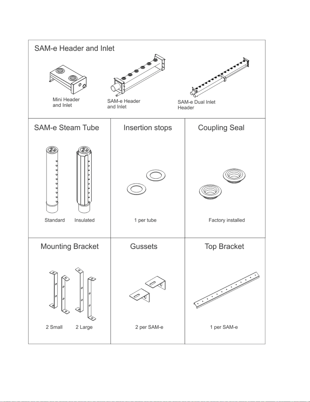
Identify your Components
3 | SAM-e Installation
Page 7
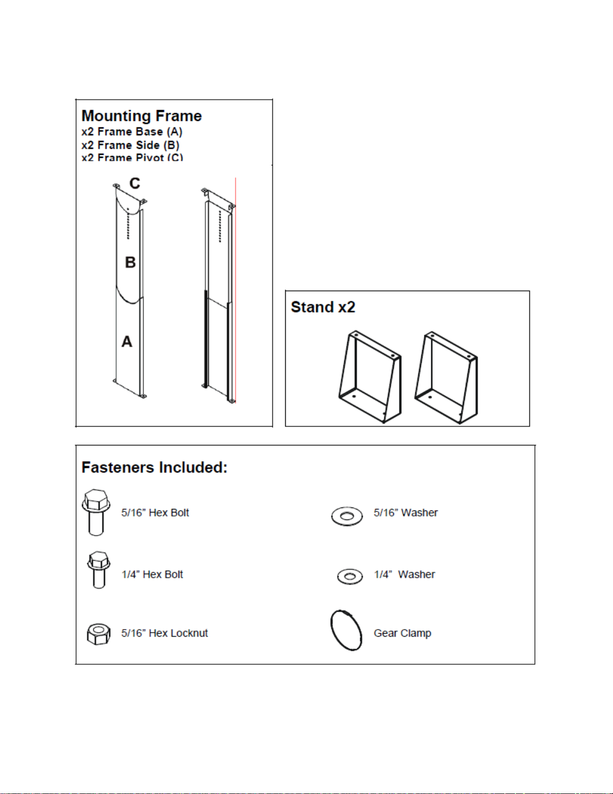
Identify your Optional Components
SAM-e Installation | 4
Page 8
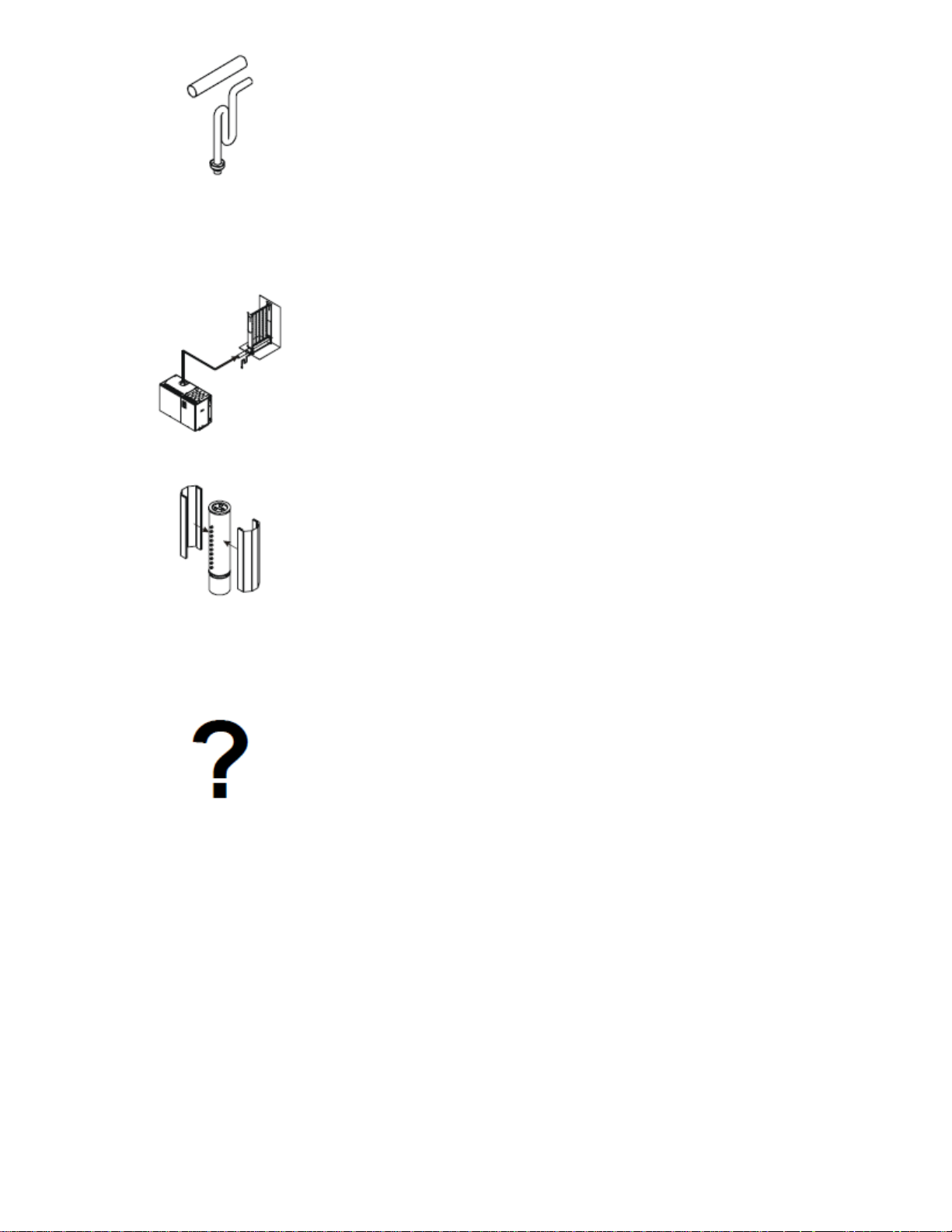
How to Use this Manual
SAM-e - In Duct
Section 2
Follow steps 1-9
SAM-e - Vertical Duct Installation
Section 4
Follow steps 1-8B
Then refer to Section 3.
mini SAM-e
Section 5
Follow steps 1-5
5 | SAM-e Installation
Page 9
Plumbing
Section 6
6A - SAM-e Pressure Steam
6B - mini SAM-e Pressure Steam
6C - SAM-e Atmospheric Steam
6D - mini SAM-e Atmospheric Steam
Steam Lines
Section 7
SAM-e Insulation
Section 8
8A - SAM-e Retrofit
8B - mini SAM-e Retrofit
Troubleshooting, Spare Parts & Warranty
Section 9
SAM-e Installation | 6
Page 10

SAM-e In-Duct
7 | Installation
Page 11
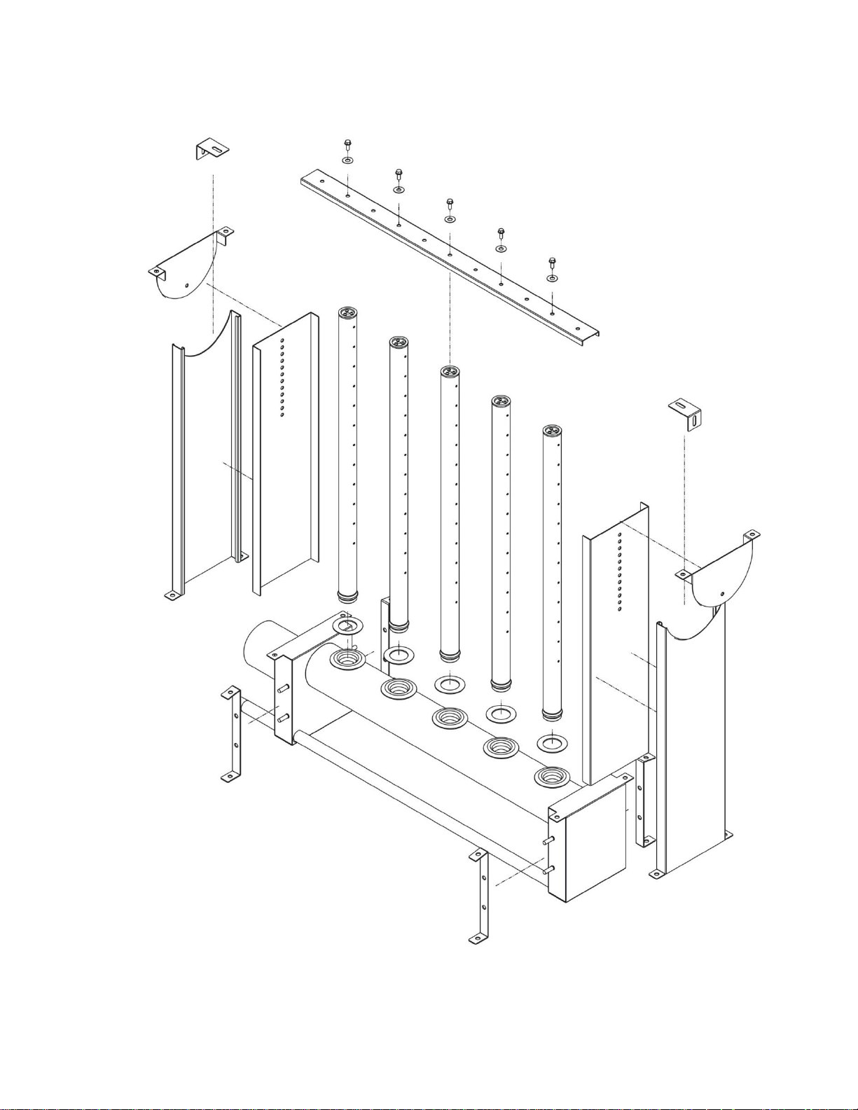
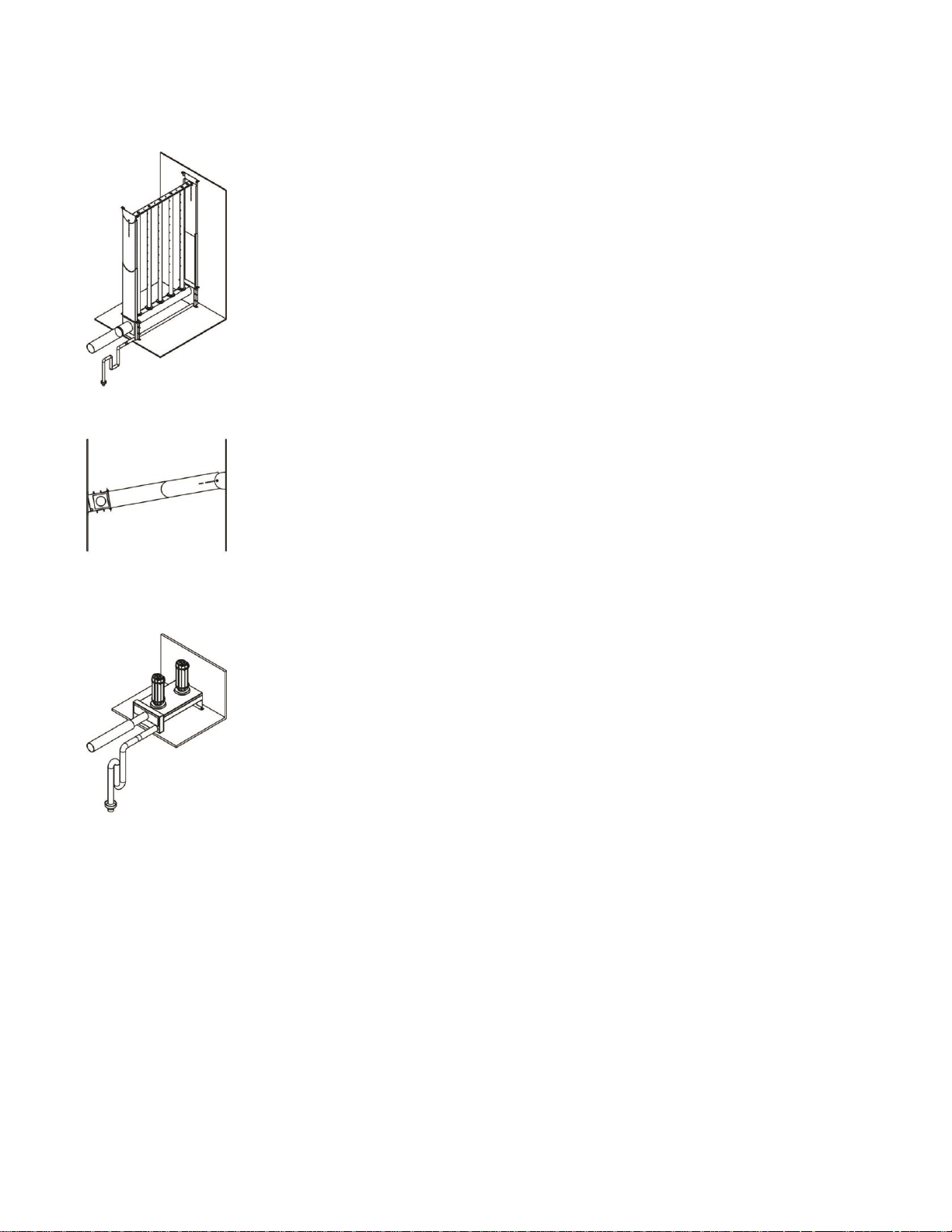
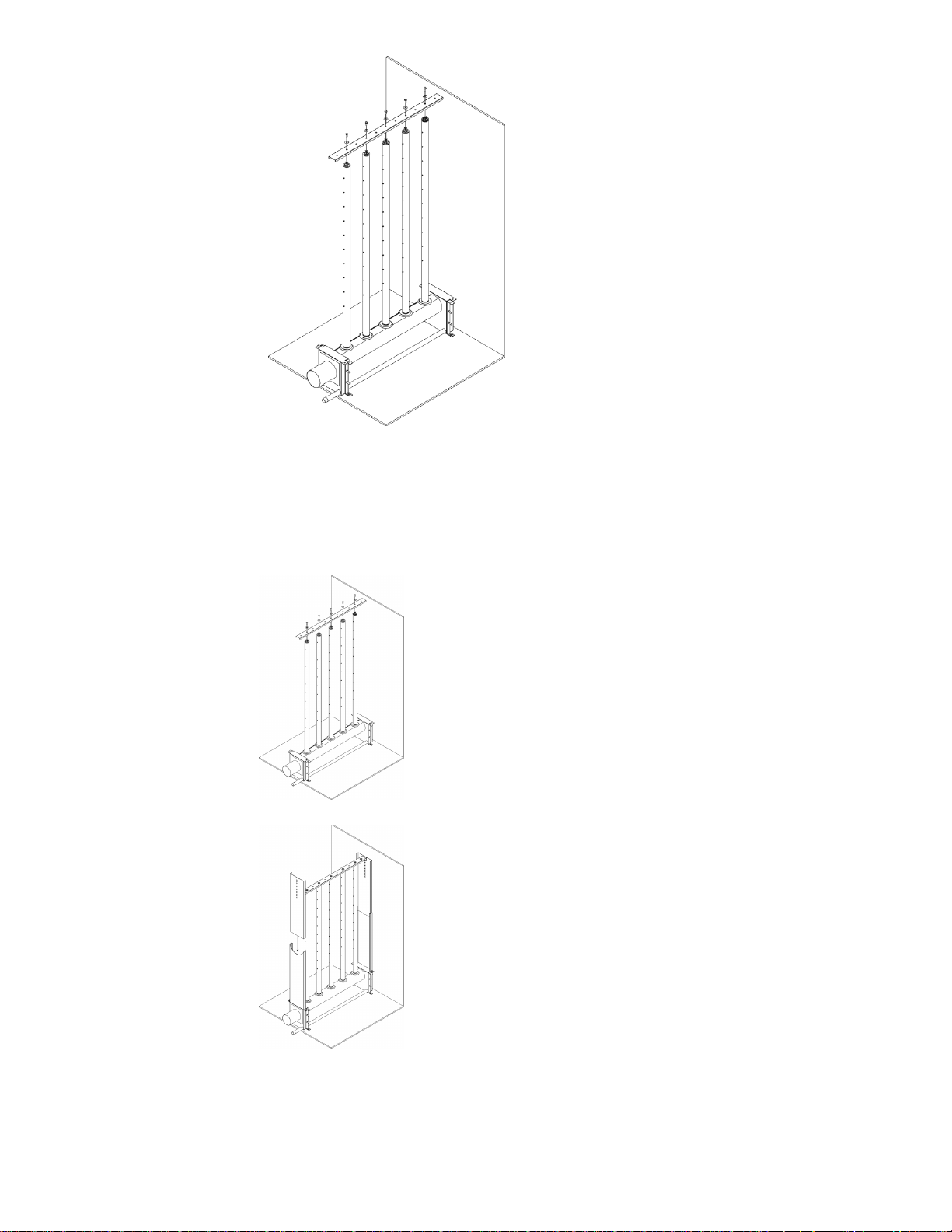
General SAM-e Assembly Diagram
Typical SAM-e Installation
SAM-e Installation | 8
Page 12
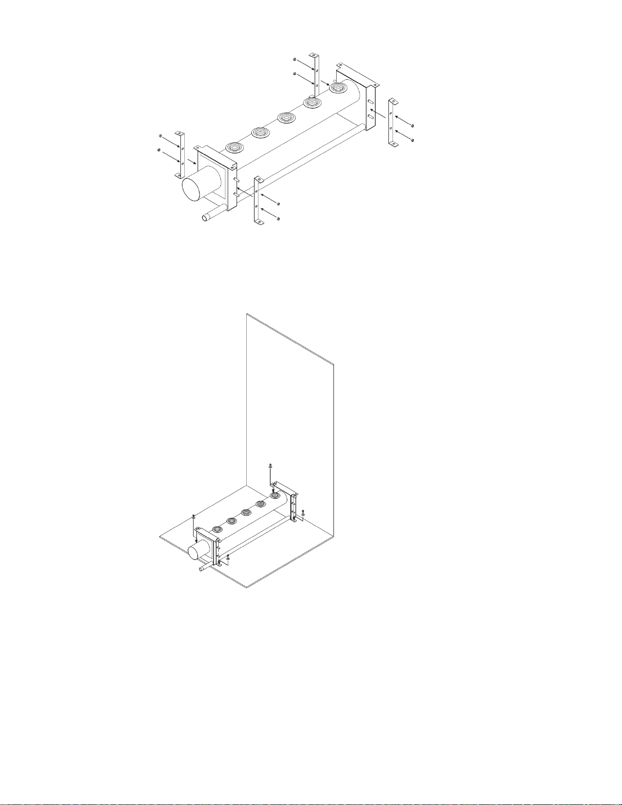
1
Fasten support brackets to header using 5/16” washers and 5/16” nylon lock-nuts.
2
Place header on duct floor and drill 4 x 1/2” (12.7 mm) holes through floor.
Secure header to floor using fasteners (by others).
Use caulking to seal holes in ductwork.
9 | SAM-e Installation
Page 13
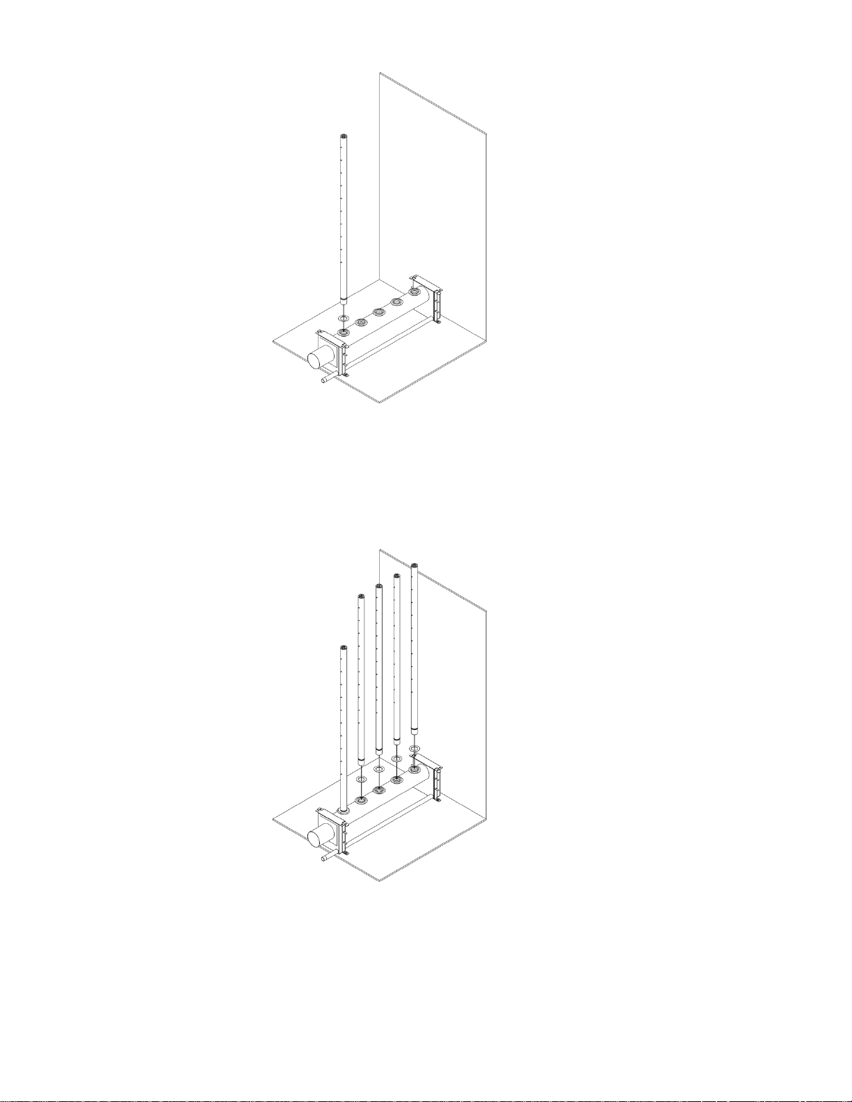
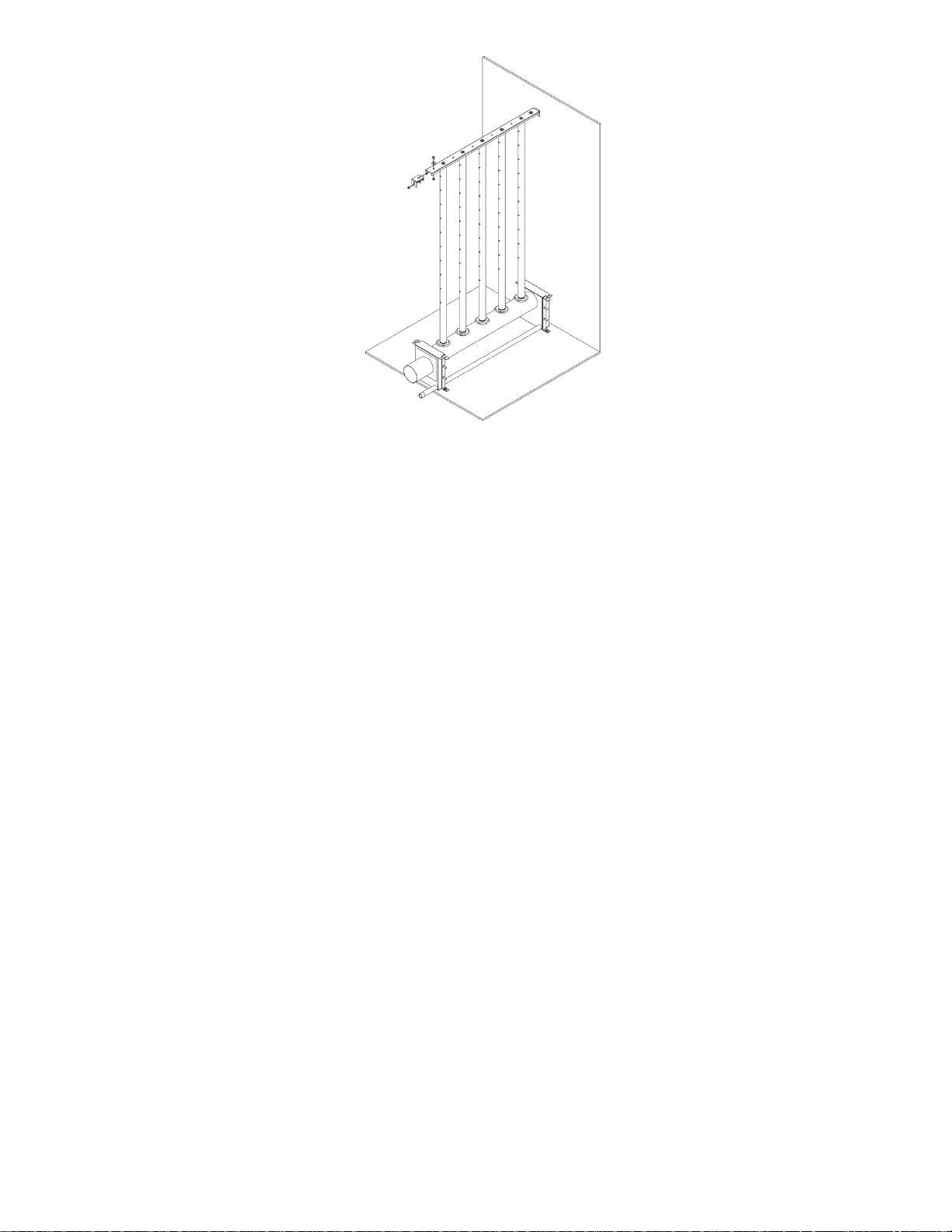
3
Insert tube into insertion stop washer and then into grommet.
Wetting grommet with water will make assembly easier.
Ensure nozzles face the sides of the duct (perpendicular to air flow).
4
Assemble remaining tubes in same way.
SAM-e Installation | 10
Page 14
5
Attach tube support bracket using supplied 1/4” lock-washer and 1/4” hex
screws.
6
No mounting frame –
proceed to step 6A.
Mounting frame –
proceed to step 7
11 | SAM-e Installation
Page 15
6A
If no mounting frame is supplied:
Attach bracket flanges to tube support bracket using 5/16” screws,
washers, and nylon lock-nut.
Bolt flanges to duct wall using field-supplied 1/2”-fasteners.
SAM-e Installation | 12
Page 16
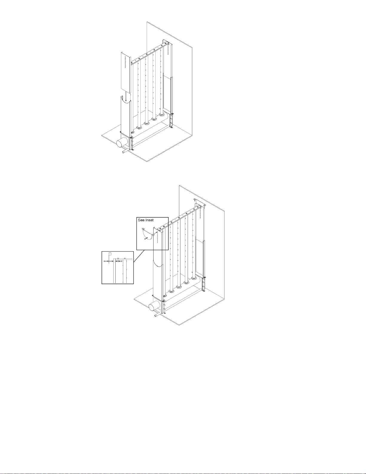
7
Slide frame sides into frame base.
8
Attach Frame Pivot using 5/16” bolt, washer, and nylon lock-nut.
Side View
13 | SAM-e Installation
Page 17

SAM-e Installation | 14
Page 18

Installation in
Vertical Duct
15 | SAM-e Installation
Page 19
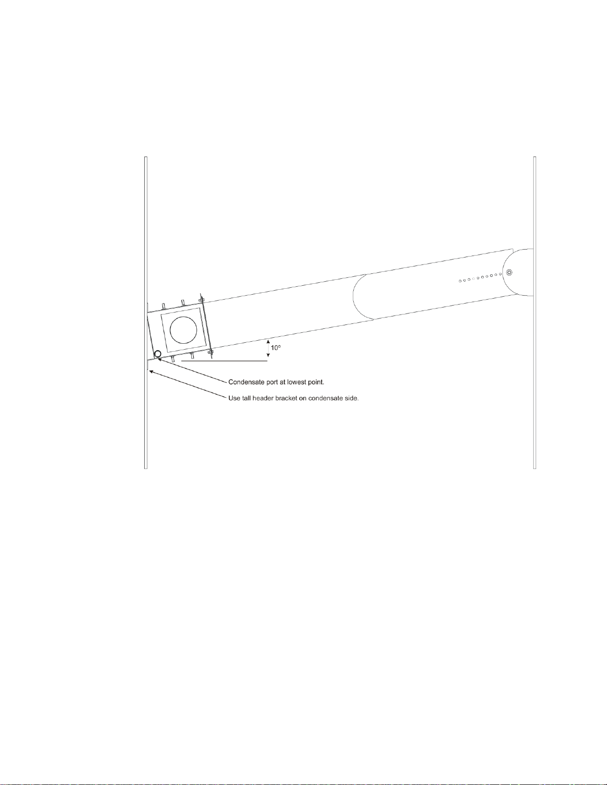
1
Complete assembly following Steps 1 through 8 on pages 9
through 13.
Install complete assembly into duct at 10° angle. Fasten to
duct walls using field-supplied fasteners.
SAM-e Installation | 16
Page 20

Mini SAM-e
Installation Procedures
17 | SAM-e Installation
Page 21

Mini SAM-e Assembly General Installation
SAM-e Installation | 18
Page 22

1
Place header into duct. Use supplied template to cut
holes for steam and condensate parts. Attach
header to duct using field-supplied fasteners.
2
Insert steam tubes with Insertion stop washers,
ensuring nozzles are perpendicular to airflow. Using
water to wet the rubber grommets will facilitate
installation. Seal all ductwork.
19 | SAM-e Installation
Page 23

SAM-e Installation | 20
Page 24

Plumbing
21 | SAM-e Installation
Page 25

• Steam components in grey provided by Nortec.
• Tap steam from top of pressurize steam main to avoid excess condensate.
• Condensate from separator to be returned to pressurized condensate main.
• Condensate from SAM-e to be returned to atmospheric floor drain.
When pressurized steam enters SAM-e, pressure drops down to almost atmospheric pressure.
Therefore, it must be drained atmospherically, and the use of a condensate pump (rated for 212ºF)
must be used to raise condensate to a higher elevation.
Strainer
Manual Shut-Off
Valve (By Others)
Pressurized
Steam Main
F & T Steam Trap
Duct/AHU Width
Duct/AHU
Height
Separator
Actuator & Valve
Pressurized condensate
return main
1” Air Gap
Drain
Manual Shut-Off
Valve (By Others)
6” min.
6” Min
Return to non-pressurized
condensate return main
Tap steam from top of
pressurized steam main
SAM-e with Pressure Steam
Pressurized Plumbing with External Separator
SAM-e Installation | 22
Page 26

Note: The SAM-e header functions as a steam separator, therefore an external steam
separator is not required.
• Steam components in grey provided by Nortec.
• Tap steam from top of pressurize steam main to avoid excess condensate.
• Condensate from SAM-e to be returned to atmospheric floor drain.
When pressurized steam enters SAM-e, pressure drops down to almost atmospheric pressure.
Therefore, it must be drained atmospherically, and the use of a condensate pump (rated for 212ºF)
must be used to raise condensate to a higher elevation.
1” Air Gap
Drain
Strainer
Manual Shut-Off
Valve (By Others)
Pressurized
Steam Main
6” min.
Return to non-pressurized
floor drain
Pressurized condensate
return main
Tap steam from top of
pressurized steam main
Pressurized Plumbing without External Separator
23 | SAM-e Installation
Page 27

Internal Baffle Plate
SAM-e Installation | 24
Page 28

Condensate Pump Plumbing
When pressurized steam enters SAM-e, pressure drops down to almost atmospheric pressure.
Therefore, it must be drained atmospherically, and the use of a condensate pump (rated for 212ºF)
must be used to raise condensate to a higher elevation, or return to a pressurized condensate main.
6” min.
Condensate Pump
(By Others)
Pressurized Steam from Valve
Pressurized Condensate Main
25 | SAM-e Installation
Page 29

• Steam components in grey provided by Nortec.
• Tap steam from top of pressurize steam main to avoid excess condensate.
• Condensate from separator to be returned to pressurized condensate main.
• Condensate from SAM-e to be returned to atmospheric floor drain.
When pressurized steam enters SAM-e, pressure drops down to almost atmospheric pressure.
Therefore, it must be drained atmospherically, and the use of a condensate pump (rated for 212ºF)
must be used to raise condensate to a higher elevation.
Strainer
Manual Shut-Off
Valve (By Others)
Steam Main
F & T Steam Trap
Separator
Actuator & Valve
Pressurized condensate
return main
1” Air Gap
Drain
Steam from top of main
Manual Shut-Off
Valve (By Others)
6” min.
6” min
Return to non-pressurized
condensate return main
Duct Width
Duct
Height
Duct Floor
Mounting
bracket
Mini SAM-e with Pressurized Steam
Mini SAM-e Pressurized with External Separator
SAM-e Installation | 26
Page 30

• Max steam pressure of 15 psig when no separator is used.
• Steam components in grey provided by Nortec.
• Tap steam from top of pressurize steam main to avoid excess condensate.
• Condensate from separator to be returned to pressurized condensate main.
• Condensate from SAM-e to be returned to atmospheric floor drain.
When pressurized steam enters SAM-e, pressure drops down to almost atmospheric pressure.
Therefore, it must be drained atmospherically, and the use of a condensate pump (rated for 212ºF)
must be used to raise condensate to a higher elevation.
Strainer
Manual Shut-Off
Valve (By Others)
Steam Main
1” Air Gap
Drain
Steam from top of main
6” min.
Return to non-pressurized
condensate return main
Pressurized condensate
return main
Mini SAM-e Pressurized without External Separator
27 | SAM-e Installation
Page 31

When pressurized steam enters Mini SAM-e, pressure drops down to almost atmospheric pressure.
Therefore, it must be drained atmospherically, and the use of a condensate pump (rated for 212ºF)
must be used to elevate condensate to a higher point.
6” min.
Condensate Pump
(By Others)
Pressurized condensate
return main
Pressurized Steam
from Valve
Mini SAM-e Condensate Pump Plumbing
SAM-e Installation | 28
Page 32

Atmospheric steam inlet
Use Nortec supplied steam
hose and gear clamps
Drain
1" Air Gap To Prevent
Back Siphonage
6” min.
8” min.
2” plus duct
static pressure
Or
From Humidifier
SAM-e with Atmospheric Steam
Atmospheric Plumbing
29 | SAM-e Installation
Page 33

1" NPT to 3/4” NPT
Reducer
(Supplied By Others)
1" Air Gap To Prevent
Back Siphonage
Atmospheric steam inlet
Use Nortec supplied steam
hose and gear clamps
To drain
1/2” NPT Cold water inlet
3/4” NPT
Manual dump valve
6” min.
8” min.
2” plus duct
static pressure
Or
2” NPT Tempered
Water Drain
Plumbing with Drain Water Cooler
SAM-e Installation | 30
Page 34

Atmospheric steam inlet
Use Nortec supplied steam
hose and gear clamps
Drain
1" Air Gap To Prevent
Back Siphonage
6” min.
8” min.
2” plus duct
static pressure
Or
From Humidifier
Mini SAM-e with Atmospheric Steam
Mini SAM-e with Atmospheric Steam
31 | SAM-e Installation
Page 35

SAM-e Installation | 32
Page 36

Atmospheric Steam Lines
33 | SAM-e Installation
Page 37

Plumbing
Pressurized SAM-e
For pressurized steam line installation instructions, refer to LiveSteam Steam Injection
Humidifier Installation Manual.
Atmospheric SAM-e Steam Lines
Guidelines
1 Nortec steam hose should only be used on short steam runs of less than 10 feet.
2 Ensure that no condensate produced in steam line will remain trapped. Steam naturally
flows upward and condensate naturally flows downward.
3 See material recommended for use in below chart. To eliminate metal corrosion, Nortec
does not recommend the use of steel piping.
4 Consult below charts for steam and condensate sizing guidelines when using steam
distributors.
5 Be sure to include fitting equivalent lengths in total steam run lengths (see below).
In general, match steam-line size to outlet size of distributor.
When using an SETC with less than 15 psig steam supply pressure, a reducer (Nortec part
number 2526110 – 3” to 1.5” reducer or 2526111 – 4” to 3” reducer) is required to
prevent over-sizing of steam lines.
All steam lines should be insulated with at least 1”-thick steam insulation.
SAM-e Installation | 34
Page 38

Table 1: Electrode Steam-Line
Humidifier
Steam
output
[ lb ]
MED-L copper
tube nominal
steam line size
Stainless steel
tube diameter
(wall thickness
0.065”)
Steam loss per
foot in
condensation
[ lb/ft ]
Steam line
maximum
equivalent
length
RH Duct 120V
5
3/4"
7/8”
0.06
8 ft
RH Duct 240V
10
3/4"
7/8”
0.06
15 ft
NH 005
5
3/4"
7/8”
0.06
7 ft
NH 010
10
3/4"
7/8”
0.06
12 ft
NH 020
20
3/4"
7/8”
0.06
17 ft
NH 030
30
3/4"
7/8”
0.06
22 ft
NH 050
50
1-1/2”
1-3/4"
0.11
43 ft
NH 075
75
1-1/2”
1-3/4"
0.11
47 ft
NH 100
100
1-1/2”
1-3/4"
0.11
50 ft
NH 150 (2 outlets)
150
2 x 1-1/2”
1-3/4"
0.11
47 ft
NH 200 (2 outlets)
200
2 x 1-1/2”
1-3/4"
0.11
50 ft
Electrode Steam-Line
• Based on 3” duct static pressure.
• Maximum duct static pressure for electrode steam units is 6” w.c.
• A fill cup extension kit can be used on NH to overcome higher duct static pressure, or for
longer steam line runs. (Consult factory).
35 | SAM-e Installation
Page 39

Table 2: Gas Steam-Line
Humidifier
Steam
output
[ lb ]
MED-L copper
tube nominal
steam line size
Stainless steel
tube diameter
(wall thickness
0.065”)
Steam loss per
foot in
condensation
[ lb/ft ]
Steam line
maximum
equivalent
length
GS 100
100
1-1/2”
1-3/4”
0.11
90 ft
GS 200
200
3”
3”
0.16
90 ft
GS 300
300
3”
3”
0.16
180 ft
GS 400
400
4”
4”
0.22
180 ft
GS 500
500
4”
4”
0.22
220 ft
GS 600
600
4”
4”
0.22
260 ft
Gas Steam-Line
• Based on 3” duct static pressure.
• Maximum duct static pressure for GS is 12” w.c.
SAM-e Installation | 36
Page 40

Table 3: SE Steam-Line
Unit
No. of
Steam
Outlets
Steam
output
[ lb ]
MED-L copper
tube nominal
steam line size
Stainless steel
tube diameter
(wall thickness
0.065”)
Steam loss
per foot in
condensation
[ lb/ft ]
Steam line
maximum
equivalent
length
SE 050
1
50
1-1/2”
1-3/4”
0.11
37 ft
SE 100
1
100
1-1/2”
1-3/4”
0.11
90 ft
SE 175
1
175
3”
3”
0.16
90 ft
SE 250
1
250
3”
3”
0.16
180 ft
SE 375
1
375
4”
4”
0.22
180 ft
SE 575
1
575
4”
4”
0.22
220 ft
SE 750
2
750
2 x 4”
2 x 4”
0.44
260 ft
SE 1050
2
1050
2 x 4”
2 x 4”
0.44
260 ft
SE Steam Line
• Based on 3” duct static pressure.
• Maximum duct static pressure for SE is 12” w.c.
37 | SAM-e Installation
Page 41

Table 4: SE Steam-Line
Humidifier
Steam
output
[ lb ]
MED-L copper
tube nominal
steam line size
Stainless steel
tube diameter
(wall thickness
0.065”)
Steam loss per
foot in
condensation
[ lb/ft ]
Steam line
maximum
equivalent
length
NHRS 010
10
1-1/2”
1-3/4”
0.11
12 ft
NHRS 015
15
1-1/2”
1-3/4”
0.11
15 ft
NHRS 020
20
1-1/2”
1-3/4”
0.11
18 ft
NHRS 030
30
1-1/2”
1-3/4”
0.11
27 ft
NHRS 045
45
1-1/2”
1-3/4”
0.11
43 ft
NHRS 065
65
1-1/2”
1-3/4”
0.11
47 ft
NHRS 090
90
1-1/2”
1-3/4”
0.11
48 ft
NHRS 135
135
2 x 1-1/2”
2 x 1-3/4”
0.11
47 ft
NHRS 180
180
2 x 1-1/2”
2 x 1-3/4”
0.11
48 ft
NHRS Steam-Line
• Based on 3” duct static pressure.
• Maximum duct static pressure for resistive element units is 6”w.c.
SAM-e Installation | 38
Page 42

Table 5: Effective length of Typical Steam-Line Fittings
Nominal tube
size
Standard
90°-elbow
Standard
45°-elbow
Side-outlet
tee
Gate valve*
Globe valve*
3/4”
2 ft
1 ft
4 ft
0.4 ft
18 ft
7/8”
2 ft
1 ft
4 ft
0.4 ft
18 ft
1-1/2”
3.5 ft
1.75 ft
7 ft
0.8 ft
34 ft
1- 3/4”
3.5 ft
1.75 ft
7 ft
0.8 ft
34 ft
3”
5 ft
2.5 ft
11 ft
1.1 ft
54 ft
4”
8 ft
4 ft
15 ft
1.6 ft
80 ft
Table 6: Effective length of Typical Steam-Line Fittings
Material
Type
Note
Copper
MED-L Tube
Recommended.
Stainless steel
Tube wall thickness 0.065”
Recommended.
Required for RO/DI water.
Flex-hose
High-temperature rubber
hose
Nortec high-temperature flex-hose recommended only.
Nortec flex-hose to be checked every 5 years.
Other brands of steam hose may:
- Carry odors
- Kink or deform
- Create back-pressure and affect humidifier
performance
Black pipe
Schedule 40
Schedule 40
Not recommended
Oil seeps out.
Rusting.
Health hazard.
Larger pressure drop.
Plastic
-----
Not recommended
Effective Length of Typical Steam-Line Fittings
*Valve in full open position.
Material for Steam Lines
39 | SAM-e Installation
Page 43

Atmospheric SAM-e Condensate Drainage
1 SAM-e condensate outlet connection is male 3/4”-NPT.
2 Condensate from SAM-e must be plumbed to a P-trap. Trap must have center-to-center
height of at least 8”, or 2” more than duct static pressure, whichever is greater. Refer to
typical installation drawings.
3 Condensate from P-trap should drain into a funnel with air-gap prior to entering building
drain.
4 Condensate exits at 212°F (100°C). Local codes may require use of a drain water
cooler (Nortec part number 1710020 - electronic drain water cooler or 1710010 – selfactuated drain water cooler). Refer to installation manual that accompanies drain water
cooler for plumbing details.
5 When collecting condensate, ensure that each device has an air-gap prior to entering the
condensate collection system. Failing to incorporate an air-gap may cause backpressure
on SAM-e and result in poor performance.
6 Some humidifiers allow distributor condensate to be returned to the unit. Refer to
humidifier manual for details.
7 For systems using condensate pumps, a P-trap and air-gap are still required at SAM-e
outlet. Never connect SAM-e directly to a pressurized drain line.
SAM-e Installation | 40
Page 44

Use appropriate slope
Figure 1: Slope
Figure 2: Insulate pipe
Figure 3: Condensate Traps
MAIN RULES FOR ATMOSPHERIC STEAM LINES:
Follow recommended materials, size and length (see tables)
Steam Lines and Condensate Returns
Steam lines must be sloped
Condensate must be trapped (Use full-size ‘T’ for traps)
Steam lines must not have any restrictions that could cause back-pressure
Insulate with minimum 1” pipe insulation
41 | SAM-e Installation
Page 45

Figure 4: Distributor Above Humidifier (Copper Steam Line)
Figure 5: Distributor Above Humidifier (Hose)
SAM-e Installation | 42
Page 46

Figure 6: Steam Distributor Below Humidifier (Hose)
Figure 7: Steam Distributor Below Humidifier and Obstruction (Hose)
43 | SAM-e Installation
Page 47

Figure 8: Long Steam Run
SAM-e Installation | 44
Page 48

Atmospheric Steam Lines
45 | SAM-e Installation
Page 49

Insulation
Factory-Installed Insulation
1 Unpack tubes and headers. Inspect tubes to ensure that stainless insulation covers have not
shifted during shipping. Tube covers should not be obstructing nozzles, and should be aligned
with nozzles. Header covers should be aligned with grommets, and not obstructing tube holes.
Cut around drilled holes to create access port in side of duct. This port should be large enough
to accommodate Mini SAM-e.
2 After tubes and headers have been inspected, install tubes and header according to this chapter.
Insert all steam tubes into header such that flanges are flush with rubber gaskets. Rotate steam
tubes, as needed, to ensure all nozzles are perpendicular to airflow. Do not lift manifold by steam
tubes.
Field Retrofit of Insulation
1 Unpack insulation covers. Inspect insulating covers for shipping damage; covers should be
straight and all foam strips should be aligned with edge of covers and. After tubes and headers
have been inspected, install tubes and headers according to this chapter. Insert steam tubes
into header, until flanges are flush with rubber gaskets. Rotate steam tubes, as needed, to
ensure all nozzles are perpendicular to airflow. Do not lift manifold by steam tubes.
2 Install tube insulation; each tube shall receive two (2) stainless steel covers and two (2) metal
straps for every four (4) feet of tube length. Fit insulating shields around distributor tubes,
ensuring edges of shields are aligned with nozzles. Secure tubes in place with metal clamps at
top and bottom. Take care to not over-tighten. See Figure 1.
NOTE: Multiple covers may be required to completely insulate SAM-e tube. Please refer to
Table: “Number of Insulating Covers Required to Cover a SAM-e Tube”.
SAM-e Installation | 46
Page 50

Table 7: Quantity of Insulating Covers Required to Cover SAM-e Tubes
SAM-e Tube
Length
[in]
Insulation Length
6 in
12 in
18 in
24 in
30 in
36 in
42 in
48 in
6 2
18
2 24
2
30
2
36
2 42
2
48
2
54
2 60
2 2
66
4
72
2 2
78
4 84
2 2
90
4
96
2 2 102
4
108
2 4
114
6
120
4 2
126
2 4
132
6
138
4
2
Table 8: Quantity of Insulating Covers Required to Cover Mini SAM-e Tubes
Mini SAM-e
Tube Length
[in]
Insulation Length
5 in
7 in
9 in
11 in
13 in
15 in
17 in
19 in
5 2
7
2 9 2
11
2
13
2
15
2
17
2
19
2
21
Quantity of Insulating Covers Required to Cover SAM-e Tube
Quantity of Insulating Covers Required to Cover Mini SAM-e Tubes
47 | SAM-e Installation
Page 51

Header Installation
1 Install header insulation for SAM-e; expand header insulation to fit over header and slide on.
Ensure that edges tuck underneath synthetic grommets on top of header. Secure insulation in
place using metal straps. See Step 2.
2 Install header insulation for SAM-e Dual Inlet; expand insulation to fit over header and slide on.
Additionally, expand smaller metal cover for inlet leg and slide on. If inlet leg insulation conflicts
with inlet adapter, trim insulation to fit. Secure both covers in place with metal strapping. See
Step 3.
3 Install header insulation for Mini SAM-e; expand header insulation to fit over header and slide on.
Take care when installing to avoid permanently bending insulation. Inspect for a tight fit after
installation. See Step 4.
SAM-e Installation | 48
Page 52

1
Install header wrap around header.
2
Tuck header wrap underneath rubber grommets and secure with stainless wraps at
each end.
SAM-e Insulation Retrofit
49 | SAM-e Installation
Page 53

FOR DUAL INLETS; INSULATE HEADER AS SHOWN ON PREVIOUS PAGE.
INSULATE SECOND INLET AS SHOWN
ROLL SHIELD TO
CREATE OVERLAP
DETAIL D
USE TIE WRAP 2538347 TO
SECURE IN PLACE.
D
ALWAYS PLACE TIE WRAPS AT THE
ENDS OFTHE SHILED, 1/2 INCH IN.
WHEN 3 TIE WRAPS ARE NEEDE
POSITION ONE IN THE
APPROXIMATE MIDDLECUT OFF
EXCESS END.TIGHTEN UNTIL
SNUG. DO NOT CRUSH
ORIENT END AS SHOWN
Field Retrofit of Installation Dual Inlet Headers
SAM-e Installation | 50
Page 54

3
Apply shields to tubes and secure with stainless straps.
4
Completed Tube.
51 | SAM-e Installation
Page 55

1
Connect Top and Bottom heat shields together (snap fit) .
2
Completed header.
Mini SAM-e Insulation Retrofit
SAM-e Installation | 52
Page 56

3
Fit shields to tubes.
4
Secure with stainless straps.
53 | SAM-e Installation
Page 57

5
Completed tube.
SAM-e Installation | 54
Page 58

Troubleshooting, Maintenance,
Spare Parts
55 | SAM-e Installation
Page 59

Kit Part #
Kit description
Quantity in Kit
1503812
SAM-e coupling seal for steam tubes (1 per tube)
1
2546662
Insertion stop (1 per tube) (Galvanized)
10
2578156
Insertion stop (1 per tube) (Stainless Steel)
10
2546665
5/16” Locknuts, bolts, washers (Galvanized)
10
2546668
5/16” Locknuts, bolts, washers (Stainless Steel)
10
2546667
1/4" bolts, washers (1 per tube) (Galvanized)
10
2578157
1/4" bolts, washers (1 per tube) (Stainless Steel)
10
2538346
SAM-e insulated tube strapping
1
2538347
SAM-e insulated header strapping
1
2538344
SAM-e insulated dual-inlet header strap (for second inlet)
1
Troubleshooting
Steam tubes discharge water:
1 Steam supply pipe is not insulated.
2 Steam supply pipe not properly drained or sloped.
3 Manifold or adapter condensate drain is clogged or malfunctioning.
4 Excessive back-pressure in condensate drain pipe (due to pressure in secondary condensate
drain); must be piped to non-pressurized condensate return.
5 Primary and secondary condensate drains are both joined together.
6 Condensate line has been routed too high (causing static back pressure).
Maintenance
Inspect SAM-e at start-up.
1 For humidifier maintenance schedule, refer to Installation, Operation, and Maintenance
Manual for your humidifier.
Spare Parts
SAM-e Installation | 56
Page 60

Page 61

Warranty
Nortec Humidity Inc. and/or Nortec Humidity Ltd. (hereinafter collectively referred to as THE
COMPANY), warrant for a period of ten years after installation, that THE COMPANY’s
manufactured and assembled products, not otherwise expressly warranted (with the exception
of the tube coupling seals, two years only), are free from defects in material and workmanship.
No warranty is made against corrosion, deterioration, or suitability of substituted materials used
as a result of compliance with government regulations.
THE COMPANY’s obligations and liabilities under this warranty are limited to furnishing
replacement parts to the customer, F.O.B. THE COMPANY’s factory, providing the defective
part(s) is returned freight prepaid by the customer. Parts used for repairs are warranted for the
balance of the term of the warranty on the original humidifier or 90 days, whichever is longer.
The warranties set forth herein are in lieu of all other warranties expressed or implied by law. No
liability whatsoever shall be attached to THE COMPANY until said products have been paid for in
full and then said liability shall be limited to the original purchase price for the product. Any
further warranty must be in writing, signed by an officer of THE COMPANY.
THE COMPANY’s limited warranty on accessories, not of the companies manufacture, such as
controls, humidistats, pumps, etc. is limited to the warranty of the original equipment
manufacturer from date of original shipment of humidifier.
THE COMPANY makes no warranty and assumes no liability unless the equipment is installed in
strict accordance with a copy of the catalog and installation manual in effect at the date of
purchase and by a contractor approved by THE COMPANY to install such equipment.
THE COMPANY makes no warranty and assumes no liability whatsoever for consequential
damage or damage resulting directly from misapplication, incorrect sizing or lack of proper
maintenance of the equipment.
THE COMPANY makes no warranty and assumes no liability whatsoever for damage resulting
from freezing of the humidifier, supply lines, drain lines, or steam distribution systems.
THE COMPANY makes no warranty and assumes no liability whatsoever for equipment that has
failed due to ambient conditions when installed in locations having climates below 14°F (10°C) during January or above 104°F (40°C) during July.
THE COMPANY retains the right to change the design, specification and performance criteria of
its products without notice or obligation.
57 | SAM-e Installation
Page 62

U.S.A.
1860 Renaissance Blvd.
Sturtevant, WI 53177
826 Proctor Avenue
Ogdensburg, NY 13669
CANADA
2740 Fenton Road
Ottawa, Ontario K1T 3T7
TEL: 1.866.NORTEC1
EMAIL: nortec@humidity.com
WEBSITE: www.humidity.com
 Loading...