

Page 1
Important: Read and save these instructions. This guide to be left with equipment owner.
2568051-F| 28 OCT 2014
RH2+
Installation and
Operation Manual
Includes installation, operation
maintenance and troubleshooting
information for your RH2+ Electric
Steam humidifier
Page 2

INSTALLATION DATE (MM/DD/YYYY)
MODEL #
SERIAL #
CYLINDER #
Thank you for choosing Nortec.
Proprietary Notice
This document and the information disclosed herein are proprietary data of Nortec Humidity Ltd. Neither this
document nor the information contained herein shall be reproduced, used, or disclosed to others without the
written authorization of Nortec Humidity Ltd., except to the extent required for installation or maintenance of
recipient’s equipment.
Liability Notice
Nortec does not accept any liability for installations of humidity equipment installed by unqualified personnel or
the use of parts/components/equipment that are not authorized or approved by Nortec.
Copyright Notice
Copyright 2014, Nortec Humidity Ltd. All rights reserved.
Page 3

Contents
1 Introduction
2 Receiving and Unpacking
3 RH2 Models
4 Options and Accessories
5 Installation
35 Humidifier Schematic
36 How the Humidifier Works
38 Humidifier Configuration
40 Maintenance and
Servicing
6 Typical RH2 Installation
7 Location
8 Mounting with Keyholes
9 Plumbing
10 Steam Distributor
12 Steam Lines and Condensate
Return Instructions
16 Electrical
17 External Controls
22 Options and Accessories
23 Start Up
24 Installation Check
25 On/Off or Modulating Operation
26 Start Up Procedure
41 Required Maintenance
45 Extended Shutdown
46 RH2 Maintenance Checklist
47 Troubleshooting
49 General Troubleshooting
51 RH2 Faults
53 RH2 Wiring Diagrams
54 Spare Parts
58 Warranty
27 Nortec Digital Controls
28 RH2 Pre-Start Up Checklist
31 Operation
32 LED Status Lights
32 Selecting a Relative Humidity
Setpoint
33 Humidifier Components
34 Description of Components
Page 4
CAUTION: Servicing
Disconnect main power before any servicing.
The plumbing and electrical compartments contain high voltage components and
wiring. Access should be limited to authorized personnel only.
During and following operation of the humidifier, the steam and components in
contact with the steam such as the blower pack, steam lines, steam distributors,
and condensate lines can become hot and can burn if touched.
Nortec does not accept any liability for installations of humidity equipment
installed by unqualified personnel or the use of parts/components/equipment
that are not authorized or approved by Nortec.
CAUTION: Electrical
All electrical work should be done according to local and national electrical code.
Electrical connection to be performed by a licensed electrician.
CAUTION: Plumbing
Plumbing to be performed by a licensed plumber.
Drain water from humidifier can be very hot. Do not drain to public sink.
All plumbing work should be done according to local plumbing code.
CAUTION: Installation
Do not mount on hot surfaces.
Do not mount in area where freezing can occur.
Do not mount on vibrating surface.
Do not mount on floor.
The RH2 produces steam at atmospheric pressure. No devices which could block
steam output should be connected to the steam outlet.
Steam lines must be installed so that no restriction can produce backpressure in
the humidifier.
Regardless of selecting on/off or modulating control method, Nortec humidifiers
must have a closed circuit across its on/off security loop control terminal to
operate. Nortec highly recommends the use of a high limit humidistat.
Introduction
1 | Introduction
Page 5
MADE IN CANADA
MODEL:
VOLTS 1:
F.L.A:
KW:
XXXXXXXXXXXXXXXXXXXXXXXX S/N:XXXXXXX
XXXXXX XXX
PHASE:XXXX HZ:
XXXXX
XXXXXX
DATE:
XXXXXXXXX
VOLTS 3: XXXXXX XXX
VOLTS 2: XX XXXX XXX
F.L.A:XXXXX
F.L.A:XXXXX
XXXXXX
XXXXXX
KW:
KW:
Receiving and Unpacking
1 Check packing slip to ensure ALL material has been delivered.
2 All material shortages are to be reported to Nortec within 48 hours from receipt of goods.
Nortec assumes no responsibility for any material shortages beyond this period.
3 Inspect shipping boxes for damage and note damages on shipping waybill accordingly.
4 After unpacking, inspect equipment for damage and if damage is found, notify the shipper
promptly.
5 All Nortec products are shipped on a Free-On-Board (FOB) factory basis. Any and all damage,
breakage or loss claims are to be made directly to the shipping company.
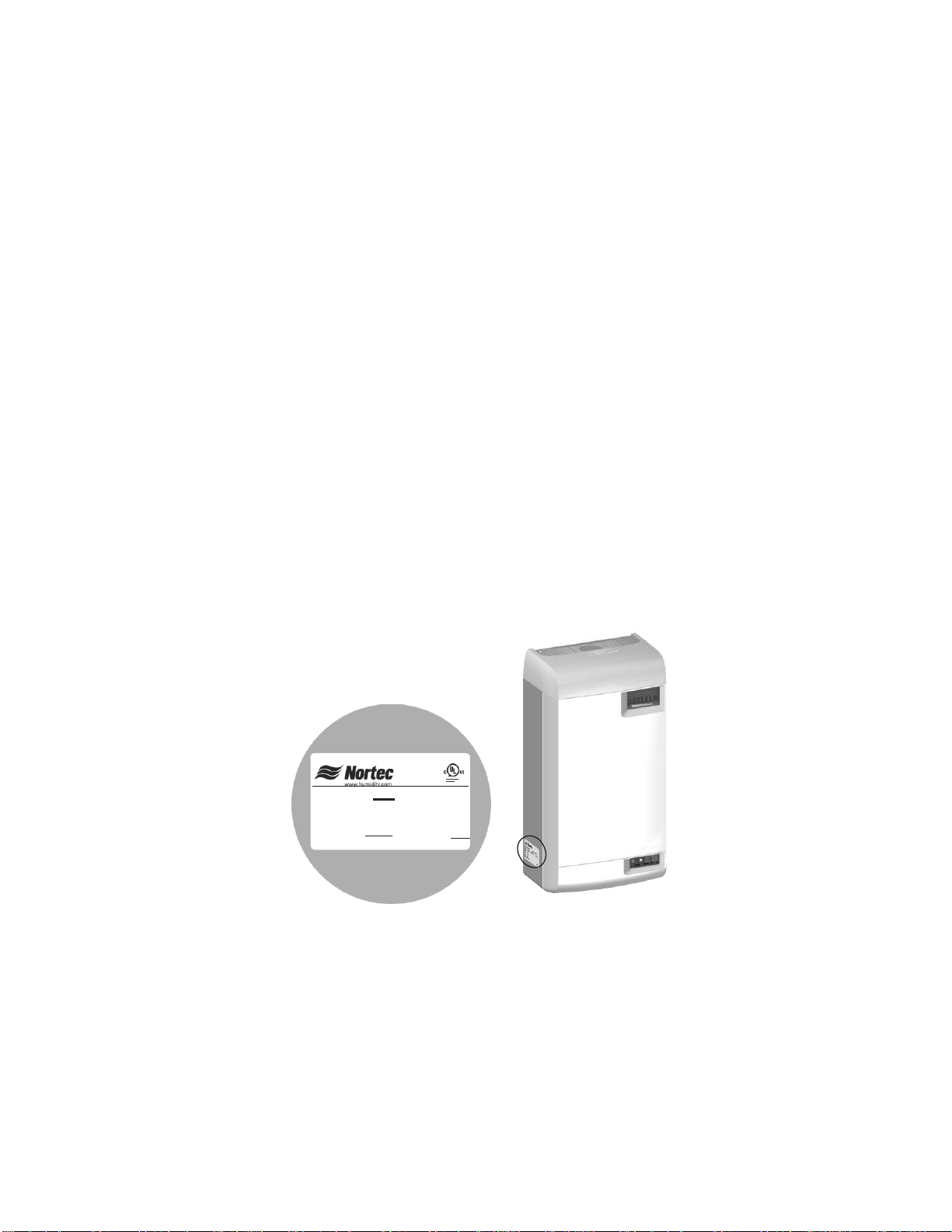
Before Installation
1 Ensure that available voltage and phase corresponds with humidifier voltage and phase as
indicated on humidifier’s specification label.
2 Ensure that the dedicated external fuse disconnect is of sufficient size to handle the rated
amps as indicated on the specification label. Refer to local codes.
3 Report any discrepancy immediately to the site engineer, if applicable.
4 Ensure sufficient clearances will be available as described in the Location section on pg 7.
5 Ensure steam lines can be routed to duct distributor or blower pack as described in Steam
Lines and Condensate Return Instructions on page 12.
Figure 1: Specification Label Location
Introduction | 2
Page 6
Model - Part No.
Volts
Capacity
lb (kg)
KW
Amps
Phase
Max Ext
Fuse
Standard
Cylinder
Net/Full
Weight
lb (kg)
RH2 Space - 2560952
110-120
4 (1.8)
1.5
1
20
202
16 / 22
(7.5 / 10.0)
208
6.9 (3.1)
2.6
12.7
220-240
8 (3.6)
3.0
RH2 Duct - 2560953
110-120
5 (2.3)
1.9
1
20
202
15 / 21
(7.0 / 9.5)
208
8.7 (4.0)
3.3
15.9
220-240
10 (4.6)
3.8
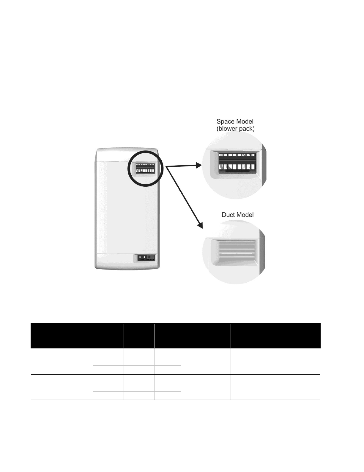
RH2 Models
The RH2 is the most advanced residential steam humidifier available and provides steady and
reliable humidification for a home using the same proven cylinder technology as Nortec’s
industrial electrode platform. The RH2 is available in 2 models: Duct, and Space. The duct
model is designed for connection to a steam distributor installed in a supply air duct, or for
connection to a remote blower pack. The space model is designed for applications where
humidity is to be introduced directly into the conditioned environment. The two models can be
differentiated by the grille in the humidifiers front cover, see Figure 2: RH2 Models.
.
Figure 2: RH2 Models
3 | Introduction
Table 1: RH2 Specifications
Page 7

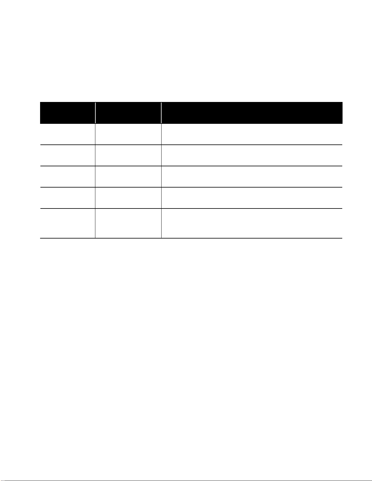
Option / Accessory
Application
Steam Distributors
Introducing steam into ventilation ducts.
Remote Blower Pack
Introducing steam into conditioned environments.
Digital or Modulating Control Humidistats
Controlling the output of the humidifier based on sensed RH.
Digital or Modulating High Limit
Humidistats
Preventing over-humidification in a duct by shutting down or
throttling down the humidifier when RH approaches saturation.
Air Proving Switches
Ensuring humidification only occurs when air is moving in a duct.
Options and Accessories
Nortec provides a complete line of options and accessories for every humidification application.
The following options and accessories are available and may have been delivered with your RH2
humidifier. Refer to the installation instructions that came with the accessories for proper
installation and operation.
Table 2: Options and Accessories
Introduction | 4
Page 8

Installation
6 Typical RH2 Installation
7 Location
8 Mounting with Keyholes
9 Plumbing
10 Steam Distributor
12 Steam and Condensate Returns
16 Electrical
17 External Controls
17 Control Wiring
17 Duct Humidification Control Location
18 Space Humidification Control Location
19 On/Off Control Wiring
20 Modulating Control Wiring
21 Fan Enable Wiring
21 RH2 Fan Control
21 Nortec On/Off Humidistat Fan Control
22 Options and Accessories
22 Remote Blower Pack
5 | Installation
Page 9
2
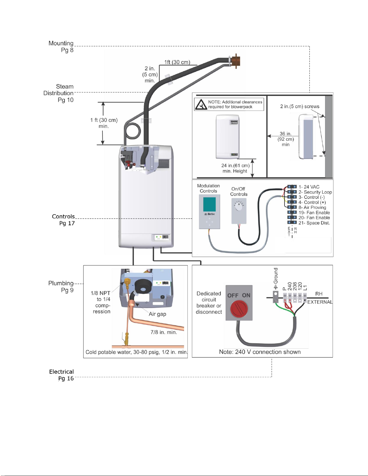
Typical RH2 Installation
Figure 3: Typical Humidifier Installation
Installation | 6
Page 10
Side clearance
for space models
only, see table
36 in. (92 cm)
in. ront learance
duct model
m f c
Additional front clearance
for space models,
see table
24 in.(61 cm)
Min Height
Mount Humidifier
Level
As Close as
Possible to Steam
Distributor
5-95%
Overhead clearance
for space models
only, see table
Humidifier Output lb (kg) Side in. (cm)
<4 (1.8) 12 (30) 12 (30)
6 (2.7) 16 (40) 18 (46)
8 (3.6) 18 (46) 18 (46)
7 ft (2.1 m)
min. Height
for space
models only.
36 (92)
42 (107)
48 (120)
Additional Clearance for Space Models Only
Overhead in. (cm) Front in. (cm)
Note: Do not mount on hot surfaces, where freezing can occur, vibrating surface, or floor.
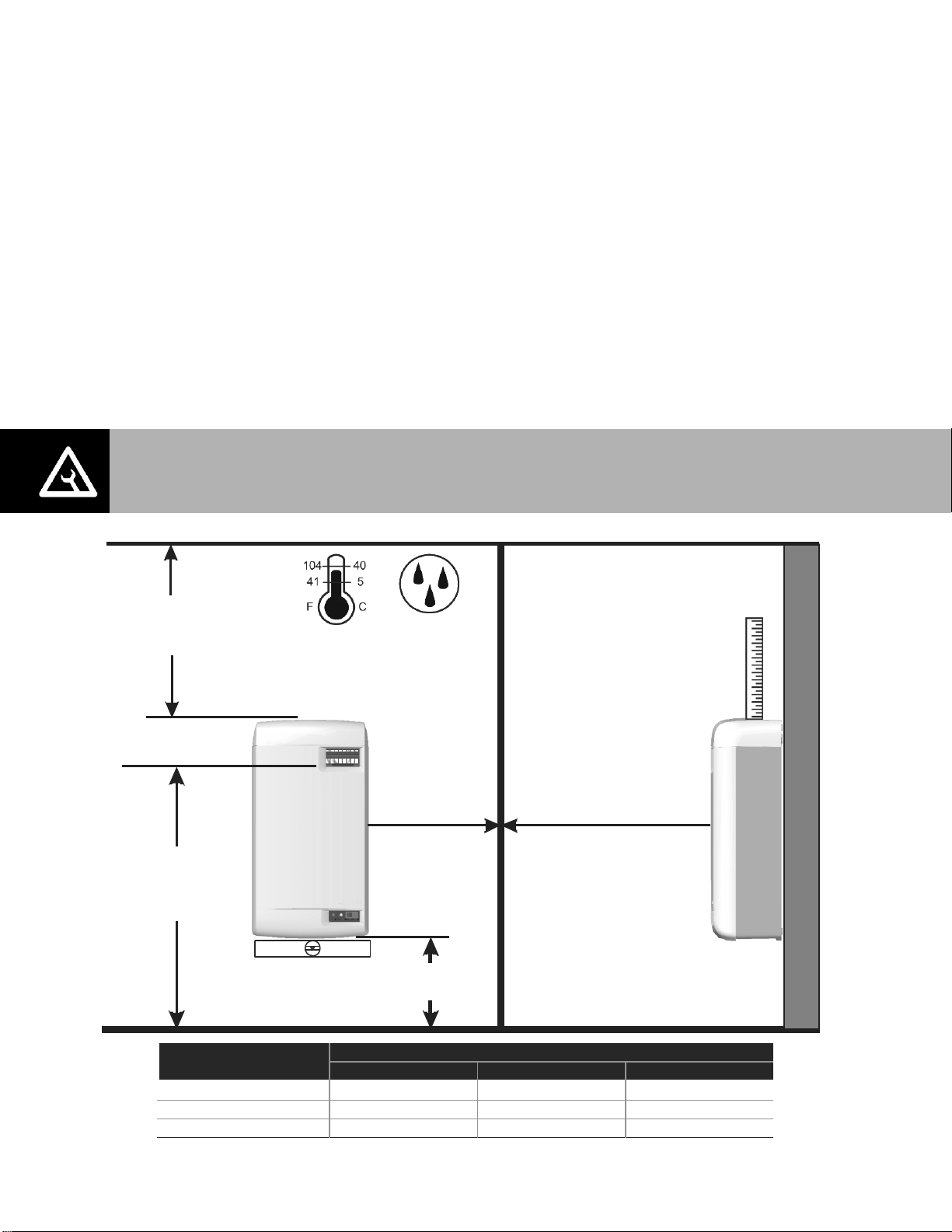
Location
Mount on a suitable wall or vertical surface. Do not sit the unit on the floor. Allow clearances
required for plumbing and electrical connections. Clearance dimensions shown are for
reference only and are the minimum required for maintenance of the humidifier. Consult local
and national codes before final location and installation. Nortec does not accept responsibility
for installation code violations.
Install only in areas with ambient temperature 41-104°F (5 – 40°C) relative humidity
5 - 95%.
When possible install below the steam distributor. Take care to provide proper steam line
routing and proper condensate traps.
DO NOT locate the humidifier any further then absolutely necessary from the steam
distributor location as net output will be reduced as a result of heat loss through the steam
line.
When possible, mount the RH2 humidifier at a height convenient for servicing.
7 | Installation
Figure 4: Mounting Location / Clearance
Page 11
Note: Use screws longer than 2” (5 cm) if drywall or other spacer is present.
Install Second Screw
after hanging
humidifier
#8 x 2 in. (5 cm)
Wood Screws
Insert screw so that
1/4 in. (6 mm) exposed,
hang unit, tighten
screw.
2x4 or Other
Structural
Member
Keyhole
Hole
Mounting with Keyholes
1 The RH2 humidifier is wall mounted using a keyhole located on the back of the unit
cabinetry.
2 Use #8 x 2 in. (5 cm) screws mounted into 2x4 studs or better. 2 screws are needed, one for
hanging the unit and one for securing so it will not lift off the keyhole.
3 Install the top screw so that 1/4 in. (6 mm) is exposed. Raise the unit and place the screw
head through the keyhole.
4 Make sure the unit is level and then insert and tighten the second screw through the bottom
hole. Tighten the top screw. See Figure 5: Mounting With Keyholes.
Figure 5: Mounting With Keyholes
Installation | 8
Page 12
1.2 in. (30 mm). OD
un-threaded outlet
with factory supplied
bent hose and clamp.
Always install a water
shut-off valve.
1/8 in. NPT
Use 1/4 in.
compression
fitting to connect
supply line to
unit.
*Pipe and water shut-off valve not supplied by Nortec.
Use 1/2 in. OD copper to within 4 ft (1.2 m) of humidifier
Note:
1 Fill and drain lines
can also be routed
through opening in
back of cabinet.
2 Optional cover
2548313 Is available
to conceal plumbing
connections.
Air gap required. 2 1/2 in. to 7/8 in.
Copper reducer is ideal. (NORTEC option
P/N 2522172) Hose must not
touch the bottom of the funnel.
Min. 7/8 in. OD drain line.
Keep as short as possible.
Slope down to floor
drain or main drain.
All water supply and drain line connections should be installed in accordance with
local plumbing codes.
Drain water is automatically cooled to 140°F (60°C). Drain material must be
rated for this temperature.
For humidifiers installed in some cities including the City of Los Angeles:
A city-approved spring-loaded double ball CHECK VALVE must be installed by
contractor on the potable water inlet to the humidifier. Recommended valve
manufacturer: Watts Regulator, phone number 508-688-1811, Size depending on
supply line 1/4”, 3/8”, or 1/2” NPT inlet and outlet, Model #7.
Plumbing
Supply water should at 30 to 80 PSIG and be between 150-1200 Microsiemens
(330-670 S optimal range). Consult factory for water conditions outside of this range. Do
not use reverse osmosis or de-ionized water. Supply water should be cold (34-68ºF/1-20ºC).
Install water shut off valve before humidifier to facilitate servicing.
The drain line should not end in a sink used frequently by personnel, or where plumbing
codes prohibit it. Route to a floor drain or equivalent for safety reasons.
Ensure drain line is adequately sized to provide free and easy draining and that an air gap is
installed as shown. A restricted drain can cause cylinder water to over concentrate and
result in poor operation.
Figure 6: Water Supply and Drain Connection
If a drain is not located near the humidifier use a condensate pump rated for hot drain water
such as Nortec’s Part Number 1429527.
9 | Installation
Page 13
Nortec Part
Number
Option Description
Notes
1581820
Nozzle Distributor Kit
Includes a steam distribution nozzle, steam hose, condensate hose,
and installation hardware. See Figure 7.
2553708
RSD 10 Distributor Kit
Includes a steam distributor, steam hose, condensate hose, and
installation hardware. See Figure 8.
Select to duct
dimensions
ASD Duct Distributor
Used when duct width exceeds 12”. Refer to Distributor manual or
HELP software for selection.
Select to duct
dimensions
Mini SAM-e
Used when short absorption is necessary. Refer to SAM-e manual
or HELP software for selection.
2564776
RMBP for RH2 Duct
Remote Mounted Blower Pack, used with the RH2 Duct, adds steam
directly into the space. The blower pack is installed remote to the
humidifier.
Steam Distributor
Steam generated by the RH2 Space is blown directly into the space by the integrated blower
pack. The RH2 Duct requires a steam distributor, installed in the ventilation duct. The RH2
Duct can distribute steam into a ventilation duct using the following distributor options in
Table 3.
Table 3: RH2 Duct Steam Distributor Options
Whichever method is used, the steam distributor should be installed as close as possible to
the humidifier. Short steam distribution lines minimize condensate losses and the
possibility of generating backpressure in the steam distribution line.
Installation | 10
Page 14
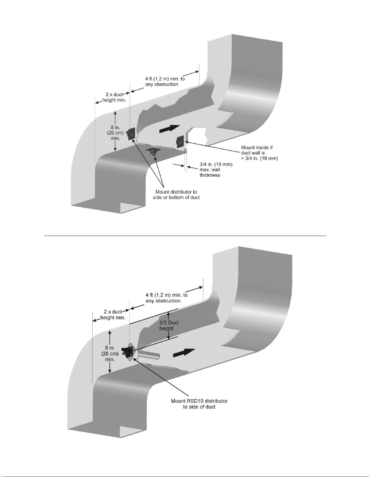
Figure 7: RH2 Duct Nozzle Distributor Installation
11 | Installation
Figure 8: RH2 Duct RSD10 Distributor Installation
Page 15
Voltage
Steam Output
Material*
Maximum
Steam Line
Length
Possible Losses
lbs/hr
(kg/hr)
Nortec Steam
Hose
MED-L
Copper
Tube
Stainless
Steel
Tube
ft
(m)
lbs/hr
(kg/hr)
110-
120V
5
(2.3)
Part Number
1328810
(7/8”)
3/4”
0.875 X
0.049W
7
(2)
0.5
(0.2)
208V
8.7
(3.3)
10
(3) 1 (0.5)
220-
240V
10
(4.6)
12
(3.5)
1.5
(0.7)
Oversized Steam Line (used for longer steam runs)**
110-
120V
Not
Recommended
Not
Recommended
1”
1.125 X
0.049W
Not Recommended
208V
8.7
(3.3)
12
(3.5) 2 (0.9)
220-
240V
10
(4.6)
24
(7) 3 (1.4)
Steam Lines and Condensate Return Instructions
The following instructions must be followed for installation of steam lines for the RH2 Duct.
Failure to use recommended material and exceeding maximum recommended length in Table
4, or failure to follow any other steam line installation instructions will result in improper
operation and could void the warranty.
Table 4: Recommended Steam Line Material for RH2 Duct
Note: * The use of steam line other than copper, stainless steel tube or Nortec supplied steam line will void the warranty and may adversely
affect the operation of the humidifier.
** These diameters require a reducer at humidifier and steam distributor connection. Use Nortec part number 1115444 at
humidifier to prevent backpressure caused by condensation collecting at the reduction.
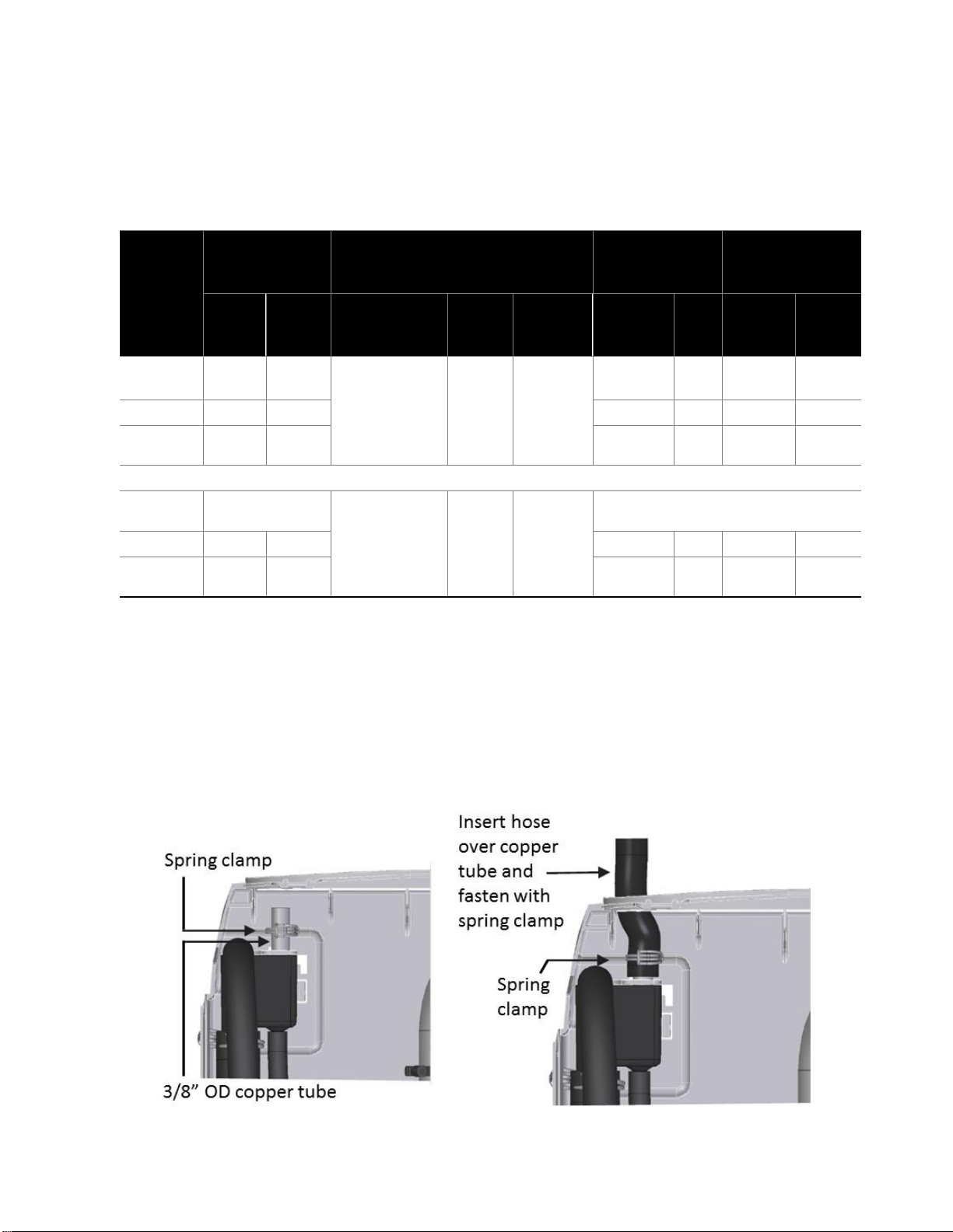
To return condensate for RH2+, insert copper tube (supplied with equipment) half way into the
condensate opening of the fill cup along with the spring clamp (supplied with equipment).
Insert the condensate hose into the condensate return hole at the top of the RH unit, and over
the copper tube. Fasten in place with the spring clamp.
Figure 9: Condensate Return
Installation | 12
Page 16
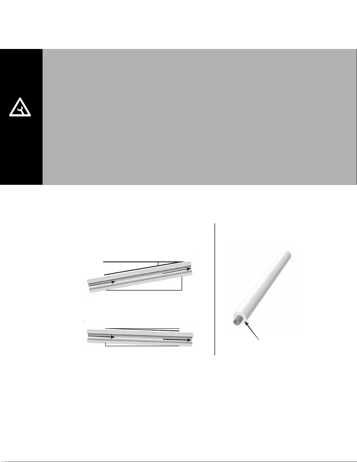
MAIN RULES FOR ATMOSPHERIC STEAM LINES
Steam lines must not have any restrictions which could result in back pressure.
Follow recommended materials, size and length, see tables.
Slope the steam lines.
Insulate with 1.0 in. (2.5 cm) pipe insulation
Trap condensate (Use full size ‘T’ for Traps)
Do not over tighten hose clamp at cylinder steam outlet. The maximum torque is 12
in-lbs.
Support steam line so weight is not on cylinder.
Condensate traps must be a minimum of 6 in. (15 cm) in height or duct static
pressure + 2 in. (5 cm), whichever is greater.
Trapping by P-trap or pigtail. Support line as necessary to ensure it remains free of
kinks.
S
t
eam
Dire
ction
Ste
am
D
ire
c
tio
n
S
t
e
a
m
D
i
r
e
c
t
i
o
n
2 in.
(5 cm)
1 ft (30 cm)
1ft (30 cm)
0.5 in.
(12 mm)
10 Degrees
2 Degrees
Use Appropriate Slope Insulate Pipe
1 in. (2.5 cm) pipe
insulation
Figure 10: Main Steam Line Requirements
13 | Installation
Page 17
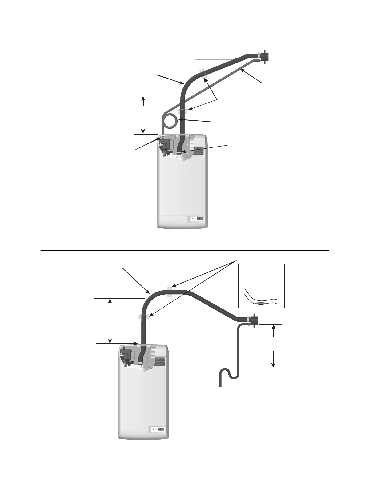
Condensate
Trap
1 ft (30 cm)
min. Before
any bend
Min 12 in.
(30 cm)
radius
Hose will soften
over time
proper support
Is necessary
Support Brackets
1 ft (30 cm)
min.
To Drain
1 ft (30 cm)
min. before
any bend
12 in.(30 cm)
min. Radius
Condensate
Trap
Condensate
line
Connect Steam
Hose to CylinderConnect Condensate
Hose to Fill Cup
2 in. (5 cm)
min.
1 ft (30 cm)
Support
Brackets
Figure 11: Steam Distributor Above Humidifier (Hose)
Figure 12: Steam Distributor Below Humidifier (Hose)
Installation | 14
Page 18
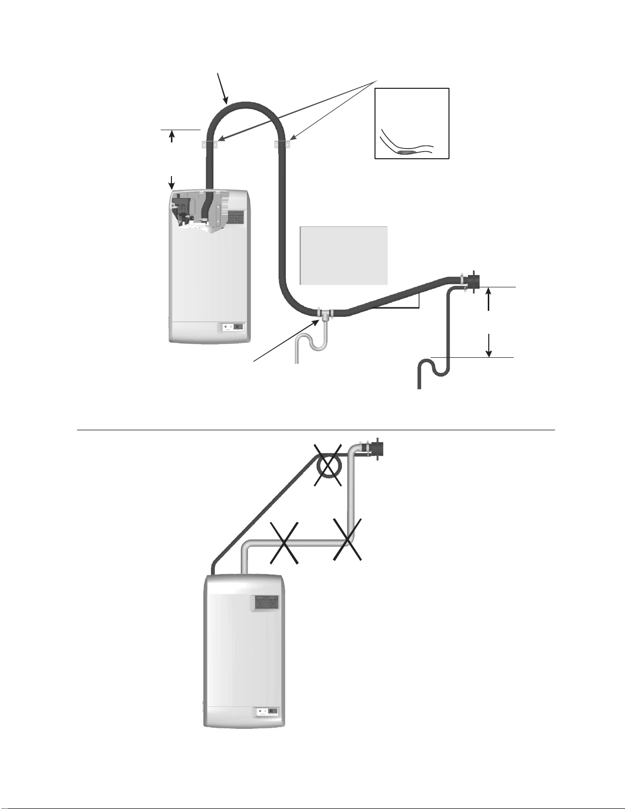
Steam line
not sloped
No condensate
trap at vertical
transition
Condensate trap
not 12 in (30 cm)
below distributor
1ft (30 cm)
min. before
any bend
12 in.
(30 cm)
min.
radius
Obstruction
Use full size condensate tee
at low point. Slope lines up
to “T” and immediately after it.
Hose will soften
over time
proper support
Is necessary
Support brackets
1 ft (30 cm)
min.
To drain
To drain
2 in.
(5 cm)
min.1 ft (30 cm)
Figure 13: Steam Distributor Below Humidifier With Obstruction (Hose)
15 | Installation
Figure 14: Common Steam Line Errors
Page 19
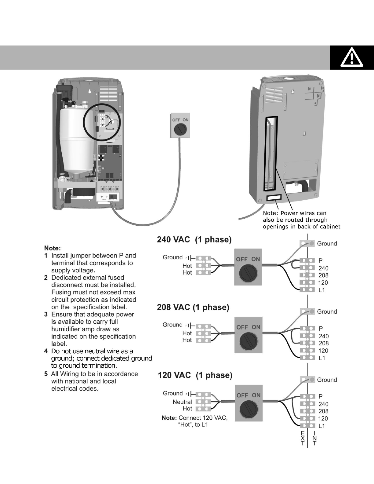
Caution: Wiring to be performed by a licensed Electrician.
Electrical
Figure 15: Primary Power Connection
Installation | 16
Page 20

Caution: Failure to wire the humidifier in accordance with the wiring instructions could
cause permanent damage. Such errors will void the warranty.
External Controls
Control Wiring
Controls are available from Nortec as accessories. If controls were not ordered with humidifier,
they must be purchased or supplied by others. The following information is relevant to all
controls, factory supplied or otherwise. For wiring use minimum 18 AWG and keep as short as
possible.
The RH2 humidifier can be operated with either On/Off controls only or with On/Off controls and
one modulating input. The modulating input can be from a duct high limit or humidity control
humidistat. See Humidifier Configuration on page 38 to configure the RH2 for modulation.
Duct Humidification Control Location
Figure 16: Control Location (Duct Humidification)
Duct Humidification Control Location
1 Air Proving Switch
o Locate upstream so that it can sense air flow or lack of it.
2 Duct High Limit – Can be modulating or On/Off humidistat.
o Locate at least 10 feet downstream from steam distributor or far enough that
under normal conditions steam is fully absorbed.
3 Humidity Control - Can be Modulating or On/Off humidistat
o Can be located either in return air duct (preferred) or in room being humidified.
o Avoid placing near discharge diffuser of humidified air.
o Mount in area representative of room humidity (draft, doorways, sunlight, or
overhang such as a shelf can affect reading).
4 Outdoor Temperature Sensor (not shown)
o Mount outside in area representing air temperature.
17 | Installation
Page 21

Note: Regardless of selecting on/off or modulating control method,
Nortec humidifiers must have a closed circuit across its on/off security
loop control terminal to operate. Nortec highly recommends the use of a
high limit humidistat and an air proving switch in series for this function.
Space Humidification Control Location
These instructions apply to the RH2 Space and the RH2 Duct with Remote Blower Pack.
Figure 17: Control Location (In-Space Humidification)
Space Humidification
1 Humidity Control – Can be Modulating or On/Off humidistat
o Locate in room being humidified but not in discharge zone of blower pack.
o Mount in area representative of room humidity (draft, doorways, sunlight, or
overhang such as a shelf can affect reading).
2 High Limit Humidistat (not shown)
o Install an On/Off High Limit Humidistat in an area representative of room humidity.
3 Outdoor Temperature Sensor (not shown)
o Mount outside in area representing air temperature.
Installation | 18
Page 22

Figure 19: Digital On/Off Humidistat
On/Off Control Wiring
Figure 18: On/Off Controls
19 | Installation
Page 23

Modulating Control Wiring
Figure 20: Modulating Controls
Figure 21: Modulating Control Wiring
Installation | 20
Page 24

Figure 22: RH2 Fan Enable Wiring
Figure 23: Nortec Digital On/Off Humidistat Fan Enable
Fan Enable
Fan Enable Wiring
When distributing steam into a duct, there can be a call for humidity when there is no air flow.
Either the RH2 or the Nortec On/Off digital humidistat can be used to enable a fan on a call for
humidity. Wiring below is for a typical furnace installation. Consult the air handler’s installation
manual for exact wiring instructions on how to enable the fan.
RH2 Fan Control
The RH2 can be used to turn on a furnace fan where there is a demand for humidity without a
call for heat.
*Humidifier will not start producing steam until fan security loop is closed.
Nortec On/Off Humidistat Fan Control
Nortec digital On/Off humdistats include a second dry set of points to enable a fan where there
is a call for humidity without a call for heat.
21 | Installation
Page 25

Note:
The blower pack requires additional clearance see the instructions that came with it.
The steam line slope for the blower pack is 4 in. / 1 ft (10 cm / 30 cm).
Options and Accessories
Remote Blower Pack
A remote blower pack is available for the RH2 Duct for applications where steam for
humidification must be introduced directly into the conditioned environment but the humidifier
must be installed in a different location.
For instructions on installing the remote blower pack, refer to the installation instructions
supplied with it.
The steam line instructions in this manual are also applicable to remote mounted blower
packs except the slope must be larger because the blower pack does not have a separate
condensate line and the maximum allowable steam line length is 4 ft (1.2 m)
Figure 24: Remote Mounted Blower Pack
Installation | 22
Page 26

Start Up
24 Installation Check
25 On/Off or Modulating Operation
26 Start Up Procedure
27 Nortec Digital Controls
27 Modulating Control
27 On/Off Control
28 RH2 Pre-Start Up Checklist
23 | Start Up
Page 27

Installation Check
Before turning on power to the RH2 inspect the installation to ensure that it was carried out
correctly. Refer to RH2 Pre-Start Up Checklist on page 28, and to the Installation chapter.
Figure 25: Installation Check
Start Up | 24
Page 28

Caution: Do not leave the On/Off/Drain switch in the drain position for extended
periods of time. The drain valve solenoid may heat up and result in damage to the
valve and its wiring.
On/Off or Modulating Operation
From the factory the RH2 is configured to operate as an On/Off humidifier. It will run when 24
VAC from terminal 1 is fed back into terminal 2 through an On/Off humidistat and other security
devices in series. See On/Off or Modulating Control (J10) on page 39 for instructions on
configuring the RH2 to operate as a modulating humidifier.
25 | Start Up
Page 29

Note: If operated on low conductivity water it may take several hours for the RH2 to reach
full output capacity. This is normal. During this time the humidifier will not perform any
drains and the conductivity of the water in the cylinder will increase.
Warning: Damaged Units or improperly installed units must not be operated. Damaged or
improperly installed units may present a danger to persons and property.
Note: While the cylinder is filling with water there should be no water flowing down the
drain. If water is flowing down the drain it can indicate excessive backpressure or a
leaking drain valve. See chapter on Troubleshooting.
Start Up Procedure
1 Examine the humidifier and installation for damage and/or improper installation.
2 Ensure the cylinder is properly seated in the drain valve and that the electrode plugs are
pushed all the way down on the cylinder pins.
3 Ensure that the front cover is in place and secured with its retaining screws.
4 Open the supply water shut off valve.
5 Turn on the main power using the installed disconnect.
6 Turn the On/Off switch on the front of the humidifier to On.
The humidifier will perform a self-diagnostic sequence during which the LED’s and internal
components will be momentarily activated. See Figure 27 on page 32 for an explanation of
LED colors and sequences.
If an error is detected during the self-diagnostic sequence the humidifier will not start. The
yellow status LED will flash in sequence to indicate the detected fault. See section RH2
Faults on page 51 for information on diagnosing and correcting faults.
After the system test the humidifier is in normal operation mode.
7 Check and adjust the control setpoint on the control and high limit humidistat.
8 When the external humidistat generates a demand for humidity and the security loop is
closed the green humidifying LED on the front of the humidifier will light up, the power relay
on the control board will engage, the fill valve will activate (after a delay) and the cylinder will
slowly fill with water.
9 If the fan enable relay is used, the green LED will continue to flash until the air proving
closes. Once the air closes, the flashing green LED will become solid and the humidifier will
start steam production as described in step 8.
10 It can take 5 – 10 minutes for the water to be heated up by the submerged electrodes and
for steam to be produced.
Start Up | 26
Page 30

Output signal is shown on
modulating controller
proportional to the demand.
State of On/Off humidistat
Setpoint (RH%)
Humidity (RH %)
Indicates the
humidistat is on.
A half moon
indicates it is off.
Snowflake indicates the
setpoint is being
overridden by outdoor
temperature.
Option button accesses
sensor calibration.
See troubleshooting
Increase / Decrease Setpoint
Power button turns
off the humidiistat if
pressed for 2 seconds
Note: It is possible to field calibrate Nortec digital controls if the displayed humidity is
found to be different than a known trusted source. See chapter on Troubleshooting.
Nortec Digital Controls
Nortec provides optional On/Off and Modulating digital controls. Figure 26 show the function
and meaning of the Digital Control’s display and buttons. All controls are available either wall
mounted or with a remote sensor for duct mounting.
Modulating Control
The modulating controls use a PI control algorithm to transmit a 0-10V control signal to the
humidifier. Adjust the setpoint to the desired setting by using the up/down arrow buttons on
the controller.
On/Off Control
The On/Off controls use a PI control algorithm to open and close a relay that opens and closes
the humidifier’s On/Off loop. Adjust the setpoint to the desired setting by using the up/down
arrow buttons on the controller.
27 | Start Up
Figure 26: Modulating and On/Off Digital Control Operation
Page 31

RH2 Pre-Start Up Checklist
Unit Serial #: _________________ No. of humidifiers: _______ Tag: _______________
Unit type: _______ __________ Voltage: ________V/_____ph
Cylinder type: Customer/Job: Address:
WATER QUALITY:
Well water City water Softened water
HUMIDIFIER MOUNTING:
Level • Front Clearance 36 in.
STEAM LINE(S):
Material • Diameter / Size
Slope up (min 2 in/ft) • Slope down (min 0.500 in/ft)
Low point condensate traps • No hose kinks / Restrictions
Minimum 1 inch insulation
CONDENSATE LINE(S):
P Trap min 6 in or duct press + 2in • P Trap min 12 in drop
WATER LINE:
1/2 in to within 4ft of unit • Water pressure: 30-80 psig
Cold water source (34-68ºF/1-20ºC)
DRAIN LINE:
Air gap within 3 ft of the unit • Diameter / Size
CYLINDER:
Seated in drain valve yes no
Torque for gear clamp of cylinder steam exit to steam line (max 12 in•lbs): ______________
WIRING:
Wiring connections and connectors secured yes no
CONTROLS:
On / Off / Security loop devices working correctly yes no
Jumper J10 set to
Modulating (removed)
Or
On/Off (installed)
Control Location
High Limit Location
POWER:
Voltage, amp, fuse per Spec Label: yes no
Disconnect switch located close to humidifier yes no
Panel Number
Inspected by: Date of inspection: ______/_______/______
Company:
Start Up | 28
Page 32

Note: Most water does not contain enough conductivity for full boil on initial start-up. Units
will need to concentrate the water over a time period (hours to days).
RH2 Start Up Checklist
Unit Serial #: _________________ No. of humidifiers: _______ Tag: _______________
Unit type: _______ __________ Voltage: ________V/______ph
Cylinder Type: Customer/Job: Address:
PRELIMINARY:
Pre-start-up checklist completed? yes no
If no, perform Pre-Start-up Checklist before starting humidifier.
START-UP PROCEDURE:
The prerequisites for the humidifier filling and contactor pulling in to make steam are as follows:
Front cover in place and secured with screws yes no
Water supply valve opened yes no
Mains disconnect switched on yes no
Turn On/Off switch on yes no
On/Off security loop (Terminal 1 and 2) closed. yes no
Fan security (Terminal 1 and 8) closed yes no
CONTROLS:
Installed controls match configuration yes no
Control Setpoint: High Limit Setpoint:
> 3 VDC on terminal 4 (Modulating Humidistat) yes no
or
Terminal 1 and 2 closed (On/Off Humidistat) yes no
The Humidifier will undergo a self-test when the power is turned on activating the LED’s and other
internal components.
If the above listed prerequisites are fulfilled the humidifier will start filling the cylinder and begin
normal operation.
REMARKS:
Started by: Date of Start Up: _______/_______/______
Company:
29 | Start Up
Page 33

Start Up | 30
Page 34

Operation
32 LED Status Lights
32 Selecting a Relative Humidity Setpoint
33 Humidifier Components
34 Description of Components
35 Humidifier Schematic
36 How the Humidifier Works
36 Steam Generation
36 Drains
36 Steam Distribution
37 Steam Line
37 Condensate Return
38 Humidifier Configuration
31 | Operation
Page 35

Yellow LED Steady On
When the yellow LED is steady on (not flashing) it indicates that the high water sensor has
interrupted filling of the cylinder. The LED is on for information only and unless it persists
for an extended period of time, it does not require any action.
LED Status Lights
The RH2 user interface includes 2 LED’s which provide information about the humidifier status.
Figure 27: LED Status Indicator Lights
Selecting a Relative Humidity Setpoint
The optimum humidity setpoint depends on the reasons that a space is being humidified. The
“ASHRAE Handbook HVAC Applications” recommends specific design relative humidity for
specific applications. See also Nortec publication “When You Need Humidity” (Form 124A) for
more information on humidity settings.
Health and Comfort - The benefit of humidity is most pronounced for health and comfort in the
40-60% range. A humidity setting of 45-50% is recommended for this purpose to prevent over
humidifying.
Temperature Setback - In cold climates it is often necessary to reduce the humidity level in a
conditioned environment to prevent build-up of condensation on the inside of exterior walls,
windows, and trim. It is highly recommended that the temperature setback function of the
Nortec Digital controls be used under these conditions to prevent damage from condensation.
The digital control with an outdoor temperature sensor installed will automatically setback the
humidity setpoint to correspond with outdoor temperature.
Duct High Limit – The duct high limit is intended to prevent saturation and wetting in duct work
at high load conditions. Nortec recommends a setting of 85% for the duct high limit. It may be
necessary to reduce this setting if the duct work is very cold or in contact with exterior cold
surfaces.
Operation| 32
Page 36

Steam Outlet
Condensate Return
Fill Cup
Drain ValveDrain Canal
Fill Valve
Cylinder
Cylinder Plug
High Water Sensor
Plug
On/Off/Drain Switch
Control Board
Power Relay
High Voltage
Terminal Block
Transformer
Control Terminal
Strip
Blowerpack
Humidifier Components
33 | Operation
Figure 28: RH2 Humidifier Components
Page 37

Component
Function of Component
Blowerpack
Disperses steam generated by the humidifier directly into a space being
humidified. Consists of a steam distributor, fan, power supply, and
mounting bracket.
Condensate Return
Provides a connection to return condensate to humidifier.
Control Terminal
Strip
Terminal strip for connecting external controls to humidifier and
interfacing with other equipment.
Cylinder Plug
Power connectors to electrodes in cylinder.
Cylinder
Holds electrodes in water. Current between electrodes generates heat
used to generate steam.
Drain Canal
Combines cylinder drain water and fill cup overflow into a single drain
outlet.
Drain Valve
Drains water from humidifier.
Control Board
Controls all functions of the humidifier operation and provides input and
output connections to humidifier components.
Fill Cup
Provides an air gap for backflow prevention.
Fill Valve
Controls flow of water into humidifier.
High Voltage
Terminal Block
Primary power connection from remote disconnect to humidifier.
High Water sensor
Plug
Used to detect max water level in cylinder.
On/Off/Drain Switch
Turns power on/off to humidifier controller and drains the cylinder for
servicing. Note: Turn off humidifier disconnect to shut off primary power
to the humidifier.
Power Relay
Turns on/off power to cylinder electrodes based on a signal from the
humidifier’s controller (mounted on control board).
Steam Outlet
Connect to steam line with steam hose (shown with steam hose to
blower pack).
Transformer
Steps primary voltage down to 24 VAC for the controller and internal
components such as the fill valve and drain valve.
Description of Components
Table 5: Humidifier Components
Operation| 34
Page 38

Humidifier Schematic
35 | Operation
Figure 29: Humidifier Schematic
Page 39

Note: The cylinder is gravity fed from the fill cup. If backpressure from the steam line is
too high it will cause water to back up in the fill cup and flow down the overflow line to the
drain.
How the Humidifier Works
The RH2 is an atmospheric steam generator that uses heat generated by electrical current
flowing between submerged electrodes to generate steam. The RH2 is designed for air
humidification via steam distributor or blower pack.
Steam Generation
Once the unit receives a demand signal and the safety loop between terminal 1 and 2 is
closed, the humidifier closes the contactor and measures the electrical current.
If the demand is lower than the actual output the inlet valve is kept closed and output is
reduced by letting the water level in the cylinder decrease by evaporation.
If demand is higher than the actual output, after a brief delay the fill valve is activated and
water flows into the fill cup. Water from the fill cup flows into the bottom of the cylinder
through a hose connected to the drain valve housing.
As soon as the water in the cylinder comes in contact with the energized electrodes, current
flows through the water. The resistance of the water to the electrical charge generates heat
and in turn steam. The electrical current (and steam output) increases as the level of water
increases, as more of the electrode becomes submerged. The unit continues to fill until the
current matches demand or the high water sensor detects a high water level.
The RH2 repeats the fill and boil down cycle repeatedly to match output to demand.
Over time minerals in the water will adhere to the cylinder electrodes. The humidifier will
automatically fill to a higher water level to maintain full capacity during the life of the
cylinder. Eventually because of scale formation it will no longer be possible for the
humidifier to reach its full capacity. The RH2 software monitors this condition and, when
detected, will stop operating and flash the yellow LED in a repeating sequence of 4 flashes.
Drains
As steam is produced minerals are left behind, increasing the conductivity of the water. The
RH2 patented auto adaptive cycle will monitor the water conductivity and perform drains to
maintain the water at optimal conductivity for peak performance.
The auto adaptive cycle ensures cylinder life is maximized. It does this by keeping the
tightest control and most efficient use of water during the entire cylinder life.
Steam Distribution
Steam generated by the humidifier may be introduced into the air in several different ways. The
most common method for adding the steam into the air is to mount a steam distributor tube in
a supply air duct as shown in Figure 29: Humidifier Schematic. For introducing steam directly
into a room humidifier, built-in or remote mounted blower packs may be used see Figure 30:
Remote Blower Pack on page 37.
Operation| 36
Page 40

Steam Line
The steam line between the cylinder steam outlet and the distributor serves two purposes: it is
used as a conduit to transfer the atmospheric steam from the humidifier to the distributor, as
well as providing a means to remove condensate. See steam distributor on page 10 for
information on selecting steam lines.
Condensate Return
Whenever steam is distributed condensate is formed in the distribution system. Insulating
steam lines is one important way to reduce the amount of condensate formed. Steam lines are
sloped so that condensate does not collect in the lines and create a restriction to steam flow.
The condensate must be collected and removed from the system so that it does not build up
and leak into the duct (or room if blower pack is used). Condensate can be returned to the RH2
fill cup to reduce water waste or can be fed to drain.
37 | Operation
Figure 30: Remote Blower Pack
Page 41

Caution: Never adjust jumpers other than those listed in this section. Other jumpers are
factory set and must not be changed.
100%30%
Humidifier Configuration
The RH2 is factory configured to operate under most conditions without the need for any
changes to its configuration. If required, several settings can be made using jumpers on the
RH2’s control board. The output of the RH2 can also be reduced by using a potentiometer on
the RH2’s control board. See Figure 31: RH2 Control Board Jumpers for location of jumpers
and the capacity adjustment potentiometer.
Note: Nortec recommends not making any configuration changes unless they are required and
that any changes to the RH2 settings be performed by a qualified technician.
Figure 31: RH2 Control Board Jumpers
Capacity Adjustment
The capacity adjustment potentiometer can adjust the capacity of the humidifier between 100%
and 30% of its rated output. (Factory setting = 100% output).
Figure 32: Capacity Potentiometer Adjustment
Operation| 38
Page 42

Resulting Control
J10
J13
On/Off
Installed
No Affect
Modulating 0-10 VDC or 0-20 mA
Removed
Removed
Modulating 2-10 VDC or 4-20 mA
Removed
Installed
On/Off or Modulating Control (J10)
The RH2 output can be controlled by either an On/Off or a modulating humidistat. To set the
RH2 to operate with a modulating humidistat, remove Jumper J10. (Factory setting = jumper
Installed , On/Off operation)
J10 Removed– Modulating operation, the controller monitors the demand signal on
terminal point 4 of the control terminal strip and adjusts humidifier output to match it.
J10 Installed - The RH2 is configured for On/Off operation. The controller will ignore any
modulating signals even if they are connected.
Modulation Offset (J13)
The RH2 controller can be configured to work with a modulating humidistat with 4-20 mA or 210 VDC output. Modulation offset can be configured with jumper 13. (Factory setting = Jumper
Removed, 0-10 VDC or 0-20 mA control signal)
J13 Removed – Controller is configured for a 0-10 VDC or 0-20 mA control signal.
J13 Installed – Controller is configured for a 2-10 VDC or 4-20 mA control signal.
For mA control a 500 register is required between terminals 3 and 4 on the low voltage
control terminal.
Table 6: Control Jumper Configuration
Ground Fault Interrupt (GFI) (J15)
Ground current leakage can occur when the humidifier performs drains. With jumper J15 the
RH2 can be configured to turn off the power to the electrodes whenever a drain takes place.
J15 Removed – The power relay is on during drains to control cylinder water concentration.
J15 Installed – The power relay is turned off during drains to control cylinder water
concentration.
39 | Operation
Page 43

Maintenance and Servicing
41 Required Maintenance
41 Cylinder Spent Fault
41 Replacement Cylinder
42 Removing the Cylinder
43 Drain Valve Cleaning
44 Installing the New Cylinder
45 Extended Shutdown
45 Starting After Extended Shutdown
46 RH2 Maintenance Checklist
Operation| 40
Page 44

Note: Nortec recommends keeping a replacement cylinder in stock throughout the
humidification season. This will prevent possible downtime when the humidifier
reports cylinder end of life.
Caution: Failure to replace the cylinder at the end of cylinder life will result in improper
operation and may result in damage to the humidifier. Nortec is not responsible for
any damages resulting from, or attributed to, the failure to replace a spent cylinder
(see Manufacturer’s Warranty).
Required Maintenance
The RH2 humidifier has been designed to require very little maintenance. Regular maintenance
consists of checking the humidifier to ensure it is in good condition, replacing the cylinder when
the software advises that the cylinder is spent and cleaning out the drain valve whenever the
cylinder is replaced.
Cylinder Spent Fault
When the cylinder is spent the RH2 will stop operating and the yellow LED will flash in a
repeating pattern of 4 flashes. See Table 8: Troubleshooting RH2 Faults on page 51 for more
information on other flash sequences. At this time the cylinder must be replaced.
The steam cylinder is disposable and must be replaced at end of cylinder life. Cylinder life is
dependent on water supply conditions and humidifier usage.
Replacement Cylinder
The label on the existing cylinder identifies the cylinder type in its top left corner. When ordering
a cylinder always quote the three or five digit model number on the label, the humidifier’s serial
number and the humidifiers voltage. Serial number and voltage are located on the specification
label on the left side of the humidifier.
41 | Maintenance and Servicing
Figure 33: RH2 Cylinder
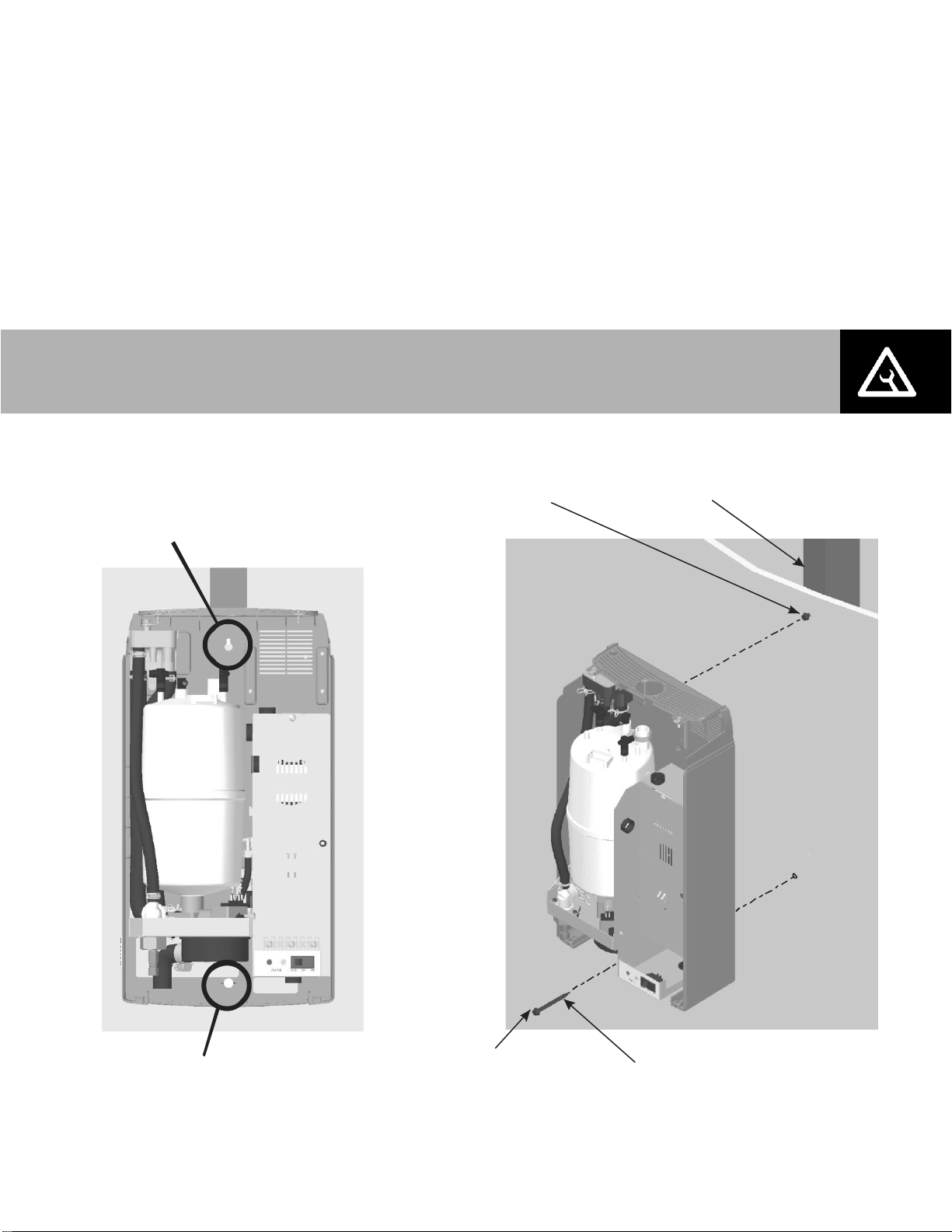
Page 45

Warning
Disconnect main power at the external disconnect before any servicing.
The inside of the humidifier cabinet contains high voltage components and wiring.
Access should be limited to authorized personnel.
Hose Clamp
Cylinder Plug
lift vertically
On/Off/Drain Switch
Cylinder
Cover Screws
Tilt cylinder
forward to clear
hose and then
lift from drain
valve.
Tilt cover
forward to .
remove.
Removing the Cylinder
1 Drain the existing cylinder by switching the On/Off/Drain switch to the Drain position. Let
the humidifier drain until no more water is flowing out to drain (usually not more than 10
minutes).
2 Turn the humidifier On/Off/Drain switch to off.
3 Close supply water shut off valve.
4 Turn off power to the humidifier with the external disconnect.
5 Remove the two screws securing the front cover.
6 Remove the cylinder plugs from the cylinder pins by pulling vertically.
7 Using a flat screwdriver loosen the hose clamp where the hose is connected to the cylinder.
8 Tip the top of the cylinder forward to pivot it out of the steam hose. When free of steam
hose lift the cylinder out.
Figure 34: Cylinder Removal
Maintenance and Servicing | 42
Page 46

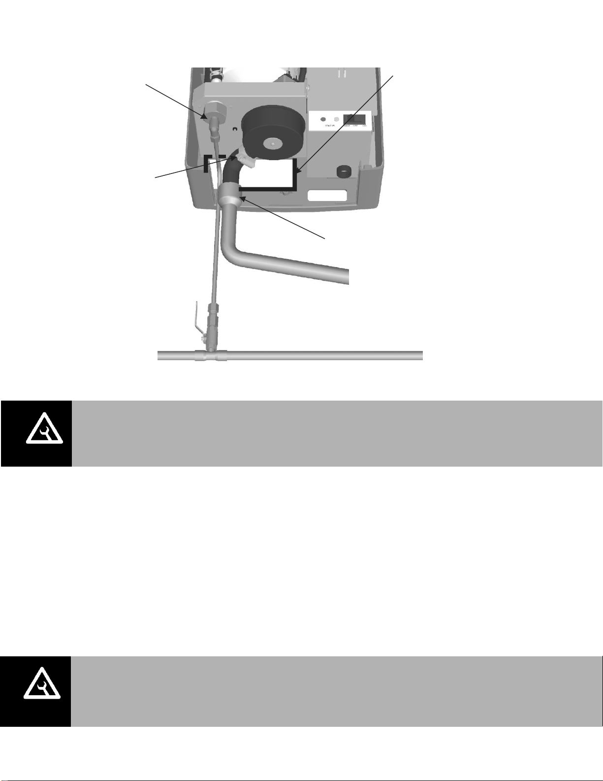
Note: Be sure to reattach the green ground wire to reduce the risk of electrical shock.
Drain Valve Cleaning
Always clean the drain valve before installing a new cylinder. Scale from the spent cylinder may
have fallen into the drain valve and could prevent its proper operation. To properly clean the
drain valve it must be removed and disassembled.
1 Disconnect spade terminals from the drain valve.
2 Remove the screw holding the green ground wire and the two screws holding the valve to
the drain pan.
3 Squeeze the tabs of the spring clamp holding the hose to the drain valve and slide it up the
hose. Pull hose from drain valve. Lift the drain valve from the drain pan.
4 Unsnap red coil cap on solenoid and remove the solenoid from the valve.
5 Loosen brass nut holding actuator to plastic housing with a wrench and disassemble
actuator.
6 Clean actuator components and valve housing (inlet port, outlet port, and cylinder port). Put
new o-ring that was supplied with new cylinder into valve.
7 Reassemble actuator making sure tapered end of spring is oriented as shown in Figure 36.
Tighten brass nut 1/4 turn past hand tight.
8 Clean out end of hose and reattach to valve. Slide hose clamp back in place and place valve
into drain pan.
9 Secure valve with 2 screws and attach green ground wire to solenoid.
Figure 35: Drain Valve
43 | Maintenance and Servicing
Page 47

Sleeve
and
Solenoid
Spring
Plunger
(Note Orientation)
CAUTION: Make sure the new cylinder is the same model as the one that was removed.
Model number is on top left corner of cylinder label.
Figure 36: Drain Valve Actuator Assembly
Installing the New Cylinder
1 Insert cylinder into drain valve. Tilt cylinder forward and fit end of steam hose to steam
outlet. Tip cylinder back into place.
2 Tighten hose clamp being careful not to over tighten and crush the plastic cylinder steam
outlet.
3 Attach color-coded cylinder plugs to the corresponding color-coded cylinder pin. Push down
completely. Connect high water sensor plug. Spring-loaded plugs should fit snuggly onto
the cylinder pin. Replace if they are loose or damaged.
4 Replace the humidifier cover and secure with two screws.
5 Turn on power to humidifier with the external disconnect.
6 Open supply water shut off valve.
7 Turn the humidifier On/Off /Drain switch to On.
Maintenance and Servicing | 44
Page 48

Note: As long as the RH2 is powered, it will automatically drain the cylinder when
there has not been a call for humidity for an extended period of time. This feature will
reduce or prevent the possibility of corrosion of the electrodes and the accumulation
of algae and bacteria growing in the cylinder. The cylinder will remain empty until
there is a call for humidity at which time the fill valve will open and refill the cylinder.
The unit will go through its normal process for optimum operation.
Extended Shutdown
Should it be required to disconnect power to the humidifier for a period of extended shut-down,
always drain the cylinder first.
1 Switch the On/Off/Drain Switch to the Drain position.
2 Wait until the humidifier is completely drained (usually takes less than 10 minutes).
3 Turn the On/Off /Drain switch to the off position.
4 Shut off power to the humidifier with the external disconnect.
5 Close the supply water shut-off valve.
Starting After Extended Shutdown
1 Check to see the humidifier has not been damaged and the installation has not been
altered. Refer to the Chapter on Start Up.
2 Turn on the power to the humidifier with the external disconnect.
3 Turn the On/Off/ Drain switch to the Drain position.
4 Wait until there is no water flowing to drain. It usually takes less than 10 minutes.
5 Follow the start up procedure in the chapter on Start Up.
45 | Maintenance and Servicing
Page 49

RH2 Maintenance Checklist
Model #: _________________
Serial #: _________________ Tag: ________
Cylinder #:
CHECK CYLINDER
Cylinder spent), yellow LED flashing 4 times in sequence.
(If Yellow LED is On and cylinder is not new then cylinder will have to be replaced soon.)
REPLACE CYLINDER
Cylinder drained.
Disconnect open, On/Off/Drain switch off, water shut off valve closed, cover removed.
Cylinder removed
Drain valve removed / cleaned / new O-Ring
Drain valve installed / ground wire attached.
New Cylinder Installed New cylinder model #
(Should be same as removed cylinder)
Cylinder plug colors match cylinder dots.
Cylinder plugs snug and in good condition.
High Water Sensor plug snug and in good condition.
Cover replaced, water shut off valve open, On/Off /Drain switch On, Disconnect Closed
SYSTEM CHECK
Yellow Led flashing? No Yes Flash Sequence?
(See Troubleshooting Chapter for actions if yellow LED is flashing)
Cylinder plugs snug and in good condition.
Electrical wiring not loose and in good condition,
Steam hoses and steam lines in good condition / No kinks in hose,
No Signs of water leaking around humidifier, steam line, condensate returns,
Inspected by: Date of inspection: _______/_______/______
Company:
Maintenance and Servicing | 46
Page 50

Troubleshooting
48 Organization of Troubleshooting Chapter
48 Troubleshooting Requirements
49 General Troubleshooting
49 Humidifier
50 Steam Distributors
50 Blower Pack
50 Digital Humidistat
51 RH2 Faults
51 LED Flash Sequence
51 Clearing a Fault
53 RH2 Wiring Diagram
54 Exploded View and Spare Parts List
58 Warranty
47 | Troubleshooting
Page 51

NOTE: Most humidifier faults are not caused by faulty equipment but rather by improper
installation. A complete fault diagnosis always involves a thorough examination of the
entire system. Often, the steam hose connection has not been properly executed, or the
fault lies with the humidity control system.
CAUTION: Be aware, when troubleshooting, that the humidifier is powered by high voltage
and familiarity with both good practices and wiring of the humidifier is recommended.
Any troubleshooting that requires opening the cabinet should be done by qualified
personnel.
Organization of Troubleshooting Chapter
The troubleshooting chapter is broken down into 2 sections.
General Troubleshooting Deals with troubleshooting incorrect humidifier operation,
steam line and plumbing issues without any control
software faults.
Humidifier Warnings and Faults Deals with faults that are generated by the humidifier
control software.
Troubleshooting Requirements
Ensure the installation meets the installation requirements outlined in the Installation
Chapter of this manual.
Familiarize yourself with the operation of the humidifier by reading the Operation Chapter of
this manual.
Wiring diagram for specific for your humidifier is installed on the inside of the humidifier
door. A generic copy of the RH2 wiring diagram is also included at the end of this chapter
for reference purposes.
When contacting your local representative or Nortec for troubleshooting assistance, please
ensure the serial number has been obtained for reference purposes.
Troubleshooting| 48
Page 52

Symptom
Cause
Corrective Action(s)
Nothing happens when On/Off
switch is turned on.
1 Fuse blown
1 Check inline fuse between transformer
and control board.
2 Incorrect Voltage
2 Check voltage against spec label and
correct.
3 Step Down Transformer not
outputting 24VAC
3 Replace the transformer
4 Incorrect primary power jumper
4 Check that jumper on high voltage
terminal block is connected between P
and terminal corresponding to supply
voltage.
Humidifier will not humidify or
not reaching RH2 setpoint
1 Safety loop open
1a Check if there is 24 VAC at terminal 2.
1b Check wiring and operation of On/Off
devices connected to terminal 1 and 2.
1c Check jumper is installed in air proving
safety loop, terminal 1 and 8.
2 No demand signal
2 Check voltage between terminal 3 and
4. For demand configuration 35% of
full-scale signal must be present for
humidifier to start.
3 Not configured correctly for
On/Off or modulating control
3 Check that J10 on control board is
removed for modulating control and
installed for On/Off control.
4 Capacity has been manually
limited
4 Check Manual Capacity adjustment
potentiometer. Clockwise increases
capacity.
5 Low conductivity water
5 Check if yellow LED is on. If operated
on low conductivity water it may take
several hours for the RH2 to reach full
output capacity. This is normal. During
this time the humidifier will not perform
any drains and the conductivity of the
water in the cylinder will increase.
6 Incorrect configuration
(Modulating or On/OFF)
6 Check J10 on control board, remove if a
modulating humidistat is being used.
7 No airflow in duct
7 Check that humidifier fan enable
(terminals 19-20) are properly wired to
furnace. Check air proving wired to
terminal 8.
Humidifier has faulted and
yellow LED is flashing
1 Software has detected an
abnormal condition
1 Refer to Table 8: Troubleshooting RH2
Faults.
General Troubleshooting
The following section provides general guidelines for troubleshooting the RH2 humidifier and
auxiliary components. For detailed troubleshooting information refer to the manuals that were
provided with the auxiliary equipment and to Table 8: Troubleshooting RH2 Faults after in this
chapter.
Table 7: General Troubleshooting
49 | Troubleshooting
Page 53

Symptom
Cause
Corrective Action(s)
Distributor spitting out water
1 Distributor not level
1 Use support at end of distributor to
ensure it is level.
2 “P” Trap too close to distributor
2 “P” Trap must be a minimum of 12 in
(30 cm) below the distributor to
ensure flow. Relocate if required.
3 Condensate line not sloped
sufficiently
3 Sufficient slope to ensure flow is
required. Reinstall if required.
4 Trap blocked
4 Check that water flows through trap.
Clear out if blocked.
5 Steam line not insulated
5 If steam line is long, condensate build
up could overload distributor
condensate port. Insulate line to
improve efficiency and install
additional condensate traps as
required.
6 Incorrect steam line installation
6 Check that steam line has been
installed with condensate traps and
slope per installation instructions on
page 12.
Condensation in duct
1 Installation clearances not
observed
1 Refer to distributor installation manual
for required clearances. Relocate
distributor if required.
2 Design conditions changed
2 Check supply air temperature and
humidity to determine if conditions
have changed.
3 High limit not functioning
3 Check setting and operation of high
limit. Replace if defective.
Symptom
Cause
Corrective Action(s)
Blower not operating
1 No power to blower pack
1a Check power connection to blower
pack.
1b Ensure unit is humidifying. The
blower will not operate if the
humidifier is not generating steam.
Symptom
Cause
Corrective Action(s)
Humidistat Reading incorrectly
1 Sensor out of calibration
1 Check reading against known reliable
instrument. If out of calibration it can
be field calibrated ±10%. Refer to
humidistat documentation for
calibration instructions.
Steam Distributors
Blower Pack
Digital Humidistat
Troubleshooting| 50
Page 54

Yellow LED
System Detected
Cause
Corrective Action(s)
1 flash
Excess Current
Current has exceeded
130% of max
1 Drain blocked water over
concentrated
1 Clean the drain line
2 Drain solenoid not energized,
water over concentrated
2 Check and correct wiring to
drain valve.
3 Filling too fast, fill valve
damaged and leaking
3 Replace the fill valve
4 Filling too fast, wrong fill valve
4 Check for correct fill valve in
parts list, replace if incorrect
5 Water supply too conductive
5a Contact Nortec
representative for
recommendation on alternate
cylinder
5b Change the water supply
6 Humidifier short cycling
6a Check if high limit or other
On/Off control is cycling
On/Off in less than 5
minutes. Check location and
setting of high limit.
6b Reduce the output by
turning down the capacity
potentiometer.
7 Wrong cylinder installed
7 Install correct cylinder model
8 Cylinder Spent but not
detected by software
8 Replace the cylinder (see
maintenance chapter)
9 Condensate from other
source
9 Remove condensate returns
other than from steam line.
10 Back pressure
10 Eliminate back pressure
RH2 Faults
The self-diagnostic system built into the RH2 is continually monitoring the operation of the
humidifier. When an abnormal condition occurs that cannot be self-corrected by the software
the RH2 will turn off power to the cylinder, drain the cylinder, and annunciate the fault using the
yellow status LED.
LED Flash Sequence
To differentiate between different fault conditions the yellow LED is flashed in different
sequences. Table 8 lists the fault sequences that can be displayed, their meaning, possible
cause and suggested corrective actions.
Clearing a Fault
Check the flash sequence against the list of fault messages and take any necessary actions
to correct the cause(s) as outlined in Table 8: Troubleshooting RH2 Faults.
Power cycle the humidifier with the On/Off switch waiting 10 seconds between turning it off
and on. If an externally powered 0-10V controller is used, it must be turned off prior to
clearing the fault.
Table 8: Troubleshooting RH2 Faults
51 | Troubleshooting
Page 55

Yellow LED
System Detected
Cause
Corrective Action(s)
2 flashes
No Current
Fill valve activated for
long time but high water
level not reached.
Fill should be faster than
1” per minute.
1 Drain valve leaking or stuck
open
1 Clean drain valve or replace
(see maintenance chapter)
2 Water shut off valve closed
2 Open shut off valve
3 Fill Valve strainer blocked
3 Clean out strainer on fill valve
inlet.
4 High system back pressure
4a Check for kinked hose
4b Check for proper
condensate removal (see
installation chapter)
4c Install fill cup extension
5 High water sensor not
connected
5 Check that cylinder plug with
white marker is connected to
short electrode with a plastic
well around it and to control
board.
6 Low water conductivity
6a Check if potable water
supplied to unit, not treated
water (RO or DI) .
6b Check conductivity of water.
If less than 150 µS/cm.
6c Add 1/4 teaspoon of salt to
fill cup and restart unit.
3 flashes
No Current, High Water
Water level at top of
cylinder with no current
1 Primary wire not looped
through current transformer.
1 Open disconnect, rewire
primary wire through current
transformer.
2 High water sensor plug is on
an electrode pin.
2 Install high water senor plug
on cylinder pin with shroud
around it.
3 Cylinder plugs installed
incorrectly
3 Check that cylinder plugs
colors match markers next to
electrodes on cylinder and
that white marked cylinder
plug is connected to short
electrode located in plastic
well.
4 flashes
Cylinder Spent
Electrodes covered with
scale.
1 Cylinder electrodes are
covered with scale and
humidifier cannot meet
demand
1 Replace cylinder with same
model number (see
maintenance chapter).
In order to clear “spent
cylinder” fault codes,
externally powered
modulating controllers will
have to be turned off before
power cycling the unit.
Table 8: Troubleshooting RH2 Faults (Continued)
Troubleshooting| 52
Page 56

RH2 Wiring Diagram
53 | Troubleshooting
Page 57

Nortec Part No.
Description
2560953
RH2+ Duct, 10lbs/hr, 120/208/240V 1P
2560952
RH2+ Space, 8lbs/hr, 120/208/240V 1P
tNortec Part No.
Description
2548759
RH Duct, 10lbs/hr, 120/208/240V 1P
2548758
RH Space, 8lbs/hr, 120/208/240V 1P
2548005
RH2 Duct, 10lbs/hr, 120/208/240V 1P
2548004
RH2 Space, 8lbs/hr, 120/208/240V 1P
Exploded View and Spare Parts List
RH2+ Spare Parts
The Nortec residential humidifier model should be confirmed.
The following spares parts are for RH2+ models only:
Spare parts RH and RH2 models can be found in RH2 manual 2549509.
Go to www.humidity.com to download RH2 manual 2549509.
Spare Parts| 54
Page 58

tNortec Part No.
Description
2560953
RH2+ Duct, 10lbs/hr, 120/208/240V 1P
2560952
RH2+ Space, 8lbs/hr, 120/208/240V 1P
RH2+ Spare Parts
The following spares parts are for RH2+ models only:
55 | Spare Parts
Figure 37: RH2 Spare parts
Page 59

tNortec Part No.
Description
2560953
RH2+ Duct, 10lbs/hr, 120/208/240V 1P
2560952
RH2+ Space, 8lbs/hr, 120/208/240V 1P
Item
Nortec Part No.
Description
1
Reference
RH2 DUCT Back Cover
or
RH2 SPACE Back Cover
2
2560780
or
2547403
RH2 DUCT Front Cover
or
RH2 SPACE Front Cover
3
2549654
RH2 Space Preformed Hose
4
1323020
Ground Clamp
5
2548008
RH2 SPACE Power Supply
6
2548314
RH2 SPACE Fan
7
2548683
RH2 SPACE Distributor
8
2573515
Fill Valve
9
2568368
RH2 SPACE Condensate Hose
10
1456000
Drain Valve Assembly
11
2548313
Optional Bottom Cover
12
2562415
Transformer Multi-tap 120/208/240V
13
2547964
Cylinder Plug Kit
14
1639011
Elbow/Compression Fitting Assembly
15
2568048
or
2568047
PCB RH2+ DUCT10 lbs/hr
or
PCB RH2+ SPACE 8 lbs/hr
16
Reference
Electrical Backplate
17
Reference
Drain Pan
18
2547998
Preformed Drain Hose
19
1583008
LED Lens
20
1323097
Rocker Switch
21
1519002
Cylinder 202
22
2569903
Fill Cup Assembly
Not Shown
1583126
1.50A Fuse
RH2+ Spare Parts
The following spares parts are for RH2 models only:
Table 9: RH2 Spare Parts List
Spare Parts| 56
Page 60

57 | Spare Parts
Page 61

Warranty
Nortec Humidity Inc. and/or Nortec Humidity Ltd. (hereinafter collectively referred to as THE
COMPANY), warrant for a period of two years after installation or 30 months from
manufacturer’s ship date, whichever date is earlier, that THE COMPANY’s manufactured and
assembled products, not otherwise expressly warranted (with the exception of the cylinder), are
free from defects in material and workmanship. No warranty is made against corrosion,
deterioration, or suitability of substituted materials used as a result of compliance with
government regulations.
THE COMPANY’s obligations and liabilities under this warranty are limited to furnishing
replacement parts to the customer, F.O.B. THE COMPANY’s factory, providing the defective
part(s) is returned freight prepaid by the customer. Parts used for repairs are warranted for the
balance of the term of the warranty on the original humidifier or 90 days, whichever is longer.
The warranties set forth herein are in lieu of all other warranties expressed or implied by law. No
liability whatsoever shall be attached to THE COMPANY until said products have been paid for in
full and then said liability shall be limited to the original purchase price for the product. Any
further warranty must be in writing, signed by an officer of THE COMPANY.
THE COMPANY’s limited warranty on accessories, not of the companies manufacture, such as
controls, humidistats, pumps, etc. is limited to the warranty of the original equipment
manufacturer from date of original shipment of humidifier.
THE COMPANY makes no warranty and assumes no liability unless the equipment is installed in
strict accordance with a copy of the catalog and installation manual in effect at the date of
purchase and by a contractor approved by THE COMPANY to install such equipment.
THE COMPANY makes no warranty and assumes no liability whatsoever for consequential
damage or damage resulting directly from misapplication, incorrect sizing or lack of proper
maintenance of the equipment.
THE COMPANY makes no warranty and assumes no liability whatsoever for damage resulting
from freezing of the humidifier, supply lines, drain lines, or steam distribution systems.
THE COMPANY retains the right to change the design, specification and performance criteria of
its products without notice or obligation.
Warranty | 58
Page 62

U.S.A.
1860 Renaissance Blvd
Sturtevant, WI 53177
826 Proctor Avenue
Ogdensburg, NY 13669
CANADA
2740 Fenton Road
Ottawa, Ontario K1T 3T7
TEL: 1.866.NORTEC1
EMAIL: nortec@humidity.com
WEBSITE: www.humidity.com
 Loading...