

Page 1

Important: Read and save these instructions. This guide to be left with equipment.
1509311-B | 20 FEB 2010
OnLine
GSTC/SETC
Installation and
Operation Manual
Includes installation, operation
maintenance and troubleshooting
information for your GSTC/SETC
Nortec OnLine Options.
Page 2

INSTALLATION DATE (MM/DD/YYYY)
MODEL #
SERIAL #
Thank you for choosing NORTEC.
Proprietary Notice
This document and the information disclosed herein are proprietary data of WALTER MEIER LTD. Neither this
document nor the information contained herein shall be reproduced used, or disclosed to others without the
written authorization of WALTER MEIER LTD., except to the extent required for installation or maintenance of
recipient’s equipment. All references to the NORTEC name should be taken as referring to WALTER MEIER LTD.
Liability Notice
NORTEC does not accept any liability for installations of humidity equipment installed by unqualified personnel
or the use of parts/components/equipment that are not authorized or approved by NORTEC.
Copyright Notice
Copyright 2009, WALTER MEIER LTD. All rights reserved.
Page 3

Contents
1 Overview
1 Offerings
1 Humidifier Wiring
4 Ethernet Connections
4 GPRS or Dial-up Connection
4 User Webpage Interface
10 Configuration Screen
14 Nortec OnLine Start-Up Checklist
15 Troubleshooting
15 Gateway Indicator Lights
16 Spare Parts
17 Nortec OnLine Configuration Form
Page 4

Page 5

Overview
The NORTEC OnLine Option provides a web-based remote monitoring capability to equipped
GSTC or SETC series humidifiers. The NORTEC OnLine option operates in conjunction with a
centralized server based at NORTEC's facilities. This server allows the user to monitor and
control various aspects of the humidifier operation. If a fault or service warning is detected the
NORTEC server will send an email response to three user-specified personnel. NORTEC OnLine
also provides NORTEC with the ability to diagnose the humidifier's performance remotely,
ensuring quick response to customer inquiries.
NORTEC OnLine provides the advantages of immediate notification and quick diagnosis of
humidifier fault conditions, should they arise. NORTEC OnLine also provides a user-friendly BMSlike interface, even when a dedicated Building Management System is not available or
unfeasible. All that is required for NORTEC OnLine’s operation is either an internet connection,
an external phone line or a wireless network connection.
Offerings
NORTEC OnLine supports three types of connections to the internet: Ethernet, Dialup modem,
and GPRS modem. Both static IP and DHCP addressing is available for ethernet connections.
Simply specify at the time of order, which type of connection type would be preferable and any
details that may apply (refer to the configuration form at the back of the manual). Once in the
field, a user can differentiate between the different connection types by inspecting a tag present
on the OnLine module. This identifier tag will provide details such as connection type and part
number information.
For sites where LAN/internet connections are available, the OnLine module may be plugged into
the network through an ethernet port present on the control board. NORTEC OnLine is capable
of operating with either a Static IP address or a Dynamic IP address. Wide area network (WAN)
port 5222 must be opened to TCP traffic for the units to communicate with the NORTEC OnLine
Service.
The NORTEC OnLine module also comes equipped with a serial port which allows a dial-up
modem or a wireless GPRS modem to be connected. All the necessary programming for the
connection details will be pre-programmed at the factory.
Humidifier Wiring
It is possible to network up to a maximum of 8 units to a single NORTEC OnLine module. This
OnLine module is located internally to the GSTC or SETC unit. When multiple humidifiers are
present, only a single module is required and will be installed inside a 'lead' unit, which can be
specified by the user. Since each unit is separately addressed, it is possible to monitor and
control each unit independently.
Installation | 1
Page 6
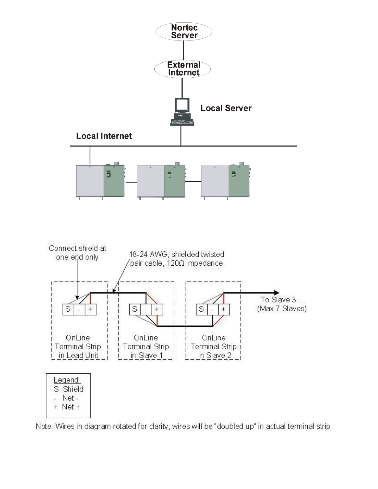
Figure 1: Networking Layout
Figure 2: Networking for 2009 Models and Newer
2 | Installation
Page 7
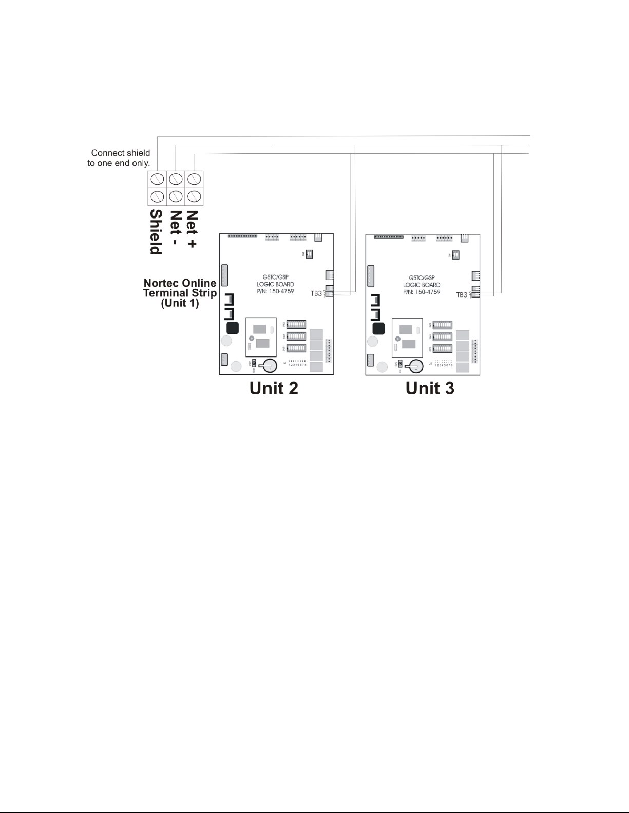
The necessary internal wiring for the gateway is already present except for the network
Figure 3: Connecting Multiple Humidifiers to a Lead Humidifier –
2008 Models and Older
connection that can be made internally to the unit. To network multiple units to a single
Gateway, the units may be daisy-chained to each other using the network link terminals at the
TB3 connection jack on the humidifier logic board, see Figure 3.
Table 1 refers to the recommended wire types and maximum recommended lengths from the
NORTEC OnLine module in the lead unit. Since communication between the humidifiers and
NORTEC OnLine will always occur via a EIA-485 signal type, NORTEC recommends using 18-24
AWG shielded (120 Ω impedance), twisted pair wire between the lead humidifier and each of
the secondary humidifiers. Cable runs between the NORTEC OnLine module and the furthest
“slave” humidifier should not exceed 2,600 feet. Signal boosters or repeaters may be necessary
for longer wire runs. The shield wire(s) should be connected at one end only.
The NORTEC OnLine module has been designed and tested to operate with a variety of thirdparty manufacturers equipment that promote wireless connectivity. Should a user desire to
connect the OnLine module to the internet via a wireless connection such as 802.11b or g class
network, NORTEC can provide recommendations on which equipment to use.
Installation | 3
Page 8

Ethernet Connections
Signal Type
Polarity
Recommended Cable
Maximum Recommended
Distance from NORTEC Module
A
B
EIA-485, 2-wire
Net +
Net -
18-24 AWG Shielded, Twisted Pair
120 Ω impedance
2,600 ft
To connect NORTEC OnLine to the internet via a local area network, insert the ethernet cable
into the port on the NORTEC OnLine module inside the lead humidifier. The serial port is not
used in this configuration. The option for Static IP or DHCP addressing is specified at time of
order, the units should be visible on the network after being connected. In order to connuicate
with the NORTEC OnLine service Lan Port 5222 must be opened (”forwarded or triggered”) for
TCP traffic.
GPRS or Dial-up Connections
The NORTEC OnLine module is also able to connect with the NORTEC Server via a dial-up
connection to a local Internet Service Provider or even through a GPRS connection. Should such
a connection be desirable NORTEC can recommend a variety of third party manufacturers
equipment that the NORTEC OnLine module has been proven to work well with.
If a dial-up or GPRS connection is desired it will be necessary to contact NORTEC at the time of
order to provide information on the required settings.
These modems are connected to the serial port on the OnLine module. The ethernet port is not
used in this case.
Table 1: Recommended Wire Types and Lengths
User Webpage Interface
The NORTEC OnLine web page can be accessed via the internet address www.norteconline.com.
After initially logging into the NORTEC OnLine server the user will be presented with a list of
humidifiers currently registered with the Server program. Each serial number and an address
descriptor.
By clicking on the humidifier name, the user will then be brought to a status screen with an
image of the selected humidifier. Refer to Figure #5.
The status screen, refer to Figure 6 provides the user with a quick reference to the unit’s
operation.
Several key status values can be gathered at a glance. Refer to Table 2 for a description of the
variables displayed on the status screen.
4 | Installation
Page 9

Figure 4: NORTEC OnLine Homepage
Figure 5: List of Humidifiers
Installation | 5
Page 10

Figure 6: Status Screen
6 | Installation
Page 11

Table 2: Status Screen Variables
Variable Name
Displayed Information
Description
Product Line
GSTC
SETC
3 Day Drain
On/Off Chart Item
Indicates if the three day tank drain feature is
enabled. 0=disabled, 1=enabled.
X
X
Burner 1 Status
On/Off Animated
Indicates if Burner 1 is on.
X
Burner 2 Status
On/Off Lamp Indicator
Indicates if Burner 2 is on (if equipped)
X
Burner 3 Status
On/Off Lamp Indicator
Indicates if Burner 3 is on (if equipped)
X
Burner 4 Status
On/Off Lamp Indicator
Indicates if Burner 4 is on (if equipped)
X
Burner 5 Status
On/Off Lamp Indicator
Indicates if Burner 5 is on (if equipped)
X
Burner 6 Status
On/Off Lamp Indicator
Indicates if Burner 6 is on (if equipped)
X
Steam Exchanger
Status
On/Off Animated
Indicates if steam is flowing through the heat
exchanger.
X
Capacity Limit
0-100% Chart Item
Indicates the current value for the capacity limit
set point (adjustment) on the humidifier.
X
X
Channel 1
Demand%RH
0-100% Chart Item
Indicates the current Demand or %RH signal
being supplied to Channel 1 of the humidifier
from a connected sensor.
X
X
Channel 1 Setpoint
0-100% Chart Item
Shows current value for the setpoint of channel
1. This value is only applicable when unit is set
to respond to a %RH signal.
X
X
Channel 2
Demand/%RH
0-100% Chart Item
Indicates the current Demand or %RH signal
supplied to Channel 2 of the humidifier from a
connected sensor.
X
X
Channel 2 Setpoint
0-100% Chart Item
Shows current value for the setpoint of channel
2. This value is only applicable when unit is set
to respond to a %RH signal and configured for
dual channel.
X
X
Drain Valve Status
On/Off Animated
Indicates when the tank drain has been
activated and the unit is draining water.
X
X
Fault Indicator
On/Off Lamp
Indicator
Provides current fault status. The red fault light
is lit when a fault is detected.
X
X
Fill Valve Status
On/Off Animated
Indicates if the humidifier is filling the water
tank.
X
X
Full Tank Blowdown
On/Off Chart Item
Indicates if the full tank blowdown feature is
enabled or disabled. Feature is toggled by dip-
switch on mainboard.
X
X
Keep WarmKeep
Warn used on
status screen not
Keep Warm.
On/Off Chart Item
Indicates if the water tank keepwarm feature is
enabled or disabled. Feature is toggled by dip-
switch on mainboard.
X
X
Operational Hours
Hours Chart Item
Displays the amount of the time the humidifier
has been in operation.
X
X
Remaining Service
Hours. Hours to
next Service.
Hours Chart Item
Displays the number of operational hours left
until the next suggested service period is due.
X
X
Serial Number
Alpha-Numeric String
Indicates the Humidifiers Serial Number for
quick reference.
X
X
Installation | 7
Page 12

Table 2: Status Screen Variables - CONTINUED
Variable Name
Displayed Information
Description
Product LIne
GSTC
SETC
Service Indicator
On/Off Lamp
Indicator
Provides current service status. The yellow
service light is lit when service is due.
X
X
Software Version
Numerical Chart Item
Indicates the software version installed on the
Humidifiers mainboard.
X
X
Steam Production
On/Off Animated
Indicates that the humidifier is producing steam
in response to a demand signal.
X
X
System Demand
Correct Output
0-100% Numerical Data
Displays the humidifier's current demand
output
X
X
Unit Address
Mailing Address Chart
Item
Provides details on the Humidifier's location.
X
X
Unit Model
Unit Identifier Chart Item
Indicates the model type & size of the selected
humidifier.
X
X
Unit Status
On/Off Lamp
Indicator
Indicates if unit has responded to a demand
signal. The green LED is on when a demand
signal is present.
X
X
Water Level High
On/Off Lamp
Indicator
Yellow light is on if water is at a high level. Light
combinations are possible for mid-state water
levels.
X
X
Water Level MidRange
On/Off Lamp Indicator
Green light is on if water is at optimal level.
Light combinations are possible for mid-state
water levels
X
X
Water Level Low
On/Off Lamp Indicator
Red light is on if water is at a low level. Light
combinations are possible for mid-state water
levels.
X
X
Weighted Hours
Hours Chart Item
Equivalent operating hours convoluted to 100%
steam production. Ex. Weighted hours = 2
hours at 50% demand.
X
X
Manual Drain
On/Off Chart Item
Drain unit when “on”.
X
X
Pre-Clean
On/Off Chart Item
Initiates a pre-clean cycle.
X
X
Power Reset
On/Off Chart Item
Performs a software reset similar to turning the
unit off and then on again.
0: Standalone unit (default setting)
1: Unit is Master
X
X
Multimode
Status Item
2: Unit is Slave
Lists current signal type the unit is configured
for
0: 0-5Vdc
1: 1-5Vdc
2: 0-10Vdc
3: 2-10Vdc
4: 0-16Vdc
5: 3.2-16Vdc
6: 0-10mA
X
X
8 | Installation
Page 13

Table 2: Status Screen Variables - CONTINUED
Variable Name
Displayed
Information
Description
Product Line
GSTC
SETC
Limit Type
Status Item
7: 4-20mA
X
X
3 Day Drain Delay
Time Status Item
Displays idle time remaining before tank drains.
Lists current signal type the unit is configured for
0: 0-5Vdc
1: 1-5Vdc
2: 0-10Vdc
3: 2-10Vdc
4: 0-16Vdc
5: 3.2-16Vdc
6: 0-10mA
X
X
Limit Signal Type
Status Item
7: 4-20mA
X
X
Time Proportioning
Active
On/Off Chart Item
Displays that unit has received demand such that
time proportioning has activated.
X
X
Float Check Active
On/Off Chart Item
Active when unit is currently performing a 23 hour
float check.
X
X
Installation | 9
Page 14

Configuration Screen
Figure 7: Configuration Button
Figure 8: Configuration Screen
By selecting the configuration button, see Figure 7 & Figure 8, located near the top of the
webpage, the user is able to adjust control parameters for the humidifier.
Table 3 provides a description of the control variables provided to the user.
10 | Installation
Page 15

Table 3: Screen Status Variable
Variable Name
Setting Range
Description
Product Line
GSTC
SETC
Capacity Limit
0-100%
Allows the user to adjust the total steam
output the unit will be able to produce at
100% demand.
X
X
Channel 1 Setpoint
10-95%
Sets the Channel 1 Setpoint. This feature
is only enabled when the humidifier is set
to operate with an RH signal.
X
X
Channel 2 Setpoint
10-95%
Sets the Channel 2 Setpoint. This feature
is only enabled when the humidifier is set
to operate with an RH signal.
X
X
Disable Humidifier
Enabled/Disabled
Forces the humidifier into a lockout state
where steam production is halted and the
unit will not respond to any demand input.
X
X
Installation | 11
Page 16

At the top of the screen the user is presented with options for three different screens, see
Figure 9: Three Screen Options
Figure 10: Trend Data
Figure 9. One option will provide a trending graph, see Figure 10, that monitors points such as
%RH/Demand and setpoint settings for channel 1 and channel 2 as well as the current
humidifier’s output. This trend graph is capable of keeping historical data for each particular
unit.
12 | Installation
Page 17

Figure 11: Fault and Service History Table, provides a list of up to 18 fault or service errors that
Figure 11. Fault and Service History Table
Figure 12. Parameter Table
the humidifier has experienced . This can provide valuable troubleshooting information when
faced with a recurring problem.
Figure 12: Parameter Table, provides an in-depth view of all the variables available through
NORTEC OnLine. From the parameter listings a user can determine if a certain gas burner has
been disabled, the proportional coefficient for the PI band on channel 1, or even what version of
the GSTC software the unit is currently operating with.
Installation | 13
Page 18

Nortec OnLine Start-Up Checklist
Humidifier-to-humidifier connection:
Each individual humidifier linked to lead unit.
Connection can be direct or daisy-chained to other units.
Shield connected to lead unit only (wire should not be connected at other end).
Lead unit wired to local network (Ethernet, GPRS, Dial-up).
Network activity verified.
Port 5222 open to TCP traffic.
Ensure power is being supplied to the humidifier and NORTEC OnLine module.
Verify power to OnLine module (Power LED should be lit).
After power-up, verify network communication.
Verify variable operation after mapping is complete.
Perform regular humidifier start-up check.
Wiring
Network Connection
Start-Up Procedure
14 | Installation
Page 19

Troubleshooting
LED Name
Color
Function
Module Status
Off
Indicates that the OnLine module is not receiving power.
Green
Indicates the OnLine is operating normally.
Orange
Indicates that the OnLine is loading the firmware installed on the
module.
Serial Link Status
Flashing Green
Indicates that the OnLine is receiving a network packet from an
serial connection.
Flashing Red
Indicates that the OnLine is transmitting a network packet on a
serial connection.
Orange
Displayed when the OnLine is booting.
Ethernet Activity /
Collision
Flashing Green
Indicates that the OnLine is receiving a network packet from an
Ethernet connection.
Flashing Red
Indicates that the OnLine is transmitting a network packet on a
Ethernet connection.
Network Link
Off
No network connection is present.
Green
The OnLine has detected the presence of a 10Mbps network.
Orange
The OnLine has detected the presence of a 100Mbps network.
Gateway Indicator Lights
The OnLine module has four status indicator LEDs that provide a quick-reference for
troubleshooting communication faults with the Nortec OnLine option. Table 4 provides a
description of each LEDs function.
Table 5 details common problems and solutions.
Table 4: OnLIne Module Status LED Description
Troubleshooting | 15
Page 20

Table 5: Troubleshooting Communication Problems
Problem
Solution
The NORTEC server
cannot read/write
any information to
any of the networked
humidifiers.
Verify that the network connection is made and is connected properly.
Verify that firewall port 5222 is open to TCP traffic.
Verify that the correct network settings are being used. The OnLine module may need
to be restarted to load the new settings.
Check the ethernet link (if ethernet enabled) or serial link (if modem enabled)
communication LED's to determine if there is any network traffic being sent or
received by the OnLine module from the NORTEC server. Verify proper connections to
networked humidifiers.
Turn the OnLine module off for several seconds then switch it back on to reload the
control program. Allow for some time for the network variables to be polled.
The NORTEC server
network can see
some of the
networked
humidifiers but not
others.
Ensure proper connections to the humidifiers.
Disconnect all of the humidifiers from the NORTEC OnLine module except for the unit
that is not responding to the network. Disconnect power to the OnLine module, wait a
moment, then reconnect power. Check Serial Link LED transmit/receive lights to see
if the module can talk to the humidifier.
Verify that each unit has a unique modbus address (no conflicts).
Part Number
Item
Description
1509602
NORTEC Online Module - Dial-up
Configuration.
Spare part for On-Line module with dial-up
settings.
1509603
NORTEC Online Module - GPRS Configuration.
Spare part for On-Line module with dial-up
settings.
1509604
NORTEC Online Module - Static IP
Configuration.
Spare part for On-Line module with wired
ethernet and static IP settings.
1509605
NORTEC Online Module - DHCP Configuration.
Spare part for On-Line module with wired
ethernet and dynamic IP settings.
1509349
Communication Cable for OnLine module.
Cable with RS-12 plug for On-Line module.
Spare Parts
Table 6: Spare Parts
16 | Troubleshooting
Page 21

Troubleshooting | 17
Page 22

Page 23

Warranty
Walter Meier Inc. and/or Walter Meier Ltd. (hereinafter collectively referred to as THE
COMPANY), warrant for a period of two years after installation or 30 months from
manufacturer’s ship date, whichever date is earlier, that THE COMPANY’s manufactured and
assembled products, not otherwise expressly warranted (with the exception of the cylinder), are
free from defects in material and workmanship. No warranty is made against corrosion,
deterioration, or suitability of substituted materials used as a result of compliance with
government regulations.
THE COMPANY’s obligations and liabilities under this warranty are limited to furnishing
replacement parts to the customer, F.O.B. THE COMPANY’s factory, providing the defective
part(s) is returned freight prepaid by the customer. Parts used for repairs are warranted for the
balance of the term of the warranty on the original humidifier or 90 days, whichever is longer.
The warranties set forth herein are in lieu of all other warranties expressed or implied by law. No
liability whatsoever shall be attached to THE COMPANY until said products have been paid for in
full and then said liability shall be limited to the original purchase price for the product. Any
further warranty must be in writing, signed by an officer of THE COMPANY.
THE COMPANY’s limited warranty on accessories, not of the companies manufacture, such as
controls, humidistats, pumps, etc. is limited to the warranty of the original equipment
manufacturer from date of original shipment of humidifier.
THE COMPANY makes no warranty and assumes no liability unless the equipment is installed in
strict accordance with a copy of the catalog and installation manual in effect at the date of
purchase and by a contractor approved by THE COMPANY to install such equipment.
THE COMPANY makes no warranty and assumes no liability whatsoever for consequential
damage or damage resulting directly from misapplication, incorrect sizing or lack of proper
maintenance of the equipment.
THE COMPANY makes no warranty and assumes no liability whatsoever for damage resulting
from freezing of the humidifier, supply lines, drain lines, or steam distribution systems.
THE COMPANY makes no warranty and assumes no liability whatsoever for equipment that has
failed due to ambient conditions when installed in locations having climates below 14°F (10°C) during January or above 104°F (40°C) during July.
THE COMPANY retains the right to change the design, specification and performance criteria of
its products without notice or obligation.
Page 24

Certificate No. 002419
U.S.A.
Walter Meier (Climate USA) Inc.
826 Proctor Avenue
Ogdensburg, NY 13669
CANADA
Walter Meier (Climate Canada) Ltd.
2740 Fenton Road
Ottawa, Ontario K1T 3T7
TEL: 1.866.NORTEC1
FAX: 613.822.7964
EMAIL: northamerica.climate@waltermeier.com
WEBSITE: www.humidity.com
www.norteconline.com
 Loading...