

Page 1
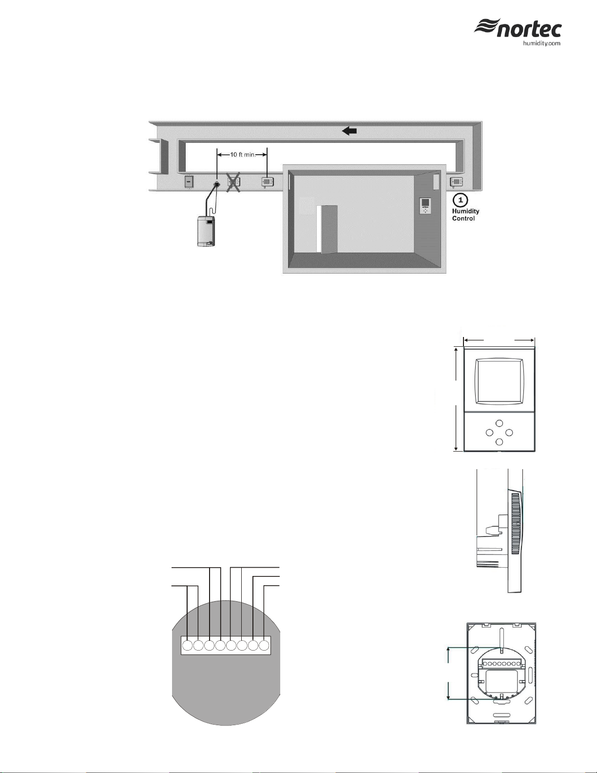
1 - Wall Humidity Control Installation
Location:
1 Do not install humidistat on an outside wall, near a heat source and/or in direct sunlight.
2 Install the humidistat on a surface that is flat and clean.
3 Install a vapor barrier to prevent sensor from interacting with inner wall draft.
4 Use a sealed, single gang electrical mounting box (recessed in the wall) to mount the humidity sensor.
Installation:
1 Pull cables 6” (15 cm) out of the wall.
2 Remove front face with digital display by loosening plastic retaining screw at the bottom. The front face
will unhinge from the top of the retaining clips.
3 Connect the control wires to the terminals according to wiring diagram 2548733 in this document. Figure
2 outlines the terminal layout.
4 Secure the metal bracket to the mounting electrical box using 2 screws (#6 x 3/4” Phillips). Make sure the
heads do not stand out more than 1/5” (5 mm) from mounting surface.
5 Remount front face on metal bracket. Ensure clips engage the grooves on top of the bracket. Gently
tighten bottom plastic retaining screw.
Configuration:
1 Using keypad, set specified humidity. For general health and comfort, a humidity setting of 50% is
recommended.
2 See Table 3 for outdoor temperature setback configuration, if optional outdoor temperature sensor is
supplied (P/N 2520263 or 2553858).
On/Off Digital Wall Humidistat Installation Instructions
1234
567
8
Humidify Relay
24 Vac
Com
Fan (Furnace) Relay
NTC Sensor
Figure 2: Terminal Strip
112 (4.4")
73 (2.9")
32 (1.2")
58 (2.3")
15
(.6")
Figure 1: Wall Humidistat Installation Locations
Figure 3: Dimensions
This document covers the operation and installation instructions for the following digital humidistat:
Part #: 2548731
Description: ON/OFF Wall Humidistat
2549736-D | 22 July 2014 Introduction | 1
Page 2
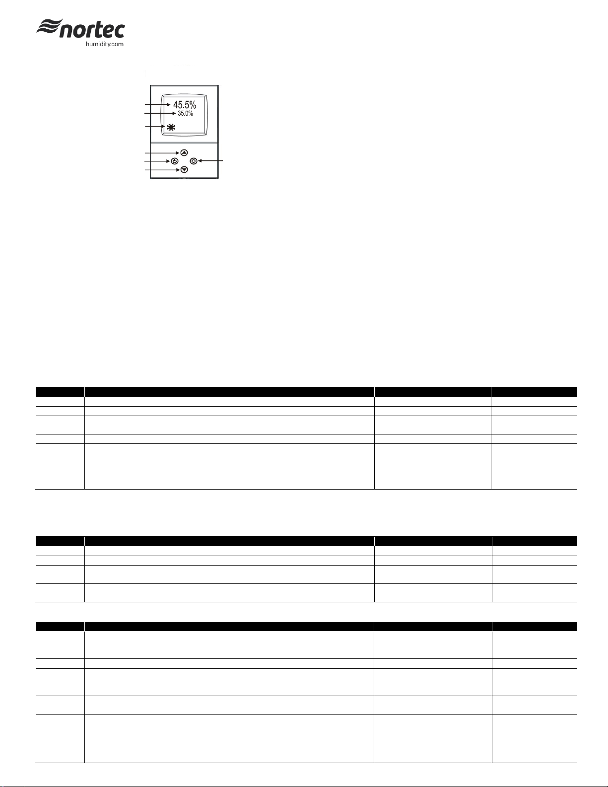
1
2
3
4
5
6
7
Legend:
1 Display of current humidity value.
2 Display of setpoint.
3 Snowflake displayed if outdoor temperature setback active.
4 Adjusts setpoint and calibration (up).
5 Power ON/OFF.
6 Toggles between RH setpoint and temperature (if temperature sensor
present).
7 Adjusts setpoint and calibration (down).
Parameter
Description
Range
Default
UP 00
Enable change of operation modes
ON, OFF
ON (Enabled)
UP 01
Enable change of setpoints
ON, OFF
ON (Enabled)
UP 02
State after power failure:
0 = Switched OFF, 1 = Switched ON, 2 = state before power failure
0, 1, 2
2
UP 03
Celsius or Fahrenheit, Select ON for Fahrenheit, OFF for Celsius
ON, OFF
OFF (Celsius)
UP 04
Select contents of small digits in standard mode:
00 = OFF
01 = Setpoint
02 = Humidity Sensor
03 = External Temperature Sensor
0…3
01 Standard:
show setpoint
Parameter
Description
Range
Default
CP 00
Minimum setpoint limit in humidification mode
0…100%
10%
CP 01
Maximum setpoint limit in humidification mode
0…100%
90%
CP 02
Start delay for fan
(Time the fan runs before control output starts)
0…255 s
10 s
CP 03
Stop delay for fan
(Time the fan keeps running after control output stops)
0…255 s
90 s
Parameter
Description
Range
Default
CP 04
Enable temperature setback
OFF = Temperature setback is disabled
ON = Temperature setback is enabled
ON, OFF
OFF
CP 05
Setpoint limit at full setback
0…100%
20%
CP 06
Lower temperature limit:
Outside temperature with maximum setback
The setpoint will be equal to the minimum setpoint limit
-40…60°C
-40…160°F
-30°C (-22°F)
CP 07
Upper temperature limit:
Outside temperature at begin of setback.
-40…60°C
40…160°F
0°C (32°F)
CP 08
Number of seconds taken into account to calculate the averaging input signal.
Low value = fast response
High value = slow response
0…100
30
Duct Humidistat LCD Display
Sensor Calibration
The humidity sensor is factory calibrated, however, it can be field recalibrated. The calibration routine can be accessed by pressing the option key for > 3
seconds. Option key = the right key on the wall mount and middle key on the right side of the duct mount. Once the display changes select CAL H, press OPTION
key again - the offset value is now shown.
Press up down keys to change. Press option key again to save changed value and return to previous level.
Login Procedure
Most applications can use default values.
User Parameters (Password 0009)
1 Press UP and DOWN button simultaneously for three seconds. The display shows the software version in the large digits and the product code in the small
digits.
2 Pressing the OPTION button will indicate CODE on the small digits and 0000 on the large digits.
3 The code for accessing the control parameters is 0009
4 Select this using UP or DOWN buttons.
5 Press OPTION button after selecting the correct code.
6 Once logged in, the parameter is displayed immediately.
7 Select the parameters with the UP/DOWN buttons. Change a parameter by pressing the OPTION button. Three triangles will show up on the lower right and
indicate that the parameter may be modified now. Use UP or DOWN buttons to adjust the value.
8 After you are done, press OPTION or POWER in order to return to the parameter selection level.
Table 1: User Parameters
Control Parameters (Password 0241)
NOTE: Only experts should change these settings! See user parameters for login procedure.
Table 2: Output Configuration
Table 3: Temperature Setback Configuration - *For humidity control only.
2 | Introduction
Page 3

Power Supply
Operating Voltage
24 V AC/DC ± 10 %, 50…60 Hz
Power Consumption
Max. 1.5 VA
Electrical Connection
Terminal Connectors,
wire: AWG 24…12
Internal rectification:
Signal ground = power ground
Half wave rectified
Isolation transformer required
Signal Inputs
Humidity Input:
Range
Accuracy
Hysteresis
Element: Polymer-Based Capacity Sensor
0…100% r.H.
10%...90% r.H. 5.0%
0…10% and 90…100% 7.0%
±1% r.H.
Temperature Input
Range
External NTC (P/N: 2520263)
-40…70°C (-40…158°F)
Accuracy
-40…0°C (-40…32°F): 0.5 C
0…50°C (32…122°F): 0.2 C
50…70°C (122…158°F): 0.5 C
Signal Outputs
Digital Switching Outputs
Switching type
AC Switching power
DO1…DO2
Relays
2 x 1.0 A, 24 Vac max.
Environment
Operation
Climatic Conditions
Temperature
Humidity
To IEC 721-3-3
class 3 K5
0…50 °C (32…122 °F)
<95 % r.H. non-condensing
Transport & Storage
Climatic Conditions
Temperature
Humidity
Mechanical Conditions
To IEC 721-3-2 and IEC 721-3-1
class 3 K3 and class 1 K3
-25…70 °C (-13…158 °F)
<95 % r.H. non-condensing
class 2M2
Standards
Product standards
Automatic electrical controls for household and
similar use
EN 60 730 –1
EN 60 730 – 2 – 9
Degree of Protection
IP30 to EN 60 529
Safety Class
III (IEC 60536)
Housing
Cover, back part
Mounting Plate
Polycarbonate PC (UL94 class V-0)
PTFE coated 1μm pores
General
Dimensions (H x W x D):
Front part:
Power case:
112 x 73 x 15 mm (4.4” x 2.9” x 0.6”)
ø 58 x 32 mm (ø 2.3” x 1.3”)
Weight (including package)
220g
Display
Cause
Symptoms
Corrective Action
Err1 Humidity sensor faulty. The humidity
sensor is damaged.
The LCD screen will report the message
Err1.
Check that the humidity
sensing element is not loose
Err2
External input for temperature setback
missing or damaged.
The LCD screen will report the message
Err2.
Check that the temperature
sensor is connected to the
humidistat. If the sensor is
connected and the error
message persists a
replacement sensor should
be ordered.
Table 4: Technical Specification
Power Failure
Upon power-interruption, all parameters and setpoints are memorized in non-volatile memory and therefore do not have to be re-entered again.
NOTE: If at any time this troubleshooting guide fails to provide the information needed Nortec’s Technical Support Department can be reached at 1-866-
NORTEC-1 to provide assistance.
2549736-D | 22 July 2014 Introduction | 3
Table 5: Error messages and Troubleshooting Guide
Page 4

4 | Introduction
 Loading...