

Page 1
NHSC / NHDI
Nortec OnLine
Installation Instructions
IMPORTANT: Read and save this guide for future
reference. This guide to be left with equipment owner.
Form #06-292 252-0819
Page 2

Table Of Contents
OVERVIEW 1
NETWORKING 1
OFFERINGS 1
WIRING 2
- ETHERNET CONNECTIONS ...............................2
- GPRS OR DIAL-UP CONNECTIONS ...........................2
VARIABLE DEFINITION 2
USER WEBPAGE INTERFACE 3
- LIST OF HUMIDIFIERS ..................................3
- STATUS SCREEN .....................................3
- CONFIGURATION SCREEN ................................6
- TREND DATA .......................................8
- FAULT & SERVICE HISTORY ...............................9
- PARAMETER LINK .....................................9
NORTEC ONLINE START-UP CHECKLIST ..........................10
TROUBLESHOOTING: .....................................10
NORTEC ONLINE MODULE STATUS LED DESCRIPTION..................11
TROUBLESHOOTING COMMUNICATION PROBLEMS ...................11
SPARE PARTS .........................................12
Page 3
OVERVIEW
The Nortec OnLine Option provides a
TCP/IP-based remote monitoring capability to
equipped NHSC or NHDI series humidifiers. The
Nortec OnLine option operates in conjunction with a
centralized server based at Nortec's facilities. This
server allows the user to monitor and control various
aspects of the humidifier operation. If a fault or service
warning is detected the Nortec server will send an
email response to three user-specified personnel.
Nortec OnLine also provides Nortec with the ability to
diagnose the humidifier's performance remotely,
ensuring quick response to customer inquiries.
Nortec OnLine provides the advantages of
immediate notification and quick diagnosis of
humidifier fault conditions, should they arise. Nortec
OnLine also provides a BMS-like interface when a
dedicated Building Management System is not
available or unfeasible. All that is required for Nortec
OnLine’s operation is either a Ethernet connection, an
external phone line or a wireless network connection.
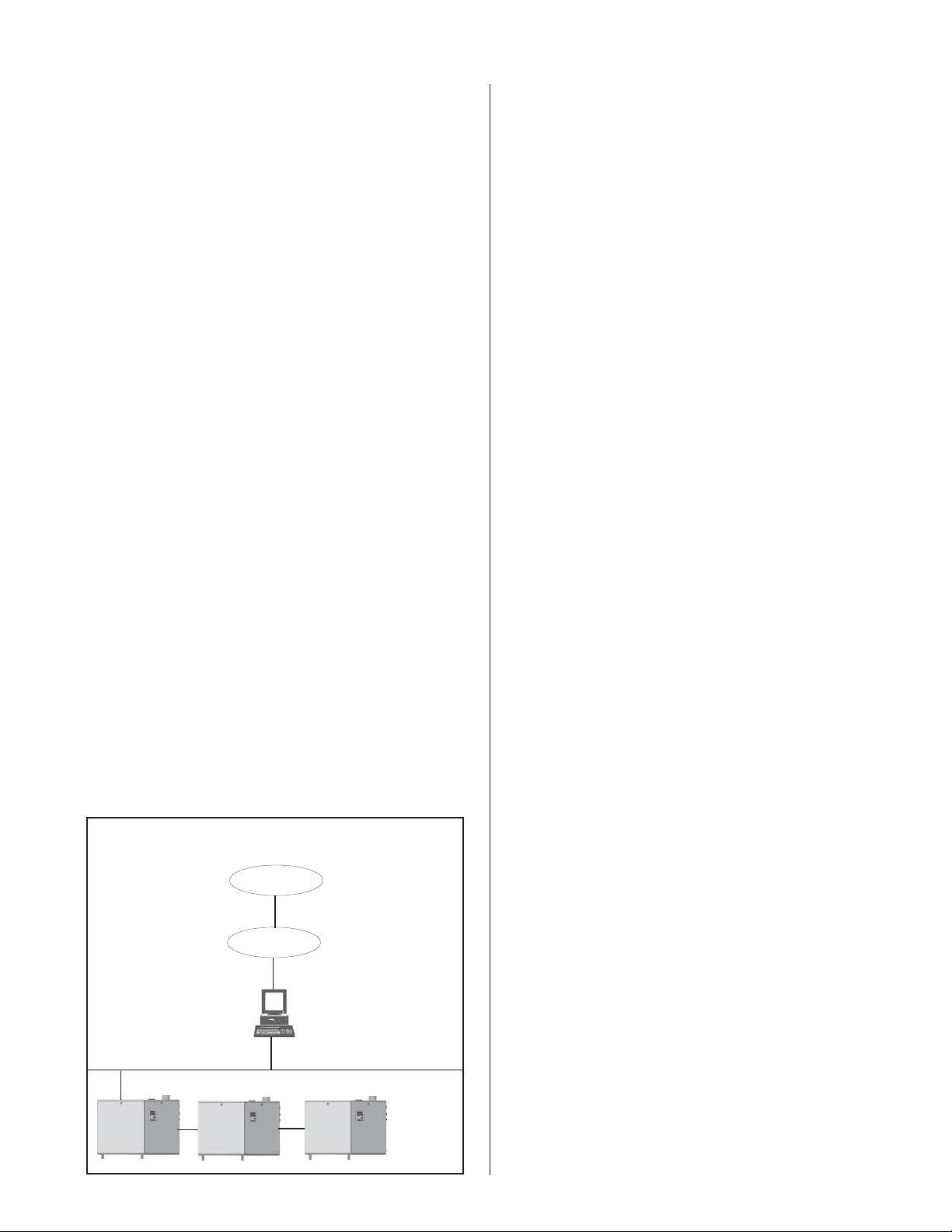
NETWORKING
It is possible to network up to a maximum of 8
humidifiers, configured for Nortec OnLine, to a single
Nortec OnLine Module. This OnLine Module is located
internally to the humidifier. When multiple humidifiers
are desired, only a single module is required and will
be installed inside a 'lead' unit, which can be specified
by the user. Since each unit is separately addressed, it
is possible to monitor and control each unit
independently.
OFFERINGS
Different networking configurations may be
achieved and are mostly dependant on the type of
network present at the site. Nortec OnLine has been
designed to be used over a variety of network
topographies. Simply specify at the time of order,
which type of connection type would be preferable and
any details that may apply (refer to the configuration
form at the back of the manual). Once in the field, a
user can differentiate between the different connection
types by inspecting a tag adjacent to the OnLine
Module. This identifier tag will provide details such as
connection type and part number information.
For sites where Network Ethernet connections are
readily available, the OnLine Module may be plugged
into the Internet through an Ethernet port present on
the control board. Nortec OnLine is capable of
operating with either a Static IP address or a Dynamic
IP address.
The Nortec OnLine Module also comes equipped
with a serial port which allows a dial-up modem or a
wireless GPRS modem to be connected. All the
necessary programming for the connection details will
be pre-programmed at the factory.
Local Internet
Figure #1
Networking
Nortec
Server
External
Internet
Local Server
-1-
Page 4
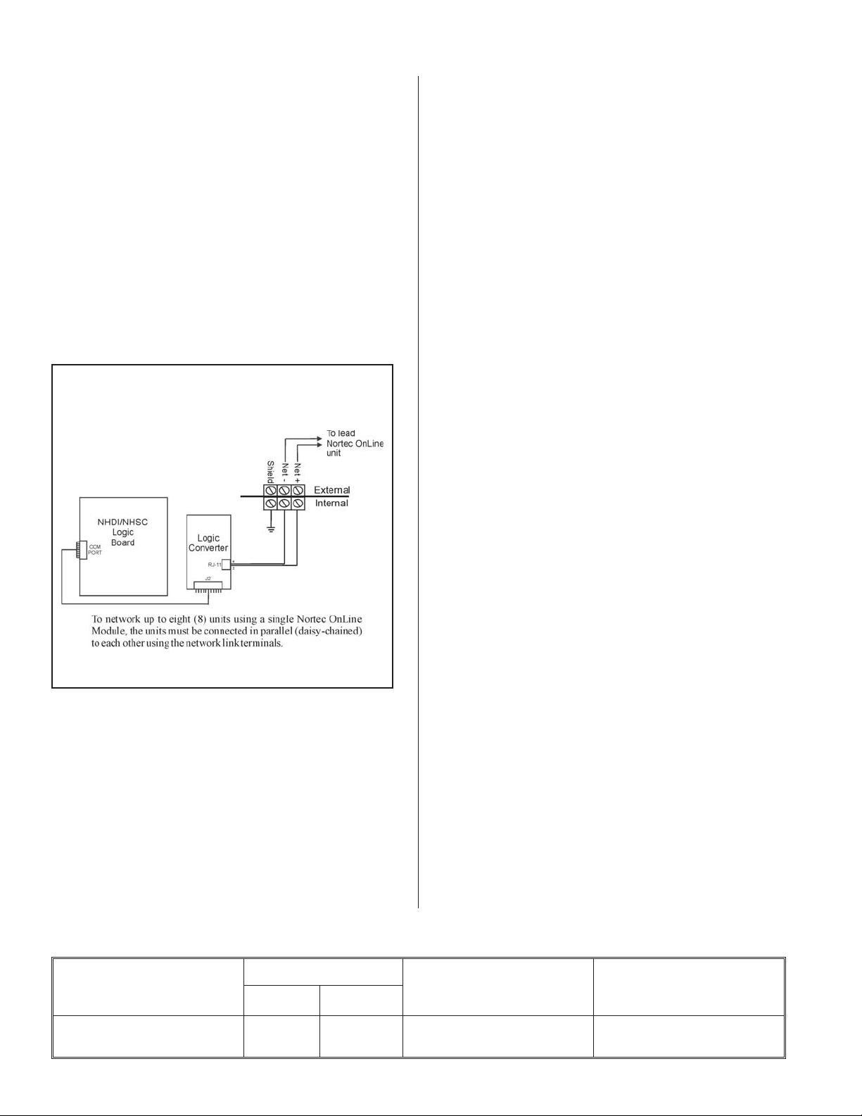
WIRING
Ethernet Connections
The necessary internal wiring for the Nortec
OnLine Module is already present except for the
Network connection that can be made internally to the
unit. To network multiple humidifiers, configured for
Nortec OnLine, simply ‘daisy-chain’ them to each other
at the network terminal strip, provided with the
humidifier (Figure #2).
Figure #2
Connecting Multiple Humidifiers to a Lead
Humidifier
The Nortec OnLine Module has been designed
and tested to operate with a variety of third-party
manufacturers equipment that promote wireless
connectivity. Should a user desire to connect the
OnLine Module to the internet via a wireless
connection such as 802.11b or g class network, Nortec
can provide recommendations on which equipment to
use.
GPRS or Dial-up Connections
The Nortec OnLine Module is also able to connect
with the Nortec Server via a dial-up connection to a
local Internet Service Provider or even through a
GPRS connection. Should such a connection be
desirable Nortec can recommend a variety of third
party manufacturers equipment that the Nortec OnLine
Module has been proven to work well with.
If a dial-up or GPRS connection is desired it will be
necessary to contact Nortec at the time of order to
provide information on the required settings.
VARIABLE DEFINITION
Table #1 refers to the recommended wire types
and maximum recommended lengths from the Nortec
OnLine Module. Since communication between the
humidifiers and Nortec OnLine will always occur via a
EIA-485 signal type, Nortec recommends using 18-24
AWG shielded, twisted pair wire between the lead
humidifier and each of the secondary humidifiers.
Cable runs between the Nortec OnLine Module and
the furthest slave humidifier should not exceed 2,600
feet. Signal boosters or repeaters may be necessary
for longer wire runs.
Nortec OnLine is capable of monitoring dozens of
control variables present in a Nortec humidifier. By
providing the data values to these variables on a
remote platform, Nortec OnLine simplifies the
troubleshooting.
Table #1
Recommended Wire Types and Lengths
Polarity
Signal Type
EIA-485, 2-wire Net + Net - 18-24 AWG Shielded,
AB
Recommended Cable
Twisted Pair
-2-
Maximum Recommended
Distance from
Nortec Module
2,600 ft.
Page 5
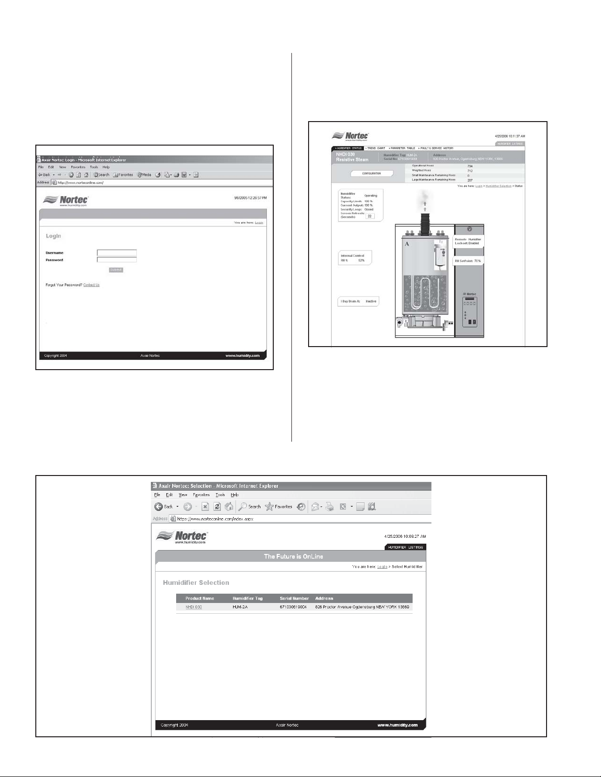
USER WEBPAGE INTERFACE
The Nortec OnLine web page can be accessed via
the internet address www.norteconline.com.
Figure #3
Nortec OnLine Homepage
By clicking on the humidifier name, the user will
then be brought to a status screen with an image of
the selected humidifier. (Refer to Figure #5).
Figure #5
Status Screen
After initially logging into the Nortec OnLine server
the user will be presented with a list of humidifiers
currently registered with the Server program. Each
humidifier will be listed with a unit type identifier, a
serial number and an address descriptor.
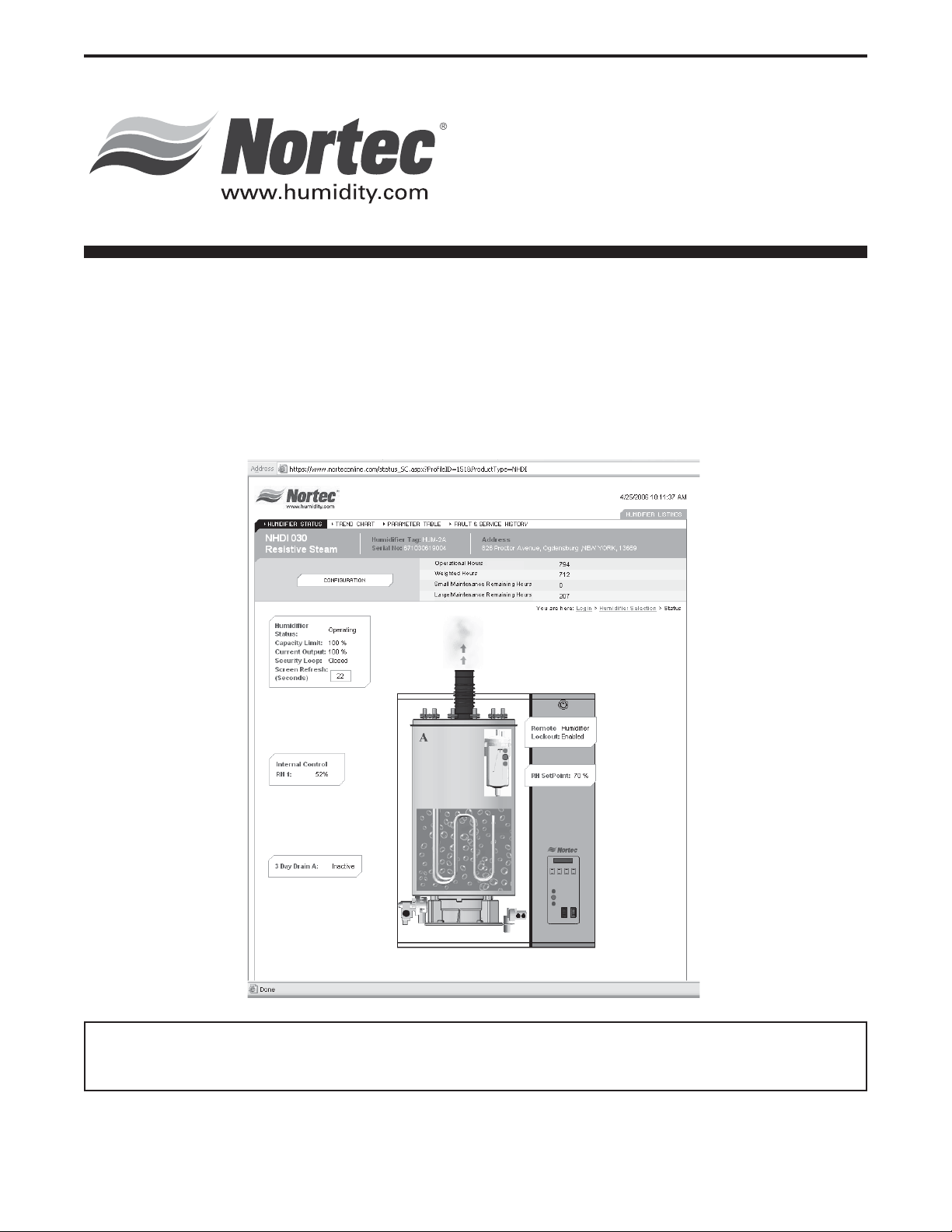
The status screen (Refer to Figure #6) provides
the user with a quick reference to the unit’s operation.
Several key status values can be gathered at a
glance. Refer to Table #2 for a description of the
variables displayed on the status screen.
Figure #4
List of Humidifiers
-3-
Page 6

Figure #6
Status Screen
Table #2
Status Screen Variables
Variable Name Displayed
Information
3 Day Drain On/Off Chart Item Indicates if the three day tank drain feature is enabled. X X
Capacity Limit 0-100% Chart Item Indicates the current value for the capacity limit set point
Channel 1
Demand%RH
Channel 1
Setpoint
Channel 2
Demand/%RH
Channel 2
Setpoint
Drain Valve
Status
0-100% Chart Item Indicates the current Demand or %RH signal being sup
0-100% Chart Item Shows current value for the setpoint of channel 1. This
0-100% Chart Item Indicates the current Demand or %RH signal supplied to
0-100% Chart Item Shows current value for the setpoint of channel 2. This
On/Off Animated Indicates when the tank drain has been activated and
Description Product Line
NHSC NHDI
XX
(adjustment) on the humidifier.
-
XX
plied to Channel 1 of the humidifier from a
connected sensor.
XX
value is only applicable when unit is set to respond to a
%RH signal.
XX
Channel 2 of the humidifier from a connected sensor.
XX
value is only applicable when unit is set to respond to a
%RH signal and configured for dual channel.
XX
the unit is draining water.
Fault Indicator On/Off Lamp
Indicator
Fill Valve Status On/Off Animated Indicates if the humidifier is filling the water tank. X X
Provides current fault status. The red fault light is lit
when a fault is detected.
-4-
XX
Page 7

Variable Name Displayed
Information
Table #2
Status Screen Variables - CONTINUED
Description
Product Line
NHSC NHDI
Full Tank
Blowdown
On/Off Chart Item Indicates if the full tank blowdown feature is enabled or
disabled. Feature is toggled by dip-switch on
mainboard.
Keep Warm
[Keep Warm used
on status screen
On/Off Chart Item Indicates if the water tank keepwarm feature is enabled
or disabled. Feature is toggled by dip-switch on
mainboard
not Keep Warm.]
Operational Hours Hours Chart Item Displays the amount of the time the humidifier has been
in operation.
Remaining Service
Hours. Hours to
Hours Chart Item Displays the number of operational hours left until the
next suggested service period is due.
next Service.
Serial Number Alpha-Numeric
String
Service Indicator On/Off Lamp
Indicator
Software Version Numerical Chart
Item
Indicates the Humidifiers Serial Number for quick
reference.
Provides current service status. The yellow service light
is lit when service is due.
Indicates the software version installed on the
Humidifiers mainboard
Steam Production On/Off Animated Indicates that the humidifier is producing steam in
response to a demand signal.
System Demand
Correct Output
0-100% Numerical
Data
Displays the humidifier's current demand output X X
XX
XX
XX
XX
XX
XX
XX
XX
Unit Address Mailing Address
Provides details on the Humidifier's location. X X
Chart Item
Unit Model Unit Identifier Chart
Item
Unit Status On/Off Lamp
Indicator
Water Level High On/Off Lamp
Indicator
Water Level
Mid-Range
On/Off Lamp
Indicator
Water Level Low On/Off
Lamp Indicator
Indicates the model type & size of the selected
Humidifier.
Indicates if unit has responded to a demand signal. The
green LED is on when a demand signal is present.
Yellow light is on if water is at a high level. Light
combinations are possible for mid-state water levels.
Green light is on if water is at optimal level. Light
combinations are possible for mid-state water levels
Red light is on if water is at a low level. Light
combinations are possible for mid-state water levels.
Weighted Hours Hours Chart Item Equivalent operating hours convelated to 100% steam
production, e.g. Weighted hours = 2 hours at 50%
demand.
XX
XX
XX
XX
XX
XX
-5-
Page 8

Configuration Screen
By selecting the Configuration button
(see Figure #7 & Figure #8) located near the top of the
webpage, the user is able to adjust control parameters
for the humidifier.
Table #3 provides a description of the control
variables provided to the user.
Configuration Screen
Figure #7
Configuration Button
Figure #8
-6-
Page 9

Table #3
Control Variables
Variable Name Setting Range Description Product Line
NHSC NHDI
Limited Capacity 0-100% Allows the user to adjust the total
steam output the unit will be able to
produce at 100% demand.
Relative Humidity
Setpoint
0-100% Sets the Channel 1 Setpoint. This fea
ture is only enabled when the humidi
fier is set to operate with an RH signal.
Relative Humidity
Setpoint 2
0-100% Sets the Channel 2 Setpoint. This fea
ture is only enabled when the humidi
fier is set to operate with an RH signal.
Remote Lockout Humidifier Enabled /
Humidifier Disabled
Forces the humidifier into a lockout
state where steam production is halted
and the unit will not respond to any de
mand input.
XX
-
XX
-
-
XX
-
XX
-
-7-
Page 10

At the top of the screen the user is presented with
options for three different screens (see Figure #9).
One option will provide a trending graph (See
Figure #10) that monitors points such as
%RH/Demand and setpoint settings for channel 1 and
channel 2 as well as the current humidifier’s output.
This trend graph is capable of keeping historical data
for each particular unit.
Figure #9
Three Screen Options
Figure #10
Trend Data
The Fault and Service History link (See Figure
#11) provides a list of up to 18 fault or service errors
that the humidifier has experienced . This can provide
valuable troubleshooting information when faced with
a recurring problem.
The Parameter link (See Figure #12) provides an
in-depth view of all the variables available through
Nortec OnLine. From the parameter listings a user can
determine if the proportional coefficient for the PI band
on channel 1, or even what version of software the unit
is currently operating with.
-8-
Page 11

Figure #11
Fault and Service History
Figure #12
Parameter Link
-9-
Page 12

NORTEC ONLINE START-UP
CHECKLIST
Wiring:
Humidifier-to-Humidifier Connection:
r Each individual Humidifier linked to lead Unit
r Connection can be direct or daisy-chained to
other units
Network Connection:
r Lead Unit wired to Local Network (Ethernet,
GPRS, Dial-up) :
r Network activity verified
Controls Wired:
r Directly to humidifiers:
Start-Up Procedure:
r Ensure power is being supplied to the humidifier
and Nortec OnLine Module.
r Verify power to Nortec On-Line Module (Power
LED should be lit).
r After power-up, verify network communication.
r Verify variable operation after mapping is
complete.
r Perform regular humidifier start-up check.
Troubleshooting:
Nortec OnLine Module Indicator Lights:
The OnLine Module has four status indicator LEDs
that provide a quick-reference for troubleshooting
communication faults with the Nortec OnLine option.
Table 2 provides a description of each LEDs function.
-10-
Page 13

Table #4
Nortec OnLine Module Status LED Description
LED Name Color Function
Module Status Off Indicates that the OnLine Module is not receiving power.
Green Indicates the OnLine is operating normally.
Orange Indicates that the OnLine is loading the firmware installed on
the module.
Serial Link Status Flashing Greed Indicates that the OnLine is receiving a network packet from
an serial connection.
Flashing Red Indicates that the OnLine is transmitting a network packet on
a serial connection.
Orange Displayed when the OnLine is booting.
Ethernet Activity / Collision Flashing Green Indicates that the OnLine is receiving a network packet from
an Ethernet connection.
Flashing Red Indicates that the OnLine is transmitting a network packet on
a Ethernet connection.
Network Link Off No network connection is present.
Green The OnLine has detected the presence of a 10Mbps network.
Orange The OnLine has detected the presence of a 100Mbps net-
Troubleshooting Communication Problems
Problem Solution
1. The Nortec OnLine server
cannot read/write any
information to any of the
networked humidifiers.
Verify that the network connection is made and is connected
properly.
Verify that the correct network settings are being used. The Nortec
OnLine Module may need to be restarted to load the new settings.
Check the Ethernet Link (if Ethernet enabled) or Serial Link (if
modem enabled) communication LED's to determine if there is any
network traffic being sent or received by the Nortec OnLine Module
from the Nortec OnLine Server.
Verify proper connections to networked humidifiers.
Turn the Nortec OnLine Module off for several seconds then switch it
back on to reload the control program. Allow for some time for the
network variables to be polled.
work.
Table #5
2. The Nortec OnLine Server
network can see some of the
networked humidifiers but not
others.
Ensure proper connections to the humidifiers.
Disconnect all of the humidifiers from the Nortec OnLine Module
except for the unit that is not responding to the network. Disconnect
power to the Nortec OnLine Module, wait a moment, then reconnect
power. Check Serial Link LED transmit/receive lights to see if the
module can talk to the humidifier.
-11-
Page 14

SPARE PARTS
Part Number Item Description
1509602 Nortec OnLine Module -
Dial-up Config
1509603 Nortec OnLine Module -
GPRS Configuration
1509604 Nortec OnLine Module -
Static IP Configuration
1509605 Nortec OnLine Module -
DHCP Configuration
2520669 Y-Adapter Cable OnLine Module to Converter.
2520670 Header Cable Converter to humidifier cable.
2520727 RS 232/485/TTL Converter
Spare part for Nortec OnLine Module
with dial-up settings.
Spare part for Nortec OnLine Module
with dial-up settings.
Spare part for Nortec OnLine Module
with wired ethernet and static IP
settings.
Spare part for Nortec OnLine Module
with wired ethernet and dynamic IP
settings.
-12-
Page 15

LIMITED WARRANTY
AXAIR NORTEC INC. and/or AXAIR NORTEC LTD. (hereinafter collectively referred
to as THE COMPANY), warrant for a period of two years from date of shipment, that
THE COMPANY’s manufactured and assembled products, not otherwise expressly
warranted, are free from defects in material and workmanship. No warranty is made
against corrosion, deterioration, or suitability of substituted materials used as a result of
compliance with government regulations.
THE COMPANY’s obligations and liabilities under this warranty are limited to
furnishing replacement parts to the customer, F.O.B. THE COMPANY’s factory,
providing the defective part(s) is returned freight prepaid by the customer. Parts used
for repairs are warranted for the balance of the term of the warranty on the original
humidifier or 90 days, whichever is longer.
The warranties set forth herein are in lieu of all other warranties expressed or
implied by law. No liability whatsoever shall be attached to THE COMPANY until said
products have been paid for in full and then said liability shall be limited to the original
purchase price for the product. Any further warranty must be in writing, signed by an
officer of THE COMPANY.
THE COMPANY’s limited warranty on accessories, not of AXAIR NORTEC’s
manufacture, such as controls, humidistats, pumps, etc. is limited to the warranty of the
original equipment manufacturer from date of original shipment of humidifier.
THE COMPANY makes no warranty and assumes no liability unless the equipment
is installed in strict accordance with a copy of the catalog and installation manual in
effect at the date of purchase and by a contractor approved by THE COMPANY to
install such equipment.
THE COMPANY makes no warranty and assumes no liability whatsoever for
consequential damage or damage resulting directly from misapplication, incorrect sizing
or lack of proper maintenance of the equipment.
THE COMPANY retains the right to change the design, specification and
performance criteria of its products without notice or obligation.
Page 16

- www.humidity.com -
U.S.A. - AxAir NORTEC Inc. 826 Proctor Avenue, Ogdensburg, New York, 13669
CANADA - AxAir NORTEC Ltd. 2740 Fenton Road, Ottawa, ON, K1T 3T7
1-(866) NORTEC-1 Fax - (613) 822-7964
A WMH COMPANY
PRINTED IN CANADA
 Loading...