

Page 1
Important: Read and save these instructions. This guide to be left with equipment.
2530618-J | 10 NOV 2014
NH
Series
Installation and
Operation Manual
Includes installation, operation
maintenance and troubleshooting
information for your NHRS Resistive
Element Steam Humidifier
Page 2

INSTALLATION DATE (MM/DD/YYYY)
MODEL #
SERIAL #
Thank you for choosing NORTEC.
Proprietary Notice
This document and the information disclosed herein are proprietary data of Nortec Humidity Ltd. Neither this
document nor the information contained herein shall be reproduced, used, or disclosed to others without the
written authorization of Nortec Humidity Ltd., except to the extent required for installation or maintenance of
recipient’s equipment.
Liability Notice
Nortec does not accept any liability for installations of humidity equipment installed by unqualified personnel,
or the use of parts/components/equipment that are not authorized or approved by Nortec.
Copyright Notice
Copyright 2014, Nortec Humidity Ltd. All rights reserved.
Page 3

Contents
1 Introduction
2 Receiving and Unpacking
3 Humidifier Components
4 Description of Components
5 NHRS Models
8 Installation
9 Typical Humidifier Installation
10 Location
12 Mounting with Keyholes
13 Plumbing
14 Steam Distributor
15 Steam Lines and Condensate
Return
21 Electrical
22 External Controls
29 Optional Outdoor Temperature
Setback Sensor
30 Remote Fault Option Wiring
31 Options and Accessories
36 Start Up Procedure
38 Information Screens
45 How the Humidifier Works
47 Selecting an RH Setpoint
48 Maintenance and
Servicing
52 Troubleshooting
53 General Troubleshooting
55 Wiring Diagrams
57 Start Up Checklists
60 Maintenance Checklists
61 Spare Parts
62 NHRS Plumbing Parts
64 NHRS Electrical Parts
66 Warranty
33 Start Up
34 Installation Check
Page 4
CAUTION: Servicing
Disconnect main power before any servicing.
The plumbing and electrical compartments contain high voltage components and
wiring. Access should be limited to authorized personnel only.
During and following operation of the humidifier, the steam and components in
contact with the steam such as the cylinder, blower pack, steam lines, steam
distributors, and condensate lines can become hot and can burn if touched.
Nortec Humidity Ltd. does not accept any liability for installations of humidity
equipment installed by unqualified personnel or the use of parts/components /
equipment that are not authorized or approved by Nortec Humidity Ltd.
CAUTION: Electrical
All electrical work should be done according to local electrical code.
Electrical connection to be performed by a licensed electrician.
CAUTION: Plumbing
Plumbing to be performed by a licensed plumber.
Drain water from humidifier can be very hot. Do not drain to public sink.
All plumbing work should be done according to local plumbing code.
CAUTION: Installation
Do not mount on hot surfaces.
Do not mount in area where freezing can occur.
Do not mount on vibrating surface.
Do not mount on floor.
The NHRS produces steam at atmospheric pressure, no devices which could block
steam output should be connected to the steam outlet.
Steam lines must be installed so that no restriction can produce backpressure in
the humidifier. Failure to follow installation instructions will result in improper
operation and could void warranty.
Regardless of selecting On/Off or modulating control method, NORTEC humidifiers
must have a closed circuit across the On/Off security loop control terminal to
operate. NORTEC highly recommends the use of a high limit humidistat and an air
proving switch in series for this function.
Introduction
1 | Introduction
Page 5
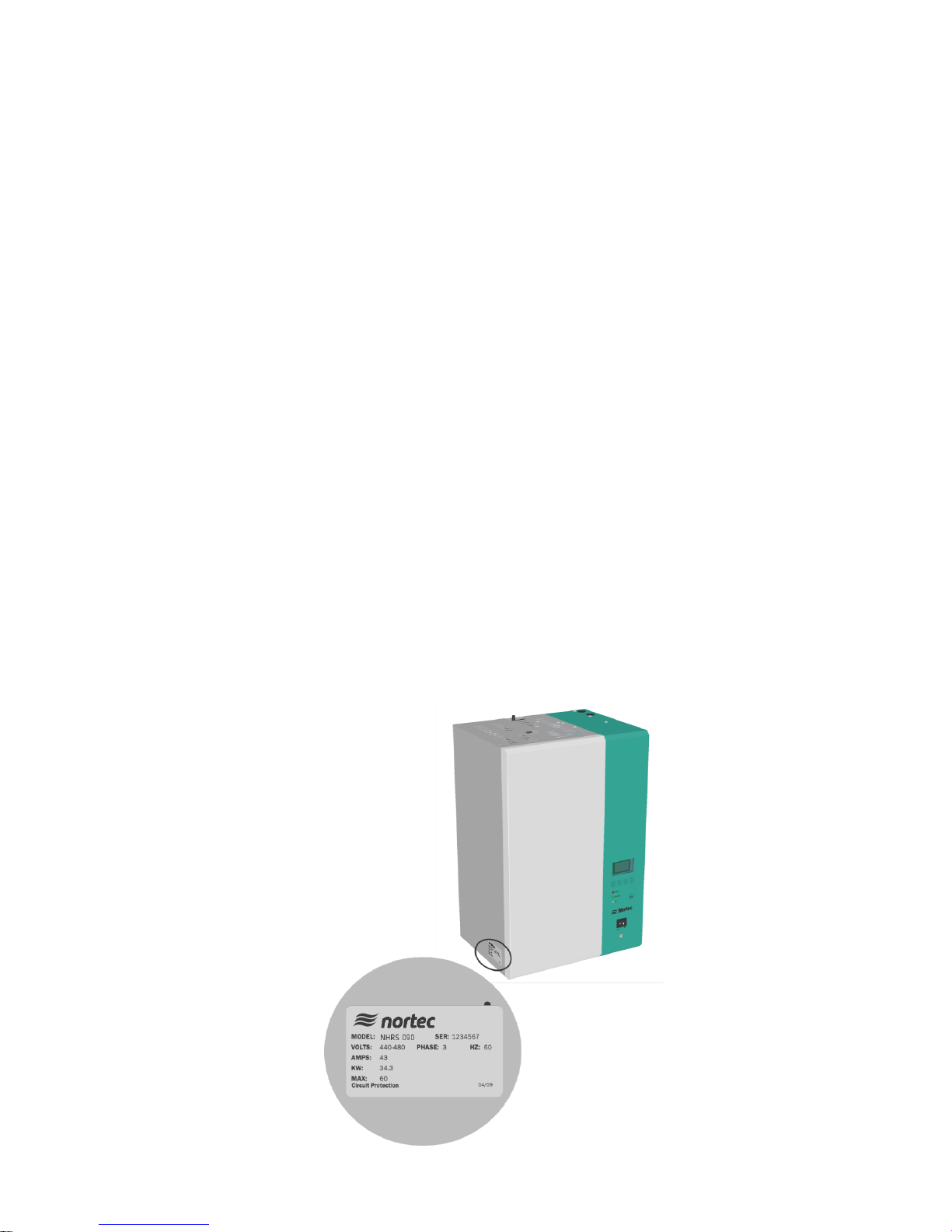
Figure 1: Specification Label Location
Receiving and Unpacking
1 Check packing slip to ensure ALL material has been delivered.
2 All material shortages are to be reported to NORTEC within 48 hours from receipt of goods.
NORTEC assumes no responsibility for any material shortages beyond this period.
3 Inspect shipping boxes for damage and note damages on shipping waybill accordingly.
4 After unpacking, inspect equipment for damage. If damage is found, notify the shipper
promptly.
5 All NORTEC products are shipped on a Free-On-Board (FOB) factory basis. Any and all
damage, breakage or loss claims are to be made directly to the shipping company.
Before Installation
1 Ensure that available voltage and phase corresponds with humidifier voltage and phase as
indicated on humidifier specification label.
2 Ensure that the dedicated external fuse disconnect is of sufficient size to handle the rated
amps as indicated on the specification label. Refer to local codes.
3 Report any discrepancy immediately to the site engineer.
4 Ensure sufficient clearances will be available as described on pages 10 and 11.
5 Ensure steam lines can be routed to distributor or blower pack as described on pages 14-19
and 31.
Introduction | 2
Page 6
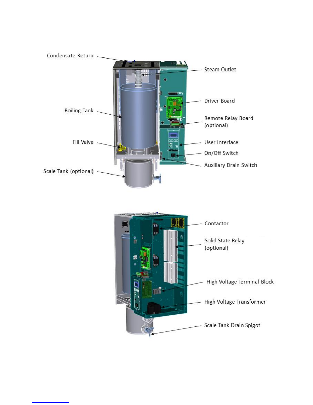
Humidifier Components
3 | Introduction
Figure 2: NHRS Humidifier Components
Page 7

Component
Function of Component
Auxiliary Drain
Switch
Drains water from boiling tank by activating drain pump. Note that initiating a
drain in this manner will not induct Drain Water Cooling.
Boiling Tank
Holds resistive elements submerged in water. Current traveling along the
internal element wire generates heat which is used to generate steam.
Condensate
Return
Provides a connection to return condensate to humidifier.
Contactor
Turns On/Off power to boiling tank elements.
Drain Pump
Drains water from boiling tank.
Drain Water
Cooling Valve
Adds cold supply water to water draining from boiling tank to temper drain
water to a maximum of 140ºF (60ºC).
Driver Board
Provides input and output connections to humidifier components.
Fill Cup
Provides an air gap for backflow prevention.
Fill Valve
Controls flow of water into humidifier.
High Voltage
Terminal Block
Primary power connection from remote disconnect to humidifier.
High Voltage
Transformer
Steps primary voltage down to 24 VAC for the controller and internal
components such as the fill valve and drain pump.
On/Off Switch
Turns power On/Off to humidifier controller. Note: Turn off humidifier
disconnect to shut off primary power to the humidifier.
Remote Relay
Board (option)
Provides a terminal strip to dry contacts which open/close to indicate the
humidifier is on, humidifying, needs service, or is in a fault condition.
Scale Tank
Scale created inside the boiling tank (on the elements and the side walls)
breaks off and gravitates to the scale tank for easy disposal.
Scale Tank
Drain Spigot
Manually activated drain spigot used to empty the scale tank of water before
removing and emptying tank of collected scale.
Solid State
Relay (optional)
Solid State Relays offer shorter cycles when turning the resistive elements On
and Off. Recommended for humidification applications requiring high
accuracy.
Steam Outlet
Connect to steam line with steam hose.
User Interface
Controls all functions of the humidifier operation and provides user ability to
modify configuration of the humidifier.
Description of Components
Table 1: Humidifier Components
Introduction | 4
Page 8

NHRS Models
The NHRS is Nortec’s flagship resistive element electric humidifier. Since it can accept a variety
of supply water types (potable, Reverse Osmosis, De-Ionized), it is very robust and useful in a
wide set of applications. The NHRS is available in capacities ranging from 10 lb/hr (4.5 kg/hr)
to 180 lb/hr (81.6 kg/hr). NHRS humidifiers are packaged in two different cabinets, depending
on their capacity. Figure 3 shows the configuration and relative size of the different cabinets.
Table 3 on page 7 provides specifications for the NHRS product line.
Figure 3: NHRS Models
Double Unit (NHRS 135-180)
NHRS double units have two tanks to provide increased capacity. The construction and
installation of double units is identical to units with a single tank with the following exceptions:
In addition to having two tanks, double units also have two Driver Boards. One Driver
Board controls each tank.
Double units can operate both tanks in series or parallel from a single control signal
Parallel Operation – If configured for parallel operation, only one set of control wiring is
required. The tanks operate in parallel giving the advantage of even wear on both tanks.
Series Operation – One tank’s output range is 0-50% and the other tank’s output range
is 50-100%. An advantage is that a lower turndown ratio can be applied to one tank.
Hybrid Mode – One tank operates using Solid State Relay switching, the other tank
operates using contactor switching. See P/N 2530631.
Double units have one primary power connection, but have individual fill, drain, and
steam outlet connections for each tank.
5 | Introduction
Page 9

Component
Function of Component
Drain Water
Cooler, Low
Flow
Reduces drain rate from the humidifier by restricting the boiling tank drain
outlet diameter, as well as providing a lower-flow drain water cooling valve.
Dual Demand
Controller
Consists of a universal math module that compares two demand input signals
and outputs the lowest of the two to the humidifier. This option is useful
where a high limit modulating demand channel is desired (along with a
modulating demand channel humidistat), since the humidifier only allows one
modulating input. See P/N 2558776.
Keep Warm
(Outdoor
standard)
Maintains water temperature in boiling tank at 160ºF (70ºC) for quick
response of the unit to a call for humidity while minimizing health concerns
associated with standing water. See P/N 1504561.
Nortec
Online/LINKS2
Provides monitoring and control, allowing humidifier to communicate with a
Building Management System (BMS). Controller is factory installed and
located internally to the humidifier. At the time of ordering, customer must
specify the desired protocol: BACnet/IP, BACnet/MSTP, Johnson N2, or
LonWorks.
Nortec Online provides an internet-based monitoring and control system for
the humidifier.
Remote Relay
Board
Provides four built-in status relays for remote monitoring capabilities: steam
production, unit fault, maintenance/service, and unit power. Relays can
interface with a Building Management System (BMS). If one of the above
conditions is met, a relay will close which will complete a connection. A signal
will be provided to a wire terminal. See P/N 1508069.
Scale
Management
System
Provides a separate reservoir underneath boiling tank for scale collection.
Minerals removed from the boiling tank water during steam production will
collect in the scale reservoir rather than in the tank. When minor
maintenance is needed, the scale tank is easily removed and emptied.
Solid State
Relays
Allow for rapid response upon call for humidity, adapting instantly to humidity
demand, allowing for tight control of the in-space humidity.
Outdoor Model
The NHRS is available for outdoor use, providing a weatherproof enclosure that allows for
installation on rooftops in relatively extreme climates. Refer to the installation addendum that
is provided with the NHRS Outdoor model to ensure proper installation (P/N 2531550).
Options and Accessories
Nortec provides a complete line of options and accessories for every humidification application.
The following options and accessories are available and may have been delivered with your
NHRS humidifier. Refer to the installation instructions that came with the accessories for
proper installation and operation.
Table 2: Options and Accessories
Introduction | 6
Page 10
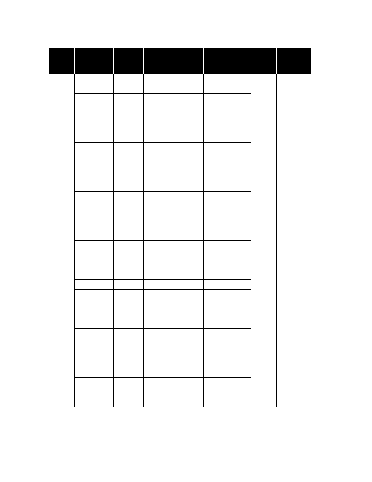
Phase
Capacity
lb/hr (kg/hr)
Volts
NHRS Part
No.
Amps
Max
Ext
Fuse
kW
Fill
gpm
(l/min)
Net/Full
Weight lb
(kg)
1
10 (4.5)
208
2530540
18.4
25
3.83
3.8
(14.4)
119/190
(54/86)
10 (4.5)
220-240
2530541
15.9
20
3.83
10 (4.5)
440-480
2530542
8.0
15
3.83
10 (4.5)
550-600
2530543
6.4
15
3.83
15 (6.8)
208
2530544
24.5
35
5.10
15 (6.8)
220-240
2530545
21.3
30
5.10
15 (6.8)
440-480
2530546
10.6
15
5.10
15 (6.8)
550-600
2530547
8.5
15
5.10
20 (9.0)
208
2530548
36.8
50
7.65
20 (9.0)
220-240
2530549
31.9
40
7.65
20 (9.0)
440-480
2530550
15.9
20
7.65
20 (9.0)
550-600
2530551
12.8
20
7.65
30 (13.6)
208
2530552
49.0
70
10.20
30 (13.6)
220-240
2530553
42.5
60
10.20
30 (13.6)
440-480
2530554
21.3
30
10.20
30 (13.6)
550-600
2530555
17.0
20
10.20
3
30 (13.6)
208
2530556
31.9
40
11.48
30 (13.6)
220-240
2530557
27.6
35
11.48
30 (13.6)
440-480
2530558
13.8
20
11.48
30 (13.6)
550-600
2530559
11.1
15
11.48
45 (20.4)
208
2530560
42.5
60
15.30
45 (20.4)
220-240
2530561
36.9
50
15.30
45 (20.4)
440-480
2530562
18.4
25
15.30
45 (20.4)
550-600
2530563
14.7
20
15.30
65 (29.4)
208
2530606
63.8
80
22.98
65 (29.4)
220-240
2530609
55.3
70
22.98
65 (29.4)
440-480
2530610
27.6
35
22.95
65 (29.4)
550-600
2530611
22.1
30
22.95
90 (40.8)
440-480
2530612
36.9
50
30.60
90 (40.8)
550-600
2530613
29.5
40
30.60
135 (61.2)
440-480
2530614
55.3
70
45.90
7.6
(28.8)
186/330
(85/150)
135 (61.2)
550-600
2530615
44.2
60
45.90
180 (81.6)
440-480
2530616
73.7
100
61.20
180 (81.6)
550-600
2530617
59.0
80
61.20
Table 3: NHRS Specifications
7 | Introduction
Page 11

Installation
9 Typical Humidifier
Installation
10 Location
11 Blower Pack Clearance
Requirements
12 Mounting with Keyholes
13 Plumbing
14 Steam Distributor
15 Steam Lines and
Condensate Return
21 Electrical
22 External Controls
29 Optional Outdoor
Temperature Setback
Sensor
30 Remote Fault Option
Wiring
31 Options and Accessories
32 Keep Warm (Outdoor Standard)
32 Nortec Online/LINKS2
32 Remote Relay Board
32 Scale Management System
32 Solid State Relays
22 Control Wiring
22 Duct Humidification
23 Space Humidification
24 On/Off Control Wiring
26 Modulating Control Wiring
28 Transducer Control Wiring
Installation | 8
Page 12
Mounting
Page 10
Steam
Distribution
Page 14
Controls
Page 21
Electrical
Page 20
Plumbing
Page 13
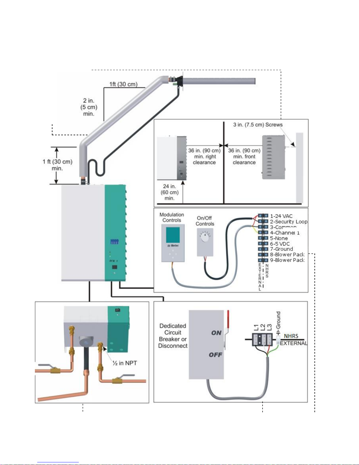
Typical Humidifier Installation
Figure 4: Typical Humidifier Installation
9 | Installation
Page 13
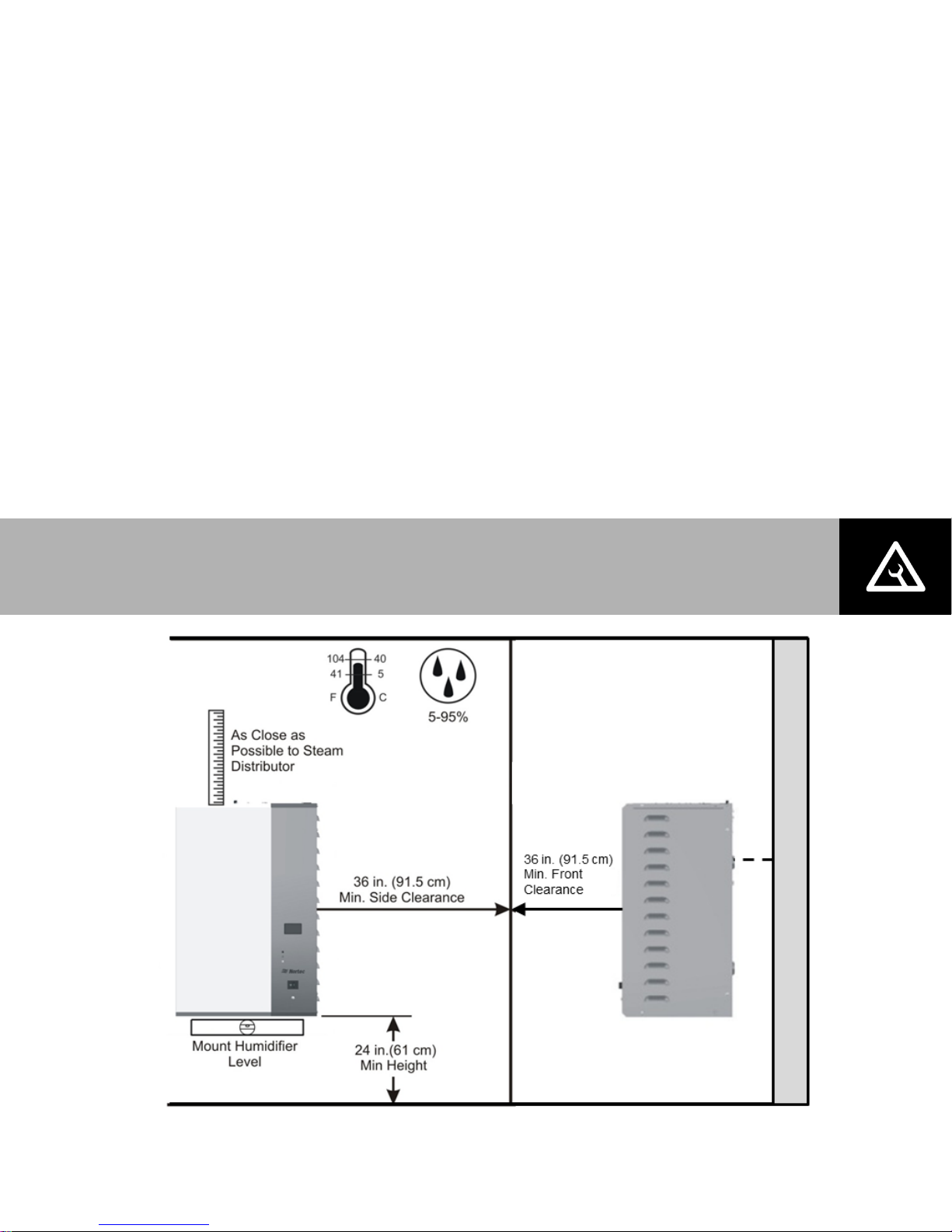
Figure 5: Mounting Location / Clearance
Note: Do not mount on hot surfaces, where freezing can occur, vibrating surfaces, or
floor.
Location
Mount on a suitable wall or vertical surface. Do not sit the unit on the floor to allow
clearances required for plumbing and electrical connections.
Clearance dimensions shown are for reference only and are the minimum required for
maintenance of the humidifier. Consult local and national codes before final location
and installation. Nortec does not accept responsibility for installation code violations.
Install only in areas with ambient temperatures between 41 and 104ºF (5 and 40ºC),
and relative humidity between 5 and 95% (non-condensing).
When possible, install the humidifier below the steam distributor. If mounted above the
steam distributor, take care to provide proper steam line routing and proper condensate
traps.
DO NOT locate the humidifier any further than absolutely necessary from the steam
distributor location as net output will be reduced as a result of heat loss through the
steam line.
When possible, mount the humidifier at a height convenient for servicing.
Installation | 10
Page 14
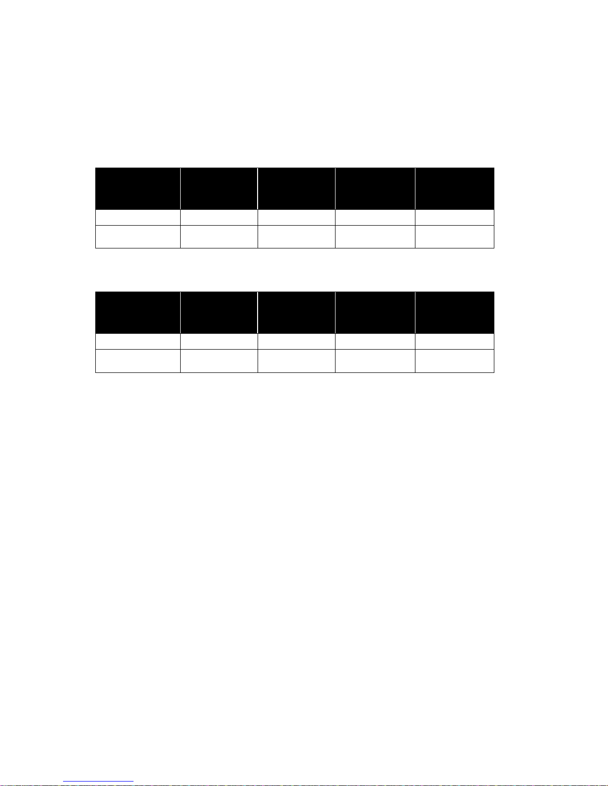
Humidifier
Capacity
lb/hr (kg/hr)
Min. Frontal
Clearance
Inches (cm)
Min. Overhead
Clearance
Inches (cm)
Min. Left Side
Clearance
Inches (cm)
Min. Right Side
Clearance
Inches (cm)
Up to 30 (13.6)
132 (336)
12 (31)
12 (31)
12 (31)
30-100
(13.6-45.4)
Not
recommended
Not
recommended
Not
recommended
Not
recommended
Blower Pack Clearance Requirements
For more information regarding the clearance requirements of the Remote Mounted Blower
Pack (P/N 2572615), refer to installation manual (document number 2572641).
Table 4: Clearances for Blower Packs on Low Speed*
Table 5: Clearances for Blower Packs on High Speed*
*NOTES:
Nominal Conditions: 72ºF (22.2ºC), 43% RH.
Low speed not recommended for 50-100 lb/hr humidifiers.
Blower Pack should not be installed near cold surfaces or where dew point may be reached.
Higher humidity or lower room temperature may result in longer absorption distances.
11 | Installation
Page 15

Note: Use screws longer than 3” (7.5 cm) if drywall or other spacer is present.
Mounting with Keyholes
1. The NHRS Series humidifier is wall mounted using keyholes located on the back of the
unit cabinetry.
2. Use #12 x 3” (7.5 cm) screws mounted into 2x4” studs or better. Two screws are
required for units with one tank (NHRS 10 to NHRS 90 lb/hr). Three screws are required
for units with two tanks (NHRS 135 and 180 lb/hr).
3. Keyholes are spaced 16” (40.6 cm) apart center to center as per UL certification
standard stud spacing dictates. Insert screws into the studs until there is ¼” (0.6 cm) of
screw exposed. Ensure the screws are level to each other.
4. Raise the unit and place the screws through the keyholes. Make sure the unit is level
before tightening the screws to secure the unit in place.
5. Place L-shaped brackets on top of the unit, ensuring the holes are in-line with the studs.
Using the appropriate sized wood screw, fasten the L-brackets to the studs, securing the
unit from any upwards motion. See Figure 6.
Figure 6: Mounting with Keyholes; A = B = 16” (40.6 cm)
Installation | 12
Page 16

Note: • Drain water is very hot, do not drain to public sink.
• Use material suitable for 212ºF (100ºC) for drain and condensate lines.
Figure 7: Water Supply and Drain Connection
Plumbing
All water supply and drain line connections should be installed in accordance with local
plumbing codes.
Supply water should have pressure between 30 and 80 psi
between 0 and 12 gr/gal. Various types of supply water may be used: soft water, deionized, reverse osmosis, or potable.
Install water shut-off valve and union before humidifier to facilitate servicing.
The drain line should not end in a sink used frequently by personnel, or where plumbing
codes prohibit. Route to a floor drain or equivalent for safety reasons.
Ensure drain line is adequately sized to provide free and easy draining. Ensure air gap is
installed as shown. A restricted drain can cause the boiling tank to become heavily
concentrated with minerals and may result in poor operation or water backing up at the
air gap.
and have a hardness
g
13 | Installation
Page 17
• Install the NHRS as close as possible to whatever steam distributor is used.
• Refer to distributor, SAM-e, or Remote Blower Pack installation manuals for detailed
installation instructions (2556592, 1507619, and 2572641, respectively)
Steam Distributor
Steam generated by the NHRS may be distributed directly into a conditioned
environment with a Remote Blower Pack (P/N 2572615), or into an air handling system
using either Nortec steam distributors or Nortec’s SAM-e steam distribution manifold.
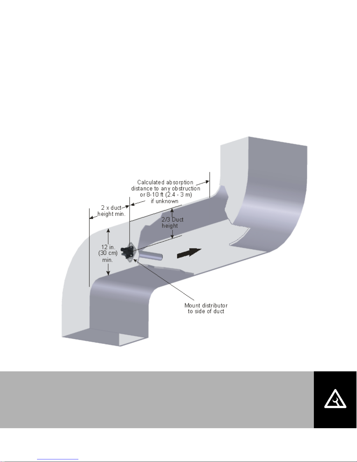
The steam distributor should be installed as close as possible to the humidifier. Short
steam distribution lines minimize condensate losses and the possibility of generating
back pressure in the steam distribution line.
Figure 8 provides common guidelines for locating a steam distributor in a duct.
Figure 8: Distributor Location in Duct
Installation | 14
Page 18
NHRS
Unit
Size
Steam
Output
(lbs/hr)
Distance
ft (m)
Possible
Loss
ft (m)
Steam
Line
Size
010
10
15 (4.5)
2 (0.6)
1.5”
015
15
17.5 (5)
2.25 (0.7)
020
20
20 (6)
2.5 (0.8)
030
30
25 (7.5)
3 (0.9)
045
45
35 (10.5)
4 to 5 (1.2 to 1.5)
065
65
45 (13.5)
5 to 10
(1.5 to 3.0)
090
90
50 (15)
135
135
50/tank (15)
2 x 1.5”
180
180
50/tank (15)
NOTES:
1) This chart gives the maximum length of recommended steam line by unit size.
2) The use of steam line other than copper, stainless steel, or Nortec steam hose will void the
warranty and may cause adverse effects regarding the operation of the humidifier.
3) Nortec steam line shall only be used for steam line runs of 10 ft (3m) or less.
4) Long steam runs affect accuracy of humidifier and its ability to quickly respond to changes in
demand. When tight control is required, ensure steam line run is as short as possible.
5) NHRS 135 and 180 have two tanks.
Danger:
The NHRS is an atmospheric humidifier that will only operate properly when its steam
distribution system is installed so that it provides no significant backpressure.
Installing the NHRS in such a way that backpressure can develop during operation
could result in serious injury or damage to property.
Steam Lines and Condensate Return
The following instructions must be followed for installation of steam lines for ASD, BSD, CSD,
SAM-e, and Remote Blower Packs. Failure to used material in Table 6 and Table 7 on page 16,
or failure to follow any other steam line installation instructions, will result in improper operation
and could void warranty.
Table 6: Recommended Maximum Length of Steam Line
15 | Installation
Page 19

Supply
Water
Type
Tank Size
(lbs/hr)
Steam Run
ft (m)
Steam Line
Material
Steam Line
Description
Potable
0-30
0-10 (0-3)
Copper Tube
1.5” MED-L Tubing
(1.625” OD)
0-30
10-30 (3+)
Copper Tube
2.0” MED-L Tubing
(2.125” OD)
RO or
DI
0-30
0-10 (0-3)
Stainless Steel Tube
1.75” Tube x
0.065” thick
0-30
10-30 (3+)
Stainless Steel Tube
2.0” Tube x
0.065” thick
Potable
45-90
0-20 (0-6)
Copper Tube
1.5” MED-L Tubing
(1.625” OD)
45-90
20+ (6+)
Copper Tube
2.0” MED-L Tubing
(2.125” OD)
RO or
DI
45-90
0-20 (0-6)
Stainless Steel Tube
1.75” Tube x
0.065” thick
45-90
20+ (6+)
Stainless Steel Tube
2.0” Tube x
0.065” thick
Table 7: Recommended Materials and Sizes for Steam Runs.
Installation | 16
Page 20
Ste
am
D
irectio
n
Ste
a
m Dir
ectio
n
S
t
e
a
m
D
i
r
e
c
t
i
o
n
2 in.
(5 cm)
1 ft (30 cm)
1ft (30 cm)
0.5 in.
(12 mm)
10 Degrees
2 Degrees
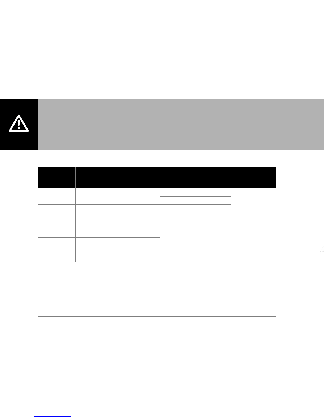
Use Appropriate Slope Insulate Pipe
1 in. (2.5 cm) pipe
insulation
Minimal Slope (up)
Minimal Slope (down)
Figure 9: Steam Line Slope and Installation
• Trap at all low points and recommended intervals using full size ‘T’ for traps.
• Condensate should not be routed to a sink used frequently by personnel. Route to a floor
drain or equivalent. Condensate normally cools in traps but is still hot. A SAM-e or larger
steam line generates more condensate and water may not cool in the trap. A drain water
cooler option may be installed if required by code.
• Route condensate to floor drain or equivalent in multi-unit to single SAM-e installation.
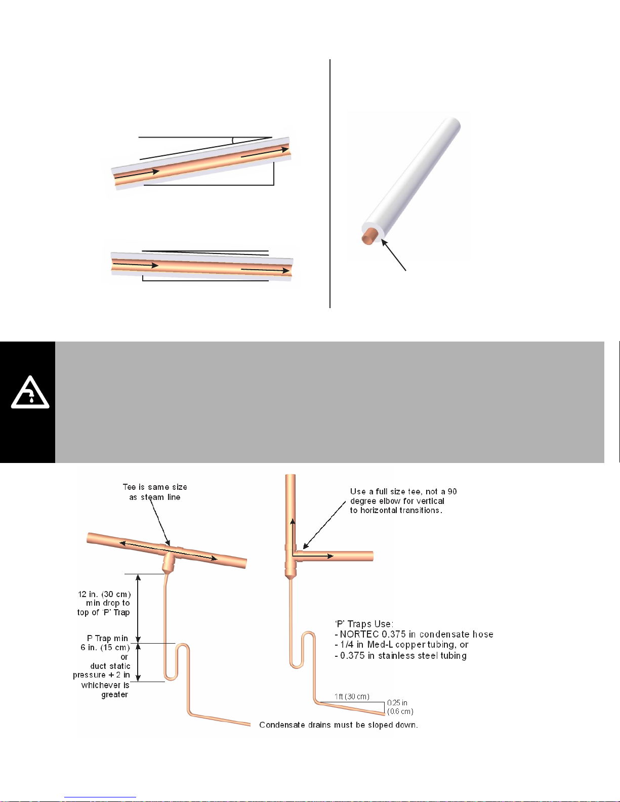
Figure 10: Condensate Traps
17 | Installation
Page 21
Steam Line Rules
The following 10 points provide rules for installing steam lines connecting the NH
humidifier to ASD, BSD, CSD, SAMe and remote blower packs. In addition to these rules
never use unapproved material for steam lines.
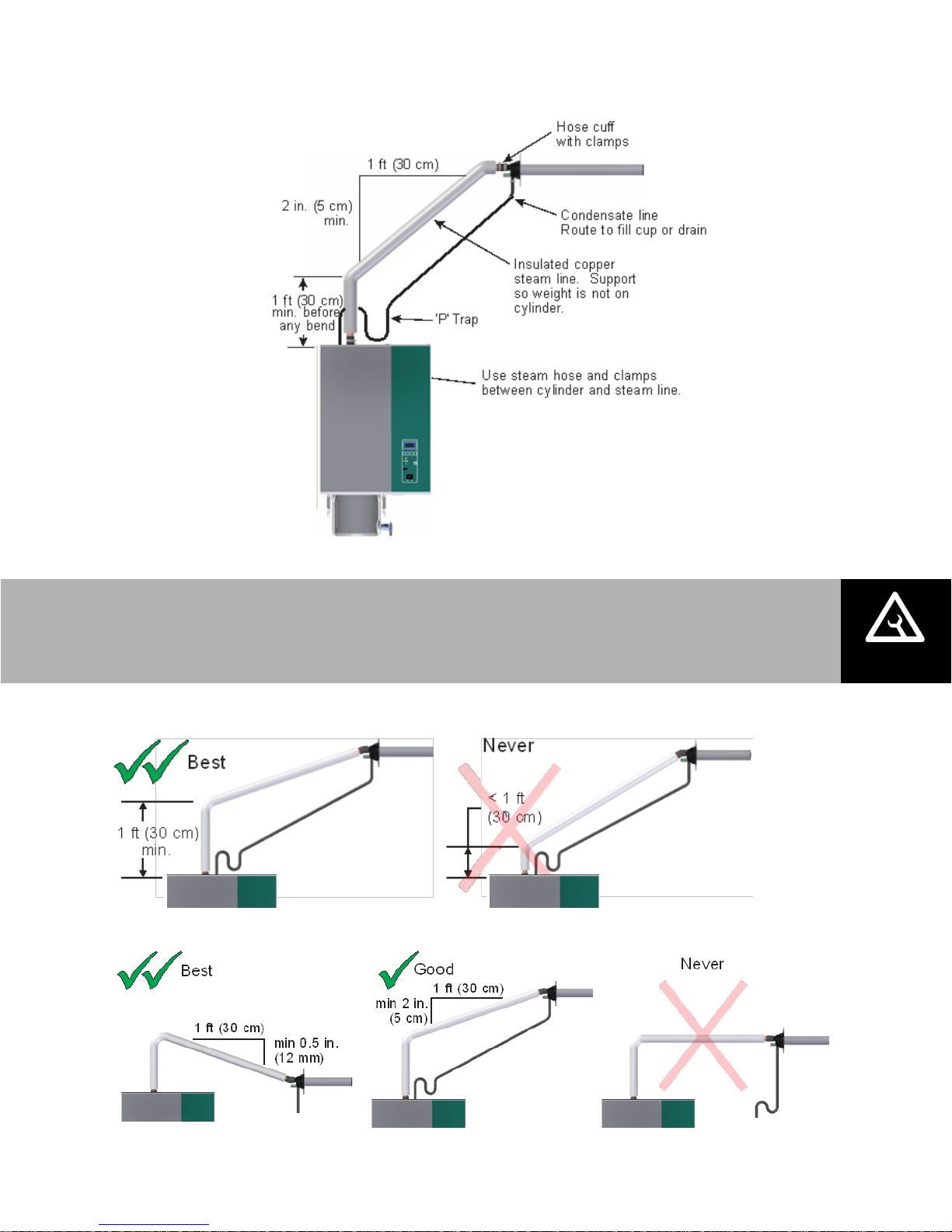
Figure 11: Typical Steam Line Installation
1. Allow a minimum of 12” (30 cm) before first bend in steam line.
2. Slope the steam lines.
Installation | 18
Page 22

3. Use steam hose only for short distances.
4. For steam hose, maintain minimum 12” (30 cm) bend radius.
5. Install traps on condensate lines at least 12” (30 cm) below connection.
6. Only combine steam lines at steam distributor with Nortec adapter.
7. Install condensate traps at low points and horizontal to vertical transitions.
19 | Installation
Page 23

After installation, always
Purge steam lines to remove any contaminants and installation materials.
Ensure all condensate lines/traps flow freely.
8. Increase diameter either on down slope or install condensate trap.
9. Install condensate traps if steam line > 15 feet (4.5 m).
10. In addition, never:
Installation | 20
Page 24

Caution: Wiring to be performed by a licensed Electrician.
To humidifier high
voltage terminal strip
Electrical
Figure 12: Primary Power Connection
21 | Installation
Page 25

Caution: Failure to wire the humidifier in accordance with the wiring instructions
could cause permanent damage. Such errors will void the warranty.
External Controls
Control Wiring
The following information is relevant to all controls, factory supplied or otherwise. For wiring use
a minimum of 18 AWG and keep as short as possible. The NHRS humidifier can be operated
with a modulating input or as On/Off.
Control Location
Duct Humidification
1 Air Proving Switch
Locate so that it can sense air flow, or lack thereof.
2 Duct High Limit
NHRS operates with On/Off control.
Locate at least 10 feet (3.0 m) from steam distributor, or far enough that steam is
fully absorbed under normal conditions.
3 Humidity Control
NHRS can be modulating, On/Off, or a humidity sensor.
Can be located either in return air duct (preferred) or in room being humidified.
Mount in area representative of room humidity (draft, doorways, sunlight, or
overhang such as shelf can affect reading). Avoid placing near discharge diffuser of
humidified air.
4 Outdoor Temperature Sensor
Mount in area representing outdoor air temperature (makeup air duct, outside).
Figure 13: Control Location (Duct Humidification)
Installation | 22
Page 26

1
Humidity
Control
(in location
representative
of the space)
1
Humidity
Control
(in location
representative
of the space)
1
Humidity
Control
(in location
representative
of the space)
Note: Regardless of selecting on/off or modulating control method, Nortec humidifiers must have a
closed circuit across its security loop control terminal to operate. Nortec highly recommends the use
of a high limit humidistat and an air proving switch in series for this function.
Space Humidification
Figure 14: Control Location (Space Humidification)
1 Humidity Control
NHRS can be modulating, On/Off, or a humidity transducer.
Locate in room being humidified but not in discharge zone of blower pack(s).
Mount on indoor wall in area representative of room humidity (draft, doorways,
sunlight, or overhang such as shelf can affect reading).
2 High Limit Humidistat (not shown)
Install a high limit On/Off humidistat in area representative of room humidity.
3 Outdoor Temperature Sensor (not shown)
Mount outside in area representing outdoor air temperature.
23 | Installation
Page 27

On/Off Control Wiring
Figure 15: On/Off Controls
Figure 16: Digital On/Off Humidistat
Installation | 24
Page 28

Figure 17: Duct Sensor Wiring
25 | Installation
Page 29

Modulating Control Wiring
Figure 18: Modulating Controls
Figure 19: Digital Modulating Humidistats
Installation | 26
Page 30

Figure 20: Digital Wall Humidistat - Remote Wall Sensor
27 | Installation
Page 31

Transducer Control Wiring
Figure 21: Transducers
Figure 22: Digital Transducers
Installation | 28
Page 32

Optional Outdoor Temperature Setback Sensor
Figure 23: Outdoor Temperature Setback
Each digital controller is equipped with an integrated reset function that can reduce the
setpoint during cold weather operation. This will prevent condensation on windows and
building structures. The above graph illustrates how the setpoint reset feature operates.
This feature is enabled by removing the jumper from terminals 8 and 1 on the humidistat
and wiring the outdoor temperature sensor to these terminals.
When the outdoor temperature setback feature is in effect, the humidistat will normally
display the calculated setpoint limit based on the outdoor air temperature. A snowflake will
also be displayed to indicate cold weather operation. When any key on the controller is
pressed, the LCD screen will display the customer specified setpoint for a short duration.
Figure 24: Outdoor Temperature Setback wiring
29 | Installation
Page 33

Remote Fault Option Wiring
The NHRS remote fault option (P/N 1508069) includes four relays that can provide remote
status indication. The relays are mounted to a remote fault board which is located as shown in
Figure 26. The PCB with the relays includes markings which indicate the function of each
terminal on the board. The relays indicate the following status:
1 Unit On – The normally open relay is closed when the humidifier has power and the On/Off
switch is set to on.
2 Steam – The normally open relay is closed when the control board detects that the cylinder
is drawing current and steam is being produced.
3 Service – The relay can be wired to open (NC) or close (NO) when a warning is displayed on
the humidifier display and the yellow service LED is illuminated.
4 Error – The relay can be wired to open (NC) or close (NO) when a fault is detected by the
humidifier controls.
Figure 25: Location of Remote Fault board
Installation | 30
Page 34

Note:
For installation of options and accessories follow the instructions that are provided with them.
Figure 26: Remote Mounted Blower Pack.
Options and Accessories
Blower Pack
Optional blower pack (part number 2572615) can be used to distribute steam to localized
areas, or in areas that do not have built-in air distribution systems. Blower packs are available
in remote configuration, are piped in the field, and are wired to the humidifier RMBP power
source (or a separate power source if the installation requires).
For detailed installation information, refer to the Blower Pack installation and operation manual
(document 2572641). Refer to Table 4 and Table 5 on Page 11 for clearance information.
31 | Installation
Page 35

Keep Warm (Outdoor Standard)
Menu configuration setup can be done at factory, which allows the water temperature in the
tank to be maintained at 160ºF (70ºC) for quick response of the unit to a call for humidity. This
aids in minimizing health concerns associated with standing water.
Part number 1504561.
Nortec Online/LINKS2
Nortec OnLine enables a humidifier to communicate and be monitored through the Internet.
Several configurations are available: Dynamic Host Configuration Protocol (DHCP), Dial-up,
General Packet Radio Service (GPRS), Slave, and Static IP. Consult factory for details.
Nortec LINKS provides monitoring and control allowing humidifier(s) to communicate to a
Building Management System (BMS). The controller is factory installed and is located internally
to the humidifier. Several communication protocols are available: BACnet MSTP, BACnet IP,
Johnson N2, and LonWorks. Consult factory for details.
Nortec LINKS2 is a package that includes both items above: a particular communication
protocol as well as Nortec OnLine.
Remote Relay Board
An optional remote fault kit is available that can provide remote indication of humidifier status.
The relays will activate upon the following humidifier conditions: steam production, unit fault,
maintenance/service, and unit power. The kit can be factory or field installed and can interface
with a BMS. See Page 30 for wiring and installation.
Part number 1508069.
Scale Management System
The Scale Management System provides a separate reservoir underneath the steam tank for
scale collection. The addition of this option reduces maintenance time significantly. Minerals
removed from the water during steam production will collect in the scale reservoir rather than in
the tank. When minor maintenance is needed, the scale reservoir is easily removed and
emptied. Without this option, the NHRS requires more effort during minor maintenance:
cleaning of the steam tank and heating elements. More humidifier downtime is required for this
maintenance. With the Scale Management System, minor maintenance simply requires the
scale reservoir to be emptied, which can be done in a matter of minutes.
Part number 2533179 (two must be ordered for units with two tanks, NHRS 135 & NHRS 180).
Solid State Relays
Solid State Relay Control (SSR Control) allow for rapid response upon a call for humidity by
replacing the standard contactors with a higher-performing component. The operating window
for the standard contactor is 2 minutes, but the SSRs will cycles in approximately 2 seconds.
This allow for quick response and tight control of the humidity. This option is essential where a
tight humidity tolerance is required.
Part number will vary according to the capacity and voltage of the unit.
Installation | 32
Page 36

Start Up
34 Installation Check
35 NHRS User Interface
35 Auxiliary Drain Switch
35 Door Interlock Switch
36 Start Up Procedure
36 Initial Start-Up Procedure
38 Information Screens
45 How the Humidifier Works
45 Start Up
45 Automated Operation
46 System Drains
47 Selecting an RH Setpoint
33 | Start Up
Page 37

Installation Check
Before turning on power to the NHRS, inspect the installation to ensure that it was carried out
correctly. Refer to figure below, the NHRS Pre-Start Up Checklist, and the preceding chapter on
installation.
Figure 27: Installation Check
Start Up | 34
Page 38

Door Interlock Switch
and
Auxiliary Drain Switch
NHRS User Interface
Figure 28: NHRS User Interface
Auxiliary Drain Switch
In addition to software controlled draining of the tank , the NHRS has a manual drain switch
which can be used to drain the tank even if software is not functioning. To drain the tank,
put the switch into the drain position. For normal operation the switch should be in the off
position. If the unit has multiple tanks, the switch will have both “Tank A” and “Tank B” settings.
This allows single-tank draining.
Door Interlock Switch
The door interlock switch cuts power to the contactor when the door is removed. It is an
additional safety device intended to prevent the possibility of service technicians coming into
contact with live electrical wiring while working on the humidifier. Pull the switch out with door
off to override.
Figure 29: Door Interlock Switch and Auxiliary Drain Switch
35 | Start Up
Page 39

Warning: Damaged units or improperly installed units must not be operated.
Damaged or improperly installed units may present a danger to persons and property.
Start Up Procedure
1. Examine the humidifier and installation for damage and/or improper installation.
2. Ensure that the doors are in place and secured with retaining screws.
NOTE: if the optional Scale Management System is installed, make sure the valve on the
scale reservoir is closed.
3. Open the supply water shut off valve.
4. Turn on the mains power using the installed disconnect.
5. Press the On/Off switch on the front of the humidifier to turn the humidifier on.
The NHRS humidifier will now carry out a system test. The display below appears and the three
LEDs light for approximately three seconds.
If a fault is detected during the system test, a corresponding fault message is triggered.
If the system test is successful, the steam tank fills up and a float test is carried out
(function check on the level unit). The display below appears.
If a fault is detected during the float test, a corresponding fault message is triggered.
When both tests are successful, the NHRS will enter normal operating mode. The display
below appears and the green LED lights.
Initial Start-Up Procedure
The following procedure should be carried out only on the first occasion that the unit is
operated:
1. Check the function of the humidifier:
a. Switch on the humidification by raising the set humidity value on the humidity
controller / humidistat / NHRS Display.
b. Switch off the humidification by lowering the set humidity value on the humidity
controller / humidistat / NHRS Display.
Start Up | 36
Page 40

LED
Action
Meaning
Green
Constant
Unit Producing Steam
Yellow
Flashing
Major or Minor Service Due.
Red
Flashing
The Unit is trying to self-correct a problem.
Red
Constant
Insoluble Problem
NOTE: Relevant data will be displayed on the NHRS LCD display during normal operation and
when in fault
Relay
Description
Notes
K1
Steam
(N/O) Normally open
K2
Error
(N/O) Normally open Or (N/C) Normally closed
K3
Service
(N/O) Normally open Or (N/C) Normally closed
K4
Unit On
(N/O) Normally open
c. Check for correct functioning of the monitoring equipment (external safety
network).
d. Set the desired humidity value on the humidity controller / humidistat.
e. Make sure no leaks are present.
The heating current switches on as soon as the humidity controller / humidistat
demands humidity. The yellow LED lights and steam is produced after a short delay
(approximately 5 minutes).
2. The operating status is displayed in the LED on the unit as follows:
Table 8: NHRS Operational Status LEDs
3. If the humidifier is equipped with the optional Remote Fault Indication, the operating
status will be shown as follows:
Table 9: Remote Fault Indication
37 | Start Up
Page 41

Information Screens
The NHRS has a “display menu” from which various operating parameters can be viewed. It is
not possible to change the values on the display level.
1. Display level operation
a. Call up the display level with <↑> or <↓>.
b. <↓> next operating parameter.
c. <↑> previous operating parameter.
d. Exit the display level with <Menu>.
2. Description of the operating parameters on the display level.
NOTE: The following describes the individual operating parameters that can be selected
using the keys <↑> and <↓>, after the display level has been called up.
a. Steam Production
1. Current, actual, and nominal value of steam production are displayed in
percentage of total output.
2. Nominal value: unit capacity x input signal value.
3. Actual value: max unit capacity x input signal value x capacity limitation
If the internal controller is activated, only the actual value is shown. Under the following
conditions the actual value may differ from the nominal value: upon activation of the
heating power, if capacity limitation is active during the filling cycle of the steam cylinder.
b. Analog Input
1. Current value of the signal applied to the analog input in [%] of its max value.
If the internal controller is active, the displayed value corresponds to the current air
humidity (% RH).
c. Internal Controller
1. Internal controller activated (“on”)/deactivated (“off”).
2. Activated with transducer signal.
3. De-activated with demand signal.
Start Up | 38
Page 42

S2 Position
Interval Minor
Maintenance
Interval Major
Maintenance
0
200 hours
600 hours
1
300
600
2
300
900
3
450
900
4
400
1200
5
600
1200
6
500
1500
7
750
1500
8
3000
3000
9
6000
6000
0 200 hours 600 hours
1 300 hours 600 hours
2 300 hours 900 hours
3 450 hours 900 hours
4 400 hours 1200 hours
5 600 hours 1200 hours
6 500 hours 1500 hours
7 750 hours 1500 hours
8 3000 hours 3000 hours
9 6000 hours 6000 hours
PositionS2Interval Minor
Maintenance
Interval Major
Maintenance
10 0
15 0
20 0
30 0
45 0
6 0
90 0
135 0
180 0
S2 Setting
NHRS
Model
Value Setting
Factory Setting
NHRS Main PCB
Maintenance Interval
Adjustment [S2]
d. Working Hours
1. Total of working hours elapsed since initial commissioning of the humidifier.
e. Time Remaining to minor/major service
1. Time remaining (in hours) before the next minor/major service.
Time to maintenance can be adjusted to suit water conditions.
The stated times are based on 100% steam capacity. If the operation is at a lower
capacity, the time should be extended accordingly. For example, average capacity of
50% would double the time to maintenance. Average capacity of 33% would triple the
time to maintenance. The servicing intervals are set up using the rotary switch “S2” on
the control board.
NOTE: S2 rotary switch is set at factory to “0”.
Table 10: Maintenance intervals with rotary switch S2
39 | Start Up
Figure 30: Maintenance interval adjustment S2
Page 43

S1 Position
Drain Intervals at
100% Steam Capacity
0
0 min
1
720
2
360
3
180
4
120 5 60
6
30 7 20
8
10 9 5
f. Drain Cycle
1. The following indications are provided for the set-flushing interval
Left: Switch setting on rotary switch “S1” (4 in example)
Right: Set flushing interval (120 in example)
The flushing interval is set on switch “S1” on the control board.
Table 11: Drain Cycle intervals with rotary switch "S1"
NOTE: S1 rotary switch is set at factory to “9”.
NOTE: Water quality conditions resulting in component failures are not covered
under Nortec’s standard warranty. The factory settings are based on the
following water conditions when the unit leaves the factory.
Should you have water conditions more aggressive that the stated parameters,
consult the factory for a new drain cycle setting to help improve your scale
management.
Figure 31: Drain Cycle adjustment S1
Start Up | 40
Page 44

Water
Parameters
Potable Water
Treated Water
Conductivity
0-1500 Siemens
0-50 Siemens
Hardness
12 grains per gallon
0 grains per gallon
Silica
12 ppm
0 ppm
pH
6.5-7.5
7
Chlorides
> 50 ppm
> 25 ppm
Table 12: Water quality
Nortec recommend performing a semi-annual water analysis to ensure optimal
performance.
g. Stand-by Heating (also known as “Keep Warm”)
1. Stand-by Heating activated (“on”) or deactivated (“off”).
NOTE: If stand-by heating is active, the water temperature in the steam tank is
constantly kept at approximately 158ºF (70ºC) by the control board.
h. Capacity Limitation
1. To change the Power Limit (Maximum Capacity), complete the following:
• Press both arrow keys simultaneously,
• Enter code “8808”,
• Change to desired value, and
• Press both arrow keys simultaneously.
i. Inlet Valve Correction
1. Set inlet valve correction (cycle ratio) in % of standard setting value to balance
out water pressure variations. Contact factory for more details.
j. Soft Start
1. Soft Start activated (“on”), consult factory. Deactivated (“off”), factory default.
41 | Start Up
Page 45

k. De-mineral Mode
1. De-mineral Mode activated (“on”), consult factory. Deactivated (“off”), factory
default.
l. Serial Interface
1. Serial Interface activated (“on”), consult factory. Deactivated (“off”), factory
default.
m. Full Drain Cycle
1. Full Drain Cycle activated (“on”), consult factory. Deactivated (“off”), factory
default.
n. Flush Cycle
1. Flush Cycle activated (“on”), consult factory. Deactivated (“off”), factory
default.
Start Up | 42
Page 46

S3 Position
Signal
0
No signal selected
1
Spare
2
0-5 VDC
3
0-10 VDC
4
Other
5
1-5 VDC
6
2-10 VDC
7
Other
8
4-20 mA
9
0-20 A
o. Control Signal
1. Range of the active analog signal in Volts or milliamps.
NOTE: The range of the analog signal may be adjusted using the rotary switch
“S3” on the control board.
Table 13: Control signal settings with rotary switch "S3"
Figure 32: Control signal setting S3
43 | Start Up
Page 47

p. Software Version
1. Displays software version for the steam humidifier.
q. Unit Type
Start Up | 44
Page 48

How the Humidifier Works
The NHRS is an isothermal humidifier that produces atmospheric steam at operational
pressures of -3 to +6 in. W.C. System operation is based upon regulating the operation of
Incoloy immersion resistive heating elements with pulse width modulation via contactor(s) or
optional solid state relay(s).
Start Up
1. Upon powering up the NHRS, a brief diagnostic process will be initiated, once this is
completed the humidifier will initiate a level sensing test. To initiate this test, it is
required that the operational water level be at level 1 or less. If the reservoir is above
this level the system will initiate a drain. If the water level is less than level 1, both
1.2 litre per min fill solenoids will be activated in order to recover water level quickly.
Once level 1 water level or greater is achieved, the system will fill with only a single
solenoid in order to increase the accuracy of the level sensing.
2. The level sensing test will perform a timed fill to water level 4 and initiate a drain
process to level 3. If both the fill and drain system successfully operate within the
allotted time requirements, the humidifier will assume automated operation.
Otherwise the system will generate a fault condition and display diagnostic
information.
Automated Operation
1. System operation is initiated by satisfying various control inputs that are specific to
the system configurations. Once the configured control inputs are satisfied, and
water levels are within operational requirements (level 1-4), steam production can
commence.
2. Steam production sequence will vary depending upon hardware configuration. Units
with the optional SSR relay kit should progress to step 2.2. Units with standard
contactors progress to step 2.1.
2.1. CONTACTORS: Once system demand exceeds 10% the contactors will close. The
contactor will pulse width modulate over 120 second cycles. At 11% demand the
contactor will be closed for 10 seconds and will increase the length of operation,
in relation to an increase in system demand in a linear fashion up to 98%
demand. At 98% demand and above the contactor will remain closed for the
maximum 120 seconds. Cylinders with multiple contactors will increment
operating time sequentially amongst all contactors in order to scale output to
demand.
2.2. SSR & CONTACTORS: Once system demand exceeds 4%, the contactors will
activate and pulse the SSR to modulate heat production up to 98% demand. At
98% demand and above the SSRs will remain constantly closed. For cylinders
with multiple solid state relays the system will increment operating time amongst
all SSRs sequentially in order to scale output to demand.
3. Once the contactors close, the fill system initiates pulse fill in order to anticipate
evaporation and maintain the operating water level. Operating pulses will increase as
the water level decreases, and conversely decrease the filling pulses as water level
45 | Start Up
Page 49

increases. This allows the humidifier to continuously evaporate without interruption
and prevents larger influxes of cold water that may otherwise interrupt system
operation by cooling the boiling chamber.
System Drains
1. System operation will continue in this state until the timer controlled flushing
(determined by the S1 dial selector switch on the processor board) is achieved. When
triggered, steam production will continue without interruption and the system will initiate
a drain of one water level.
2. The timer controlled flushing is based upon system operating at 100% capacity.
Operating at a lower system capacity will extend the drain interval by the factor of the
reciprocal of system demand (averaged for the length of the flush timer) to the flush
timer.
3. With very low demand this method can lead to exceedingly long intervals between
system flushes. In order to prevent the drain interval from becoming excessively long, a
function is used to limit maximum wait time before initiating the drain procedure. This
roughly equates to preventing the drain interval from exceeding 10 x the Flush Timer
setting.
4. Once triggered, the system will wait for a minimum water level of three, so as to not
interrupt steam production. If the system drain is triggered by the maximum wait time
the system will fill to level four and then evaporate to level three prior to draining. If the
level requirement is not achieved the filling pulses of the fill valve will be extended in
order to increase the water to levels permissible of initiating the system drain. Once
complete the fill valve operation will resume normal pulse control.
Start Up | 46
Page 50

Note: The job site design may have specified a setpoint chosen specifically for the site.
Refer to site documentation and where possible use setpoints specifically determined
for the site.
Selecting an RH Setpoint
The optimum humidity setpoint depends on the reasons that a conditioned environment is
being humidified. The “ASHRAE Handbook – HVAC Applications” recommends specific design
relative humidities for specific applications. Also see NORTEC publication “When You Need
Humidity” (Form 124A) for more information on humidity settings.
Health and Comfort - The benefit of humidity is most pronounced for health and comfort in the
40-60% range. A humidity setting of 40-50 % is recommended for this purpose to prevent over
humidifying.
Temperature Setback - In cold climates it is often necessary to reduce the humidity level in a
conditioned environment to prevent build-up of condensation on the inside of exterior walls,
windows, and trim. It is highly recommended that the temperature setback function of the
NORTEC digital controls be used under these conditions to prevent damage from condensation.
The digital control with an outdoor temperature sensor installed will automatically setback the
humidity setpoint to correspond with outdoor temperature.
Duct High Limit – The duct high limit is intended to prevent saturation and wetting in duct work
at high load conditions. NORTEC recommends a setting of 85% for the duct high limit. It may
be necessary to reduce this setting if the duct work is very cold or in contact with exterior cold
surfaces.
47 | Start Up
Page 51

Maintenance and Servicing
49 Minor Maintenance
51 Major Maintenance
Maintenance and Servicing | 48
Page 52

WARNING: A qualified service person should perform all maintenance on the
humidifier and any other equipment provided by Nortec that requires maintenance.
NOTE: Instruction and details concerning the maintenance of the Nortec equipment
must be observed and adhered to without fail. Only the maintenance documented
in this manual must be carried out.
WARNING: The NHRS brings water up to boiling temperatures. The steam tank and
plumbing components may be hot. Allow the unit an appropriate amount of time to
cool before performing service.
WARNING: High voltage! Disconnect main power before servicing the unit
Minor Maintenance
The NHRS will indicate “minor maintenance due” with a yellow flashing LED and a
message on the LCD.
1. Visual inspection must be performed before minor and major maintenance.
a. Inspect all water and steam installations for possible leakage or damage.
b. Inspect electrical installation for lose or frayed cables, as well as damaged
components.
c. Inspect the condition of the unit cabinetry for damage.
d. Survey the area surrounding the humidifier – make sure all clearances are met.
2. Maintenance
a. Manually drain the NHRS by pressing the drain button on the display.
b. Turn the unit power to the “off” position.
c. Switch the external electrical disconnect to the “off” position (open).
d. Remove the screw that holds the front door on the cabinetry in place.
e. Remove the Font Panel by sliding the panel upward and away from the unit.
f. Confirm that the high voltage feed to the unit is off, then remove the high voltage
wires that connect to the top of the steam tank.
The heating elements will not be affected if they are connected to different power lines
when re-installed. When re-connecting heating elements, ensure a tight engagement
with a “click” of the connectors.
g. Using a slotted screwdriver, loosen the gear clamps that hold the steam line in
place.
h. Remove the steam line.
49 | Maintenance and Servicing
i. Remove the zip-tie cylinder restraint.
j. Lift the cylinder upward, then out of the front of the unit.
Page 53

CAUTION: Be extremely careful when handling the steam cylinder. If it is
dropped and damaged, it will likely not seal properly and the entire cylinder
will need to be replaced.
Figure 33: Minor maintenance with optional Scale Management System
k. Remove the clamp at the top of the cylinder.
l. Remove the tank lid with the elements attached.
m. Remove all scale from the tank.
n. Inspect the heating elements for damage.
o. Re-install the equipment in reverse order.
p. Turn power and water supplied back on to the unit.
q. Turn on the unit and carry out the steps of the visual inspection once more.
No maintenance re-set is required for Minor Maintenance Interval.
Maintenance and Servicing | 50
Page 54

Maintenance Item
Unit has Scale
Management
System?
Minor
Maintenance
Interval
Major
Maintenance
Interval
Remove scale tank and empty
Yes
Required
Required
No
N/A
N/A
Remove steam tank - clean inside,
as well as heating elements
Yes
Optional
Required
No
Required
Required
WARNING: A qualified service person should perform all maintenance on
the humidifier and any other equipment provided by Nortec that requires
maintenance.
NOTE: Instruction and details concerning the maintenance of the Nortec
equipment must be observed and adhered to without fail. Only the
maintenance documented in this manual must be carried out.
Major Maintenance
Major maintenance items include all those for the minor maintenance service, with the
exception that the steam tank must be cleaned at this point. The differences in maintenance
requirements are shown below.
Table 14: Minor and major maintenance
Resetting Maintenance Indication (Major Maintenance Only)
1. Restore primary voltage to the unit.
2. With the unit in the “off” position, press and hold the drain activation switch.
3. Continue to hold the drain activation switch and turn the main power switch to the “on”
position.
4. Allow the unit to undergo initial startup diagnostics. When the diagnostics are complete,
release the drain activation switch. The unit maintenance should be cleared at this
point.
51 | Maintenance and Servicing
Page 55

Troubleshooting
53 General Troubleshooting
55 Wiring Diagrams
57 Start Up Checklists
57 NHRS Electric Steam Humidifier – Mandatory Pre-Start-Up Checklist (p1 of 3)
58 NHRS Electric Steam Humidifier – Mandatory Pre-Start-Up Checklist (p2 of 3)
59 NHRS Electric Steam Humidifier – Mandatory Pre-Start-Up Checklist (p3 of 3)
60 Maintenance Checklists
Troubleshooting | 52
Page 56

Malfunction / Indication
Cause
Remedy
Min. Filling time too short
Error code: 1A/1B
Alarm1A
fillingtime
Error1B
Fillingtime
Steam cylinder heavily calcified.
Level in steam cylinder and level
in the float chamber do not match.
Carry out major servicing.
Level sensing unit faulty.
Test the level sensing unit is
operational by activating a drain
and noting if the LED sequence
changes, indicating a drain.
Internal safety chain
interrupted Error code: 2A/2B
Alarm2A
Safetychainint Error2
safetychainint
Connection to over-temperature
switch on steam cylinder is
broken or over-temperature
switch faulty.
Check connections or replace
over-temperature switch.
Steam cylinder overheating, over-
temperature switch has
responded.
Inspect steam cylinder, clean if
necessary. Replace over-
temperature switch.
Flat-band cable between control
and power board interrupted or
not connected.
Inspect connections, connect or
replace flat-band cable.
Door switch is disengaged.
Door switch safety connection is
closed by either pushing the
switch (such as when the door is
installed), or by pulling the switch.
Max. Filling time exceeded
(alarm message only) Error
code: 3A/3B
Alarm3A
Water supply
Water feed blocked (main water
tap closed, filter valve closed or
blocked). Water pressure too low.
Inlet valve does not open, filter
sieve in Inlet valve blocked or
inlet valve faulty. Feed hoses into
the steam humidifier not
connected or kinked. Level unit
not connected. Float in the level
unit sticking or level unit faulty.
Check water feed, open main
water tap, open or clean filter
valve. Raise water pressure
(range 1-10 bar). Inspect
electrical connections and fuse F2
on supply module. Clean filter
sieve or replace Inlet valve.
Inspect hoses into unit and
connect if necessary. Replace
faulty hoses. Connect level unit.
Clean or replace level unit.
General Troubleshooting
Most operational malfunctions are not caused by faulty equipment but rather by improper
installation, or disregard for planning guidelines. Therefore, a complete fault diagnosis always
involves a thorough examination of the entire system. Often, the steam hose connection has not
been properly executed or the fault lies with the humidity control system. The following table
gives a list of possible malfunctions, the appropriate alarm or error message, details of their
cause, and notes on how to deal with each problem.
Table 15: Troubleshooting errors and warnings
53 | Troubleshooting
Page 57

Malfunction / Indication
Cause
Remedy
Max. Boil down rate too long
Error code: 4A/4B
Error4B
SteamtimeAlarm
4Asteamtime
Individual heating elements faulty.
Replace faulty heating elements.
Main voltage too low or failure of
a phase (L1, L2 or L3).
Replace fuses on power board.
Check main voltage and
connections.
Steam line too long or not
insulated.
Maintain maximum line lengths
(max. 15’). Insulate steam lines.
Max. Drain time exceeded
Error code: 5A/5B
Alarm5Adrain
Error5Bdrain
Drain pump not connected or
faulty.
Connect or replace drain pump.
Outlet line from unit kinked or
blocked.
Inspect outlet line from unit,
replace if necessary.
Water outlet blocked (external
outlet line or siphon blocked.
Clean water outlet line and
siphon.
Hose to level unit blocked.
Clean or replace hose.
Invalid level
Error code: 6A/6B
Alarm6A
Levelindicat
Error6B
levelindicat
Level unit faulty.
Replace level unit.
Magnetic field in vicinity of level
unit.
Eliminate magnetic field.
Steam pressure (error only)
Error code: 7A/7B
Alarm7A
communication
Steam hose blocked or restricted
(water trap).
Inspect steam hose, clean if
necessary and install correctly.
Pressure balance adapter into
steam connection fitting blocked.
Remove adapter and clean
opening with a needle.
Duct pressure too high
(>1500 Pa).
Inspect ventilation settings.
External safety chain
interrupted Error code: none
SafetychainexternalA
Mainsfailure B
Ventilator lock open.
Switch on ventilator/ventilation
system.
Automatic flow control has
responded.
Inspect ventilator/filter of
ventilation system.
Safeties are open.
Servicing, inspect system if
necessary.
Main failure on Unit B.
Inspect voltage supply to Unit B.
Table 14: Troubleshooting errors and warnings (continued)
Troubleshooting | 54
Page 58

Figure 34: Wiring Diagram (NHRS 010 to 090)
Wiring Diagrams
55 | Troubleshooting
Page 59

Figure 35: Wiring Diagram (NHRS 135 to 180)
Troubleshooting | 56
Page 60

WATER QUALITY:
Well water
City water
Softened water
Conductivity: _______mhmos
Hardness: _____gr.
Silica____ppm
HUMIDIFIER MOUNTING:
Clearances around the unit:
Acceptable
Obstruction
Front (door opens freely?)
3ft min
__________________
Top (steam lines)
1ft min
____________________
Bottom (fill, drain, controls)
1ft min
____________________
Right (main pwr)
3ft min
____________________
Left (main pwr)
2” min
____________________
Start Up Checklists
NHRS Electric Steam Humidifier – Mandatory Pre-Start-Up Checklist (p1 of 3)
Unit Serial #: ____________ # of humidifiers: ____________ Tag:_____________
Unit type: NHRS Voltage: _____V/___ph Steam output: ____lbs./hr
Customer/Job:_______________
Address: ____________________________________________________________________
Inspected by: ____________ Date of inspection: ___/___/___
Ensure the scale tank bracket is locked in place
STEAM LINES: CONDENSATE LINES:
Slope up 2” per 12” Slopped back to drain
Slope down ½” per 12” Trapped 2” more than static duct pressure
Traps Size _______
Insulated Length/Size ____________
90º elbows qty: ____ 45 deg. Elbows qty: ____
Can condensate be trapped anywhere in the steam line? Yes no
WATER LINES:
½” at max 4ft from the unit -3/8” connection at fill
Water pressure: 30-80psig
57 | Troubleshooting
Page 61

NHRS Electric Steam Humidifier – Mandatory Pre-Start-Up Checklist (p2 of 3)
DRAIN LINES:
Air gap located within 3ft of the unit Slopped to drain Size:______________
WIRING:
No loose wires around the unit or on the PC board? Yes no
CONTROLS:
Installed Location/Wiring/Setting
High limit: _________________
Air proving: _________________
Mod controller: _________________
Other: _________________
POWER:
Voltage, amperage rating and fuse corresponds to Spec Label
Disconnect switch located close to humidifier
Field contact:___________________________ Signature:_______________________________
Troubleshooting | 58
Page 62

NHRS Electric Steam Humidifier – Mandatory Pre-Start-Up Checklist (p3 of 3)
Unit Serial #: ____________ # of humidifiers: ____________ Tag:_____________
Unit type: NHRS Voltage: _____V/___ph Steam output: ____lbs./hr
Customer/Job:___________ Address: ___________________________________________
Start-up by: _____________ Date of Start-up: ___/___/___
PRELIMINARY:
Pre-start-up checklist completed? Yes No
If no, return to Pre-Start-up Checklist before going on with start-up procedure.
START-UP PROCEDURE:
The prerequisites for getting power and water into the steam cylinder is as follows:
1. Check that main breaker is on and power is at the unit.
2. Check that main water shut-off valve is open.
3. on/off switch must be switched on.
4. Control circuit 1 - 2 must be made.
5. Modulation humidistat, if present, must be calling.
6. Door interlock switch must be made (interlock switch can be pulled out to operate unit).
NOTE:
The unit will undergo a System Test to ensure integrity of all the components. If the test is successful,
the unit will fill and the float test will be carried out. If everything ok, the green light will come on and
the display will show NHRS Ready.
OPERATIONAL CHECK:
1. Switch on the humidification by raising the humidity set point on the humidistat/controller.
2. Switch off the humidification by lowering the humidity set point on the humidistat/controller.
3. Check for correct functioning of the external monitoring safeties such as air proving and high
limit.
4. When check complete: Set the desired humidity level.
REMARKS:
____________________________________________________________________________________
____________________________________________________________________________________
____________________________________________________________________________________
____________________________________________________________________________________
____________________________________________________________________________________
59 | Troubleshooting
Page 63

Maintenance Checklists
Unit Serial #: ____________ # of humidifiers: ____________ Tag:_____________
Unit type: NHRS Voltage: _____V/___ph Steam output: ____lbs./hr
Customer/Job:___________ Address: ___________________________________________
Maintenance by: _____________ Date of Maintenance: ___/___/___
TYPE OF MAINTENANCE*:
Minor maintenance, 2-3 times per year:
Inspect all water and steam installations for possible leakage or damage.
Inspect electrical installation for loose or frayed cables, as well as damaged components.
Inspect the condition of the unit cabinetry for damage.
Survey the area surrounding the humidifier – make sure all clearances are met.
If equipped with scale tank: remove scale tank and empty
If not equipped with scale tank: remove boiling tank, clean inside as well as heating
elements.
Major maintenance, at least once per year:
Inspect all water and steam installations for possible leakage or damage.
Inspect electrical installation for loose or frayed cables, as well as damaged components.
Inspect the condition of the unit cabinetry for damage.
Survey the area surrounding the humidifier – make sure all clearances are met.
Remove scale tank and empty
Remove boiling tank, clean inside as well as heating elements.
Reset maintenance indication
Seasonal maintenance, at the conclusion of the humidification season**:
All items from “Major maintenance” section.
Inspect boiling tank for pitting and/or corrosion due to harsh supply water.
Inspect drain pump to ensure there is no blockage.
* Note that the duration of the maintenance intervals can be set by the user. See Table 10 on
page 39 for details. For additional details on maintenance, see section Maintenance and
Servicing on page 48.
** The “humidification season” is typically the winter months, where cold outdoor air requires
heat and humidification before being delivered into a conditioned environment. There are
geographical areas where the humidification season is all year long i.e. locations where summer
months are very dry.
Troubleshooting | 60
Page 64

Spare Parts
62 NHRS Plumbing Parts
64 NHRS Electrical Parts
Part Ordering
The following illustrations and tables list the most commonly used NHRS parts.
First locate the part you require in the illustration corresponding to your NHRS unit.
Find the item number in the first column of the table adjacent to the illustration.
Read across the table to the column which corresponds to the number of phases,
voltage, and capacity of your unit.
To order parts, or help in identifying the part you need, contact your local Nortec
agent.
61 | Spare Parts
Page 65

NHRS Plumbing Parts
Figure 36: Exploded view, NHRS plumbing parts
Spare Parts| 62
Page 66

Table 16: Exploded view, NHRS plumbing parts
575
460
575
460
575
460
575
460
230
208
575
460
230
208
575
460
230
208
575
460
230
208
575
460
230
208
575
460
230
208
575
460
230
010/1 015/1 020/1 030/1 180/3135/3090/3065/3045/3030/3
208
1111111111111111111111111111112222
1111111111111111111111111111112222
1111111111111111111111111111112222
1111111111111111111111111111112222
1111111111111111111111111111112222
1111111111111111111111111111112222
1111111111111111111111111111112222
1111111111111111111111111111112222
1111111111111111111111111111112222
1111111111111111111111111111112222
1111111111111111111111111111112222
1111111111111111111111111111112222
1111111111111111111111111111112222
1111111111111111111111111111112222
1111111111111111111111111111112222
1111111111111111111111111111112222
123612
123612
1236
1236
123612
123612
123
123
1111111111111111111111111111112222
1111111111111111111111111111112222
1111111111111111111111111111112222
1111111111111111111111111111112222
1111111111111111111111111111112222
1111111111111111111111111111112222
1111111111111111111111111111112222
1111111111111111111111111111112222
1111111111111111111111111111112222
63 | Spare Parts
Spare Parts List NHRS Plumbing Section
Voltage
Capacity
Fill Cup Assembly
Drain Canal Assembly
Fill Valve Assembly
Drain Pump Assembly
Drain Water Cooling Valve Assembly
O-ring kit, units with scale tank (optional)
O-ring kit, units without scale tank
Tank Base
Tank Base for Scale Management Option
Tank
Plastick Liner with Funnel
Stainless Steel Liner
Steam Outlet
Steam Outlet Hose
Tank Clamp
1116483
1116482
Part Number Description
1 1508019
2 2526944
3 2573527
4 1502644
5 2541095
6 2573903
7 2573904
8
9 1113772
10 1117634
11 1119101
12 1509465
13 2557455
14 1109384
SP Heating Element, 11.25 lbs/hr 208V Assembly
SP Heating Element, 11.25 lbs/hr 240V Assembly
SP Heating Element, 11.25 lbs/hr 480V Assembly
SP Heating Element, 11.25 lbs/hr 600V Assembly
SP Heating Element, 15 lbs/hr 208V Assembly
SP Heating Element, 15 lbs/hr 240V Assembly
SP Heating Element, 15 lbs/hr 480V Assembly
SP Heating Element, 15 lbs/hr 600V Assembly
Tank Lid
Tank Gasket
Temperature Switch
Scale Tank Bracket (Scale Management Option)
Scale Tank (Scale Management Option)
Water Leveling Sensor
Float Chamber Mounting Bracket
Float Chamber
Fitting, Nylon Male, 1/2 NPT, Female GH
2578492
2578493
2578494
2578495
2578496
2578497
2578498
2578499
15
16 1119102
17 1110091
18 1502684
19 1505914
20 2573902
21 2511137
22 1113777
23 1114768
24 1509787
1113796 Drain Disk, NHRS 1111111111111111111111111111112222
not shown
Page 67

NHRS Electrical Parts
Figure 37: Exploded view, NHRS electrical parts
Spare Parts| 64
Page 68

Table 17: Exploded view, NHRS electrical parts
575
460
575
460
575
460
575
460
230
208
575
460
230
208
575
015/1 020/1 030/1 180/3135/3090/3065/3045/3030/3
010/1
460
230
208
575
460
230
208
575
460
230
208
575
460
230
208
575
460
230
208
1111111111111111111111111111111111
1111111111111111111111111111111111
11 11 1 2
111111111111111111
11 1
1 11 221 12 2
1112
1111111122
1111111122
1111111
1111111111111111
11111111 11 11
1111111111111111111111111111111111
1111111
1111111111111111111111111111111111
11 22
1111111111111111111111111111112222
111111111111 112222 222222224444
1111111111111111111111111111111111
1111111111111111111111111111111111
1111111111111111111111111111112222
65 | Spare Parts
Voltage
Spare Parts List NHRS Electrical Section
Capacity
Main PCB NHRS
Ground Clamp
Terminal Block 2 pole 95 amp
Terminal Block 3 pole 95 amp
Contactor 30 amp 1 ph
Contactor 30 amp 3 ph
Contactor 40 amp 3ph
Contactor 50 amp resistive 3 pole
2574153
2574154
2574148
Contactor 62 amp 3 ph
LCD Display
2574149
2574150
2574151
2574152
Transformer 24VAC 150VA, Primary 208
2574166
On/Off rocker switch
Transformer 24VAC 150VA, Primary 240
Transformer 24VAC 150VA, Primary 480
Transformer 24VAC 150VA, Primary 600
2574167
2574168
2574169
Part Number Description
1 1118676
2 1323020
3
4
5 1114890
6
7 2522489
Support PCB
Solid State Relay + Heat Sink 45 amp (max qty shown)
Solid State Relay + Heat Sink 75 amp (max qty shown)
Interlocking door switch
Remote fault PCB (optional)
8 1323091
9 1508069
PCB Breakout Board
2541096
2541097
10 1115000
12 1503141
11
Page 69

Warranty
Nortec Humidity Inc. and/or Nortec Humidity Ltd. (hereinafter collectively referred to as THE
COMPANY), warrant for a period of two years after installation or 30 months from
manufacturer’s ship date, whichever date is earlier, that THE COMPANY’s manufactured and
assembled products, not otherwise expressly warranted (with the exception of the cylinder), are
free from defects in material and workmanship. No warranty is made against corrosion,
deterioration, or suitability of substituted materials used as a result of compliance with
government regulations.
THE COMPANY’s obligations and liabilities under this warranty are limited to furnishing
replacement parts to the customer, F.O.B. THE COMPANY’s factory, providing the defective
part(s) is returned freight prepaid by the customer. Parts used for repairs are warranted for the
balance of the term of the warranty on the original humidifier or 90 days, whichever is longer.
The warranties set forth herein are in lieu of all other warranties expressed or implied by law. No
liability whatsoever shall be attached to THE COMPANY until said products have been paid for in
full and then said liability shall be limited to the original purchase price for the product. Any
further warranty must be in writing, signed by an officer of THE COMPANY.
THE COMPANY’s limited warranty on accessories, not of the companies manufacture, such as
controls, humidistats, pumps, etc. is limited to the warranty of the original equipment
manufacturer from date of original shipment of humidifier.
THE COMPANY makes no warranty and assumes no liability unless the equipment is installed in
strict accordance with a copy of the catalog and installation manual in effect at the date of
purchase and by a contractor approved by THE COMPANY to install such equipment.
THE COMPANY makes no warranty and assumes no liability whatsoever for consequential
damage or damage resulting directly from misapplication, incorrect sizing or lack of proper
maintenance of the equipment.
THE COMPANY makes no warranty and assumes no liability whatsoever for damage resulting
from freezing of the humidifier, supply lines, drain lines, or steam distribution systems.
THE COMPANY retains the right to change the design, specification and performance criteria of
its products without notice or obligation.
Warranty | 66
Page 70

U.S.A.
826 Proctor Avenue
Ogdensburg, NY 13669
CANADA
2740 Fenton Road
Ottawa, Ontario K1T 3T7
TEL: 1.866.NORTEC1
FAX: 613.822.7964
EMAIL: nortec@humidity.com
WEBSITE: www.humidity.com
 Loading...