

Page 1
Important: Read and save these instructions. This guide to be left with equipment.
2570435 D | 25 JUN 2014
NH-EL
Series
Installation and
Operation Manual
Includes installation, operation
maintenance and troubleshooting
information for your NH-EL Electric
Steam humidifier
Page 2

INSTALLATION DATE (MM/DD/YYYY)
MODEL #
SERIAL #
CYLINDER #
Thank you for choosing Nortec.
Proprietary Notice
This document and the information disclosed herein are proprietary data of Nortec Humidity Ltd. Neither this
document nor the information contained herein shall be reproduced, used, or disclosed to others without the
written authorization of Nortec Humidity Ltd., except to the extent required for installation or maintenance of
recipient’s equipment.
Liability Notice
Nortec does not accept any liability for installations of humidity equipment installed by unqualified personnel or
the use of parts/components/equipment that are not authorized or approved by Nortec.
Copyright Notice
Copyright 2014, Nortec Humidity Ltd. All rights reserved.
Page 3

Contents
1 Introduction
2 Receiving and Unpacking
3 Humidifier Components
5 NH-EL Models
6 Options and Accessories
9 Installation
10 Typical Humidifier Installation
11 Location
13 Mounting with Keyholes
14 Plumbing
15 Steam Distributor
16 Steam Lines and Condensate
Returns
21 Electrical
48 Operation
49 LED Status Lights
51 How the Humidifier Works
54 NH-EL Humidifier Configuration
62 Maintenance and
Servicing
63 Required Maintenance
68 Extended Shutdown
69 NH-EL Maintenance Checklist
70 Troubleshooting
72 General Troubleshooting
75 NH-EL Warnings and Faults
81 NH-EL Wiring Diagram (Cylinder A)
82 NH-EL Wiring Diagram (Cylinder B)
22 External Controls
36 Options and Accessories
38 Start Up
39 Installation Check
40 NH-EL User Interface
41 Start Up Procedure
42 Information Screens
43 Nortec Digital Controls
46 NH-EL Pre-Start Up Checklist
47 NH-EL Start Up Checklist
83 Spare Parts
95 Warranty
Page 4
CAUTION: Servicing
Humidity Ltd.
CAUTION: Electrical
CAUTION: Plumbing
All plumbing work should be done according to local plumbing code.
CAUTION: Installation
proving switch in series for this function.
Introduction
Disconnect main power before any servicing.
The plumbing and electrical compartments contain high voltage components and
wiring. Access should be limited to authorized personnel only.
During and following operation of the humidifier, the steam and components in
contact with the steam such as the cylinder, blower pack, steam lines, steam
distributors, and condensate lines can become hot and can burn if touched.
Nortec Humidity Ltd. does not accept any liability for installations of humidity
equipment installed by unqualified personnel or the use of
parts/components/equipment that are not authorized or approved by Nortec
All electrical work should be done according to local electrical code.
Electrical connection to be performed by a licensed electrician.
Plumbing to be performed by a licensed plumber.
Drain water from humidifier can be very hot. Do not drain to public sink.
Do not mount on hot surfaces.
Do not mount in area where freezing can occur.
Do not mount on vibrating surface.
Do not mount on floor.
The NH-EL produces steam at atmospheric pressure; no devices which could block
steam output should be connected to the steam outlet.
Steam lines must be installed so that no restriction can produce back pressure in
the humidifier. Failure to follow installation instructions will result in improper
operation and could void warranty.
Regardless of selecting On/Off or modulating control method, NORTEC humidifiers
must have a closed circuit across its On/Off security loop control terminal to
operate. NORTEC highly recommends the use of a high limit humidistat and an air
1 | Introduction
Page 5
Receiving and Unpacking
1 Check packing slip to ensure ALL material has been delivered.
2 All material shortages are to be reported to NORTEC within 48 hours from receipt of goods.
NORTEC assumes no responsibility for any material shortages beyond this period.
3 Inspect shipping boxes for damage and note damages on shipping waybill accordingly.
4 After unpacking, inspect equipment for damage and if damage is found, notify the shipper
promptly.
5 All NORTEC products are shipped on a Free-On-Board (FOB) factory basis. Any and all
damage, breakage or loss claims are to be made directly to the shipping company.
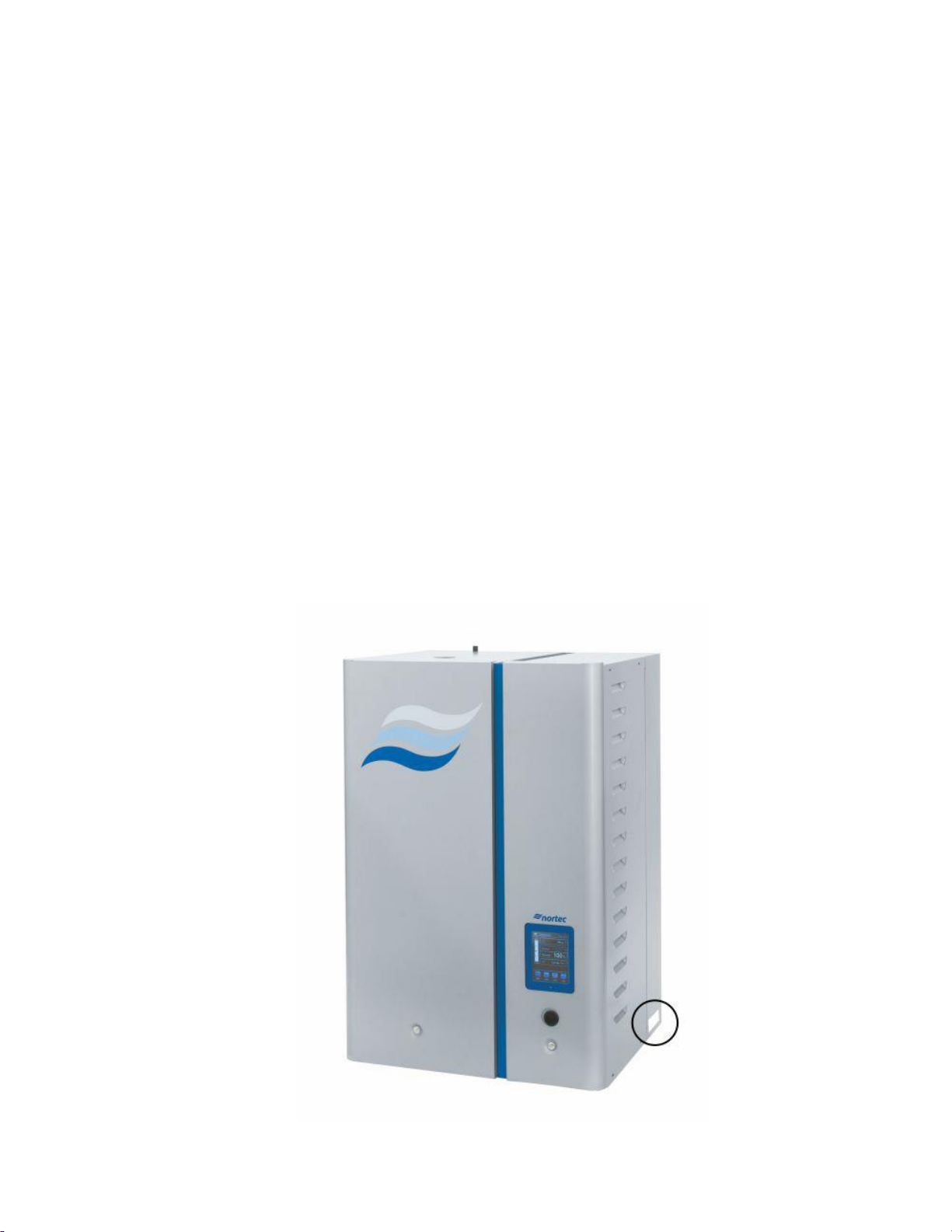
Before Installation
1 Ensure that available voltage and phase corresponds with humidifier voltage and phase as
indicated on humidifier’s specification label.
2 Ensure that the dedicated external fuse disconnect is of sufficient size to handle the rated
amps as indicated on the specification label. Refer to local codes.
3 Report any discrepancy immediately to the site engineer.
4 Ensure sufficient clearances will be available as described in Location on page 11.
5 Ensure steam lines can be routed to distributor or blower pack as described in Steam Lines
and Condensate Return on page 16.
Figure 1: Specification Label Location
Introduction | 2
Page 6
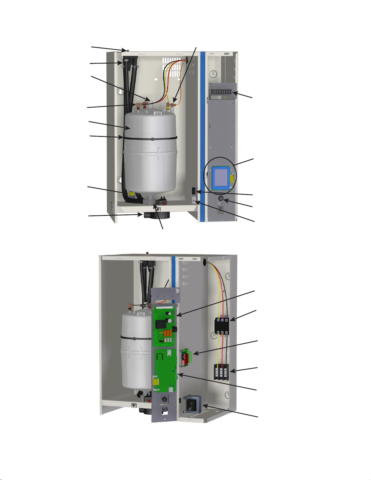
Steam Outlet
Condensate Return
Fill Cup
Drain Valve
Drain Canal
Fill Valve
Cylinder
Cylinder Strap
Cylinder Plug
High Water Sensor
Plug
Touch Screen Display
On/Off Switch
Auxiliary Drain Switch
Door Interlock Switch
Driver Board
Remote Relay Board
Contactor
High Voltage
Terminal Block
Transformer
Integrated Controller
Control Terminal
Strip
NOTE:
NH-EL 005-030
shown, component
location may vary
slightly for other
models.
TEST
Humidifier Components
3 | Introduction
Figure 2: NH-EL Humidifier Components
Page 7

Component
Function of Component
Auxiliary Drain
Drains water from cylinder by activating drain valve. Note that initiating a
drain in this manner will not induce Drain Water Cooling.
Condensate Return
Provides a connection to return condensate to humidifier.
Contactor
Turns On/Off power to cylinder electrodes.
Control Terminal
Strip
Terminal strip for connecting external controls and blower pack to
humidifier.
Cylinder Plug
Power connectors to electrodes in cylinder.
Cylinder strap
Securely holds cylinder in place.
Cylinder
Holds electrodes in water. Current between electrodes generates heat used
to generate steam.
Touch Screen
Display
User interface for configuring the humidifier.
Door Interlock
Switch
Prevents contactor from engaging when door is removed (pull out to
override this safety feature while troubleshooting).
Drain Canal
Combines cylinder drain water and fill cup overflow into a single drain outlet.
Drain Valve
Drains water from cylinder.
Driver Board
Provides input and output connections to humidifier components.
Fill Cup
Provides an air gap for backflow prevention.
Fill Valve
Controls flow of water into humidifier.
High Voltage
Terminal Block
Primary power connection from remote disconnect to humidifier.
High Water sensor
Plug
Used to detect max water level in cylinder.
On/Off Switch
Turns power On/Off to humidifier controller. Note: Turn off humidifier
disconnect to shut off primary power to the humidifier.
Remote Relay
Board (option)
Provides a terminal strip to dry contacts which open/close to indicate the
humidifier is on, humidifying, needs service, or is in a fault condition.
Steam Outlet
Connect to steam line with steam hose.
Integrated
Controller
Controls all functions of the humidifier’s operation and provides user
interface for configuration of the humidifier.
Transformer
Steps primary voltage down to 24 VAC for the controller and internal
components such as the fill valve and drain valve.
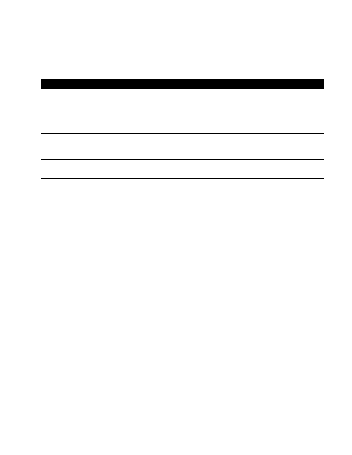
Description of Components
Table 1: Humidifier Components
Introduction | 4
Page 8
NH-EL 005-030 NH-EL 050-100 NH-EL 150-200
Fill Connections Drain Connections
NH-EL Models
The NH-EL with its Integrated Controller and state-of-the-art features and options is the most
advanced electrode steam humidifier available. As well as controlling the operation of the
humidifier, the Integrated Controller can be connected directly to BACnet and to the Internet.
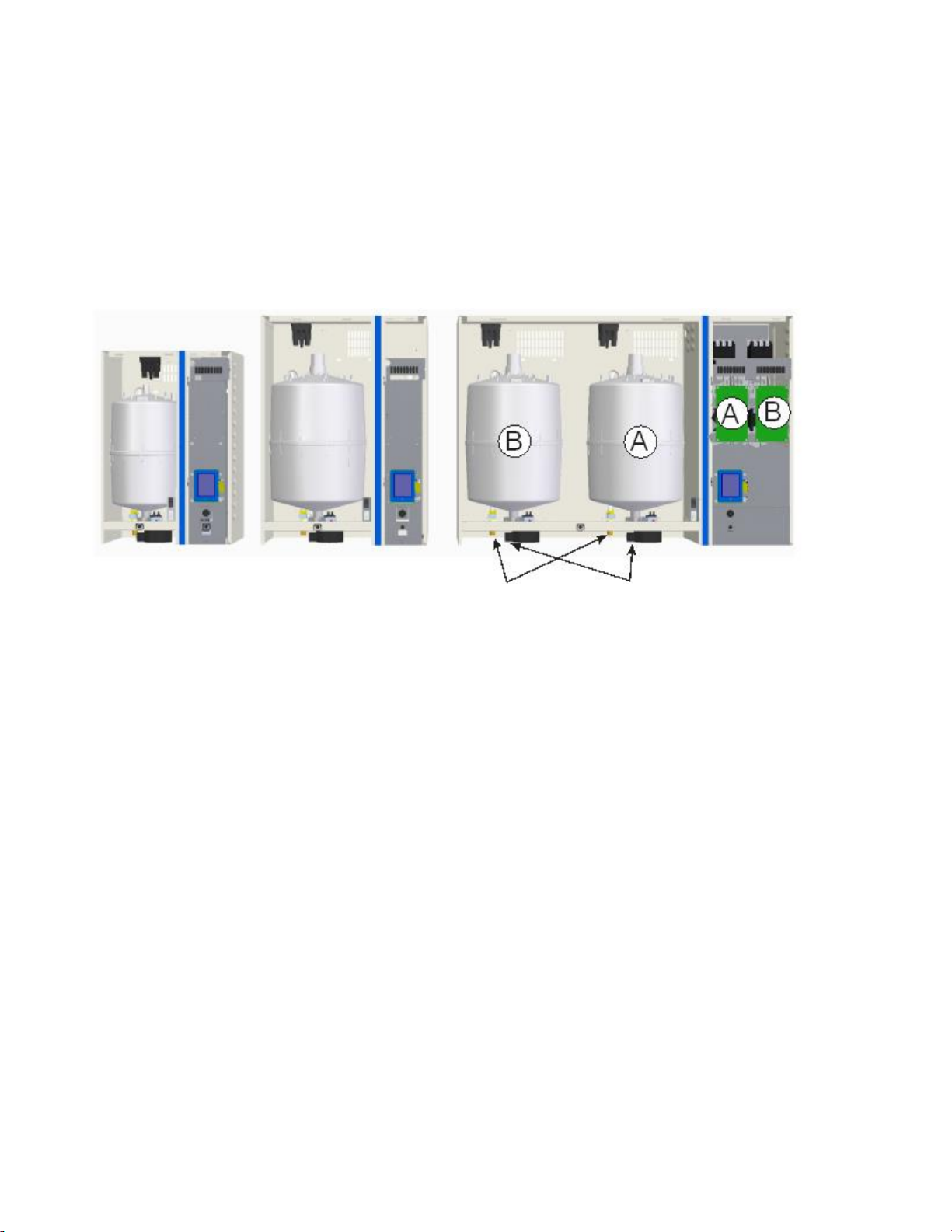
The NH-EL is available in capacities ranging from 5 lb/hr (2 kg/hr) to 200 lb/hr (90 kg/hr). NHEL humidifiers are packaged in three different cabinets depending on capacity. Figure 3: NH-EL
Sizes shows the configuration and relative size of the three different cabinets. NH-EL models up
to 100 lb/hr (45 kg/hr) are also available with a built on blower pack. Table 3 provides
specifications for the NH-EL product line.
Figure 3: NH-EL Sizes
Double Unit (NH-EL 150-200)
NH-EL double units have two cylinders to provide increased capacity. The construction and
installation of double units is identical to units with a single cylinder with the following
exceptions:
Double units have two driver boards (designated A and B). One driver board controls each
cylinder. (See Figure 3: NH-EL Sizes).
Double units can operate both cylinders in series or parallel from a single set of control
signals or independently based on two sets of control signals (see Double Mode (NH-EL 150-
200 only) on page 56 for configuration instructions).
Independent Operation - If configured for independent operation then 2 sets of control
wiring must be provided. Control wiring for each cylinder must be connected to the
cylinder’s corresponding driver board/terminal strip and each cylinder performs
independent of the other.
Parallel Operation - If configured for parallel operation then only one set of control wiring is
required and the cylinders operate in parallel. The advantage is even wear on both cylinders.
Series Operation – If configured for series operation, then only one set of control wiring is
required and the cylinders operate in series. Cylinder A’s output range is 0-50% and
Cylinder B’s output range is 50-100%. The advantage is the lower turndown ratio of one
cylinder.
Double units have one primary power connection but have individual fill, drain, and steam
outlet connections for each cylinder.
5 | Introduction
Page 9
Option / Accessory
Application
Steam Distributors
Adding steam into air ducts.
Remote Blower Pack
Adding steam into a space remote from the humidifier.
SAMe Steam Distribution Manifold
Adding steam into air ducts where short absorption is required.
Digital or Analog Control Humidistats
Controlling the output of the humidifier based on sensed RH (can
be mounted in the space being humidified or in the duct).
Digital RH Transducers
Communicating RH in a space or duct to the humidifier.
Digital or Analog High Limit Humidistats
Preventing over humidification in a duct by shutting down or
throttling down the humidifier when duct RH gets high.
Air Proving Switches
Ensuring humidification only occurs when air is moving in a duct.
Fill Cup Extension
Increasing the steam back pressure capability of an NH-EL.
Drain Water Cooling (Extreme)
Cooling drain water to less than 120 °F (49°C).
Foam Detection Kits
Increasing the range of water quality in which an NH-EL can
operate.
Options and Accessories
NORTEC provides a complete line of options and accessories for every humidification
application. The following options and accessories are available and may have been delivered
with your NH-EL humidifier. Refer to the installation instructions that came with the accessories
for the proper installation and operation.
Table 2: Options and Accessories
Introduction | 6
Page 10
Phase
Capacity
lb (kg)
Volts
NH-EL
Part No.
Amps
Max
Ext
Fuse
KW
Stand-
ard
Cylinder
Fill
gal (l)
per min
Net/Full
Weight
lb (kg)
1
5 (2.3)
110-120
2573379
15.6
20
1.9
202
0.13 (0.5)
45/55
(21/25)
10 (4.5)
208
2573380
18.3
25
3.8
202
0.13
(0.5)
220-240
2573382
15.9
20
3.8
202
277
2573383
13.7
20
3.8
202
440-480
2573385
7.9
15
3.8
204
550-600
2573386
6.3
15
3.8
204
20 (9)
208
2573388
36.6
45
7.6
321
0.13
(0.5)
45/65
(21/30)
220-240
2573389
31.7
40
7.6
321
277
2573390
27.5
35
7.6
321
440-480
2573392
15.9
20
7.6
309
550-600
2573393
12.7
20
7.6
309
3
20 (9)
208
2573394
21.1
30
7.6
303
0.13
(0.5)
220-240
2573395
18.3
25
7.6
303
440-480
2573397
9.2
15
7.6
311
550-600
2573398
7.3
15
7.6
311
30
(13.5)
208
2573399
31.7
40
11.4
421
0.3
(1.2)
45/80
(21/37)
220-240
2573400
27.5
35
11. 4
421
440-480
2573402
13.7
20
11.4
411
550-600
2573403
11.0
15
11.4
411
50
(22.5)
208
2573404
51.9
70
18.7
621
0.5
(2.0)
85/150
(39/68)
220-240
2573405
45.0
60
18.7
621
440-480
2573407
22.4
30
18.7
605
550-600
2573408
18.0
25
18.7
605
75 (34)
208
2573409
77.9
100
28.1
621
0.5
(2.0)
220-240
2573410
67.4
90
28.1
621
440-480
2573412
33.8
45
28.1
605
550-600
2573413
27.0
35
28.1
605
100 (45)
208
2573414
94.4
125
34.0
621
0.9
(3.3)
220-240
2573415
90.0
125
37.4
621
440-480
2573417
45.0
60
37.4
605
550-600
2573418
36.0
45
37.4
605
150 (68)
208
2573419
155.8
200
56.1
621
0.5**
(2.0**)
120/245
(55/112)
220-240
2573420
135.0
175
56.1
621
440-480
2573422
67.4
90
56.1
605
550-600
2573423
54.0
70
56.1
605
200 (90)
208
2573424
188.7
250
68.0
621
0.9**
(3.3**)
220-240
2573425
180.0
225
74.8
621
440-480
2573427
90.0
125
74.8
605
550-600
2573428
72.0
90
74.8
605
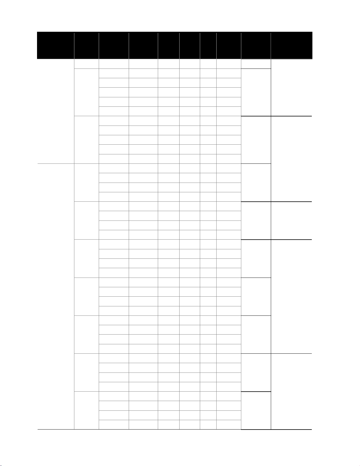
Table 3: NH-EL Specifications
** Note: Per cylinder basis.
7 | Introduction
Page 11
Phase
Capacity
lb (kg)
Volts
NH-EL
Space
Part No.
Amps
Max
Ext
Fuse
KW
Stand-
ard
Cylinder
Fill
gal (l)
per min
Net/Full
Weight
lb (kg)
1
5 (2.3)
110-120
2573429
17.2
25
2.0
202
0.13 (0.5)
83/93
(38/42)
10 (4.5)
208
2573430
19
25
4.0
202
0.13
(0.5)
220-240
2573431
16.5
25
4.0
202
277
2573432
14.2
20
4.0
202
440-480
2573434
8.2
15
4.0
204
550-600
2573435
6.6
15
4.0
204
20 (9)
208
2573436
37.3
45
7.8
321
0.13
(0.5)
83/103
(38/47)
220-240
2573437
32.3
40
7.8
321
277
2573438
28
35
7.8
321
440-480
2573440
16.2
20
7.8
309
550-600
2573441
13
20
7.8
309
3
20 (9)
208
2573442
21.8
30
7.8
303
0.13
(0.5)
220-240
2573443
18.9
25
7.8
303
440-480
2573445
9.5
15
7.8
311
550-600
2573446
7.6
15
7.8
311
30
(13.5)
208
2573447
32.4
40
11.7
421
0.3
(1.2)
83/118
(38/54)
220-240
2573448
28.1
35
11.7
421
440-480
2573450
14
20
11.7
411
550-600
2573451
11.3
15
11.7
411
50
(22.5)
208
2573452
52.6
70
18.9
621
0.5
(2.0)
123/188
(56/85)
220-240
2573453
45.6
60
18.9
621
440-480
2573455
22.7
30
18.9
605
550-600
2573456
18.3
25
18.9
605
75 (34)
208
2573457
78.6
100
28.3
621
0.5
(2.0)
220-240
2573458
68
90
28.3
621
440-480
2573460
34.1
45
28.3
605
550-600
2573461
27.3
35
28.3
605
100 (45)
208
2573462
95.1
125
34.5
621
0.9
(3.3)
220-240
2573463
90.6
125
37.7
621
440-480
2573465
45.3
60
37.7
605
550-600
2573466
36.3
45
37.7
605
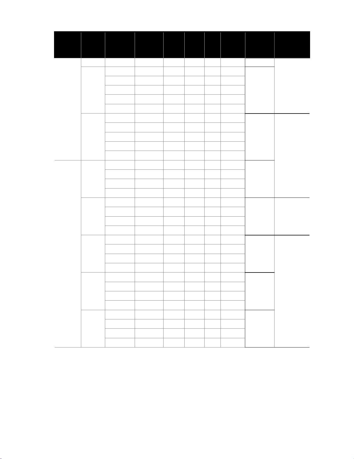
Table 4: NH-EL Space Specifications
Introduction | 8
Page 12

Installation
10 Typical Humidifier Installation
11 Location
13 Mounting with Keyholes
14 Plumbing
15 Steam Distributor
16 Steam Lines and Condensate Return Instructions
21 Electrical
22 External Controls
22 Control Wiring
22 Control Location
24 On/Off Control Wiring
25 Keep Warm Wiring
26 Modulating Control Wiring
28 Transducer Control Wiring
29 Double Unit Control Wiring
33 Remote Fault Option Wiring
34 Multi Mode Wiring
35 Modbus Digital Control
36 Options and Accessories
37 Fill Cup Extension
37 Extreme Drain Water Cooling
37 Condensate Cooling (External)
37 Foam Protection
37 Internal Fusing
37 Remote Fault Indication
9 | Installation
Page 13
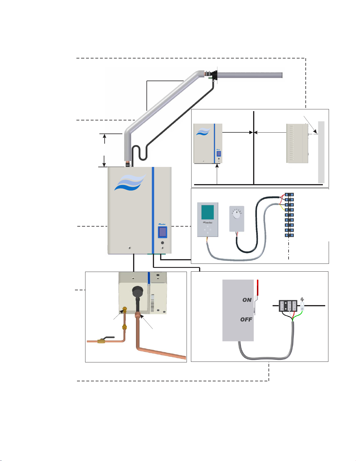
Typical Humidifier Installation
6 in.
(15 cm)
min.
right
clearance
36 in. (90 cm)
min. front
clearance
24 in.
(60 cm)
min.
3 in. (7.5 cm) Screws
1- 24 VAC
2- Security Loop
3- Common
4- Channel 1
5- Channel 2
6- 5 VDC
7- Ground
8- Blower Pack
9- Blower Pack
On/Off
Controls
Modulation
Controls
E
X
T
E
R
N
A
L
N
H
E
L
L1L2L3
Ground
Dedicated
Circuit
Breaker or
Disconnect
NH-EL
EXTERNAL
Cold potable water
150-1200 microsiemens
30-80 psig
Air Gap
½ in NPT
2 in.
(5 cm)
min.
1ft (30 cm)
1 ft (30 cm)
min.
1 – 24 VAC
2 – Security Loop
3 – Common
4 – Channel 1
5 – Channel 2
6 – 10 VDC
7 – Ground
8 – Blower Pack
9 – Blower Pack
0” (0 cm)
right
clearance
6” (15 cm)
recommended
Mounting
Pg 13
Steam
Distribution
Pg 15
Controls
Pg 22
Plumbing
Pg 14
Electrical
Pg 21
Figure 4: Typical Humidifier Installation
Installation | 10
Page 14
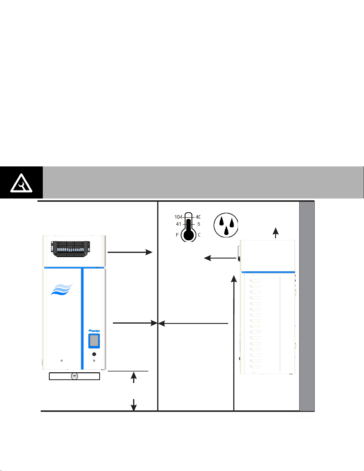
6 in.
(15 cm)
Recommended
Side
Clearance
36 in. (91.5 cm)
Min. Front Clearance
24 in.(61 cm)
Min Height
Mount Humidifier
Level
5-95%
(See Table for
Blowerpack
clearances)
(See Table for
Blowerpack
clearances)
(See Table for
Blowerpack
clearances)
If Blowerpack is used,
mount so that the steam
outlet is at least
96 in. (244 cm)
above ground level.
Note: Do not mount on hot surfaces, where freezing can occur, vibrating surface, or
floor.
Location
Mount on a suitable wall or vertical surface. Do not sit the unit on the floor to allow
clearances required for plumbing and electrical connections.
Clearance dimensions shown are for reference only and are the minimum required for
maintenance of the humidifier. Consult local and national codes before final location and
installation. NORTEC does not accept responsibility for installation code violations.
Install only in areas with ambient temperature 41-104 °F (5 – 40 °C) relative humidity 5 -
95% (non condensing).
When possible install the humidifier below the steam distributor. Take care to provide proper
steam line routing and proper condensate traps.
DO NOT locate the humidifier any further than absolutely necessary from the steam
distributor location. Net output will be reduced as a result of heat loss through the steam
line.
When possible, mount the NH-EL humidifier at a height convenient for servicing.
11 | Installation
Figure 5: Mounting Location / Clearance
Page 15
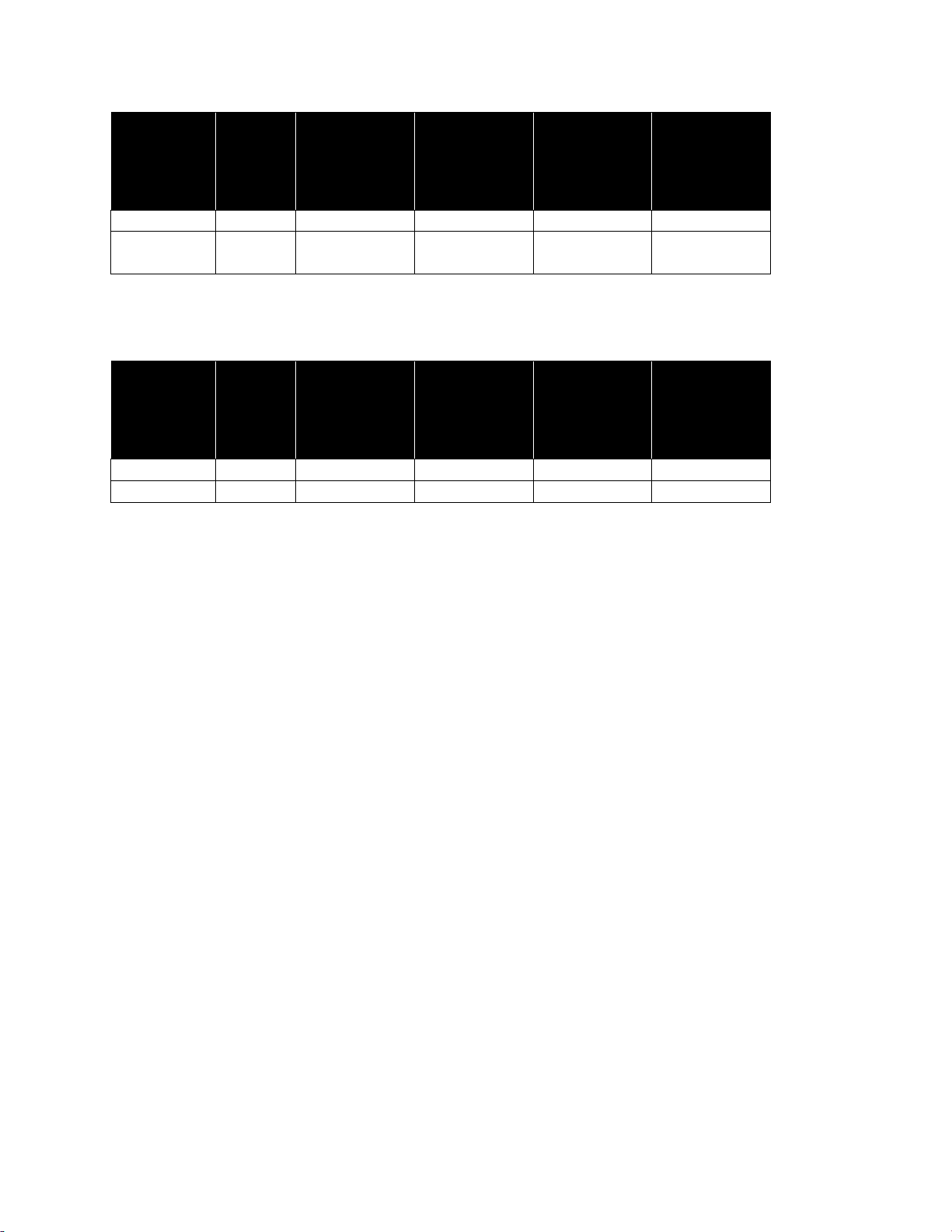
Humidifier
Capacity
lbs/hr (kg/hr)
Minimum
No. of
Blower
Packs
Min. Frontal
Clearance
Inches (cm)
Min. Overhead
Clearance
Inches (cm)
Min. Left side
Clearance
Inches (cm)
Min. Right side
Clearance
Inches (cm)
30 (13.6)
1
132 (336)
12(31)
12 (31)
12 (31)
100 (45.4)
1
Not
recommended
Not
recommended
Not
recommended
Not
recommended
Humidifier
Capacity
lbs/hr (kg/hr)
Minimum
No. of
Blower
Packs
Min. Frontal
Clearance
Inches (cm)
Min. Overhead
Clearance
Inches (cm)
Min. Left side
Clearance
Inches (cm)
Min. Right side
Clearance
Inches (cm)
30 (13.6)
1
120 (305)
12(31)
12 (31)
12 (31)
100 (45.4)
1
248 (630)
36 (91)
30 (76)
30 (76)
Table 5: Clearances for Blower Packs on Low Speed*
Table 6: Clearances for Blower Packs on High Speed*
*NOTES:
Nominal Conditions 72˚F (22.2˚C), 43% RH.
Low speed not recommended for 100 lbs/hr humidifier. Consult factory for recommendations.
Blower Pack should not be installed near cold surfaces or where dew point may be reached.
Higher humidity or lower room temperature may result in longer absorption distances.
Installation | 12
Page 16
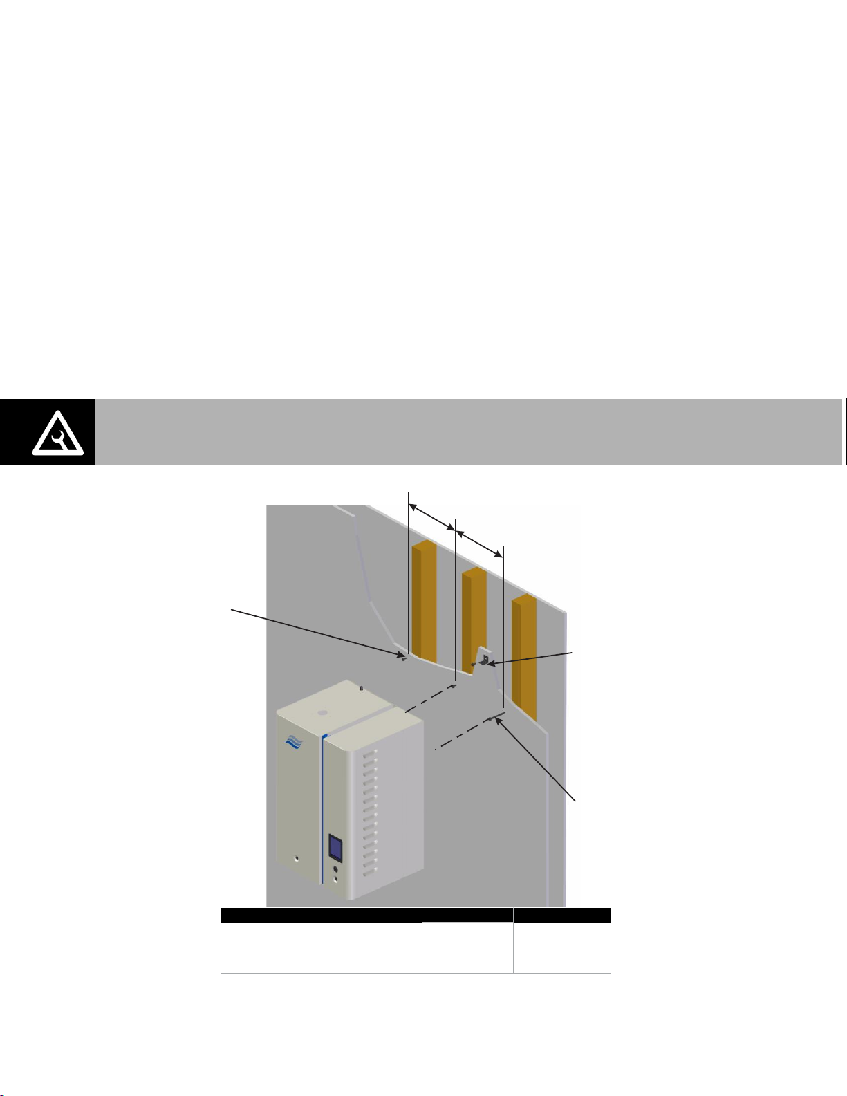
B
A
Install “L” brac ket
after hanging
humidifier
#12 x 3 in. (7.5 cm)
Wood Screws
Insert screws so that
1/4 in. (6 mm) exposed,
hang unit, tighten
screws.
Unit Size Screws Dim A in (cm). Dim B in. (Cm)
5-30 2 11.9 (30.2) -
50-100 2 16 (40.6) -
150-200 3 16 (40.6) 16 (40.6)
SPACESPACE
SPACESPACE
Mounting with Keyholes
1 The NH-EL Series humidifier is wall mounted using keyholes located on the back of the unit
cabinetry.
2 Use #12 x 3 in. (7.5 cm) screws mounted into 2x4 studs or better. Two screws are needed
for a single unit (NH-EL 010 to 100). Three screws are needed for a double unit (NH-EL 150
to 200).
3 Keyholes are spaced 16 in. (40.6 cm) apart center to center for large units and 11.9 in.
(27.2 cm) apart for small units. Insert screws into the studs until there is 1/4 in. of screw
exposed. Be sure the screws are level to each other.
4 Raise the unit and place the screws through the keyholes. Make sure the unit is level, then
tighten the screws to secure the unit in place.
5 Place “L” Shaped brackets on top of the unit, with holes inline with the studs. Using the
appropriate sized wood screw, fasten the “L” brackets to the studs, securing the unit from
any upward motion. See Figure 6: Mounting with Keyholes.
Note: Use screws longer than 3” (7.5 cm) if drywall or other spacer is present.
13 | Installation
Figure 6: Mounting with Keyholes
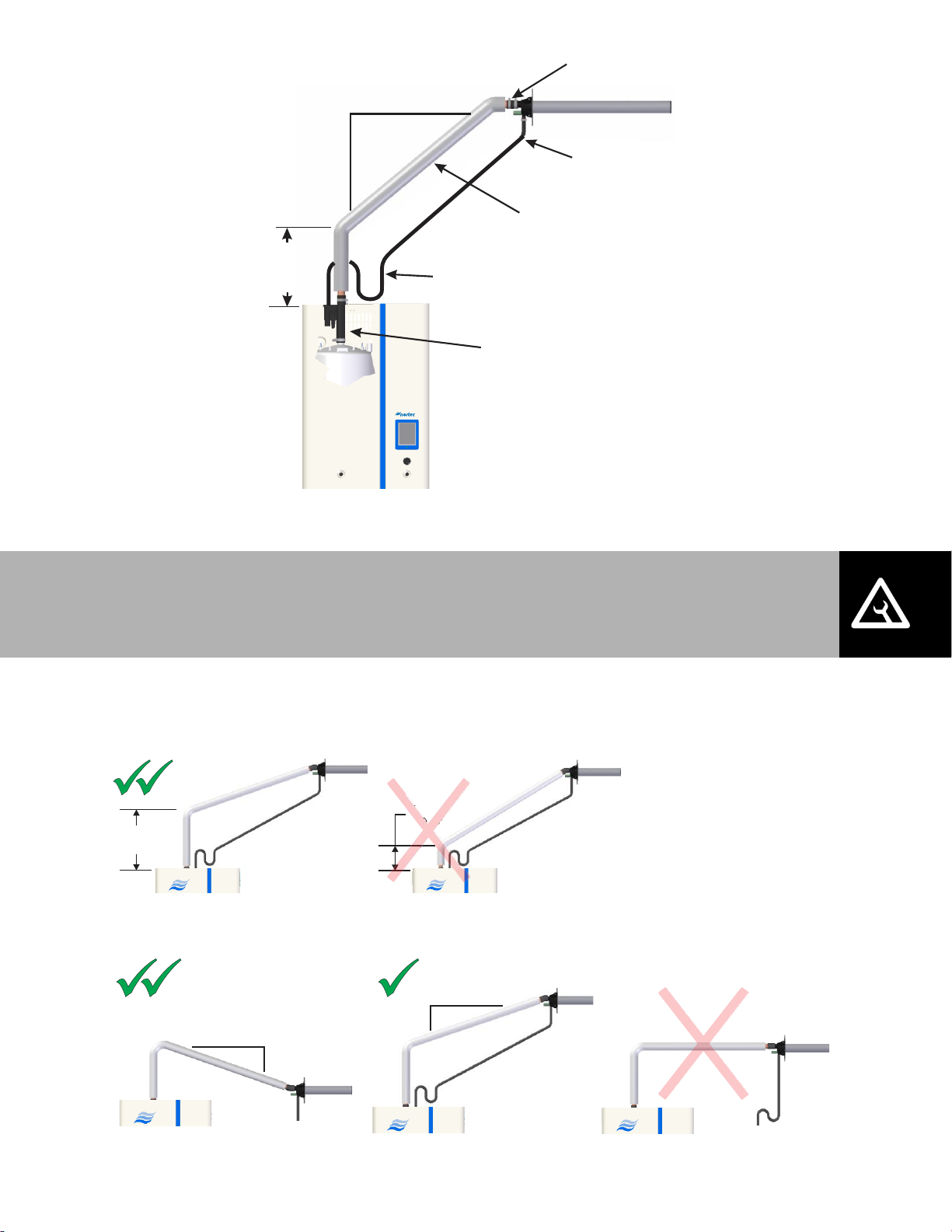
Page 17
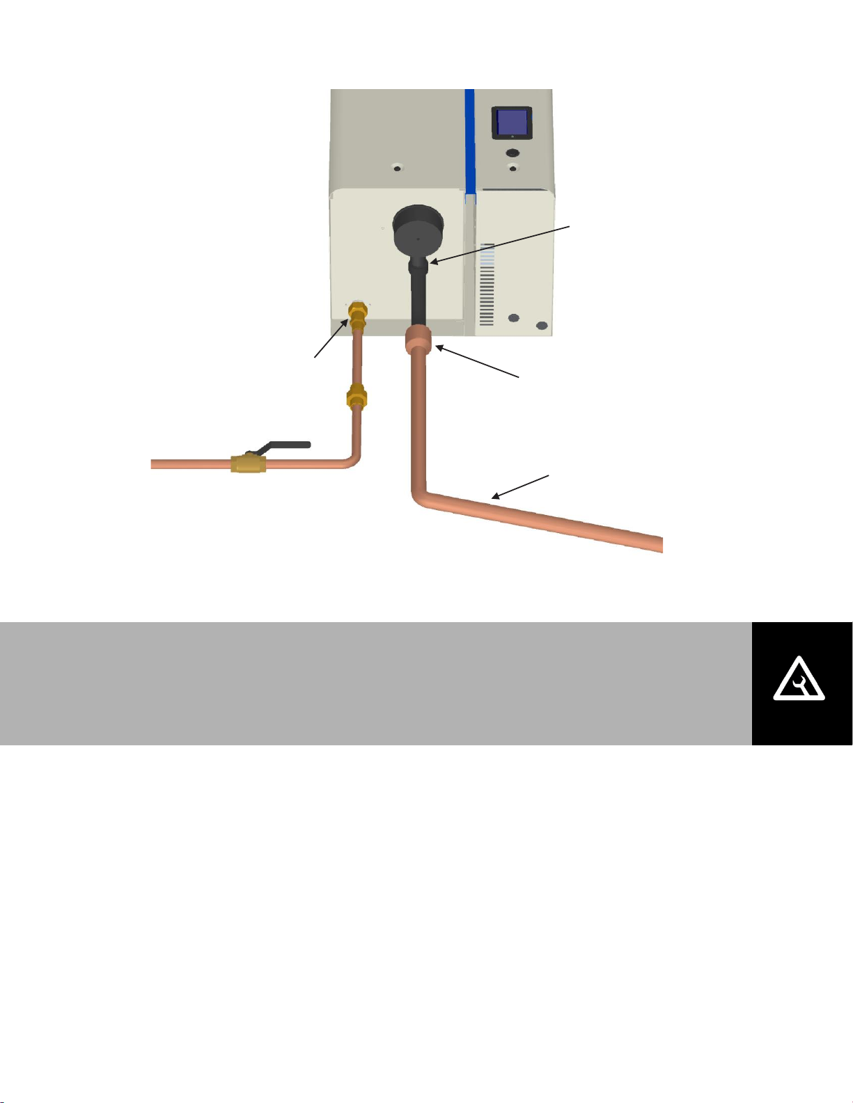
Min. 7/8 in. OD drain line.
Keep as short as possible.
Slope down to floor
drain or main drain.
Increase size if combining
multiple drains as in double unit.
1.2 in. (30 mm). OD
un-threaded outlet
with factory supplied
bent hose and clamp.
Air gap required.
2 1/2 in. to 7/8 in. copper
reducer is ideal.
(NORTEC option P/N 2522172)
Hose must not touch
the bottom of the funnel.
Always install a water
shut-off valve.
1/2 in. NPT
Use union to connect
supply pipe to unit.
*Pipe and water shut-off valve not supplied by NORTEC.
Note:
Use material suitable for 212°F (100°C) for drain and condensate lines.
Plumbing
Drain Water is very hot, do not drain to public sink
Supply cold potable water (not Reverse Osmosis or Demineralized). Conductivity:
150–750 microsiemens and pressure: 30-80 PSIG.
All water supply and drain line connections should be installed in accordance with local
plumbing codes.
Supply water should at 30 to 80 PSIG and be between 150-750 microsiemens (Hardness
0-12 GPG). For 750-1200 microsiemens, please consult factory.
Install water shut off valve and union before humidifier to facilitate servicing.
The drain line should not end in a sink used frequently by personnel, or where plumbing
codes prohibit. Route to a floor drain or equivalent for safety reasons.
Ensure drain line is adequately sized to provide free and easy draining and that an air gap is
installed as shown. A restricted drain can cause cylinder water to over concentrate,
resulting in poor operation or result in water backing up at the air gap.
Figure 7: Water Supply and Drain Connection
Installation | 14
Page 18
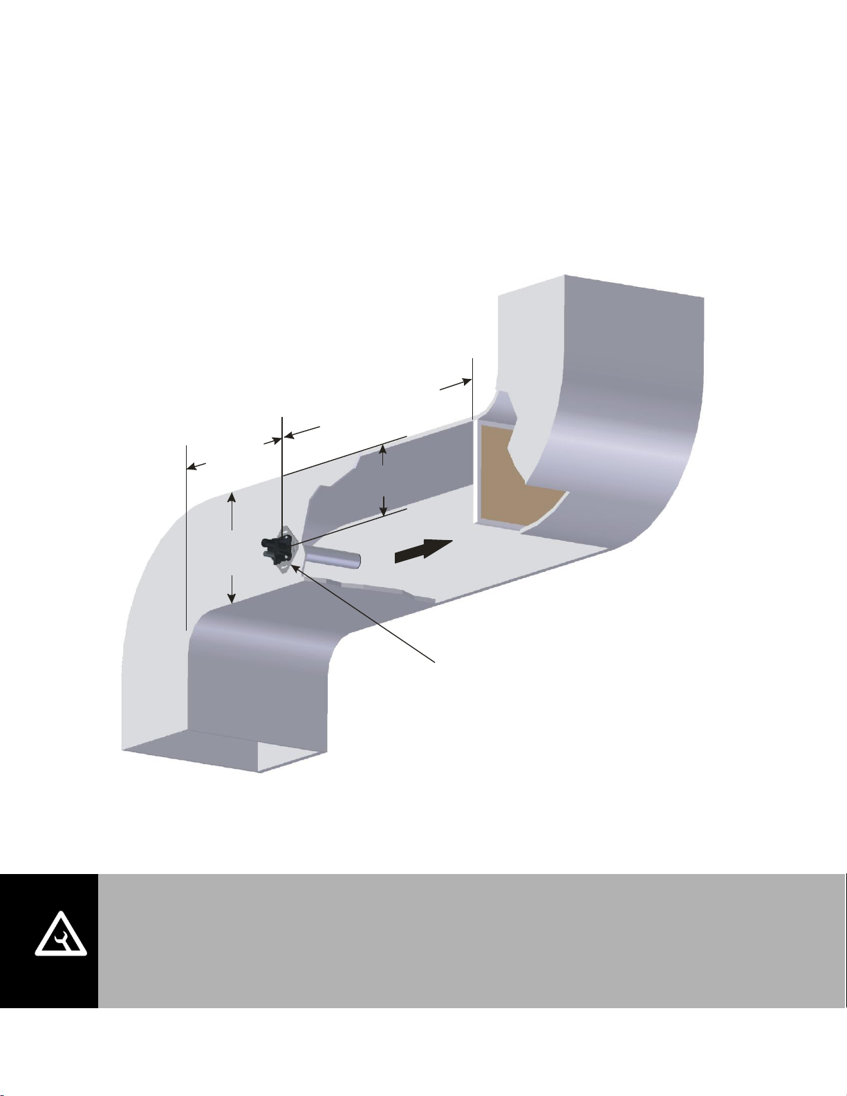
12 in.
(30 cm)
min.
Calculated absorption
distance to any obstruction
or 8-10 ft (2.4 - 3 m)
if unknown
Mount distributor
to side of duct
2 x duct
height min.
2/3 Duct
height
Note:
Steam Distributor
Steam generated by the NH-EL may be distributed directly into a space with a built on or
remote blower pack, or into an air handling system using either Nortec steam distributors or
Nortec’s SAMe steam distribution manifold.
Whichever method is used, the steam distributor should be installed as close as possible to
the humidifier. Short steam distribution lines minimize condensate losses and the possibility
of generating back pressure in the steam distribution line.
Figure 8: Distributor Location in Duct provides common guidelines for locating a steam
distributor in a duct.
Figure 8: Distributor Location in Duct
Install the NH-EL as close as possible to whatever steam distributor is used.
Refer to distributor, SAMe, or remote blower pack installation manuals for detailed installation
instructions.
15 | Installation
Page 19
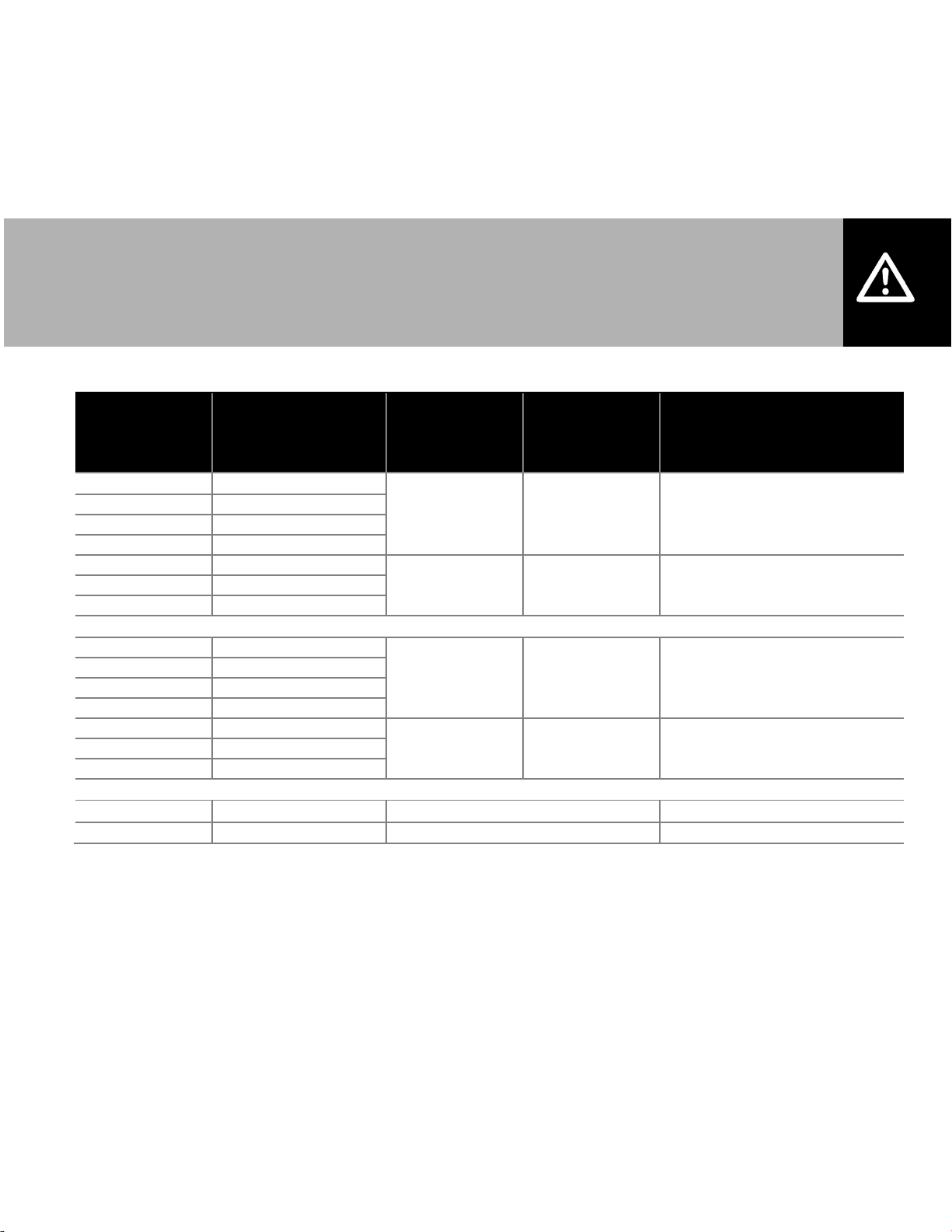
NH-EL
Maximum Steam
MED-L
Stainless
Possible Steam Losses
Model
Line Length
Copper
Steel
(based on 1” insulated copper pipe)
ft
(m)
Tube
Tube
lb/hr/ft
(kg/hr/m)
5
7
(2)
3/4
0.875 X 0.049W
0.06
(0.09)
10
12
(3.5)
20
17
(5)
30
22
(6.5)
50
43
(13)
1 1/2
1.75 X 0.065W
0.11
(0.16)
75/150**
47
(14)
100/200**
50
(15)
Oversized Steam Line (Use for longer steam runs)***
5
14
(4)
1
1.125 X 0.049W
0.06
(0.09)
10
24
(7)
20
34
(10)
30
44
(13)
50
86
(26)
2
2.0 X 0.065W
0.11
(0.16)
75/150**
94
(28)
100/200**
100
(30)
Nortec Steam Hose
5-30
10
(3)
Pt No 1328810 (7/8”)
0.1
(0.15)
50-200**
10
(3)
Pt No. 1328820 (1 3/4”)
0.15
(0.22)
Danger:
Steam Lines and Condensate Return Instructions
The following instructions must be followed for installation of steam lines for ASD, BSD, CSD,
SAM-e, and remote blower packs. Failure to use material recommended in
Table 7, exceeding maximum recommended length in Table 7, or failure to follow any other
steam line installation instructions will result in improper operation and could void the warranty.
The NH-EL is an atmospheric humidifier that will only operate properly when its steam
distribution system is installed so that it provides no significant backpressure.
Installing the NH-EL in such a way that backpressure can develop during operation
could result in serious injury or damage to property.
Table 7: Recommended Steam Line Material*, Maximum Length, Losses
Note: * The use of steam line other than copper, stainless steel tube or Nortec supplied steam line will void the warranty and may
adversely affect the operation of the humidifier.
** Use one steam line per cylinder for NH-EL 150-200 humidifiers. Do not combine lines except at distributor using a Nortec adapter
designed for that purpose and only if humidifiers operate in parallel.
*** These diameters require a reducer at humidifier and steam distributor connection.
Installation | 16
Page 20
Ste
am
D
irectio
n
Ste
a
m Dir
ectio
n
S
t
e
a
m
D
i
r
e
c
t
i
o
n
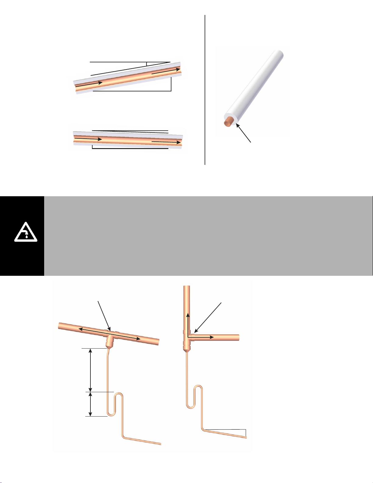
2 in.
(5 cm)
1 ft (30 cm)
1ft (30 cm)
0.5 in.
(12 mm)
10 Degrees
2 Degrees
Use Appropriate Slope Insulate Pipe
1 in. (2.5 cm) pipe
insulation
Minimal Slope (up)
Minimal Slope (down)
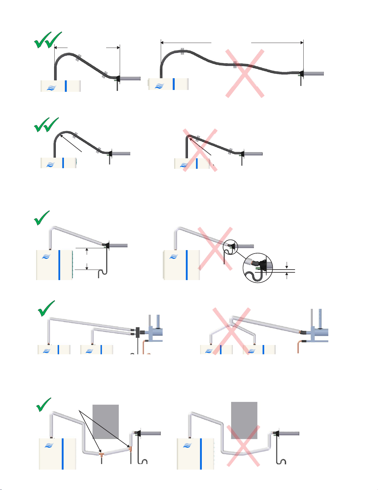
Figure 9: Steam Line Slope and Insulation
Trap condensate
12 in. (30 cm)
min drop to
top of ‘P’ Trap
P Trap min
6 in. (15 cm)
or
duct static
pressure + 2 in
whichever is
greater
Tee is same size
as steam line
Use a full size tee, not a 90
degree elbow for vertical
to horizontal transitions.
‘P’ Traps Use:
- NORTEC 0.375 in condensate hose
- 1/4 in Med-L copper tubing, or
- 0.375 in stainless steel tubing
Condensate drains must be sloped down.
1 ft (30 cm)
0.25 in
(0.6 cm)
Trap at all low points and recommended intervals using full size ‘T’ for traps.
Condensate should not be routed to a sink used frequently by personnel. Route to a floor
Route condensate to floor drain or equivalent in multi-unit to single SAM-e installation.
17 | Installation
drain or equivalent. Condensate normally cools in traps but is still hot. A SAMe or larger
steam line generates more condensate and water may not cool in the trap. A drain water
cooler option may be installed if required by code.
Figure 10: Condensate Traps
Page 21
Hose cuff
with clamps
2 in. (5 cm)
min.
1 ft (30 cm)
‘P’ Trap
1 ft (30 cm)
min. before
any bend
Condensate line
Route to fill cup or drain .
Use steam hose and clamps
between cylinder and steam line.
Insulated copper
steam line. Support
so weight is not on
cylinder.
Never
1 ft (30 cm)
min.
< 1 ft
(30 cm)
Best
Never
< 1 ft
(30 cm)
Best
Good
Never
Never
1 ft (30 cm)
min 0.5 in.
(12 mm)
1 ft (30 cm)
min 2 in.
(5 cm)
Steam Line Rules
Figure 11: Typical Steam Line Installation
The following 10 points provide rules for installing steam lines connecting the NH-EL
humidifier to ASD, BSD, CSD, SAMe and remote blower packs. In addition to these rules
never use unapproved material for steam lines.
1. Allow minimum of 12 in. (30 cm) before first bend in steam line.
2. Slope the steam lines.
Installation | 18
Page 22
> 10 ft (1.5 m)
Never
< 5 ft (1.5 m)
Note: 1) Always support hose. 2) Do not exceed 10 ft (3 m) hose length
Best
Best
Never
12 in.
(30 cm)
min. Radius
< 12 in.
(30 cm)
Radius
Never
< 12 in.
(30 cm)
Radius
Good
min. 12 in.
(30 cm)
Never
< 12 in.
(30 cm)
< 12 in.
(30 cm)
Good Never
Notes: 1. Units must operate in parallel.
2. Also for double units (cylinders must operate in parallel).
Condensate
Traps
Good
Never
3. Use steam hose only for short distances.
4. For steam hose maintain minimum 12 in. (30 cm) bend radius.
5. Install traps on condensate lines at least 12 in. (30 cm) below
connection.
6. Only combine steam lines at steam distributor with Nortec adapter.
7. Install condensate traps at low points and horizontal to vertical
transitions.
19 | Installation
Page 23
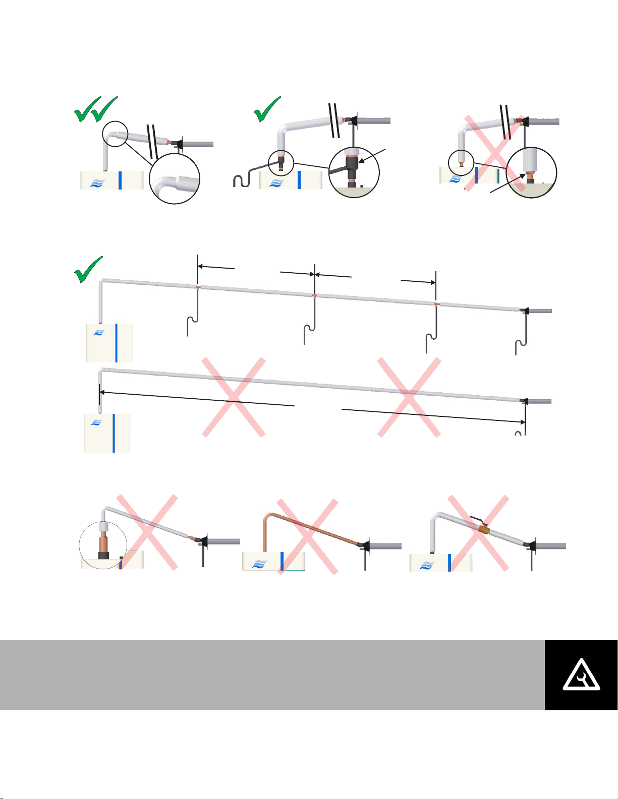
Best
Good Never
Nortec
Condensate
Trap
Sloping Down
Increase =
Condensate
Blockage
max. 15 ft
(4.5 m)
max. 15 ft
(4.5 m)
Never
> 15 ft
(4.5 m)
max. 15 ft
(4.5 m)
max. 15 ft
(4.5 m)
Good
Never
> 15 ft
(4.5 m)
Never
Install a valve or other obstruction
Never Never
Reduce Steam Line Size Install Copper or SST without Insulation
Never Never
Never
Never Never
Never
Never
After Installation Always:
Ensure all condensate lines / traps flow.
8. Increase diameter either on down slope or install condensate trap.
9. Install condensate traps if steam line > 15 ft (4.5 m).
10. In addition never:
Purge steam lines to remove any contaminants and installation materials
Installation | 20
Page 24
L1
L2
Ground
L1
L2
Ground .
L1
L2
L3
Neutral
Ground
L1
L2
L3
Neutral
Ground
L1
L2
Ground
L1
Neutral
Ground
L1
L2
L3
Neutral
Ground
L1
L2
L3
Ground
Three Phase NH-EL
Single Phase NH-EL
Single Phase Supply
Three Phase Supply
(Note: Load will be unbalanced)
Three Phase Supply
Dedicated
Circuit Breaker
or
Fused Disconect
Note:
1
2
3
4
Optional internal fuses are not
a substitute for external fuses.
Dedicated external fused
disconnect must be installed.
Fusing must not exceed max
circuit protection as indicated
on the specification label.
Ensure that adequate power is
available to carry full humidifier
amp draw as indicated on the
specification label.
All wiring to be in accordance
with national and local electrical
codes.
E
X
T
I
N
T
E
X
T
I
N
T
E
X
T
I
N
T
E
X
T
I
N
T
Three Phase Supply
(Note: Load will be unbalanced)
Electrical
Caution: Wiring to be performed by a licensed electrician.
21 | Installation
Figure 12: Primary Power Connection
Page 25
1
2 3
10 ft min.
Humidity
Control
(return air
duct or
location
representative
of the room)
Duct High
Limit
4
Out
door
temp.
sensor.
Air
Proving
Switch
Humidity
Control
(return air
duct or
location
representative
of the room)
Caution: Failure to wire the humidifier in accordance with the wiring instructions
could cause permanent damage. Such errors will void the warranty.
External Controls
Control Wiring
The following information is relevant to all controls, factory supplied or otherwise. For wiring use
a minimum of 18 AWG and keep as short as possible. The NH-EL humidifier can be operated
with two modulating inputs. Signal types must be the same (both demand or both transducer).
The NH-EL can also be operated as On/Off. See NH-EL Humidifier Configuration on page 54 for
configuration.
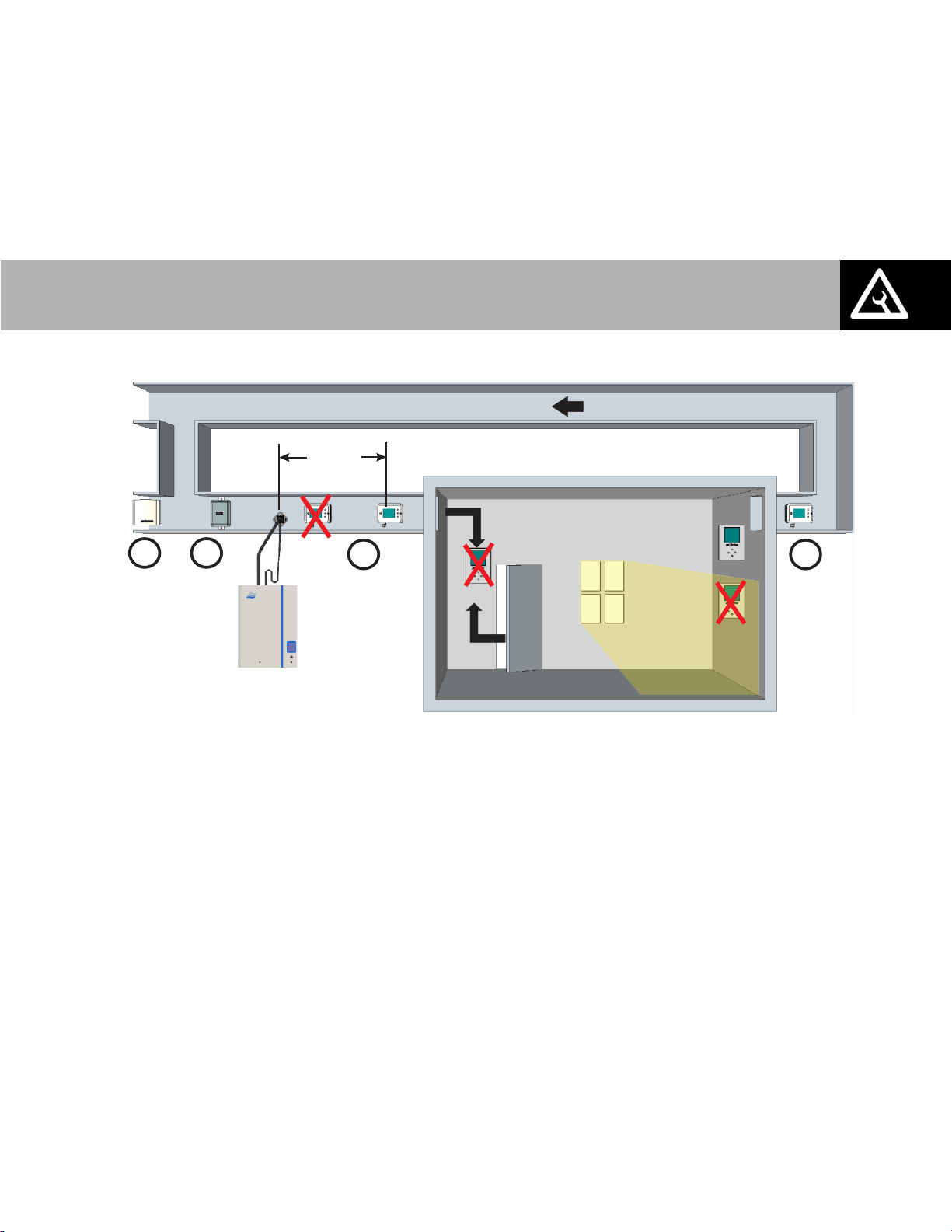
Control Location
Figure 13: Control Location (Duct Humidification)
Duct Humidification
1 Air Proving Switch
Locate so that it can sense air flow or lack of it.
2 Duct High Limit
NH-EL can be modulating, On/Off, or a humidity sensor.
Locate at least 10 feet from steam distributor or far enough that under normal conditions
steam is fully absorbed.
3 Humidity Control
NH-EL can be Modulating, On/Off, or a Humidity Sensor.
Can be located either in return air duct (preferred) or in room being humidified.
Mount in area representative of room humidity (draft, doorways, sunlight, or overhang such
as a shelf can affect reading). Avoid placing near discharge diffuser of humidified air.
4 Outdoor Temperature Sensor
Mount in area representing outdoor air temperature (makeup air duct, outside).
Installation | 22
Page 26

1
Humidity
Control
(in location
representative
of the space)
1
Humidity
Control
(in location
representative
of the space)
1
Humidity
Control
(in location
representative
of the space)
Note: Regardless of selecting on/off or modulating control method, Nortec humidifiers must have a
closed circuit across its security loop control terminal to operate. Nortec highly recommends the use
of a high limit humidistat and an air proving switch in series for this function.
Space Humidification
Figure 14: Control Location (Space Humidification)
1 Humidity Control
NH-EL can be modulating, On/Off, or a humidity transducer.
Locate in room being humidified but not in discharge zone of blower pack(s).
Mount on indoor wall in area representative of room humidity (draft, doorways, sunlight, or
overhang such as a shelf can affect reading).
2 High Limit Humidistat (not shown)
Install a high limit On/Off humidistat in area representative of room humidity.
3 Outdoor Temperature Sensor (not shown)
Mount outside in area representing air temperature.
23 | Installation
Page 27
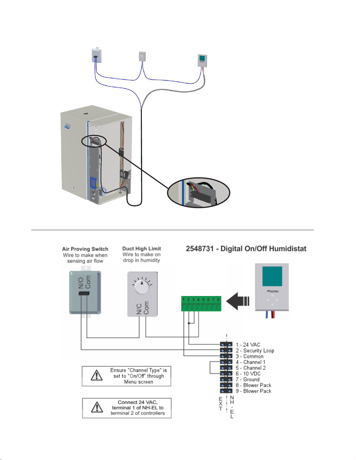
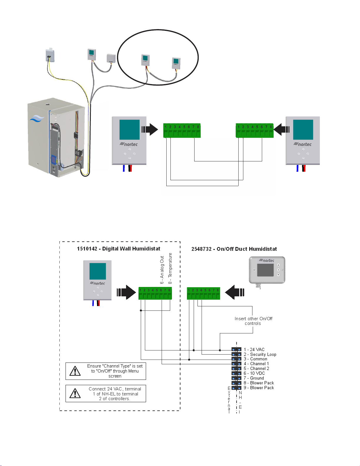
Figure 16: Digital On/Off Humidistat
Note: 1
2
3
4
Humidifier will run when circuit between
terminal 1 a n d 2 on h u midifier is closed.
T e rminal 1 is 24 VAC Hot, turn uni t o ff to
avoid shorting while wiring.
Digital Humidi stat requires 24 VAC power
from terminals 1 and 3 of humidifier.
2520273 - Digital On/Off Duct Humidistat
can also be used for duct high li mit. W ire
in series to 3 - Common and 4 - Digital Out
of the humidistat.
Humidifier Terminal Strip
Air Proving
Switch
Duct High
Limit
2548731 - Digital
On/Off Humidistat
1 – Common
8 – Temperature
On/Off Control Wiring
Figure 15: On/Off Controls
2 – 24 VAC
3 – Digital In
4 – Digital Out
5 – Fan Activation
6 – Fan Activation
7 – Temperature
Installation | 24
Page 28
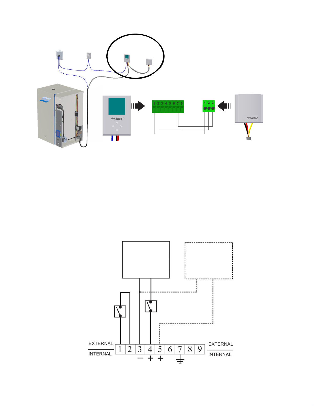
Air Proving
Switch
Duct High
Limit
Digital On/Off
Humidistat
Duct Sensor
1 - Common
2 - 24 VAC
3 - Analog Out
Wire remote sensor to digital display as shown below,
wire digital display to humidifier as shown above.
2520273 - Digital On/Off Duct Humidistat Package
1 - Ground
2 - 24 VAC
7 - Analog In
The security loop must
be closed for keep warm
to operate when the
humidifier is in standby.
Install an On/Off high
limit humidistat between
terminal 1 and 2.
Optional Modulating
Humidity Controller
Channel 2
Humidity Controller
Channel 1
Other On/Off
Controls
Figure 18: Keep Warm Wiring
1 – Common
7 – Analog In
Keep Warm Wiring
For the keep warm feature to work the security loop between terminal 1 and 2 on the low
voltage terminal strip must be closed. To accomplish this:
1 Install an On/Off high limit humidistat between terminal 1 and 2.
2 Install any other On/Off controls in series with the control signal connected to terminal 4
(Channel 1 control signal).
3 If desired a modulating high limit humidistat can also be installed and connected to terminal
5 (Channel 2 control signal).
2 – 24 VAC
Figure 17: Duct Sensor Wiring
25 | Installation
Page 29
Note: 1
2
3
4
Install On/Off controls or jumper between
terminal 1 a n d 2 o f h u midifier in order to run.
Terminal 1 is 24 VAC Hot, turn unit off to
avoid shorting while wiring.
High Limit Humidistat must be duct mounted.
It can be On/Off or modulating.
Control Humidistat can be mounted in space
or in return air duct and can be On/Off or
modula ting.
Air Proving
Switch
High Limit Humidistat
Control Humidistat
Humidifier Terminal Strip
SPACE
SPACE
Figure 20: Digital Modulating Humidistats
1 – Common
2 – 24 VAC
1 – Common
2 – 24 VAC
Analog Out -3
24 VAC – 2
Common – 1
Modulating Control Wiring
Figure 19: Modulating Controls
Installation | 26
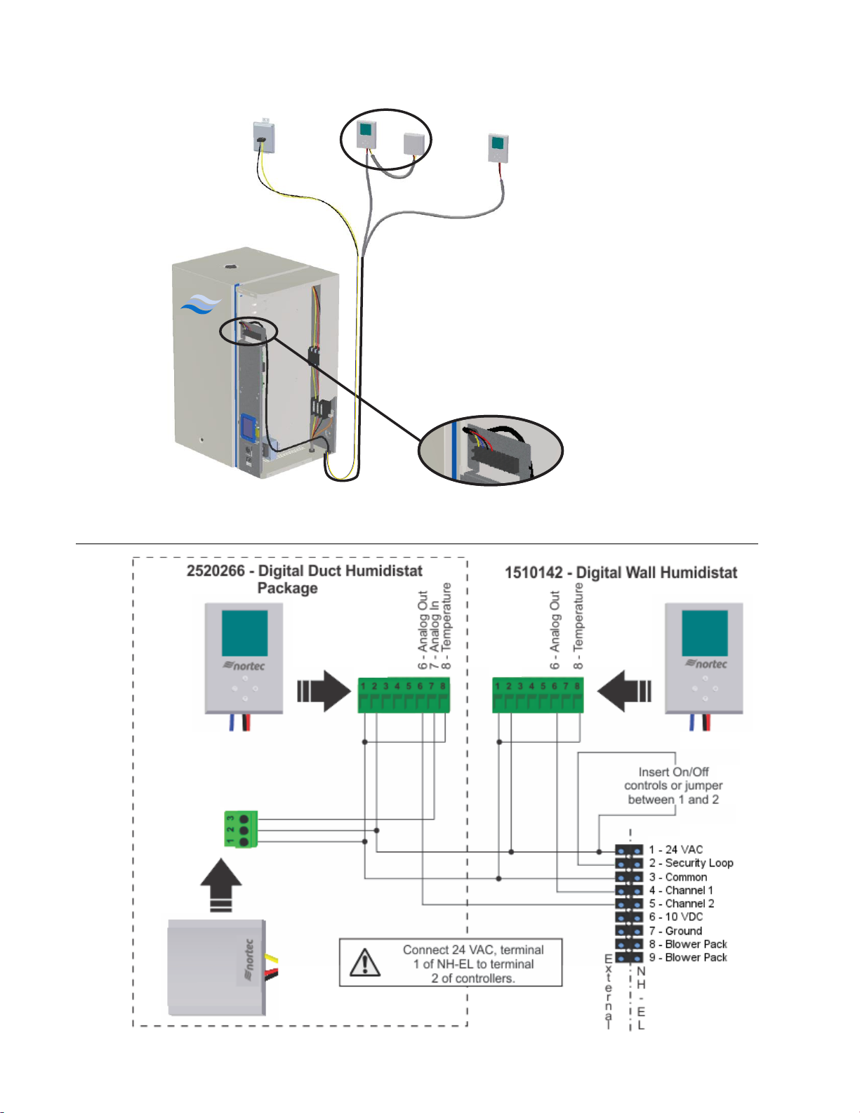
Page 30
Air Proving
Switch
Duct High
Limit
2520261 - Digital
Wall W/O Sensor
1509858 - Wall
Sensor
1 - Common
2 - 24 VAC
7 - Analog In
1 - Common
2 - 24 VAC
6 - Analog Out
Wire wall sensor to digital display as shown
below, wire digital display to humidifier as shown
for 1510142 - Digital Wall Humidistat.
+
1509858 - Wall Sen so r
2520261 - Dig ital Wall W/O Sensor
2520261 - Digital
Wall W/O Sensor
1509858 - Wall
Sensor
Figure 22: Digital Wall Humidistat - On/Off High Limit Duct Humidistat
1 – Common
2 – 24 VAC
1 – Common
8 – Temperature
Figure 21: Digital Wall Humidistat – Remote Wall Sensor
2 – 24 VAC
3 – Common
4 – Digital Out
7 – Temperature
27 | Installation
Page 31

Figure 24: Digital Transducers
Air Proving
Switch
Duct High Limit
1509857 - 2-10V Duct
Humidity Transducer
Humidity Control
1509858 - 2-10V Wall
Humidity Transducer
Note: 1
.
2
3
4
Install On/Off controls or jumper between
terminal 1 a n d 2 o f h u midifier
Terminal 1 is 24 VAC Hot, turn unit off to
avoid shorting while wi rin g .
Duct High limit can be duct humidity
transducer as shown or duct On/Off humidistat.
Humidity Control can be wall humidity
transducer as shown, duct humidity transducer,
or On/Off humidistat.
Humidifier Terminal Strip
1 – Common
3 – Analog Out
1 – Common
2 – 24 VAC
.
Transducer Control Wiring
Figure 23: Transducers
2 – 24 VAC
Installation | 28
Page 32
Connect all controls
to terminal block A
B
A
Double Unit Control Wiring
NH-EL double units (150-200) have two low voltage terminal blocks. The units can be
configured to operate the cylinders in series or parallel from one set of control signals, or
independently from two sets of control signals. See Double Mode (NH-EL 150-200 only) on
page 56 for more information.
Always select Parallel operating mode when connecting both cylinders to one SAM-e. Use
separate steam distributors for each cylinder if configured for sequence operation.
Parallel or Series - One set of control signals (Double Mode = Series or Parallel) wire the
controls to terminal block A.
Figure 25: Parallel or Series Mode Control Wiring (Double Unit)
29 | Installation
Page 33

Figure 26: Double Unit Parallel or Sequence Wiring
Double Unit Control Wiring (Continued)
Installation | 30
Page 34

Figure 28: Double Unit Independent Mode Wiring
Zone B (Cylinder B) Controls Zone A (Cylinder A) Controls .
Connect zone B
controls to
terminal block B
Connect zone A
controls to
terminal block A
B
A
1 – 24 VAC
2 – On/Off Loop
3 – Common
4 – Channel 1
5 – Channel 2
6 – 10 VDC
7 – Ground
8 – Blower Pack
9 – Blower Pack
1 – 24 VAC
2 – On/Off Loop
3 – Common
4 – Channel 1
5 – Channel 2
6 – 10 VDC
7 – Ground
8 – Blower Pack
9 – Blower Pack
Double Unit Control Wiring (Continued)
Independent– Two sets of control signals (Double Mode = Independent) wire the controls for
Zone A (cylinder A) to terminal block A and wire the controls for Zone B (cylinder B) to terminal
block B. All control signals must be the same type (Demand/Transducer).
Figure 27: Independent Mode Control Wiring (Double Unit)
31 | Installation
Page 35

Figure 30: Outdoor Temperature Sensor
SETPOINT LIMIT (%RH)
OUTDOOR TEMPERATURE
1 – 24 VAC
2 – On/Off Loop
3 – Common
4 – Channel 1
5 – Channel 2
6 – 10 VDC
7 – Ground
8 – Blower Pack
9 – Blower Pack
1 – Common
2 – 24 VAC
Outdoor Temperature Setback Sensor
Figure 29: Outdoor Temperature Reset
Each digital controller is equipped with an integrated reset function that can reduce the
setpoint during cold weather operation. This will prevent condensation on windows and
building structures. The above graph illustrates how the setpoint reset feature operates.
This feature is enabled by removing the jumper from terminals 8 and 1 on the humidistat
and wiring the outdoor temperature sensor to these terminals.
When the outdoor temperature setback feature is in effect, the humidistat will normally
display the calculated setpoint limit based on the outdoor air temperature. A snowflake will
also be displayed to indicate cold weather operation. When any key on the controller is
pressed, the LCD screen will display the customer specified setpoint for a short duration.
Installation | 32
Page 36

Steam
Unit ON
Error
Service
NO
COM
NO
COM
NC
NO
COM
NC
NO
COM
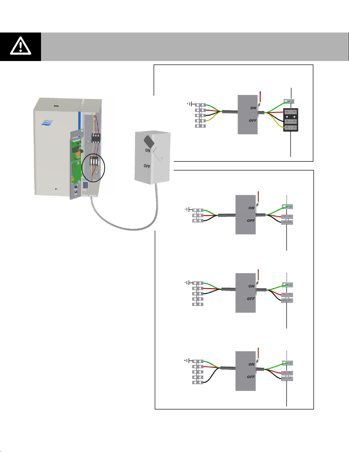
Remote Fault Option Wiring
The NH-EL remote fault option includes 4 relays that can provide remote status indication. The
relays are mounted to a remote fault board which is located as shown in Figure 31: Remote
Fault Wiring. The PCB with the relays includes markings which indicate the function of each
terminal on the board. The relays indicate the following status:
1 Unit On – The normally open relay is closed when the humidifier has power and the On/Off
switch is set to on.
2 Steam – The normally open relay is closed when the control board detects that the cylinder
is drawing current and steam is being produced.
3 Service – The relay can be wired to open (NC) or close (NO) when a warning is displayed on
the humidifier display and the yellow service LED is illuminated.
4 Error – The relay can be wired to open (NC) or close (NO) when a fault is detected by the
humidifier controls.
Figure 31: Remote Fault Wiring
33 | Installation
Page 37

Daisy chain pole 1 and 2
of terminal J10 of the
control board.
Do not reverse polarity.
Note:
Slave X
Daisy Chain
up to 16
Humidifiers
Master
Slave 1
Multi Mode Wiring
Connect up to 16 units (equivalent of 1600 lb/hr) using 18-24 AWG multi-strand, twisted
pair, shielded cable.
Connect humidistats/transducers and security loop to master unit only.
Jump the security loops on slave units.
When connecting double units connect only to driver board A.
See NH-EL Humidifier Configuration on page 54 and Multi on page 57 for software
configuration.
Figure 32: Multi Mode Wiring
Installation | 34
Page 38

BMS
Protocol
Signal Type
Recommended
Cable
Max. Recommended Distance
from Nortec Module to BMS
Modbus
EIA-485,
2-wire
18-24 AWG
Shielded, Twisted
Pair, 120 Ω*
Should not exceed 2200 ft
Item
Default
Adjustment Range
Signal Type*
EIA-485
-
Transmission Mode*
RTU
-
Baud Rate
9600
9600, 19200,
38400, 115200
Data Bits*
8
-
Stop Bits*
1
-
Parity
Even
Odd, Even, None
Address
1
1-247
Timeout
300 s
0-300 s
Modbus Digital Control
The NH-EL humidifier comes standard with a Modbus communication interface. The Modbus
interface can be configured to control the humidifiers output or can be used to monitor its
operation. See Nortec document 2560599 – Using Modbus with Nortec Humidifiers for a listing
of Modbus parameters that are available with the NH-EL.
Wiring
Table 8 provides information on Modbus wiring requirements. The NH-EL uses a three pole
terminal, the Integrated Controller PCB, to provide Modbus communications. Connections can
be made directly to this terminal.
Table 8: Modbus Wiring Requirements
* Connect humidifiers in daisy chain to the Modbus RTU. Ground shield at one end only (BMS or humidifier)
Modbus Communication Requirements
Table 9: Modbus Communication Parameters lists the requirements for Modbus communication
with the NH-EL and the range of adjustable parameters. Adjustable parameters are set using
the LCD touchscreen of the NH-EL in the Factory Menu Level which is not accessible to users. If
the parameters must be changed from default, refer to the Nortec document 2560599 – Using
Modbus with Nortec Humidifiers.
Table 9: Modbus Communication Parameters
* Parameters not adjustable
35 | Installation
Page 39

Figure 33: Small and Medium NH-EL Space Humidifiers (not to scale)
Note:
provided with them.
Options and Accessories
For installation of options and accessories follow the instructions that are
Blower Packs
The NH-EL Space humidifier models come pre-assembled with a Blower Pack mounted on the
top. Both smaller steam capacity NH-EL models (5-30 lbs/hr) and medium steam capacity
NH-EL models (50-100 lbs/hr) can be ordered for direct In-Space steam distribution.
For mounting clearances of the NH-EL Space humidifier, please refer to Figure 5 on page 11.
Installation of an NH-EL with a built on blower pack is otherwise identical to installation of an
NH-EL without a blower pack. The steam line, condensate return and wiring connections to the
blower pack have been done at the factory.
For in-space distribution with large steam size capacities humidifier (Dual cylinder NH-EL 150,
200) , the RM-BP (remote mounted blower pack) can be added to the humidifier.
Figure 34: Remote Mounted Blower Pack
For installation instructions on the RM-BP, please refer to the Blower Pack installation and
operation manual (document 2572641).
Installation | 36
Page 40

Fill Cup Extension
For installations where duct static pressure exceeds 6 inches a fill cup extension kit is required.
This provides a bracket and hoses for mounting the fill cup above the humidifier. The fill cup
extension kit may be required if water runs to drain while the humidifier is filling. See chapter
on troubleshooting for more information on diagnosing fill problems.
Extreme Drain Water Cooling
For installations where drain water must be cooler than 120ºF (49ºC) a kit is available which
consists of a double fill valve. The second fill valve adds additional water to the drain cup while
the humidifier is draining to cool the water more than the single fill valve.
Note that initiating a drain using the black manual drain switch on the front of the unit will not
induce drain water cooling as it is controlled using software. See Drain Cool on page 55 for
details.
Condensate Cooling (External)
Pneumatic and electric drain water coolers are available from Nortec for installation outside the
humidifier or on condensate drains from steam traps, distributors, and SAMe headers. If
condensate cannot be routed back to the humidifier tank via the humidifier’s fill cup then an
external condensate cooler may be required to meet regulations restricting the temperature of
hot water that can be fed to drain. The external drain water cooler is only available for field
installation.
Foam Protection
NORTEC’s NH-EL includes software detection of foaming which in most cases should be
sufficient to address waters which can cause foaming. For more severe cases, an optional
foam prevention kit is available. The kit consists of an external float chamber, steam outlet,
hose and fittings required for installation. The kit can be factory or field installed.
Internal Fusing
An optional internal fusing kit is available for all models of NH-EL. The kit provides extra internal
protection to the humidifier and must always be used in conjunction with an external fused
disconnect. The Internal fusing option is only available as a factory installed option.
Remote Fault Indication
An optional remote fault kit is available that can provide remote indication of humidifier status.
The kit can be factory or field installed. See Remote Fault Option Wiring on page 33 for more
information about the remote fault indication kit.
37 | Installation
Page 41

Start Up
39 Installation Check
40 NH-EL User Interface
40 Auxiliary Drain Switch
40 Door Interlock Switch
41 Start Up Procedure
42 Information Screens
43 Nortec Digital Controls
43 Demand Control
43 On/Off Control
44 Transducer Control
44 Multi Unit Operation
45 Modbus Control
45 BACnet MS/TP and IP
45 Other Building Automation Systems
45 Nortec ONLINE
46 NH-EL Pre-Start Up Checklist
47 NH-EL Start Up Checklist
Start Up | 38
Page 42

Steam Line
- Adequate slope
- No restrictions
- No kinks (hose)
- Condensate traps
on long runs
P Trap .
.
with 12 in
(30 cm) min drop
.
Fused
Disconnect
Correct
voltage /
amps /
phase
per spec
label.
On/Off Controls
(Air Proving)
in series between
terminal 1 and 2
Min 10 ft (3 m)
Control
- Wired to terminal 4.
- On/Off in series between
terminal 1 and 2.
- In return duct or location
which represents humidified
space (no drafts, not by
door, not by diffuser).
Air
gap
1/2 in line min
30-80 PSI
Not plastic drain,
Not to sink.
High Limit
- Wired to terminal 5
- On/Off in series
between terminal
1 and 2
Mounting
- Unit level
- Screws into
structural member
- L Bracket on top
Spec label
Calculated absorption distance
to any obstruction or 8 - 10 ft
(2.4 - 3 m) if unknown.
2 x duct height
from fan or
transition
SPACE
SPACE
Installation Check
Before turning on power to the NH-EL, inspect the installation to ensure that it was carried out
correctly. Refer to Figure 35: Installation Check, to the NH-EL Pre-Start Up Checklist on page
46, and to the chapter on Installation that starts on page 9.
Figure 35: Installation Check
39 | Start Up
Page 43

Touch Screen Display
Provides status
information as well
as a user interface
for configuring the
humidifier.
Status LED
Single LED changes
color to indicate status.
Door Interlock Switch
NOTE:
(prevents contactor from
engaging when door is open)
Pull out with door off
to override.
On/Off Switch
(Turns humidifier On/Off)
Auxiliary Drain Switch
(Can be used to drain
cylinder without software)
Caution: Power to the humidifier should always be turned off using the dedicated external
the humidifier.
NH-EL User Interface
Figure 36: NH-EL User Interface
Auxiliary Drain Switch
In addition to software controlled draining of the cylinder, the NH-EL has a manual drain switch
which can be used to drain the cylinder even if software is not functioning. To drain the cylinder
put the switch into the drain position. For normal operation the switch should be in the off
position. If the unit has multiple cylinders, the switch will have both “Cylinder A” and “Cylinder
B” settings. This allows single-cylinder draining.
Door Interlock Switch
The door interlock switch cuts power to the contactor when the door is removed. It is an
additional safety device intended to prevent the possibility of service technicians coming into
contact with live electrical wiring while working on the humidifier. Pull the switch out with door
off to override.
disconnect before removing the door or side panel, or before doing any service work on
Start Up | 40
Page 44

Note: If operated on low conductivity water it may take several hours for the NH-EL to reach
full output capacity. This is normal. During this time the status will cycle between “Filling”
and “Warning – Max Level”. The humidifier will not perform any drains and will concentrate
the cylinder water until required capacity is reached, at which point it will indicate
“Humidifying”.
Warning: Damaged units or improperly installed units must not be operated. Damaged or
improperly installed units may present a danger to persons and property.
Start Up Procedure
1 Examine the humidifier and installation for damage and/or improper installation.
2 Ensure that the doors are in place and secured with retaining screws.
3 Open the supply water shut off valve.
4 Turn on the mains power using the installed disconnect.
5 Press the On/Off switch on the front of the humidifier to turn the humidifier on.
The display will show a splash screen then a few seconds later the
main status screen will be displayed indicating the humidifier is in
normal operation mode. If no faults or warning conditions are
detected the LED will be either solid, or flashing green.
If a warning or fault condition is detected it will be displayed on the
status screen and the status LED will be yellow for a warning or red
for a fault. See troubleshooting section for information on
diagnosing and correcting faults.
Note: The information displayed depends on the configuration of
the NH-EL and the actual operating conditions. It may vary from the
display shown.
6 If On/Off or a control humidistats have been installed, check and adjust the control setpoint
on the control and high limit humidistat (see Nortec Digital Controls on page 43). If
transducer controls have been installed then adjust the humidity setpoint using the touch
screen display (see NH-EL Humidifier Configuration on page 54)
7 When either the external humidistat or internal controller generate a demand for humidity
higher than 27% and the security loop is closed the LED will turn solid green, the main
contactor will engage, the fill valve will activate (after a delay) and the cylinder will slowly fill
with water.
Note: While the cylinder is filling with water there should be no water flowing down the drain. If
water is flowing down the drain it can indicate excessive backpressure or a leaking drain
valve. See General Troubleshooting on page 72.
8 It can take 15 – 20 minutes or longer for a large humidifier to fill, for the water to be heated
up by the submerged electrodes, and for steam to be produced.
41 | Start Up
Page 45

Use Up/Dn arrows
to move to other
screens.
In addition to the main status screen, the NH-EL
includes several information screens which
provide additional information about the
humidifier. The additional screens can be
reached by pressing the “(i) About” button at the
bottom of the status screen display.
To page down and up through the screens, use
the up / down arrows located at the top of the
screen.
The Information screens also provide access to
an output graph that displays a trend graph,
indicating the performance of the humidifier. To
view the graph press “View”.
The - / + buttons on the screen change the time
scale at the bottom of the graph.
Buttons at the bottom of the screen
activate/deactivate display of indicated data.
The Humidifier Status screen shows the control
mode configuration. Control Mode must be set
to match humidistats/ transducers connected to
the humidifier.
Figure 37: Information Screens
Information Screens
Start Up | 42
Page 46

Output signal is shown on
modulating controller
proportional to the demand.
State of On/Off humidistat
Setpoint (RH%)
Humidity (RH %)
Indicates the
humidistat is on.
A half moon
indicates it is off.
Snowflake indicates the
setpoint is being
overridden by outdoor
temperature.
Option button accesses
sensor calibration.
See troubleshooting
Increase / Decrease Setpoint
Power button turns
off the humidiistat if
pressed for 2 seconds
Caution:
screen do not match those connected to the humidifier.
Improper control configuration can result in over humidifying which can result in damage
to property.
See Advanced Control Configuration if the controls displayed in the humidifier Status
Nortec Digital Controls
Nortec provides optional On/Off, Modulating Control, or Transducer digital controls. Figure 38
and Figure 39 show the function and meaning of the Digital Control’s display and buttons. All
controls are available either wall mounted or with a remote sensor for duct mounting.
Demand Control
The modulating controls use a PI control algorithm to transmit a 0-10V control signal to the
humidifier. Adjust the setpoint to the desired setting by using the up/down arrow buttons on
the controller.
On/Off Control
The On/Off controls use a PI control algorithm to open and close a relay that opens and closes
the humidifier’s security loop. Adjust the setpoint to the desired setting by using the up/down
arrow buttons on the controller.
43 | Start Up
Figure 38: Modulating and On/Off Digital Control Operation
Page 47

Humidity (RH %)
Option button accesses
sensor calibration.
See troubleshooting
Adjust calibration
while in calibration
mode
Power button will
display “NO” if an
attempt is made to
turn off the transducer.
Note: It is possible to field calibrate NORTEC Digital controls if the displayed humidity is found to be
Troubleshooting.
Note: See
humidifiers in a multi mode system.
Transducer Control
The transducer controls transmit a 2-10V control signal proportional to the sensed relative
humidity to the humidifier. Humidity setpoint is not set at the transducer. The setpoint is set on
the NH-EL’s display.
Note: It is possible to field calibrate NORTEC Digital controls if the displayed humidity is found
to be different than a known trusted source. See Digital Humidistat on page 74 of
different than a known trusted source. See Digital Humidistat on page 74 of chapter on
chapter on Troubleshooting.
Multi Unit Operation
Start up of each humidifier configured and installed for multi mode operation is the same as
starting up standalone humidifiers with the exception that for the humidifier to fill and produce
steam the demand to the master unit must be greater than the Zero Out setting of the unit
being started. (Example for a slave unit configured to operate between 20 and 30% the demand
to the master must be greater than 22.7%).
Each unit connected in a multi mode system will display its demand as a percentage of the
range for which it is configured. Example, a slave unit configured to operate between 20 and
30% demand will display a demand of 50% when demand to the master is 25%.
Figure 39: Transducer Control Operation
Note: See Multi on page 57 for software configuration, and Multi Mode Wiring on page 34 for
Multi on page 57 for software configuration, and Multi Mode Wiring on page 34 for wiring of
wiring of humidifiers in a multi mode system.
Start Up | 44
Page 48

Modbus Control
If the humidifier is to be controlled using the standard Modbus interface then the Source
parameter in the Control Setting Menu must be set to Modbus (see page 56). When Source =
Modbus the humidifier will operate on the basis of digital inputs from the Modbus network and
ignore any analog inputs. See Modbus Digital Control on page 35 for other requirements for
Modbus control and/or monitoring.
BACnet MS/TP and IP
If the humidifier is to be controlled using the standard BACnet IP interface, then the Source
parameter in the Control Setting Menu must be set to BACnet (See page 60). See supplemental
Building Management manual for more information.
Other Building Automation Systems
Additional protocols such as LonWorks and Johnson N2 can be used with the NH-EL by
purchasing the respective Building Automation System option. See supplemental Building
Management manual for more information.
Nortec ONLINE
Nortec OnLine enables a humidifier to communicate and be monitored through the Internet.
Nortec OnLine is built into the NH-EL. See Nortec Online on page 60 for configuring the NH-EL
to operate on Nortec Online. See supplemental Building Management manual for more
information.
45 | Start Up
Page 49

NH-EL Pre-Start Up Checklist
Unit Serial #: _________________ Tag: _______________
Unit type: _______ __________ Voltage: ________V/_____ph Steam output: ______lb/hr
Cylinder type: Customer/Job: Address:
Water Quality:
Well water City water Softened water
Humidifier Mounting: (Clearances around the unit)
Level Front/Side Clearance
Steam Line(s):
Slope up (min 2 in/ft). Slope down (min 0.500 in/ft)
Diameter / Size Material
Low point condensate traps No Hose Kinks / Restrictions
Type of Insulation
Condensate Line(s):
P Trap min 6 in or duct press + 2 in P Trap min 12 in drop
Water Line:
Conductivity 150-750 microsiemens Water pressure: 30-80 psig
Drain Line:
Air gap within 3 ft of the unit Diameter / Size
Cylinder:
Seated in drain valve and secured yes no
Wiring:
Wiring connections and connectors secured yes no
Controls:
Control Location Control to Terminal 4
High Limit Location High Limit to terminal 5
Power:
Voltage, amp, fuse per Spec Label: yes no
Disconnect switch located close to humidifier yes no
Panel Number
Inspected by: Date of inspection: ______/_______/______
Company:
Start Up | 46
Page 50

Note: Most water does not contain enough conductivity for full boil on initial start-up. Units
will need to concentrate the water over a time period (hours to days). It is normal for
the humidifier status to cycle between “Filling” and “Warning – Max Level” indicating
water level is at the top of the cylinder during this time period.
NH-EL Start Up Checklist
Unit Serial #: _________________ Tag: _______________
Unit type: _______ __________ Voltage: ______V/____ph Steam output: ______ lb/hr
Cylinder Type: Customer/Job: Address:
Preliminary:
Pre-start-up checklist completed? yes no
If no, perform Pre-Start-up Checklist before starting humidifier.
Start-Up Procedure:
The prerequisites for the humidifier filling and contactor pulling in to make steam are as follows:
Plumbing door in Place and secured with screw yes no
Water supply valve opened yes no
Mains disconnect switched on yes no
Turn on the On/Off switch yes no
On/Off Security loop (Terminal 1 and 2) closed yes no
Controls:
Installed Controls Match Configuration yes no
Control Setpoint: High Limit Setpoint:
Demand (Modulating Humidistat) yes no
or
Sensed RH < Setpoint (Transducer) yes no
The Humidifier will undergo a self-test when the power is turned on activating the LED’s and other
internal components.
If the above listed prerequisites are fulfilled the humidifier will start filling the cylinder and begin
normal operation.
Remarks:
Started by: Date of Start Up: _______/_______/______
Company:
47 | Start Up
Page 51

Operation
49 LED Status Lights
51 How the Humidifier Works
51 Steam Generation
51 Drains
51 Steam Distribution
52 Selecting an RH Setpoint
54 NH-EL Humidifier Configuration
54 Navigating the NH-EL Software
54 Main Menu (NH-EL Password)
55 Configuration Submenu
55 Features Submenu
56 Controls Submenu
57 Multi Mode
58 General Submenu
59 Comms. Submenu
61 Service Submenu
61 Admin Submenu
Note : For Description of Components in Introduction:
3 Humidifier Components
4 Description of Components
Maintenance and Servicing | 48
Page 52

Red - Fault
Indicates the controller has detected a
fault condition and stopped humidifier.
Check display for fault information.
Yellow - Service
Indicates that service may be required
or that the water level is high. Check
display for warning information.
Green ON LED On
ON LED Blinking
Indicates steam is being produced.
Indicates no demand or safety loop
open.
Status LED
The NH-EL has a single LED that
changes color to indicate Status
Warning – Max Level
only and unless it persists for an extended period of time it does not require any action.
Security Loop
information only and does not require any action.
LED Status Lights
The keypad and display panel includes a single tri-color LED which provides information about
the humidifier status.
Common Warnings
The following two warnings are common during normal operation and do not normally indicate
that service is required. For a new cylinder the Level Sensor On warning indicates that full
capacity cannot be reached because cylinder water is not concentrated. For an old cylinder the
Level Sensor On warning may be an indication that the cylinder will soon have to be replaced.
The above warning is normal during the start and end of a cylinder life. It indicates that
the high water sensor has interrupted filling of the cylinder. It is displayed for information
Figure 40: LED Status Lights
49 | Maintenance and Servicing
The above warning is normal during operation. It indicates that one of the security loop
devices connected between control terminal 1 and 2 is open. It is displayed for
Page 53

Control Board
Contactor
Steam Distributor
Steam Line
Cylinder
Drain Canal
Fill Valve
Condensate Return
Fill Cup
Overflow
Electrodes
Internal Air
Gap
Drain Valve
High
Water
Sensor
External Air
Gap
Air Gap
Current Sensor
Driver Board
Humidifier Schematic
Figure 41: Humidifier Schematic
Maintenance and Servicing | 50
Page 54

Note: The cylinder is gravity fed from the fill cup. If backpressure from the steam line is too high it will
cause water to back up in the fill cup and flow down the overflow line to the drain.
How the Humidifier Works
The NH-EL is an atmospheric steam generator that uses heat generated by electrical current
flowing between submerged electrodes to generate heat and steam. The NH-EL is designed for
air humidification via steam distributor, blower pack, or steam manifold (SAM-e).
Steam Generation
Once the unit receives a demand signal, the door interlock switch is closed, and the security
loop between terminal 1 and 2 is closed, the humidifier closes the contactor and measures
the current.
If the demand is lower than the actual output, the inlet valve is kept closed and output is
reduced by letting the water level in the cylinder decrease by evaporation.
If demand is higher than the actual output, after a brief delay, the fill valve is activated and
water flows into the fill cup. Water from the fill cup flows into the bottom of the cylinder
through a hose connected to the drain valve housing.
Note: The cylinder is gravity fed from the fill cup. If backpressure from the steam line is too
high it will cause water to back up in the fill cup and flow down the overflow line to the
drain.
As soon as the water in the cylinder comes in contact with the energized electrodes current
flows through the water. The resistance of the water to the electrical current heats the
water and turns it to steam. The more the electrodes are covered by water the higher the
current and output. The unit continues to fill until the current matches demand or the high
water sensor detects a high water level.
The NH-EL repeats the fill and boil down cycle repeatedly to match output to demand.
Over time minerals in the water will adhere to the cylinder electrodes. The humidifier will
automatically fill to a higher water level to maintain full capacity during the life of the
cylinder. Eventually, because of scale formation, it will no longer be possible for the
humidifier to reach its full capacity. The NH-EL software monitors this condition and will
display a warning when the cylinder needs to be replaced.
Drains
As steam is produced, minerals are left behind, increasing the conductivity of the water. The
NH-EL’s patented auto adaptive cycle will monitor the water conductivity and perform drains
to maintain the water at optimal conductivity for peak performance.
The auto adaptive cycle provides the longest cylinder life in combination with keeping the
tightest control and most efficient use of water during the entire cylinder life.
Steam Distribution
Steam generated by the humidifier may be introduced into the air in several different ways. The
most common method for adding the steam into the air is to mount a steam distributor tube in
a supply air duct as shown in Figure 41: Humidifier Schematic. For larger ducts, or larger loads,
it is also common to use a steam manifold with a single steam line connection and multiple
tubes for distributing the steam (see Figure 42: SAM-e Manifold). For introducing steam directly
into a room, humidifier mounted or remote mounted blower packs are used (see Figure 43:
Remote Blower Pack).
51 | Maintenance and Servicing
Page 55

Note: The job site design may have specified a setpoint chosen specifically for the site.
the site.
Condensate Return
The condensate must be collected and removed from the distribution system so that it does not
build up and leak into the duct (or room if blower pack is used). Condensate can be returned to
the NH-EL fill cup to reduce water waste, or can be fed to drain.
Selecting an RH Setpoint
The optimum humidity setpoint depends on the reasons that a space is being humidified. The
“ASHRAE Handbook – HVAC Applications” recommends specific design relative humidities for
specific applications. Also see NORTEC publication “When You Need Humidity” (Form 124A) for
more information on humidity settings.
Health and Comfort - The benefit of humidity is most pronounced for health and comfort in the
40-60% range. A humidity setting of 40-50 % is recommended for this purpose to prevent over
humidifying.
Refer to site documentation and where possible use setpoints specifically determined for
Temperature Setback - In cold climates it is often necessary to reduce the humidity level in a
space to prevent build up of condensation on the inside of exterior walls, windows, and trim. It
is highly recommended that the temperature setback function of the NORTEC digital controls be
used under these conditions to prevent damage from condensation. The digital control with an
outdoor temperature sensor installed will automatically setback the humidity setpoint to
correspond with outdoor temperature.
Duct High Limit – The duct high limit is intended to prevent saturation and wetting in duct work
at high load conditions. NORTEC recommends a setting of 85% for the duct high limit. It may
be necessary to reduce this setting if the duct work is very cold or in contact with exterior cold
surfaces.
Maintenance and Servicing | 52
Page 56

SAM-e Manifold
Steam Line
“P” Trap
Condensate Drain
Blower Pack
Condensate
Drain
“P” Trap
Steam Line
Figure 42: SAM-e Manifold
53 | Maintenance and Servicing
Figure 43: Remote Blower Pack
Page 57

NH-EL Humidifier Configuration
Navigating the NH-EL Software
Figure 44: Navigating the NH-EL Software
Main Menu (NH-EL Password)
The menu levels of the NH-EL are password protected to prevent configuration changes by
unauthorized persons. In order to access the menu level press the Menu icon and when
prompted enter the password 0335.
Enter Password
Press the Menu button from the main status
screen. Enter the user level code 0335. Press
the check mark to accept the entered password.
Main Menu
From here you can access the Configuration,
Service, Setpoint, and Administrator submenus.
Select any sub-menu by touching it on the
screen.
Note: Do not make changes unless you are
familiar with the software.
Maintenance and Servicing | 54
Page 58

Configuration Submenu
The configuration submenu provides access to most user configurable settings. It is further
broken down into Features, Control Settings, General, and Comms. submenus. Select any
submenu by touching it on the screen.
Figure 45: Configuration Submenu
Features Submenu
Drain Cool
When On the fill valve is activated at any time that the drain valve is
activated to cool the drain water. (Default = On).
Idle Mode
Configures operation when no demand is present. Idle Only = no action.
Idle Drain = drain cylinder after Idle Drain Time. Keep Warm = keep
cylinder warm by periodically engaging contactor. (Default = Idle Drain).
Idle Drain Time
When Idle Mode = Idle Drain configures time the humidifier waits with no
demand before the cylinder is drained. (Default = 72 hours).
3DD Force
When On the humidifier will drain the contents of the cylinder every 3 days
regardless of demand or idle condition. It can improve performance for
water conditions with sediment or other contaminants. (Default = Off).
Dfactor
Increases or decreases the drain time used to control cylinder water conductivity. It should not
normally need to be adjusted. A NORTEC representative will provide instructions if it should
need to be adjusted. (Default = 1.0).
Drain Mode
Configures when a corrective drain will be performed in case the software detects excess
current. Fixed ED = drain at 115% of full capacity. Float ED = drain at 115% of current
demand. (Default = Fixed ED).
Foam Mode
These settings can be used to detect foaming in the cylinder and take corrective action. Basic
is a software only setting. Advanced requires installation of a hardware kit. (Default = Off,
Default with Kit = Advanced).
Cal. Drain Mode
Sets how the humidifier drains to control cylinder water conductivity. Basic = normal drain,
Prefill = fill then drain, Multi = fill then drain to trigger point until drain duration elapsed. (Default
= Basic).
55 | Maintenance and Servicing
Page 59

CAUTION: Improper control configuration can result in over humidifying
which can result in damage to property.
(Features Submenu Continued)
Double Mode (NH-EL 150-200 only)
Parallel = cylinders operate in parallel from one set of control signals.
Sequenced = cylinders operate in series from one set of control signals.
Independent = two sets of controls signals and each cylinder follows one of
the sets.
Manual Cap
Reduces the maximum capacity of the humidifier to a percentage of its full
capacity. Use up/down buttons to increase/decrease and press
checkmark to save the setting.
Ground FI
When “On” the contactor will be disengaged whenever the drain valve is
activated to prevent current leakage to the drain. (Default = Off).
Fill Stop
When activated during a fill cycle the fill valve will be turned off when current equals 95% of
demand to prevent overshooting the demand. (Default = Off).
Overcurr
Adjust only if instructed by NORTEC Representative. (Default = 0.00)
Low Conductivity
Prevents false “Spent Cylinder” codes. Set to On if water conductivity is below
250 microsiemens. (Default = Off)
Short Cycle
When “On” reduces the capacity if short cycling is detected. This will reduce the possibility of
short cycling. (Default = Off).
Controls Submenu
Control Settings allow you to set the type of external controls the humidifier is connected to. In
most cases, the NH-EL humidifier is factory configured to operate with the external controls that
were specified for the site.
Source
Configures the humidifier to either accept analog control signals from a
humidistat or digital signals from a Building Management System.
Control Mode
Configures the type of control used with the humidifier. RH (P) is
proportional only internal control based on a transducer signal. RH (PI) is
proportional control with an integral.
Control Channels
Configures the humidifier to either operate with a single channel (control
only) or dual channel (control and high limit).
Channel 1/2 Type
Configures the Volt or amp range of the control signal connected to Channel 1/2. Can be used
to configure the humidifier to be On/Off. However, Nortec recommends using the Security Loop
for On/Off applications.
Maintenance and Servicing | 56
Page 60

Note: Set P, Prop Band, and Int Time will only be displayed in the menu if Control Mode
(Controls Submenu Continued)
is set to RH (P) or RH (PI).
Setpoint Channel 1/2
Sets the humidity setpoint value. The humidifier will attempt to maintain
this humidity level in the space where the control transducer is installed.
The controller evaluates demand for both channels (if activated) and uses
whichever is lower.
Band Channel 1/2
Band should not have to be changed under normal conditions. The Band
setting adjusts the proportional band within which the humidifier will
modulate between 0 and 100% output. At set point +Prop Band the
output will be 0. At set point – Prop Band the output will be 100%.
(Default 15%).
I Time Channel 1
I Time should not have to be changed under normal conditions. In order to
correct for error inherent in proportional control, the controller will increase
/decrease output by Setpoint-Actual humidity. The I Time adjusts the
frequency at which the correction is performed. (Default 5 min).
Damp Channel 2
Damp Channel 2 should not have to be changed under normal conditions. In order to prevent
rapid cycling between Channel 1 and 2, Damp provides a delay time before Channel 2 is used
as the demand source. (Default 5s).
Multi Mode
To Operate in Multi Mode the following is required.
One humidifier must be designated the master and all others as slave units.
The master unit must be the unit to which external controls, including security loop, are
connected.
Each humidifier in the system, including the master, must have the range of demand signal
in which it will operate configured. Based on the setting of the Full Out and Zero Out the
humidifiers can be configured to operate in parallel or in series.
Parallel Operation – When Full Out = 100% and Zero Out = 0% for the master and every slave
humidifier connected, all humidifier’s will output the same amount to meet the zone
humidification demand. The advantage is even wear on all units.
Series Operation – When Full Out and Zero Out are set to different ranges for each humidifier
they will each only operate when the demand is equal to, or greater than, the Zero Out setting.
The advantage is the turndown ratio of a single unit. The Full Out - Zero Out range of each unit
is based on its capacity divided by the sum of all the connected units capacity. To provide even
output, the Zero Out of each unit in series should be equal to the Full Out of the proceeding unit.
Example: 2 x 200 lb/hr units and 1 x 50 lb/hr unit are to operate in series.
Master Unit (50 lb/hr) - Zero Out = 0, Full Out = 50 / (50+200+200) = 11%
57 | Maintenance and Servicing
Page 61

NOTE: The Full Out and Zero Out selections are only displayed if Multi Mode
Slave 1 (200 lb/hr) - Zero Out = 11%, Full Out = 11+(200/(50+200+200))= 55%
Slave 2 (200 lb/hr) - Zero Out = 55%, Full Out = 55+(200/(50+200+200))=99%
Note: To obtain the best turn down ratio possible the smallest unit should be configured to
come on first.
When more than one humidifier is required to satisfy the demand of a single zone the units are
all operated from a single control signal. By using the Multi Mode function of the NH-EL the
control signal only needs to be connected to one master humidifier. All other humidifiers
serving the zone must then be connected using the linkup terminal (J10) on the NH-EL control
board (See Multi Mode Wiring on page 34). Additionally, all slave units must have a jumper on
the security loop.
Multi Mode
Use Multi Mode to configure the humidifier to operate as one humidifier of
a group controlled by a single control signal / transducer signal. (Default =
Standalone)
Full Out
System demand at which the humidifier should output its full capacity
(Default = 100%).
Zero Out
System demand at which the humidifier should shut off (Default = 0%)
is set to either Master or Slave. It is not displayed in Standalone mode units
General Submenu
The General menu allows you to set the date, time, language, units and general display settings.
Date
Sets the date. Enter MM/DD/YYYY. Use arrows to move to digit you wish
to change or press “Delete” to clear entry completely. Press checkmark to
save changes.
Time
Sets the time of day. Use arrows to move to digit you wish to change.
Press “a”(2) for am, “p”(7) for pm. Press checkmark to save changes.
Language
Select the desired language and press the checkmark to save changes.
Unit
Select the desired units and press the checkmark to save changes.
Contrast
Increase/Decrease screen contrast. Press checkmark to save changes.
(Default = 8)
Brightness
Increase/Decrease screen brightness. Press the checkmark to save
changes. (Default = 52)
Date / Clock Format
Select the desired format and press the checkmark to save changes.
Maintenance and Servicing | 58
Page 62

Comms. Submenu
The Comms. Submenu allows the user to configure the humidifier for operation on a TCP/IP
network, Modbus network, or BACnet IP network.
Allow Remote Disable
Sets whether the humidifier can be disabled remotely by a Building
Management System. Select Yes or No and press checkmark to save
settings. (Default = No).
IP Type
DHCP = Automatically acquire network address settings, Fixed = manually
configure network address and settings. (Default = DHCP).
IP Address
The IP address of the humidifier. Should only be configured if IP Type =
Fixed.
Subnet Mask/Default Gateway/Primary DNS/ Secondary DNS
Network configuration parameters for the humidifier. Should only be
configured if IP Type = Fixed.
MAC Address / Host Name
The MAC address and Host Name of the humidifier. For information
purposes only and cannot be changed by the user.
Modbus
On = The humidifier will connect to a Modbus network. Additional Modbus
parameters are only displayed if Modbus = On. (Default = Off).
Modbus Address
The Modbus address that has been assigned to the humidifier on the
network. (Default = 10).
Parity
Sets the parity that the humidifier will use for communicating on the
Modbus network. Select the desired parity and press checkmark to save.
Reboot to implement save. (Default = Even).
Baud Rate
Odd/Even Sets the baud rate the humidifier will use for communicating on the Modbus network.
Select the desired baud rate and press checkmark to save. Reboot to implement save.
(Default = 9600).
BMS Timeout
Sets a maximum time the humidifier will wait with no communication from the Modbus network
before a Modbus timeout warning is generated. Exceeding the timeout also stops humidifier
operation if the humidifier Source is set to Modbus in the Controls Menu. (Default = 300s).
59 | Maintenance and Servicing
Page 63
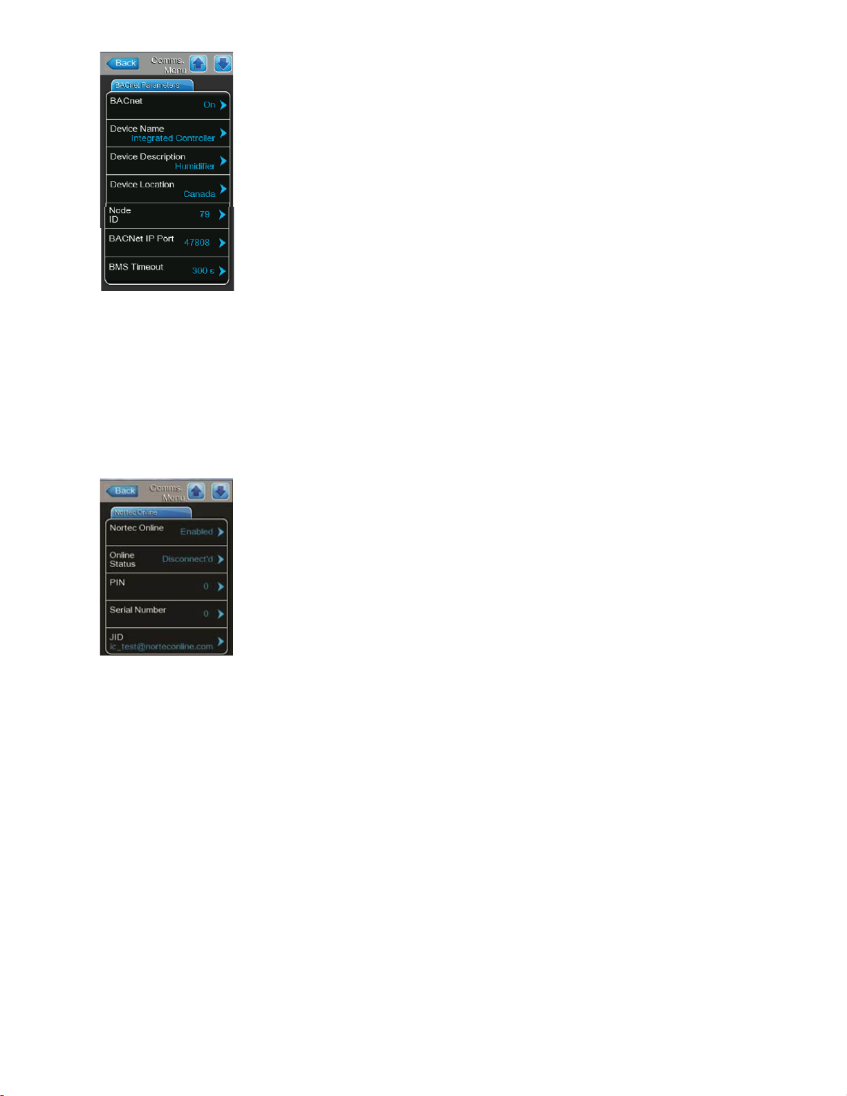
BACnet
MSTP = Use a BACnet MSTP connection. IP = Use a BACnet IP connection.
Off = No BACnet connection. (Default = Off).
Device Name/Description/Location
Used to set a name, description, and location of the humidifier. To enter
letters repeatedly press numeric key until desired letter is displayed (eg
press “2” twice to enter “a”. Press checkmark to save setting.
Node ID
Sets the node ID the humidifier will use on the BACnet network. Select the
desired value using up/down arrows and press checkmark to save.
(Default = 79).
BACnet IP Port
Sets the IP Port the humidifier will use on the BACnet network. Select the desired value using
up/down arrows and press checkmark to save. (Default = 47808).
BMS Timeout
Sets a maximum time the humidifier will wait with no communication from the BACnet network
before a BACnet timeout warning is generated. Exceeding the timeout also stops humidifier
operation if the humidifier Source is set to BACnet in the Controls Menu. (Default = 300s).
Nortec Online:
Enabled: When enabled the humidifier will connect to Nortec Online.
Additional Online parameters are only presented when Nortec Online is
enabled. Default setting Disabled.
Online Status:
Displays the status of Nortec Online either Connected, Disconnected or
Waiting for registration
PIN:
A unique PIN number assigned and written to the humidifier by the Nortec Online server
Serial Number:
Displays the serial number of the humidifier.
JID:
A unique Jabber ID used by the humidifier to communicate with the Online server, including
registration, real time data transfer and historical data downloading.
Maintenance and Servicing | 60
Page 64

Service Submenu
Cylinder A/B Reset
The humidifier uses information about cylinder replacement to optimize
the performance of the humidifier. Only after replacing a cylinder select
Reset Cylinder, and then press the Yes button.
Drain Cylinder
Allows the user to drain the cylinder(s). Select the cylinder(s) that should
be drained and press the checkmark. To interrupt draining press cancel.
Fault / Service History
Displays the fault / service events that have been recorded by the
humidifier.
Reset Fault/Service History
Deletes the list of Faults/Service events stored in the Fault / Service
history. Resetting the fault / service history is not normally required, but
can be done after repairs to remove faults that are no longer needed.
Export History
Allows export of the service history to a USB memory stick plugged into the
humidifier controller USB port. The file can be sent to Nortec for analysis.
Input Diagnostics
Displays a list of the humidifier’s inputs and the current status/value.
Output Diagnostics
Displays a list of the humidifier’s components and remote indication relays. The components
and relays can be activated for diagnostic purposes.
Admin Submenu
Setpoint Password
Yes = The humidifier will prompt a user for a password in order to change
the setpoint from the main status screen. No = allows any user to change
the setpoint from the main status screen without a password. (Default =
Yes)
Main Menu Password
Sets whether a password is required to access the main menu. No =
pressing Menu on the main status screen opens the Main menu without
requesting a password.
Software Update
Initializes a software update from a USB memory stick plugged into the humidifier controller
USB port.
61 | Maintenance and Servicing
Page 65

Maintenance and Servicing
63 Required Maintenance
63 Cylinder Spent Warning / Fault
64 Replacement Cylinder
65 Removing the Cylinder
66 Drain Valve Cleaning
67 Installing the New Cylinder
68 Extended Shutdown
68 Starting After Extended Shutdown
69 NH-EL Maintenance Checklist
Maintenance and Servicing | 62
Page 66

Status LED Yellow
+
Cylinder Spent
=
Cylinder is Spent and
must be replaced.
Fault LED On
+
Cylinder Spent
=
Cylinder is Spent and
must be replaced.
Humidifier has
shut down.
Danger:
serious injury or damage to property.
Required Maintenance
The NH-EL humidifier has been designed to require very little maintenance. Regular
maintenance consists of checking the humidifier to ensure it is in good condition, replacing the
cylinder when the software advises that the cylinder is spent (and changing the o-ring), as well
as cleaning out the drain valve whenever the cylinder is replaced.
Cylinder Spent Warning / Fault
The steam cylinder is disposable and must be replaced at end of cylinder life. Cylinder life is
dependent on water supply conditions and humidifier usage.
Resetting and/or servicing a spent cylinder to extend operation will void warranty and could cause
Warning
When the software
determines that the
cylinder is spent, it first
displays a warning and
turns on the yellow
service LED. The
humidifier will continue
to operate for another
72 hours after the
warning is displayed.
63 | Maintenance and Servicing
Fault
After 72 hours the
humidifier will display a
fault and shut down.
If a replacement
cylinder is not yet
available, the humidifier
can be temporarily put
back into service by
turning the humidifier
off and on. The
humidifier will run for
another 72 hours at
reduced capacity.
Figure 46: Cylinder Spent Warning / Fault
Page 67

Electrode Pin
Connect color coded cylinder
plugs to pin with corresponding
color label. There may be 2, 3
or 6 connections depending on
cylinder.
The spring loaded plug should
fit snugly on the pin. Replace if
loose or any signs of damage.
Steam Outlet
Secure steam hose to
outlet with hose clamp.
Electrode Internal
Mounting Point
High Water Sensor Pin
Has a plastic collar
around it. Connect
orange high water
sensor wire here.
Label
Identifies cylinder type in
top left. Always replace
cylinder with the same
model.
end of life.
Replacement Cylinder
The label on the existing cylinder identifies the cylinder type in its top left corner. When ordering
a cylinder always quote the three or five digit model number on the label, the humidifier’s serial
number and the humidifiers voltage. Serial number and voltage are located on the specification
label on the right side of the humidifier.
Note: Nortec recommends keeping several replacement cylinders in stock throughout the
humidification season. This will prevent possible downtime when the humidifier reports cylinder
Figure 47: NH-EL Cylinder
Maintenance and Servicing | 64
Page 68

Manual Drain Switch
On/Off Switch
Door Screw
Cylinder Plug
Lift vertically
Hose Clamp
Tilt cylinder
forward to clear
hose and then
lift from drain
valve.
Cylinder
SPACE
Warning
Removing the Cylinder
Disconnect main power at the external disconnect before any servicing.
The plumbing and electrical compartments contain high voltage components and
1 Drain the existing cylinder. Press Drain Icon on the display. If asked for a password enter
2 Close supply water shut off valve.
3 Turn the humidifier On/Off switch off.
4 Turn off power to the humidifier with the external disconnect.
wiring. Access should be limited to authorized personnel.
Cylinder may be hot, take care when handling.
0335 and press the checkmark. Either press “Yes” to confirm the cylinder should be
drained or, for a double unit, select which cylinder(s) should be drained and then press
“Yes”. The display will show that the unit is being drained. Let the humidifier drain until no
more water is flowing out to drain. The NH-EL will count down the drain time with a 20
minute timer.
5 Loosen the plumbing door screw and remove the door.
6 Remove the cylinder plugs from the cylinder pins by pulling vertically.
7 Using a flat screwdriver, loosen the hose clamp where the hose is connected to the cylinder.
8 Using a small flat screwdriver, press the tab on the cable tie holding the cylinder in place
9 Tip the top of the cylinder forward to pivot it out of the steam hose. When free of steam
and pull the cable tie open.
hose lift the cylinder out.
65 | Maintenance and Servicing
Figure 48: Cylinder Removal
Page 69

Cylinder Port
and O-ring
Ground Wire
Spade Connectors
Solenoid
Brass Nut
(Actuator)
Hose and
Hose Clamp
Screws
Drain Valve Cleaning
Always clean the drain valve before installing a new cylinder. Scale from the spent cylinder may
have fallen into the drain valve and could prevent its proper operation. To properly clean the
drain valve it must be removed and disassembled.
Note: Be sure to reattach the green ground wire to reduce the risk of electrical shock.
1 Disconnect spade terminals from the drain valve.
2 Remove the screw holding the green ground wire and the two screws holding the valve to
the drain pan.
3 Squeeze the tabs of the spring clamp holding the hose to the drain valve and slide it up the
hose. Pull hose from drain valve. Lift the drain valve from the drain pan.
4 Unsnap red coil cap on solenoid and remove the solenoid from the valve.
5 Loosen brass nut holding actuator to plastic housing with a wrench and disassemble
actuator.
6 Clean actuator components and valve housing (inlet port, outlet port, and cylinder port). Put
new o-ring that was supplied with new cylinder into valve.
7 Reassemble actuator making sure tapered end of spring is oriented as shown in Figure 50:
Drain Valve Actuator Assembly. Tighten brass nut 1/4 turn past hand tight.
8 Clean out end of hose and reattach to valve. Slide hose clamp back in place and place valve
into drain pan.
9 Secure valve with 2 screws and attach green ground wire to solenoid.
Figure 49: Drain Valve
Maintenance and Servicing | 66
Page 70

CAUTION: Make sure the new cylinder is the same model as the one that was removed. Model number
Sleeve
and
Solenoid
Spring
Plunger
(Note Orientation)
NOTE: If the “Cylinder Reset” is not performed the humidifier will operate for 72 hours and then fault
Figure 50: Drain Valve Actuator Assembly
Installing the New Cylinder
1 Insert cylinder into drain valve. Tilt cylinder forward and fit end of steam hose to steam
2 Secure cylinder with the reusable cable tie. Hand tighten hose clamp being careful not to
3 Attach color coded cylinder plugs to the corresponding color coded cylinder pin. Push down
4 Replace the humidifier door and secure with door screw.
5 Turn on power to humidifier with the external disconnect.
6 Open supply water shut off valve.
is on top left corner of cylinder label.
outlet. Tip cylinder back into place.
over tighten and crush the plastic cylinder steam outlet. The Maximum torque is 12 in-lbs
for 7/8”Nortec steam hose and 16 in-lbs for 1 3/4" Nortec steam hose.
completely. Connect high water sensor plug. Spring loaded plugs should fit snuggly onto
the cylinder pin. Replace if they are loose or damaged.
7 Turn the humidifier On/Off switch to On.
8 After the software has completed its start up self check reset the cylinder by pressing in the
cylinder box of the status screen and confirming the cylinder was replaced in the following
screen.
on cylinder spent!
67 | Maintenance and Servicing
Page 71

Note: As long as the NH-EL is powered, it will automatically drain the cylinder when
Extended Shutdown
Should it be required to disconnect power to the humidifier for a period of extended shut-down,
always drain the cylinder first.
1 Utilize the Drain Cylinder function on page 61
2 Wait until the humidifier is completely drained (20 minutes).
3 Turn the On/Off switch to the Off position.
4 Shut off power to the humidifier with the external disconnect.
5 Close the supply water shut-off valve.
there has not been a call for humidity for an extended period of time. This feature will
reduce or prevent the possibility of corrosion of the electrodes and the accumulation of
algae and bacteria growing in the cylinder. The cylinder will remain empty until there is
a call for humidity at which time the fill valve will open and refill the cylinder. The unit
will go through its normal process for optimum operation.
Starting After Extended Shutdown
1 Check to see the humidifier has not been damaged and the installation has not been
altered. Refer to the Chapter on Start Up.
2 Turn on the power to the humidifier with the external disconnect.
3 Turn the On/Off switch to the On position.
4 Drain the humidifier completely by pressing and releasing the manual drain button. Wait
until there is no water flowing to drain. It usually takes less than 10 minutes.
5 Follow the start up procedure in the chapter on Start Up.
Maintenance and Servicing | 68
Page 72

NH-EL Maintenance Checklist
Model #: _________________
Serial #: _________________ Tag: ________
Cylinder #:
Cylinder / System Check
Warning Cylinder Spent Fault Cylinder Spent
(If software displays Warning Cylinder Spent then cylinder must be replaced)
Yellow LED On with Max Level Warning.
(If Yellow LED is On with Max Level Warning and cylinder is not new, cylinder may have to be replaced soon.)
Other warnings or Faults shown in display? No Yes
(See Troubleshooting Chapter for actions to address warnings and faults if present)
Replace Cylinder
Cylinder drained.
Disconnect open, On/Off switch to Off, water shut off valve closed, door removed.
Cylinder removed
Drain valve removed / cleaned / new O-Ring
Drain valve installed / ground wire attached.
New Cylinder Installed and hose clamps tight (12 in-lbs for 7/8” steam hose and 16 in-lbs
for 1 ¾” steam hose). New cylinder model #
(Should be same as removed cylinder)
Cylinder plug colors match cylinder dots.
Cylinder plugs snug and in good condition.
High Water Sensor plug snug and in good condition.
Electrical wiring not loose and in good condition.
Steam hoses and steam lines in good condition / No kinks in hose.
No Signs of water leaking around humidifier, steam line, condensate returns.
Door replaced, water shut off valve opened, On/Off switch to On, Disconnect Closed.
“Reset Cylinder” in Software, (press cylinder status, Password 0335).
Inspected by: Date of inspection: _______/_______/______
Company:
69 | Maintenance and Servicing
Page 73

Troubleshooting
71 Organization of Troubleshooting Chapter
71 Troubleshooting Requirements
72 General Troubleshooting
72 Humidifier
73 Steam Distributors
74 SAM-e
74 Blower Pack
74 Digital Humidistat
75 NH-EL Warnings and Faults
75 Warnings
75 Faults
75 Clearing a Fault
81 NH-EL Wiring Diagram (Cylinder A)
82 NH-EL Wiring Diagram (Cylinder B)
Troubleshooting | 70
Page 74

CAUTION: Be aware, when troubleshooting, that the humidifier is powered by high voltage.
NOTE: Most humidifier faults are not caused by faulty equipment but rather by improper
Organization of Troubleshooting Chapter
The troubleshooting chapter is broken down into 2 sections.
General Troubleshooting Deals with troubleshooting incorrect humidifier operation,
steam line and plumbing issues without any control
software warnings or faults.
Humidifier Warnings and Faults Deals with warning and error messages that are generated
by the humidifier’s control software.
Troubleshooting Requirements
Ensure the installation meets the installation requirements outlined in the Installation
Chapter of this manual.
Familiarize yourself with the operation of the humidifier by reading the Operation Chapter of
this manual.
Wiring diagram specific for your humidifier is installed on the inside of the humidifier door. A
generic copy of the NH-EL wiring diagram is also included at the end of this chapter for
reference purposes.
When contacting your local representative or NORTEC for troubleshooting assistance, please
ensure the serial number has been obtained for reference purposes.
Familiarity with both good practices and wiring of the humidifier is recommended. Any
troubleshooting that requires opening the cabinet should be done by qualified personnel.
installation. A complete fault diagnosis always involves a thorough examination of the
entire system. Often, the steam hose connection has not been properly executed, or the
fault lies with the humidity control system.
71 | Troubleshooting
Page 75

Symptom
Cause
Corrective Action(s)
Nothing happens when
On/Off switch is turned On.
1 Fuse blown
1 Check inline fuse in yellow housing
between transformer and driver board.
Check and replace fuses (F2 and F3) on
driver board.
2 Incorrect or no Voltage
2a Check voltage against spec label and
correct.
2b Check disconnect and ensure humidifier
is getting power.
3 Step Down Transformer not
outputting 24VAC
3a Replace the transformer.
3b Verify primary wiring.
4 Door interlock switch open
4a Replace the door
4b Pull door interlock switch out to
override.
Caution! The electrical and plumbing
compartment contains high voltage
components and wiring.
Humidifier will not humidify
or not reaching RH setpoint
1 Security loop open
1a Check if “Security loop”: “Security loop”
is displayed on the humidifier’s display.
1b Check if there is 24 VAC at terminal 2.
1c Check wiring and operation of On/Off
devices connected to terminal 1 and 2.
Ensure they are closing when they should
be.
2 High limit limiting output
2 Check if the high limit is installed too
close to the humidifier, and if it is
operating correctly.
3 No signal on Channel 1
3 Check voltage between terminal 3 and 4.
For demand configuration 27% of full
scale signal must be present for
humidifier to start. For transducer
configuration the signal must be lower
than setpoint for the humidifier to start.
4 No signal on Channel 2
(For units configured for dual
channel operation).
4 Check voltage between terminal 5 and 3.
For demand configuration 27% of full
scale signal must be present for
humidifier to operate. For transducer
configuration the signal must be lower
than setpoint for the humidifier to start.
General Troubleshooting
The following section provides general guidelines for troubleshooting the NH-EL humidifier and
auxiliary components. For detailed troubleshooting information refer to the manuals that were
provided with the auxiliary equipment and to Table 11: Troubleshooting Warnings and Faults
later in this chapter.
Humidifier
Table 10: General Troubleshooting
Troubleshooting | 72
Page 76

Symptom
Cause
Corrective Action(s)
5 Capacity has been manually
limited
5 Check Manual Capacity on status
screens. Adjust “Manual Capacity (A/B)”
under “0335” / ”Configuration” /
”Features” / if necessary.
6 Low conductivity water
6 Check if “Max Level”: “Max Level” is
displayed on the humidifier’s display. If
operated on low conductivity water it may
take several hours for the NH-EL to reach
full output capacity. This is normal.
During this time the humidifier will not
perform any drains and the conductivity
of the water in the cylinder will increase.
Humidifier has faulted or
has a warning
1 Software has detected an
abnormal condition
1 Refer to Table 11: Troubleshooting
Warnings and Faults.
Symptom
Cause
Corrective Action(s)
Distributor spitting out water
1 Distributor not level
1 Use support at end of distributor to
ensure it is level.
2 “P” Trap too close to distributor
2 “P” Trap must be a minimum of 12 in
(30 cm) below the distributor to
ensure flow. Relocate if required.
3 Condensate line not sloped
sufficiently
3 Sufficient slope to ensure flow is
required. Reinstall if required.
4 Trap blocked
4 Check that water flows through trap.
Clear out if blocked.
5 Condensate line double trapped
5 Condensate lines must not have two
traps in sequence. This can cause an
air lock and prevent water draining.
6 Steam line not insulated
6 If steam line is long, condensate build
up could overload distributor
condensate port. Insulate line to
improve efficiency and install
additional condensate traps as
required.
Condensation in duct
1 Installation clearances not
observed
1 Refer to distributor installation manual
for required clearances. Relocate
distributor if required.
2 Design conditions changed
2 Check supply air temperature and
humidity to determine if conditions
have changed.
3 High limit not functioning
3 Check setting and operation of high
limit. Replace if defective.
4 Air proving not installed or not
working
4 Check that the humidifier will only
operate when there is air moving in
the duct.
5 Improper location of high limit
5 Check that high limit is installed where
it can detect high duct humidity.
Steam Distributors
73 | Troubleshooting
Page 77

Symptom
Cause
Corrective Action(s)
SAM-e spitting out water
1 “P” Trap too close to SAM-e
1 “P” trap must be at least 12 in (30
cm) below header. Relocate if
required.
2 Condensate line not sloped
sufficiently
2 Ensure line is sloped sufficiently to
carry condensate produced.
3 Steam line not insulated
3 If steam line is long condensate build
up could overload the SAM-e
condensate port. Insulate the steam
line to improve efficiency and install
condensate traps as required.
SAM-e Grommet leaks
1 Distributor tubes not seated
properly
1 Push distributor tubes down until
support washer is resting on rubber
grommet.
2 Grommet Damaged
2 Replace any damaged grommets
Symptom
Cause
Corrective Action(s)
Blower not operating
Note: Blower pack does not
come on unless steam is
being produced by the
humidifier.
1 No power to blower pack
1a Check power connection.
1b Check blower pack fuses
2 On/Off Thermostat not closing
2 Check wiring to thermostat replace if
it does not close when it is exposed to
steam.
Symptom
Cause
Corrective Action(s)
Humidistat Reading incorrectly
1 Sensor out of calibration
1 See humidistat manual.
2 Improper sensor location
2 Check that the humidistat is
positioned in a location
representative of room humidity.
3 Exposed to draft or heat source
3 Check that heat/cold fluctuations,
drafts, sunlight, doors, or vents are
affecting the reading.
4 No vapour barrier
4 Ensure drafts cannot affect reading
by ensuing vapour barrier is in place
and working.
SAM-e
Blower Pack
Digital Humidistat
Troubleshooting | 74
Page 78

Press on Warning
to get list of warnings/
faults.
Press on any item
in the list to get
detailed info about it.
NH-EL Warnings and Faults
The self-diagnostic system built into the NH-EL is continually monitoring the operation of the
humidifier. When the display shows a warning or fault condition you can find out more
information about the fault by pressing on the warning/fault box. This will display a screen
listing any warnings/faults that are in effect. Pressing on any item in the list will provide a
description as well as causes and possible corrective actions.
Figure 51: Displaying Warning / Fault Information
Warnings
When problem symptoms are detected, the NH-EL will attempt to take self-corrective actions
to try to correct the problem. A warning is displayed on the screen for information purposes
and the humidifier continues to operate.
If the condition which generated the warning is eliminated the warning is cleared from the
display.
While a warning is displayed the status LED is Yellow.
Faults
If the humidifier is not able to self-correct a problem symptom it will, if necessary, respond
by shutting down.
When this occurs, the humidifier illuminates the red “Fault” LED, shuts off power to the
cylinder, and drains the cylinder.
Clearing a Fault
Check the fault message that the humidifier is displaying and take any necessary actions to
correct the cause(s) as outlined in Table 11: Troubleshooting Warnings and Faults.
Power cycle the humidifier with the On/Off switch waiting 3 seconds between turning it off
and on.
75 | Troubleshooting
Page 79

Display Message
LED
System
Detected
Cause
Corrective Action(s)
BMS
BACnet
Nortec Online
Staged
Modulation
Warning/Fault
Red
No Modbus/
BACnet / Nortec
Online / Multi
Mode signal
1 Loose connection
1 Check connections and
polarity of wires.
2 Incorrect
Modbus/BACnet/IP
address or
configuration.
2 Check that address of
humidifier matches that
of network.
3 Humidifier configured
but not connected to
network
3 Configure controls
correctly in “Control
Setting” level of
software (see Operation
Chapter).
4 Improper wire used
4 Use 120 Ohm
impedance shielded
twisted pair cable for
Modbus, Cat 5 for
BACnet IP/ IP.
5 Noise preventing
humidifier from
detecting signal.
5 Eliminate source of
noise causing
interference.
Control Signal
Warning / Fault
No signal from
RH control
sensor
No signal from
RH Limit sensor
1 Sensor not powered
1 Use multimeter to
check that sensor is
powered.
2 Sensor not wired
correctly
2 Check wiring is secure
and wired correctly per
instructions in
installation chapter.
3 Defective sensor
3 Check if sensor output
is corresponding to RH.
If not replace the
sensor.
Red
4 RH less than 5%
4 RH less than 5% are
interpreted as a broken
sensor. Contact
NORTEC Representative
for recommendation.
Red
5 Humidifier control
configuration incorrect
5 Check that the
humidifier control
configuration matches
the installed sensor
output.
Current Off Fault
Red
Current detected
with no demand
1 Contactor seized closed
1 Open Disconnect, check
if contactor is closed
2 Driver Board out of
Calibration
2 If display indicates
output with contactor
open, then replace the
driver board.
Table 11: Troubleshooting Warnings and Faults
Troubleshooting | 76
Page 80

Display Message
LED
System
Detected
Cause
Corrective Action(s)
Cylinder Spent
Yel
Red
Electrodes
covered with
scale.
1 Cylinder electrodes are
covered with scale and
humidifier cannot meet
demand
1 Replace cylinder with
same model number
(see maintenance
chapter)
Excess Current
Warning/Fault
Yel
Current has
exceeded 130%
of max Full Load
Amps
5 Water supply too
conductive
5a Contact Nortec
representative for
recommendation on
alternate cylinder
5b Change the water
supply
Red
6 Wrong cylinder installed
6 Install correct cylinder
model
7 Cylinder Spent but not
detected by software
7 Replace the cylinder
(see maintenance
chapter)
Fill Timeout
Warning / Fault
Fill valve
activated for long
time, but high
water level not
reached.
Water level in
cylinder should
rise faster than
1” per minute.
1 Drain valve leaking or
stuck open
1 Clean drain valve or
replace (see
maintenance chapter)
2 Water shut off valve
closed
2 Open shut off valve
3 Fill Valve strainer
blocked
3 Clean out strainer on fill
valve inlet.
Red
4 High system back
pressure
4a Check for kinked hose
4b Check for proper
condensate removal
(see installation
chapter)
4c Install fill cup
extension
5 Air flow into cylinder
through steam line
5 Disconnect steam line,
let cylinder fill part way,
then reconnect steam
line.
Foaming Cylinder
Warning / Fault
Red
Foam inside the
cylinder.
1 Back pressure
restricting water from
entering cylinder
1a Check for restrictions
and proper condensate
removal in steam line.
1b If water is going down
drain during fill cycle
then install fill cup
extension kit.
2 Organic material in
water
2 Install filter to remove
organic material
3 Drain blocked water
over concentrated
3 Clean the drain line
77 | Troubleshooting
Page 81

Display Message
LED
System
Detected
Cause
Corrective Action(s)
Foaming Cylinder
Warning / Fault
Red
4 Humidifier short cycling
4 Observe operation to
ensure humidifier can
normally run long
enough to perform a
drain. If not turn on the
Short Cycle feature on
page 56.
Low Conductivity
Warning
Low water
conductivity
1 Drain valve leaking
1 Clean drain valve or
replace (see
maintenance chapter)
2 Back pressure causing
some fill water to go
down drain
2a Check for restrictions
and proper condensate
removal in steam line.
2b If water is going down
drain during fill cycle
then install fill cup
extension kit.
3 Wrong Cylinder Installed
3 Install cylinder of same
model number as was
previously installed
4 Newly installed cylinder
not reaching demand
for extended time due
to Low water
conductivity
4a Add 1/4 teaspoon of
salt to fill cup.
4b Adjust drain factor to
0.7 in User Defined
Settings (see operation
chapter)
4c Turn on the Low
Conductivity feature on
page 56.
Max Level Warning
Water level at
top of cylinder or
foaming
1 Humidifier has filled to
top of cylinder without
reaching demand
1 None, for information
only, it is normal for a
new cylinder to reach
max level before water
in cylinder is
concentrated and for an
old cylinder to reach
max level near the end
of cylinder life.
1b If the cylinder is new,
add ¼ teaspoon of salt
to fill cup to assist
cylinder in
concentrating.
1c Supply water
conductivity too low (DI
or RO). Change to
potable water supply
with conductivity above
150 µS/cm.
Troubleshooting | 78
Page 82

Display Message
LED
System
Detected
Cause
Corrective Action(s)
2 Water foaming
2 Check if water level is at
top of cylinder. If water
is not at top there may
be foam in the cylinder.
Consider the Foam
Mode feature on page
55.
No Current Fault
Red
Water level at
top of cylinder
with no current
1 Current transformer
loose on driver board
1 Open disconnect,
ensure current
transformer spade
connectors are secure.
Squeeze with pliers if
loose.
2 Primary wire not looped
through current
transformer.
2 Open disconnect, rewire
primary wire through
current transformer.
3 High water sensor plug
is on an electrode pin.
3 Install high water sensor
plug on cylinder pin with
shroud around it.
Remote Disabled
Warning
Network
shutdown
message
1 Network signal received
by humidifier to shut
down.
1 Normal operation for
humidifier on network
control. Contact network
administrator to enable
humidifier.
RH High Warning
RH higher than
high RH setpoint
1 Setpoint higher than RH
alarm setting
1 If the humidifier is still
operating then check
and adjust setpoints.
RH Low Warning
RH Lower than
low RH setpoint
1 Humidifier not running
1 Check why humidifier is
not running and put it
into operation.
2 Setpoint lower than RH
low alarm setting
2 Check and adjust
setpoints.
Safety Loop Open
Grn
Blink
Security loop
open (terminal 1
and 2)
1 On/Off device
connected to security
loop is open
1a Normal operation, no
action required
1b Wrong setpoint, A/P
not sensing air
movement
2 Loose wire
2 Check wiring to all
On/Off devices
connected to terminals
1 and 2.
SIM Card Fault
Red
Controller cannot
detect a valid
SIM card
1 Improper SIM card
installation or missing
1 Check that SIM card is
installed and socket
closed.
2 Incorrect SIM card
2 Check that the SIM card
serial number matches
the humidifier’s.
79 | Troubleshooting
Page 83

Display Message
LED
System
Detected
Cause
Corrective Action(s)
Staged
Modulation
Warning
Red
Slave unit not
communicating
with Master Unit.
1 Master unit not
configured correctly
1 Check configuration of
master as outlined in
Multi Mode
Configuration
2 Slave unit not
configured correctly
2 Check configuration of
slave as outlined in
Multi Mode
Configuration
3 Wiring to master unit
disconnected
3 Check that wire
connected to J10 of
Master and Slave and
that polarity is not
reversed
4 Incorrect wire type used
4 Use 18-24 AWG multi-
strand, twisted pair,
shielded cable
Unstable Control
Warning
Demand
swinging from
low to high
rapidly
1 Improper Proportional
and Integral settings in
control
1 Adjust proportional and
integral settings to
reduce swings in
demand signal.
2 Control humidistat
installed too close to
diffuser or doorway to
un-humidified space
2 Install humidistat so
that it senses air
representative of space
being humidified.
3 Defective control
3 Replace defective
control
Troubleshooting | 80
Page 84

NH-EL Wiring Diagram (Cylinder A)
Built On
Blower Pack
Primary Power
External
Cylinder
B
Diagram
(2569829)
Internal
A
B
C
D
{
E
F
L1
L2L3
Fuse 1 Amp
(if Required)
S
S
Transformer
(if required)
PRI
120V
S
S
Fuse 1.5 A
(if required)
Circuit for Cylinder A
Blower Pack
Air Proving
Security
1 2
Loop
3
B
(-) Signals
4
br
(+) Control Signal
GND
+ 10 Vdc
(+) Limit Signal
+
5
7
6
bl
B
RR
N.O.
8 9
G
OPTIONAL
Fault Remote PCB
NC
NC
NO
NO
COM
COM
Steam
Service
Unit ON
W
NO
NO
COM
COM
Error
Optional Fuses
Contactor
Contactor
Fill V
Drain V
Fill V
Optional for
drain water
cooling
or
or
W
or
or
R
B
R
B
G
PRI
SEC
CONTACTOR
RR
INLET
S
W
BB
W
DRAIN
3.0 A (005-100)
4.0 A (150-200)
Door Interlock
Switch
Cyl. B
Cyl. A
G
R
B
Aux. Drain
LEV. SENSOR
SL
24
SL
24
24Vac
POWER SUPPLY
GND
ON/OFF
Switch
3
1
Switch
4
R
R
2
For cylinder A identification
DIP switch 1 and 2 must be
in the OFF position
ONON
J3
J2
J1
J6
Master/Slave
J10
R
B
R
B
Port
J12
J14
J15
J16
Cylinder
2,3, and 6 electrode
F1
CURRENT SENS
IN
24V
BLOWER
GND
LIMIT
IN
GND
IN
10V
. ..
CONTROL
V+
W
G
B
bl
br
R
High
Water
Plug
NH-EL SERIES HUMIDIFIER (Cylinder A)
WIRING DIAGRAM
DIAGRAM No. 2569828 REV. E Date: July 4, 2014.
Figure 52: Wiring Diagram for NH-EL (Cylinder A)
J19
J23
U
J21
U
U
U
Page 85

NH-EL Wiring Diagram (Cylinder B)
External
Internal
Circuit for Cylinder B
Blower Pack
Air Proving
Security
1 2
R
Loop
B
(-) Signals
3
B
(+) Control Signal
4
br
+ 10 Vdc
(+) Limit Signal
+
GND
5
7
6
bl
B
R
N.O.
8 9
G
W
External
Internal
A
B
C
D
E
F
}
Cylinder
A
Diagram
(2569829)
Optional Fuses
Cylinder
2,3, and 6 electrode
Contactor
Contactor
Fill V
Drain V
Fill V
Optional for
drain water
cooling
High
Water
Plug
R
B
R
B
W
G
For cylinder B identification
DIP switch 1 and 2 must be
W
in the ON position
ONON
or
or
BB
RR
W
Contactor Inlet Drain
F1
G
Current Sens
LEV
. SENSOR
SL
24
SL
B
R
24
24Vac
R
POWER SUPPLY
B
GND
IN
W
G
24V
BLOWER
GND
LIMIT
10V
. ..
CONTROL
B
bl
IN
GND
IN
br
V+
R
NH-EL SERIES HUMIDIFIER (Cylinder B)
WIRING DIAGRAM
DIAGRAM No. 2569829 REV. D Date: Jul 4, 2014
Figure 53: Wiring Diagram for NH-EL (Cylinder B)
Page 86

Spare Parts
84 NH-EL Plumbing Parts
88 NH-EL Electrical Parts
92 Blower Pack Parts
95 Warranty
Part Ordering
The following illustrations and tables list the most commonly used NH-EL parts.
First locate the part you require in the illustration corresponding to your NH-EL unit.
Find the item number in the first column of the table adjacent to the illustration.
Read across the table to the column which corresponds to the number of phases, voltage
and capacity of your unit.
To order parts, or help in identifying the part you need, contact your local Nortec agent.
83 | Spare Parts
Page 87

NH-EL Plumbing Parts
Figure 54: NH-EL Plumbing Parts
Spare Parts| 84
Page 88

MODEL 5
Volts/Ph
NORTEC
PART NO.
110-120
208/1
220-240/1
277/1
380/1
440-480/1
550-600/1
208/1
220-240/1
277/1
380/1
440-481/1
550-600/1
208/3
220-240/3
380/3
440-480/3
550-600/3
208/3
220-240/3
380/3
440-480/3
550-600/3
CYLINDER 202
1519002 1 1 1 1
CYLINDER 203
1519003 1
CYLINDER 204
1519004 1 1
CYLINDER 321
1519020 1 1 1
CYLINDER 305
1519025 1
CYLINDER 309
1519029 1 1
CYLINDER 311
1519031 1 1 1
CYLINDER 303
1519023 1 1
CYLINDER 421
1519040 1 1
CYLINDER 407
1519047 1 1
CYLINDER 411
1519051 1 1
2
DRAIN CHANNEL
2573514 1 1 1 1 1 1 1 1 1 1 1 1 1 1 1 1 1 1 1 1 1 1 1
3
VALVE DRAIN + 24V COIL
1456000 1 1 1 1 1 1 1 1 1 1 1 1 1 1 1 1 1 1 1 1 1 1 1
4
FILL CUP ASSEMBLY, SM
2574143 1 1 1 1 1 1 1 1 1 1 1 1 1 1 1 1 1 1 1 1 1 1 1
5
SMALL STEAM LINE 0.875
IN. ID IN.
2574131 12 12 12 12 12 12 12 12 12 12 12 12 12 12 12 12 12 12 12 12 12 12 12
VALVE, SINGLE FILL, 0.5
L/min
2573515 1 1 1 1 1 1 1 1 1 1 1 1 1 1 1 1 1 1
VALVE, SINGLE FILL, 1.2
L/min
2573522 1 1 1 1 1
VALVE, DUAL FILL, 3.3
L/min, 0.5 L/min
2574133 1 1 1 1 1 1 1 1 1 1 1 1 1 1 1 1 1
VALVE, DUAL FILL, 3.3
L/min, 1.2 L/min
2574134 1 1 1 1 1
7
FITTING BRASS 3/4 BSP /
WASHER = 1/2" NPT
2574137 1 1 1 1 1 1 1 1 1 1 1 1 1 1 1 1 1 1 1 1 1 1 1
8
CABLE TIE REUSABLE 1400 CYL SZ X2
2574138 1 1 1 1 1 1 1 1 1 1 1 1 1 1 1 1 1 1 1 1 1 1 1
CYLINDER PLUG KIT, QTY 2
2577737 1 1 1 1 1 1 1 1 1 1 1 1
SUPER PLUG KIT, R-B, NHEL
2574140 1
CYLINDER PLUG KIT, QTY 3
2573529 1 1 1 1 1 1 1 1 1 1
10
HIGH WATER SENSOR
PLUG
2577738 1 1 1 1 1 1 1 1 1 1 1 1 1 1 1 1 1 1 1 1 1 1 1
OPTIONAL COMPONENTS
FOAM DETECTION OPTION
FOAM DETECTION KIT
SMALL
2574091 1 1 1 1 1 1 1 1 1 1 1 1 1 1 1 1 1 1 1 1 1 1 1
-WITH BUILT ON BLOWER
PACK
2574093 1 1 1 1 1 1 1 1 1 1 1 1 1 1 1 1 1 1 1 1 1 1 1
FILL CUP EXTENSION
FILL CUP EXTENSION KIT
2574073 1 1 1 1 1 1 1 1 1 1 1 1 1 1 1 1 1 1 1 1 1 1 1
DRAIN WATER COOLING
3.3 L/min, 0.5 L/min
2574079 1 1 1 1 1 1 1 1 1 1 1 1 1 1 1 1 1 1
3.3 L/min, 1.2 L/min
2574081 1 1 1 1 1
*Optional Components
N/S - Not Shown
1
6
6*
9
Not Shown Optional
Components
ITEM
NO.
DESCRIPTION
SINGLE PHASE
THREE PHASE
102020
30
Table 12: NH-EL 005-30 Plumbing Parts List
85 | Spare Parts
Page 89

Figure 55: NH-EL Plumbing Parts
NH-EL Plumbing Parts
Spare Parts| 86
Page 90

Table 13: NH-EL 050-200 Plumbing Parts List
MODEL
Volts/Ph
NORTEC
PART NO.
208/3
220-240/3
380/3
440-480/3
550-600/3
208/3
220-240/3
380/3
440-480/3
550-600/3
208/3
220-240/3
380/3
440-480/3
550-600/3
208/3
220-240/3
380/3
440-480/3
550-600/3
208/3
220-240/3
380/3
440-480/3
550-600/3
CYLINDER 621
1519080 1 1 1 1 1 1 2 2 2 2
CYLINDER 605
1519085 1 1 1 1 1 1 2 2 2 2
CYLINDER 603
1519083 1 1
2
DRAIN CHANNEL
2573514 1 1 1 1 1 1 1 1 1 1 1 1 1 1 1 2 2 2 2 2 2 2 2 2 2
3
VALVE DRAIN + 24V
COIL
1456000 1 1 1 1 1 1 1 1 1 1 1 1 1 1 1 2 2 2 2 2 2 2 2 2 2
4
FILL CUP
ASSEMBLY LARGE
2574142 1 1 1 1 1 1 1 1 1 1 1 1 1 1 1 2 2 2 2 2 2 2 2 2 2
5
LARGE STEAM LINE
1.750 IN. ID IN.
2574132 12 12 12 12 12 12 12 12 12 12 12 12 12 12 12 24 24 24 24 24 24 24 24 24 24
VALVE, SINGLE
FILL, 2.0 L/min
2573523 1 1 1 1 1 1 1 1 1 1 2 2 2 2 2
VALVE, SINGLE
FILL, 3.3L/min
2573524 1 1 1 1 1 2 2 2 2 2
VALVE, DUAL FILL,
3.3 L/min, 2.0 L/min
2574135 1 1 1 1 1 1 1 1 1 1 2 2 2 2 2
VALVE, DUAL FILL,
3.3 L/min, 3.3L/min
2574136 1 1 1 1 1 2 2 2 2 2
7
FITTING BRASS 3/4
BSP / WASHER 1/2" NPT
2574137 1 1 1 1 1 1 1 1 1 1 1 1 1 1 1 2 2 2 2 2 2 2 2 2 2
8
CABLE TIE
REUSABLE 5-600
CYL SZ X2
2574139 1 1 1 1 1 1 1 1 1 1 1 1 1 1 1 2 2 2 2 2 2 2 2 2 2
CYLINDER PLUG
KIT, QTY 3
2573529 2 2 2 2 2 2 2 2 2 4 4 4 4
SUPER PLUG KIT, RY-B, NH-EL
2574141 2
2
2 2 2 2 4 4 4 4 4 4
10
HIGH WATER
SENSOR PLUG
2577738 1 1 1 1 1 1 1 1 1 1 1 1 1 1 1 2 2 2 2 2 2 2 2 2 2
OPTIONAL COMPONENTS
FOAM DETECTION
FOAM DETECTION
KIT MEDIUM
2574095 1 1 1 1 1 1 1 1 1 1 1 1 1 1 1
FOAM DETECTION
KIT LARGE
2574099 1 1 1 1 1 1 1 1 1 1
FILL CUP
EXTENSION
FILLCUP
EXTENSION KIT
NHTC/NHPC
2574073 1 1 1 1 1 1 1 1 1 1 1 1 1 1 1 2 2 2 2 2 2 2 2 2 2
DRAIN WATER
COOLING
3.3 L/min, 2.0 L/min
2574083 1 1 1 1 1 1 1 1 1 1 2 2 2 2 2
3.3 L/min, 3.3L/min
2574085 1 1 1 1 1 2 2 2 2 2
*Optional Components
N/S - Not Shown
** For far tank on double units
DESCRIPTION
THREE PHASE
5075100
150
200
1
6
6*
9
Not Shown Optional Components
ITEM
NO.
87 | Spare Parts
Page 91

NH-EL Electrical Parts
Figure 56: NH-EL Electrical Parts
Spare Parts| 88
Page 92

Table 14: NH-EL 005-030 Electrical Parts List
MODEL 5
Volts/Ph
NORTEC
PART NO.
110-120
208/1
220-240/1
277/1
380/1
440-480/1
550-600/1
208/1
220-240/1
277/1
380/1
440-481/1
550-600/1
208/3
220-240/3
380/3
440-480/3
550-600/3
208/3
220-240/3
380/3
440-480/3
550-600/3
CONTACTOR 30 AMP 1PH
2574148 1 1 1 1 1 1 1 1 1 1
CONTACTOR 30 AMP 3PH
2574149 1 1 1 1 1 1 1 1
CONTACTOR 40 AMP 3PH
2574150 1 1 1 1
CONTACTOR 50 AMP 3PH
2574151 1
TERMINAL BLOCK 2 POLE
95A
2574153 1 1 1 1 1 1 1 1 1 1 1 1 1
TERMINAL BLOCK 3 POLE 95
AMP
2574154 1 1 1 1 1 1 1 1 1 1
3
GROUND CLAMP (SMALL)
2574158 1 1 1 1 1 1 1 1 1 1 1 1 1 1 1 1 1 1 1 1 1 1 1
TRANSFORMER 120/24 VAC
75 VA
2574159 1
TRANSFORMER 208 24V
75VA
2574160 1 1 1 1
TRANSFORMER 240/24 VAC
75 VA
2574161 1 1 1 1
TRANSFORMER 277/24V
75VA
2574162 1 1
TRANSFORMER 380/24V
75VA
2574163 1 1 1 1
TRANSFORMER 480/24 VAC
75 VA
2574164 1 1 1 1
TRANSFORMER 600/24 VAC
75 VA
2574165 1 1 1 1
5
PCB FAULT REMOTE
(OPTIONAL)
2574171 1 1 1 1 1 1 1 1 1 1 1 1 1 1 1 1 1 1 1 1 1 1 1
IC ASSEMBLY, NH-EL + SIM
2576572 1 1 1 1 1 1 1 1 1 1 1 1 1 1 1 1 1 1 1 1 1 1 1
IC ASSEMBLY, NH-EL
2570436 1 1 1 1 1 1 1 1 1 1 1 1 1 1 1 1 1 1 1 1 1 1 1
7
DRIVER BOARD, NH-EL
2570437 1 1 1 1 1 1 1 1 1 1 1 1 1 1 1 1 1 1 1 1 1 1
8
SWITCH, PUSH ON/OFF
2569654 1 1 1 1 1 1 1 1 1 1 1 1 1 1 1 1 1 1 1 1 1 1 1
9
SWITCH SPST 208-240V
1473010 1 1 1 1 1 1 1 1 1 1 1 1 1 1 1 1 1 1 1 1 1 1 1
10
SWITCH INTERLOCK IDM 423 1323091 1 1 1 1 1 1 1 1 1 1 1 1 1 1 1 1 1 1 1 1 1 1 1
FUSE 3 AMP 2523523
1 1 1 1 1 1 1 1 1 1 1 1 1 1 1 1 1 1 1 1 1 1 1
CABLE, RIBBON 10 PIN, NHEL DRIVER BOARD
2574173 1 1 1 1 1 1 1 1 1 1 1 1 1 1 1 1 1 1 1 1 1 1 1
CABLE RIBBON 10 PIN NHTC
FAULT
2574174 1 1 1 1 1 1 1 1 1 1 1 1 1 1 1 1 1 1 1 1 1 1 1
TRANSFORMER 208, 240V
TO 120V 150 VA
2571460 1 1 1 1 1 1 1 1
TRANSFORMER 277, 380V
TO 120V 150VA
2571461 1 1 1 1 1 1
TRANSFORMER 480, 600V
TO 120V 150 VA
2571462 1 1 1 1 1 1 1 1
PRIMARY FUSE JJN50
(JLLN50)
1509692 2
PRIMARY FUSE JJN40
(JLLN40)
1423173 2 2 2 2 2 2 3 3 3 3
PRIMARY FUSE JJS40
(JLLS40)
1423160 2 2 2 2 2 2 3 3 3 3 3 3
ITEM
NO.
DESCRIPTION
SINGLE PHASE
THREE PHASE
102020
30
OPTIONAL
COMPONENTS
1
2
4
6
NOT SHOWN
NOT SHOWN,
SPACE MODELS
ONLY
89 | Spare Parts
Page 93

NH-EL Electrical Parts
Figure 57: NH-EL Electrical Parts
Spare Parts| 90
Page 94

MODEL
Volts/Ph
NORTEC
PART NO.
208/3
220-240/3
380/3
440-480/3
550-600/3
208/3
220-240/3
380/3
440-480/3
550-600/3
208/3
220-240/3
380/3
440-480/3
550-600/3
208/3
220-240/3
380/3
440-480/3
550-600/3
208/3
220-240/3
380/3
440-480/3
550-600/3
CONTACTOR 30 AMP 3PH
2574149 2 2 1 1 2 2 4 4
CONTACTOR 40 AMP 3PH
2574150 2 1 2 2 4
CONTACTOR 50 AMP 3PH
2574151 2 2 1 1 4 4 2 2
CONTACTOR 62 AMP 3PH
2574152 2 2 1 4 4
TERMINAL BLOCK 3 POLE 95 AMP
2574154 1 1 1 1 1 1 1 1 1 1 1 1 1 1
TERMINAL BLOCK 3 POLE 150 AMP
2574155 1 1 1 1 1 1 1 1
TERM. BLOCK 3 POLE 310 AMP
2574156 1 1 1
GROUND CLAMP (SMALL)
2574158 1 1 1 1 1 1 1 1 1
GROUND CLAMP (LARGE)
2574370 1 1 1 1 1 1 1 1 1 1 1 1 1 1 1 1
TRANSFORMER 208 24V 75VA
2574160 1 1 1
TRANSFORMER 240/24 VAC 75 VA
2574161 1 1 1
TRANSFORMER 380/24V 75VA
2574163 1 1 1
TRANSFORMER 480/24 VAC 75 VA
2574164 1 1 1
TRANSFORMER 600/24 VAC 75 VA
2574165 1 1 1
TX 24VAC 150VA, PRIMARY 208
2574166 1 1
TX 24VAC 150VA, PRIMARY 240
2574167 1 1
TX 24VAC 150VA, PRIMARY 480
2574168 1 1
TX 24VAC 150VA, PRIMARY 600
2574169 1 1
TX 24VAC 150VA, PRIMARY 380
2574170 1 1
5
PCB FAULT REMOTE (OPTIONAL)
2574171 1 1 1 1 1 1 1 1 1 1 1 1 1 1 1 1 1 1 1 1 1 1 1 1 1
IC ASSEMBLY, NH-EL + SIM
2576572 1 1 1 1 1 1 1 1 1 1 1 1 1 1 1 1 1 1 1 1 1 1 1 1 1
IC ASSEMBLY, NH-EL
2570436 1 1 1 1 1 1 1 1 1 1 1 1 1 1 1 1 1 1 1 1 1 1 1 1 1
7
DRIVER BOARD, NH-EL
2570437 1 1 1 1 1 1 1 1 1 1 1 1 1 1 1 2 2 2 2 2 2 2 2 2 2
8
SWITCH, PUSH ON/OFF
2569654 1 1 1 1 1 1 1 1 1 1 1 1 1 1 1 1 1 1 1 1 1 1 1 1 1
9
SWITCH SPST 208-240V
1473010 1 1 1 1 1 1 1 1 1 1 1 1 1 1 1 1 1 1 1 1 1 1 1 1 1
10
SWITCH INTERLOCK IDM 423
1323091 1 1 1 1 1 1 1 1 1 1 1 1 1 1 1 1 1 1 1 1 1 1 1 1 1
FUSE 3 AMP 2523523
1 1 1 1 1 1 1 1 1 1 1 1 1 1 1
FUSE 4 AMP 2559659
1 1 1 1 1 1 1 1 1 1
CABLE, RIBBON 10 PIN, NH-EL DRIVER
BOARD
2574173 1 1 1 1 1 1 1 1 1 1 1 1 1 1 1 2 2 2 2 2 2 2 2 2 2
CABLE RIBBON 10 PIN NHTC FAULT
2574174 1 1 1 1 1 1 1 1 1 1 1 1 1 1 1 2 2 2 2 2 2 2 2 2 2
TRANSFORMER 208, 240V TO 120V
150 VA
2571460 1 1 1 1 1 1
TRANSFORMER 277, 380V TO 120V
150VA
2571461 1 1 1
TRANSFORMER 480, 600V TO 120V
150VA
2571462 1 1 1 1 1 1
PRIMARY FUSE JJN60 (JLLN60)
1423176
6 6 12 12
PRIMARY FUSE JJN50 (JLLN50)
1509692
6 6 12 12
PRIMARY FUSE JJN40 JLLN40
1423173
6 6
PRIMARY FUSE JJS40 (JLLS40)
1423160
6 3 3 6 3 6 6 12 6 12 12
PRIMARY FUSE JJS50 (JLLS50)
1509693
3 3 6 6
ITEM
NO.
DESCRIPTION
THREE PHASE
5075100
150
200
OPTIONAL
COMPONENTS
1
2
3
4
NOT SHOWN
NOT SHOWN,
SPACE MODELS
ONLY
6
Table 14: NH-EL 050-200 Electrical Parts
91 | Spare Parts
Page 95

Figure 1: Blower Pack Parts
Figure 58: Blower Pack Parts
Blower Pack Parts
Spare Parts| 92
Page 96

Item Description Part Number QTY
1 Distributor Assembly 2573805 1
2 Diffuser Assembly 2573806 1
3 Switch Assembly 2573807 1
4 Thermostat Assembly 2573808 1
5 Relay Assembly 2573809 1
6 Capacitor 8uF (fastening nut included) 2573810 1
7 Capacitor, 20uF (fastening nut included) 2573811 1
8 Fan Assembly 2573812 1
9 Spare fastener kit (included low voltage connector) 2573813 1
10 Power Cable (Connector and Cable together) 2573814 1
Table 15: Blower Pack Parts List
93 | Spare Parts
Page 97

This Page Intentionally Left Blank
Spare Parts| 94
Page 98

Warranty
Nortec Humidity Inc. and/or Nortec Humidity Ltd. (hereinafter collectively referred to as THE
COMPANY), warrant for a period of two years after installation or 30 months from
manufacturer’s ship date, whichever date is earlier, that THE COMPANY’s manufactured and
assembled products, not otherwise expressly warranted (with the exception of the cylinder), are
free from defects in material and workmanship. No warranty is made against corrosion,
deterioration, or suitability of substituted materials used as a result of compliance with
government regulations.
THE COMPANY’s obligations and liabilities under this warranty are limited to furnishing
replacement parts to the customer, F.O.B. THE COMPANY’s factory, providing the defective
part(s) is returned freight prepaid by the customer. Parts used for repairs are warranted for the
balance of the term of the warranty on the original humidifier or 90 days, whichever is longer.
The warranties set forth herein are in lieu of all other warranties expressed or implied by law. No
liability whatsoever shall be attached to THE COMPANY until said products have been paid for in
full and then said liability shall be limited to the original purchase price for the product. Any
further warranty must be in writing, signed by an officer of THE COMPANY.
THE COMPANY’s limited warranty on accessories, not of the companies manufacture, such as
controls, humidistats, pumps, etc. is limited to the warranty of the original equipment
manufacturer from date of original shipment of humidifier.
THE COMPANY makes no warranty and assumes no liability unless the equipment is installed in
strict accordance with a copy of the catalog and installation manual in effect at the date of
purchase and by a contractor approved by THE COMPANY to install such equipment.
THE COMPANY makes no warranty and assumes no liability whatsoever for consequential
damage or damage resulting directly from misapplication, incorrect sizing or lack of proper
maintenance of the equipment.
THE COMPANY makes no warranty and assumes no liability whatsoever for damage resulting
from freezing of the humidifier, supply lines, drain lines, or steam distribution systems.
THE COMPANY retains the right to change the design, specification and performance criteria of
its products without notice or obligation.
95 | Warranty
Page 99

U.S.A.
826 Proctor Avenue
Ogdensburg, NY 13669
CANADA
2740 Fenton Road
Ottawa, Ontario K1T 3T7
TEL: 1.866.NORTEC1
FAX: 613.822.7964
EMAIL: nortec@humidity.com
WEBSITE: www.humidity.com
 Loading...