

Page 1
NHSC / NHDI
Resistive Element
Steam Humidifiers
Installation, Operation,
Maintenance, and
Troubleshooting Guide
NHSC
NHDI
IMPORTANT: Read and save these instructions. This
guide to be left with equipment owner.
Form #04-197-1 1505921
Page 2

Table Of Contents
INSTALLATION 1
RECEIVING & UNPACKING EQUIPMENT ................................1
PRE-INSTALLATION CHECKPOINT ...................................1
BASIC HUMIDIFIER CONFIGURATION..................................1
LOCATION & MOUNTING .........................................2
HUMIDIFIERS ·············································2
BLOWER PACKS ···········································3
STEAM DISTRIBUTORS AND SHORT ABSORPTION MANIFOLD ·················3
PLUMBING .................................................6
WATER SUPPLY LINE ········································6
DRAIN LINE ··············································6
STEAM LINE AND CONDENSATE RETURN LINE ··························7
ELECTRICAL................................................7
PRIMARY VOLTAGE SUPPLY WIRING TO HUMIDIFIER ······················7
PRIMARY VOLTAGE SUPPLY WIRING FROM HUMIDIFIER(S) TO BLOWER PACKS ·······7
LOW VOLTAGE CONTROL WIRING ·································9
CONTROL INSTALLATION ······································9
OPTIONAL MODULATION (CONTINUOUS CONTROLS)······················10
OPTIONAL MODULATION (CONTINUOUS CONTROL) PACKAGES BY NORTEC ········11
OPERATION 11
INTRODUCTION .............................................11
LAYOUT AND FUNCTION ........................................11
LEVEL REGULATION ········································11
STEAM GENERATION REGULATION································12
FLUSHING ··············································12
SCALE COLLECTOR TANK ·····································12
NHSC/ NHDI OPERATION ........................................12
STARTING OPERATION ·······································12
INTERROGATION OF THE OPERATING STATUS ···························14
MAINTENANCE..............................................17
NOTES ON MAINTENANCE .....................................17
DISMANTLING AND REASSEMBLYWORK .............................18
NOTES ON CLEANING........................................18
FAULT ELIMINATION ........................................19
SCALE TANK SERVICING ......................................20
REPLACING UNIT FUSES ......................................21
Page 3

RESETTING FAULT INDICATION“ERROR” .............................21
HEATING ELEMENT REPLACEMENTINSTALLATION INSTRUCTIONS ................21
TROUBLESHOOTING ··········································23
CONTROL CIRCUIT TERMINALBLOCK .................................25
PRE-START-UP CHECKLIST ......................................26
START-UP CHECKLIST .........................................27
MAINTENANCE CHECKLIST .......................................28
EXPLODED VIEWS ............................................30
WIRING DIAGRAMS ...........................................34
Page 4
INSTALLATION
.
as indicated on the spec label. Refer to local
codes.
RECEIVING & UNPACKING EQUIPMENT
1. Check packing slip to ensure ALL material has
been delivered.
2. All material shortages are to be reported to
NORTEC within 48 hours from receipt of
goods. NORTEC assumes no responsibility
for any material shortages beyond this period.
3. Inspect shipping boxes for damage and note
on shipping waybill accordingly.
4. After unpacking, inspect equipment for
damage and if damage is found, notify the
shipper promptly.
5. All NORTEC products are shipped on an
F.O.B. factory basis. Any and all damage,
breakage or loss claims are to be made
directly to the shipping company.
PRE-INSTALLATION CHECKPOINT
1. Ensure that available voltage and phase
corresponds with humidifier voltage and phase
as indicated on humidifier’s spec label (see
Figure #1).
3. Report any discrepancy immediately.
BASIC HUMIDIFIER CONFIGURATION
NORTEC NHSC / NHDI humidifiers share a
modular sheet metal cabinet. Each unit has a right
side electrical compartment. Each electrical
compartment has a hinge-down front door which is
removable from any partially or fully opened position.
Each electrical compartment has a screw-mounted
right side cover which can open for ease of electrical
connection. For safety, the door when closed keeps
the side cover from being opened.
Single units have a plumbing compartment
attached to the left side of the electrical. Double units
have a second plumbing compartment. Each
plumbing compartment has a hinge-down front door.
For safety, the door must be closed in order to engage
the safety interlock. To avoid any danger, never
operate the humidifier with a door off.
To open the doors, unlock, lift door up slightly and
pull top of door forward. Door will hinge 180 degrees
and hang straight down. To remove door, swing door
parallel to floor. Then lift up slightly and out. To
reinstall door, hold parallel to floor and insert hinge
pins at bottom.
2. Ensure that the dedicated external disconnect
is of sufficient size to handle the rated amps
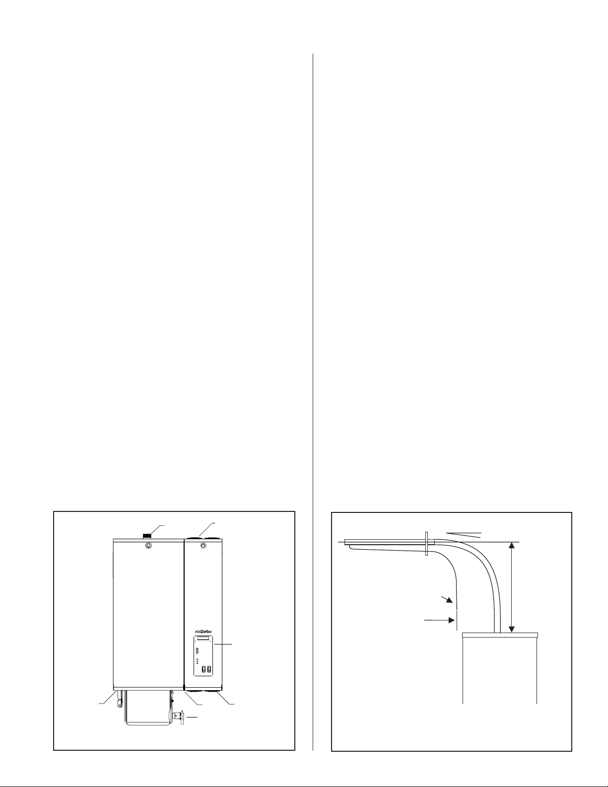
Figure #1
NHSC / NHDI Series Humidifier
SteamOutlet
1.75" O.D.
Water
Supply
NOTE: NHDI does not have the scale collector tank.
Scale
Collector
Tank
Spec
Label
Drain
Valve
Optional SSR
Cooling Fans
Keypad
Display
Power and
Control
Wiring
Figure #2
Minimum Steam Line Clearance
Min. 10 Degree Slope
Min. 12"
Trap
* See Section On
Condensate
Return Line
NOTE: Trap must be 3' minimum down from steam distributor
If not, condensate must be routed to drain.
-1-
Page 5
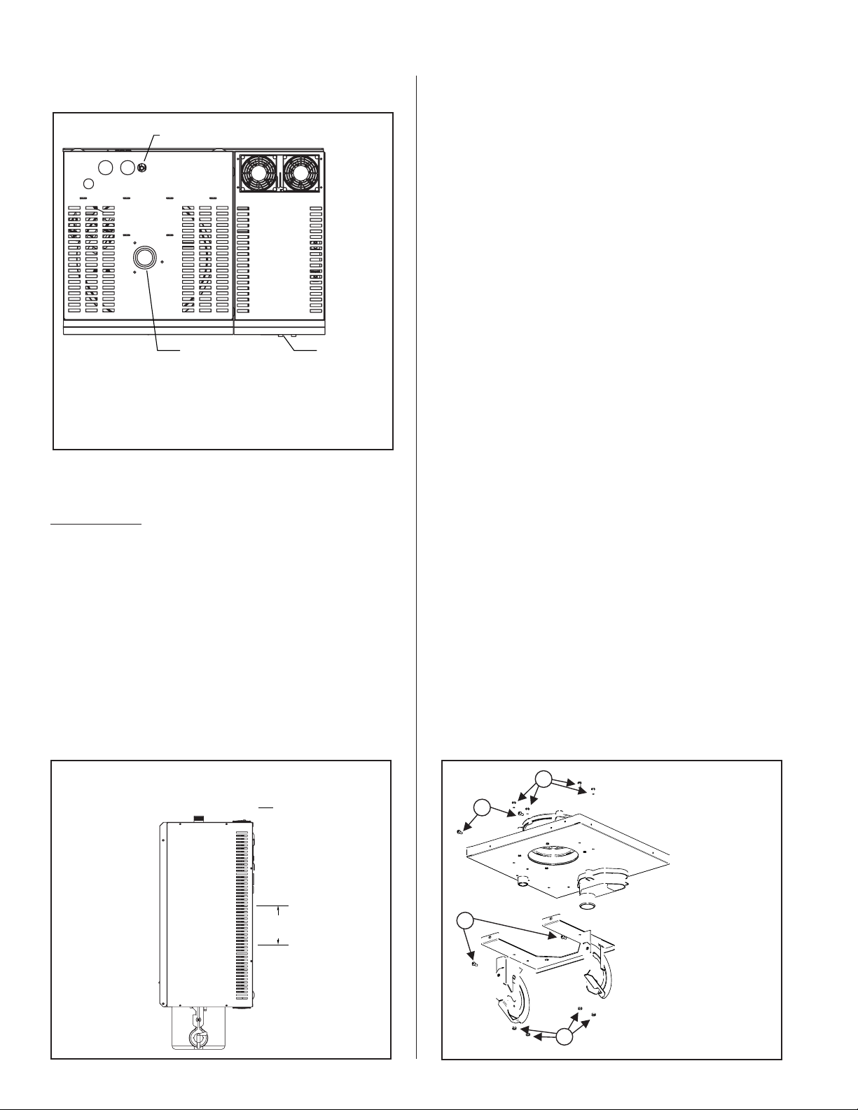
Figure #3
Clearance Required (Top View)
Condensate Return
Steam Outlet
NOTE: Local and national codes may deviate, please
consult applicable codes for clearance requirements.
Right side min. 36" side clearance. Min. 36" frontal
clearance recommended see note.
Top 12” Min, Bottom 12” Min, and Left Side 2” Min.
LOCATION & MOUNTING
HUMIDIFIERS
Right Side
Front
1. Location of the humidifier should be below and
as close as possible to the steam distributor
location. If possible, DO NOT locate humidifier
any further than absolutely necessary from
steam distributor location, as controllability
and net output will be reduced as a result of
heat loss through the steam hose (see Steam
Distribution Engineering Manual).
2. Where possible, mount humidifier at a height
convenient for servicing.
3. Wall mounting bracket provided should be
securely attached horizontally and open edge
facing upwards, using field-supplied fasteners.
For a single unit, use a minimum of 4 - #12 x
3” long wood screws. For a double unit, use a
minimum of 6 - #12 x 3” long wood screws.
These screws must be fastened securely on a
2 x 4 wood stud or equivalent support. If any
spacer material is used between the bracket
and the structural material such as drywall,
increase fastener length accordingly. In
addition, install a minimum of 2 field supplied
fasteners in the holes provided in the back of
the unit to prevent the unit from being bumped
off the wall bracket. See Figure #4.
NHSC / NHDI Series humidifiers are designed to
mount on a suitable wall or vertical surface. Do not sit
the unit on floor due to clearances required for
plumbing, electrical, and control entrances. The
clearance dimensions shown in this manual are for
reference only and are the minimum required for
maintenance of the humidifier. Local and National
Codes should be consulted prior to final location and
installation of the humidifier. NORTEC will not accept
responsibility for installation code violations.
Figure #4
Wall Bracket Mounting
Frontal clearance min. 36" (91 cm)
Right side clearance min. 36" (91 cm)
Left side clearance min. 2" (5 cm)
Wall
7.7"
(19.6 cm)
4. Mount unit on hanging bracket after ensuring
the bracket is properly anchored to the wall.
Raise the unit and place it on the hanging
bracket ensuring that the flanges in the
mounting bracket are properly aligned and
centered with the flanges of the unit. Push the
unit in towards the wall to properly interlock
the two flanges. Note: This will result in the
unit shifting slightly down. Ensure that the
hanging bracket’s flanges are fully engaged
Figure #5
Installation of the Scale Tank Bracket (NHSC only)
1.
2.
1) Line up holes in bracket with
3.
1.
holes in drain pan. Fasten the
bracket to the drain pan using
the four Nylon lock nuts
provided.
2) Fasten the front of bracket
with the two #10-24 self tapping
screws provided.
3) The two locking screws for the
bracket should already be
installed.
-2-
Page 6
and visible from within the plumbing section of
the unit, and that the unit’s flanges are
properly contained within the wall bracket.
5. Install tank bracket. See Figure #5. (NHSC
Version only). Mounting the scale tank. (NHSC
Version only).
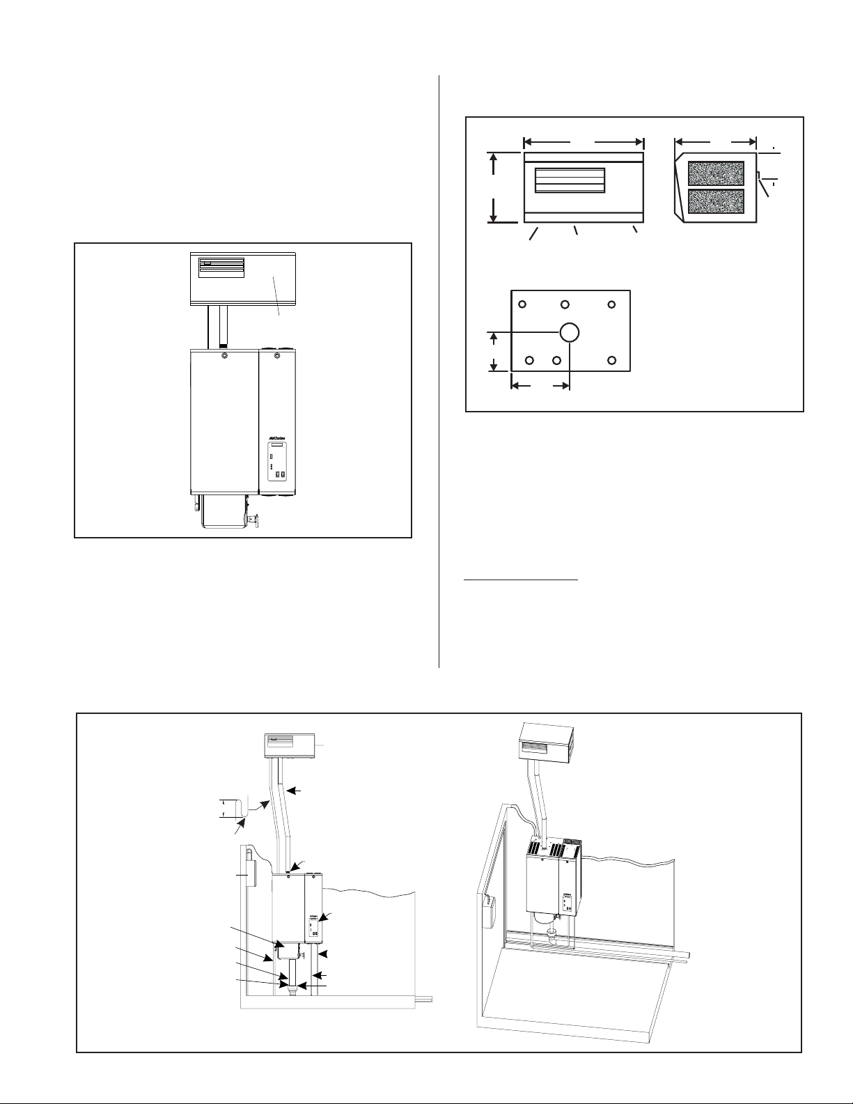
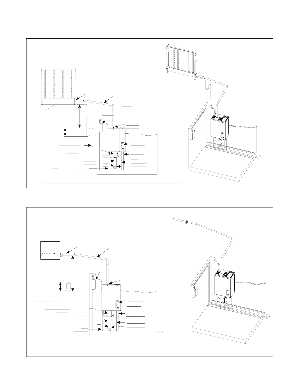
Figure #6
Remote Mounted Blower Pack
Figure #7
Remote Mounted Blower Packs (RMBP)
23.0"
(58.4 cm)
11.0"
(28.0 cm)
Condensate
Steam
Power
14.2"
(36.2 cm)
2.9"
(7.3 cm)
Wall
Mounting
Bracket
Remote
Mounted
Blower Pack
Scale
Collector
Tank
6. Make sure humidifier is level.
7. DO NOT mount humidifier on hot surfaces.
8. If humidifiers are mounted on roof, a
thermostatically ventilated weatherproof
Typical Remote Mounted Blower Pack Installation
Figure #8
Dimensions Shown
Are Steam Line Connections
Allow Minimum 12" (31 cm)
7.7"
(19.5 cm)
7.2"
(18.2 cm)
Clearance On Each Side
cabinet provided by others should be used.
Consult factory.
9. DO NOT mount humidifiers on vibrating
surfaces or duct work.
BLOWER PACKS
1. Blower packs are an optional accessory used
to directly distribute steam to localized areas
(such as computer rooms) or in structures that
do not have a built-in air distribution system.
Remote Mounted Blower
Packs (RMBP) Only
NHSC
uses Nortec steam
hose 1.75" O.D.or
stainless steel pipe.
uses Nortec steam
3"
Min. Trap
Height 3"
Required
Humidistat
Scale
Collector
Tank - NHSC
Water
Supply 3/8”
Drain Line
1.75” O.D.
Air
Gap
NHSC / NHDI using a Remote Mounted Blower Pack (RMBP)
NHDI
hose 1.75” O.D. or
stainless steel pipe.
Do not exceed 10 ft
when using steam hose.
Steam Line
Connection
LCD Keypad
Display with
LED Status
Low Voltage
Controls Wiring
24 Vac
Primary Wiring
Copper Funnel
Drain (by others)
-3-
Page 7

2. All NHSC / NHDI Series blower packs consist
of a steel cabinet containing: blower/motor
powered by voltage directly from the
humidifier, fuse, relay, speed select switch,
stainless steel steam distributor, supply air
grille with adjustable louvers, and a built-in
manual reset safety thermostat to turn off the
humidifier if the blower pack gets overheated.
Control thermostat, mounted on the steam
distributor, starts the fan when steam is
generated. When supply voltage differs from
voltage required to run blower motor, the
blower pack will contain the proper
transformer. All blower packs provide intake
air filters, if required.
3. For installation details about the blower pack,
please refer to the blower pack installation
manual located in the blower pack box, Form
#XX-277.
STEAM DISTRIBUTORS AND SHORT
ABSORPTION MANIFOLD
1.1. Steam distributors are an optional accessory
used to directly distribute steam to localized
areas (such as computer rooms) which are
served by ducted air. These distributors are
made of stainless steel and are mounted level
to the duct.
6. For installation details, please refer to the
installation manual located in the Steam
Distributor box, Form #XX-231.
7. For calculating absorption distances, refer to
H.E.L.P. Software or the Steam Distribution
Engineering Manual, Form #XX-232.
2. The SAM-e optional accessory has the same
function, to distribute steam inside a duct. The
only difference is that this system is designed
to reduce the absorption distance of the steam
in the duct by optimizing the steam
distributors.
3. Each cylinder requires its own steam line
and at least one distributor (do not join two
or more cylinders to one larger steam line).
Any cylinder’s steam line may be divided into
multiple branches to feed more than one
distributor. Steam supply line “tees” are
common stainless fittings that are available for
this purpose.
4. Steam distributor locations are typically as
follows: supply air duct, return air duct, air
handling unit. Proper location should
consider: air temperature, relative humidity
before the distributor, air velocity, dimensions
of the location, amount of steam being
introduced into the duct, downstream
obstructions, and surfaces vulnerable to
wetting.
5. The NHSC / NHDI can overcome 6” of W.C.
duct static pressure max. Consult the factory
if you exceed 6” of W.C.
-4-
Page 8
SAM-e
static pressure
Trap depth
2” greater
than duct
Min
24”
Condensate return
to floor drain, sump
pump or back to the
humidifier
Supply 3/8”
Steam
Inlet
Collector
Drain Line
1.75" O.D.
Water
Figure #9
Typical AHU / Duct Application using a SAM-e
NHSC
uses Nortec steam
hose 1.75” O.D. Or Med.
L Copper Insulated
NHDI
uses Nortec steam
hose 1.75” O.D. or
stainles steel pipe.
Do not exceed 10 ft
Gap
Air
when using steam hose.
Steam Line
Connection
LCD Keypad
Display with
LED Status
Low Voltage
Controls Wiring
24 Vac
Primary Wiring
Copper Funnel
Drain (by others)
Scale
Tank
NHSC
Humidistat
NHSC using a Short Absorption Manifold(SAM-e)in Duct/AHU
Figure #10
Typical Duct Application using Standard Distributor
NHSC
uses Nortec steam
hose 1.75” O.D. Or Med.
L Copper Insulated
NHDI
uses Nortec steam
hose 1.75” O.D. or
stainles steel pipe.
Do not exceed 10 ft
when using steam hose.
Steam Line
Connection
LCD Keypad
Display with
LED Status
Low Voltage
Controls Wiring
24 Vac
Primary Wiring
Copper Funnel
Drain (by others)
Condensate trap
must be 2” greater
than duct static
pressure.
Steam
Inlet
Min
24”
Scale
Collector
Tank
NHSC
Drain Line
1.75" O.D.
Water
Supply 3/8”
Humidistat
Air
Gap
NOTE: NHDI does not have the scale management system.
-5-
Page 9

PLUMBING
All water supply and drain line connections
should be installed in accordance with local
plumbing codes and should be copper or other
material suitable for potable water at 140ºF (60ºC).
WATER SUPPLY LINE - NHSC
1. The humidifier is intended to operate on
potable water.
2. Standard fill valves are sized for water
pressure ranging from 30 to 80 psig. For other
pressures, consult factory. This pressure
should be measured at the humidifier if the
water pressure is suspect.
3. ALWAYS supply and install a shut off valve in
the fill water supply line dedicated to the
humidifier to facilitate servicing. Use ½" OD
copper to within 4 feet of the humidifier.
Reduce to 3/8" OD and connect to the
factory-supplied 3/8" olive compression fitting
under the humidifier.
4. Same installation as #3, but add Drain Water
Cooler instead of fill.
#11). A field-supplied funnel (see Figure #12)
is recommended. It will prevent backup in the
drain pan and in the cylinder due to partially
blocked or badly installed drain lines. This
prevents rusting of the drain pan.
2. The NHSC scale collector tank is also
equipped with its own drain. It is
recommended to pipe, with a flex hose, the
scale collector tank to allow drainage, if
required while maintaining ease of servicing
(DO NOT HARDPIPE).
3. The drain line should not end in a sink used
frequently by personnel, or where plumbing
codes prohibit it. Route to a floor drain or
equivalent for safety reasons, since drain
water from humidifier can be very hot.
4. Keep drain lines as short as possible. Keep
drain lines sloped down, not level and not
up since low spots in drain lines will
accumulate sediment and cause backup.
The drain line should be 2.0” O.D. copper pipe
or larger. Do not use plastic pipe for drain
lines. Consult factory.
DRAIN LINE - NHDI
WATER SUPPLY LINE - NHDI
1. Humidifier is intended to operate on Reverse
Osmosis (RO) water or De-ionized (DI) water
with a water conductivity of less than 20
Microsiemens.
2. Standard fill valves are sized for water
pressure ranging from 30 to 80 psig. For other
pressures, consult factory. This pressure
should be measured at the humidifier if the
water pressure is suspect.
3. ALWAYS supply and install a shut-off valve in
the fill water supply line dedicated to the
humidifier to facilitate servicing. Use ½" OD
plastic or stainless steel to within 4 feet of the
humidifier. Reduce plastic or stainless steel to
3/8" OD and connect to the factory-supplied
3/8" olive compression fitting under the
humidifier.
4. Same installation as #3, but add Drain Water
Cooler instead of fill.
DRAIN LINE - NHSC
1. Humidifier is equipped with a 1.5”" O.D.
unthreaded drain outlet on underside of drain
canal on bottom of the humidifier (see Figure
1. Humidifier is equipped with a 1.5” O.D.
un-threaded drain outlet on underside of drain
canal on bottom of the humidifier (see Figure
#6). A field-supplied funnel (see Figure #8) is
recommended. It will prevent backup in the
drain pan and in the cylinder due to partially
blocked or badly installed drain lines. This
prevents rusting of the drain pan.
2. The drain line should not end in a sink used
frequently by personnel, or where plumbing
codes prohibit it. If the Drain Water Cooler is
used with potable water then copper may be
used. Route to a floor drain or equivalent for
safety reasons, since drain water from
humidifier can be very hot. Verify with local
codes on DI and RO water. Drains should be
verified for their suitability for RO or DI water
and local codes should be checked.
3. Keep drain lines as short as possible. Keep
drain lines sloped down, not level and not
up since low spots in drain lines will
accumulate sediment and cause backup.
The drain line should be 2.0” O.D. S.S. pipe or
larger. Do not use plastic pipe for drain lines.
Consult factory.
-6-
Page 10
l
A
Supply Water
t
Connection
3/8“
Drain
Water Cooler
Connection 3/8”
Drain
Connection
1.5" O.D.
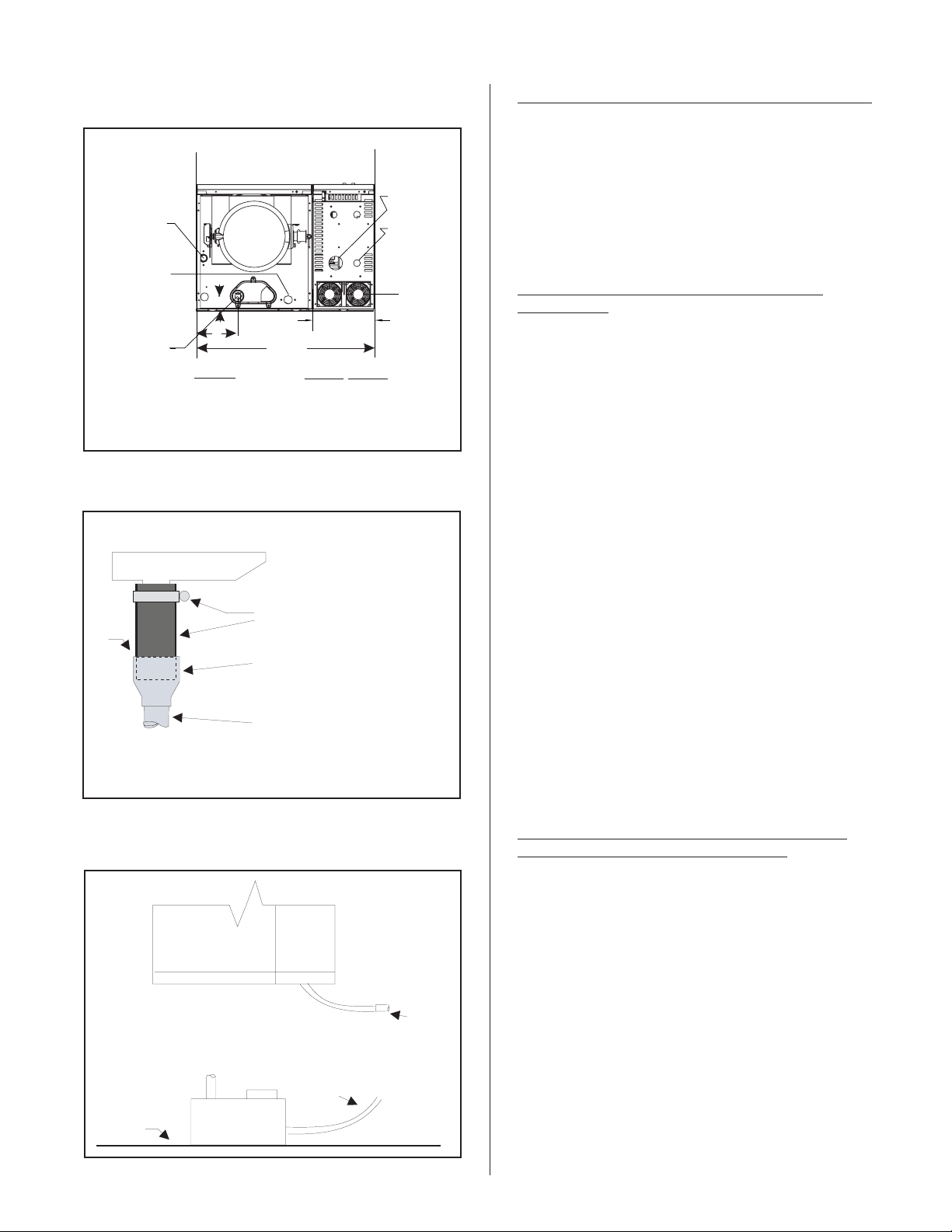
Figure #11
Drain Line Connection
NHSC
Scale
Collector
Tank
A
7.95
B
(58.4)
Model
010-090
135-180 Left
135-180 Right
23.0
(20.2)
A (in.)
1.7”
1.7”
1.7”
Figure #12
Drain Connection
B (in.)
5.4”
5.4”
20.3”
Power
Inlet
Controls
Inlet
Optional
Cooling Ki
for SSR
(consult
factory)
STEAM LINE AND CONDENSATE RETURN LINE
1. Refer to the installation manual of the steam
distribution system used in your application.
Steam Distributor Form #XX-231, SAM-e
Form #XX-249, and Blower Pack Form
#XX-277.
ELECTRICAL
PRIMARY VOLTAGE SUPPLY WIRING TO
HUMIDIFIER
1. Check and ensure that available voltage and
phase corresponds with operating voltage and
phase of humidifier as indicated on the
humidifier spec label, see Figure #1.
2. Ensure that an adequate power supply is
available to carry full humidifier amperage
drawn as specified by rated amps on the
humidifier spec label, reference to local codes.
3. A dedicated external disconnect must be
installed. Do not exceed the maximum circuit
protection amps as indicated on the
nameplate label.
ir
Gap
Clamp and1.5”ID Hose
Factory Supplied
Install aCopper Funnelfor theNHSC mode
and aStainless SteelFunnel forthe NHDI
model (byothers).
4. Connect ground wire to cabinet ground clamp.
Do not use neutral wire of four wire supply as
ground.
5. Single phase humidifiers may be run on three
phase power, but load may unbalance power
NOTE: Steam hose should not
reach bottom of the funnel.
Install a2” O.DCopper Pipefor theNHSC
model and2”O.D. Stainless SteelPipe for
the NHDImodel(by others).
grid.
6. External wiring sizes must be in accordance
with NEC and/or CEC and existing local
electrical codes and by-laws.
Figure #13
Drain Pump by others (if necessary)
PRIMARY VOLTAGE SUPPLY WIRING FROM
HUMIDIFIER(S) TO BLOWER PACKS
1. All blower packs are wired (by others) to be
powered from the humidifier.
Humidifier
2. As a safety feature, blower packs come
equipped with a manual reset safety
thermostat and relay built into the blower pack
cabinet. The manual reset thermostat turns
Recommended Model
Gould - Model SSH
Consult Factory
Floor
Surface
Line
Drain Line
off the humidifier if the blower pack gets
overheated. The control thermostat, mounted
on the steam distributor, starts the fan when
steam is generated.
3. All blower packs have high efficiency blowers
to minimize the frontal and overhead
clearance required to absorb the steam.
-7-
Page 11
(ACTUAL)
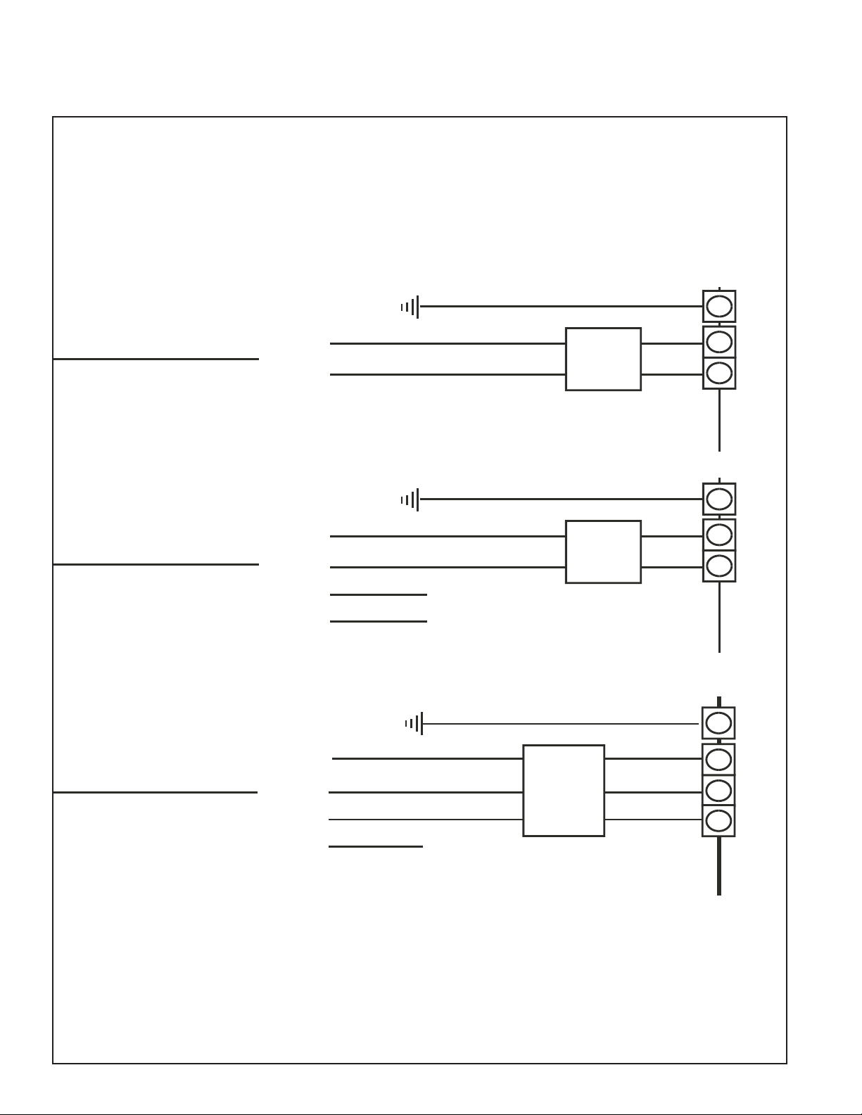
Figure #14
Primary Voltage Supply Wiring
PRIMARY (LINE) VOLTAGE WIRING TO UNITVOLTAGE
(BY OTHERS)
L1
L2
- Single Phase Unit.
- Single Phase Supply.
- Required Voltage Between L1 And L2.
- Load Balanced.
L1
L2
L3
Neutral
Ground
Ground
- Single Phase Unit.
- 3 Phase Supply.
- Required Voltage Between L1 And L2.
- Load Will Be Unbalanced.
Ground Wire
Dedicated
Disconnect
Ground Wire
Dedicated
Disconnect
Circuit
Breaker
Or
Circuit
Breaker
Or
Ground
Leg
2Pole
Te rm i na l
Block
E
I
X
N
T
T
Ground
Leg
2Pole
Te rm i na l
Block
E
I
X
N
T
T
Ground Wire
L1
L2
L3
Neutral
Ground
Dedicated
Circuit
Breaker
Or
Disconnect
- 3 Phase Unit.
- 3 Phase Supply.
- Required Voltage Between Any Two Legs.
- Load Will Be Balanced.
NOTE: VoltageAt TerminalBlock Must Be InAccordance With Spec. Label.
All Wiring ToBe InAccordance With Existing NationalAnd Local Electrical Codes.
-8-
Ground
Leg
3Pole
Te rm i na l
Block
E
I
X
N
T
T
Page 12
4, All blower packs require field wiring between
two pole primary voltage terminal blocks and
two low voltage control (class 1 circuit wiring
required) terminal strips; one of each located
in the humidifier and the remote blower pack
cabinet. To properly access the primary block
on the humidifier, it is necessary to open the
side pan. To connect the primary and control
(class 1 circuit wiring required) wiring, the
wiring is fed through the grommet provided in
the bottom of the blower pack. The terminal
block and strip are accessed by removing the
blower pack cover.
5. Field wiring of remote blower packs must
conform to national and local electrical codes.
Refer to wiring diagram supplied inside the
humidifier.
6. Use approved wire for power connection from
two pole terminal block of remote blower pack
to additional two pole terminal block inside
electrical section of humidifier.
7. Use approved wire to connect the ground
clamp of remote mounted blower pack to
ground clamp provided in the electrical section
of humidifier.
LOW VOLTAGE CONTROL WIRING
A - Wall or Duct Mounted Control On/Off
Humidistat: Wired to make on drop in humidity, break
on rise to set-point. Set to desired % RH. Can be a
make/break set of contacts from a Building Automation
System.
B - Duct Mounted Safety High Limit On/Off
Humidistat (if used): Wired to make on drop in
humidity, break on rise to safety set-point. Set to
approximately 85% RH as a safety to help prevent
saturation and wetting in the duct.
C - Duct Mounted Safety Air-Proving On/Off
Switch (if used): Wired to make with sensed air flow,
break when no air flow. Used as a safety to prevent
saturation when there is no airflow.
1. NORTEC offers various versions of A, B and
C to suit each application. In general, A is
essential, whereas B and C are highly
recommended in ducted applications.
2. Field wiring from humidistat to humidifier and
between devices should be 18 AWG or
heavier and kept as short as possible.
3. Low voltage control terminal strips are
provided in the electrical compartment.
Internal sides are factory wired. External
sides are to be field wired.
On-Off Controls
Figure #15
External Wiring of On/Off Controls
A
B
C
D
External
Internal
10
8
Controls are available from NORTEC as
accessories. If controls were not ordered with
humidifier, they must be supplied by others. The
following information is relevant to all controls, factory
supplied or otherwise.
A, B, C and D (described below) are to be wired in
series (only one path for current) across terminals 8
and 10 on the low voltage control terminal strip or
replaced with a jumper wire for constant operation.
Caution: this is the “hot” wire from the 24V control
transformer; it will blow the 3A fuse if any control field
wiring touches ground.
4. Each humidifier is supplied with a wiring
diagram inside.
D - Blower pack safeties
CONTROL INSTALLATION
1. Mount any wall humidistat (control or high
limit) over standard electrical box at height
similar to typical thermostat. Any wall
humidistat should be in location
representative of overall space being
humidified and not in path of blower pack or
air supply grille. Do not mount on a outside
wall where temperature fluctuation can affect
control response.
2. Mount duct humidistat in location
representative of overall air humidity, usually
in the return duct. Do not mount it directly in
front of steam distributor or in turbulent or
mixing zone. Mount it where humidity and
temperature are uniform and representative of
spaces being humidified.
3. Mount duct high limit humidistat
downstream of steam distributors far enough
that, under normal humidity and air flow
-9-
Page 13

temperature are uniform and representative of
s
spaces being humidified.
3. Mount duct high limit humidistat
downstream of steam distributors far enough
that, under normal humidity and air flow
conditions, steam will have been fully
absorbed (typically at least 10 feet). It must
be located to sense high humidity only when
uniform and representative air is
over-humidified or approaching saturation.
4. Mount duct air-proving switch so that it is
able to sense air flow or lack of it. Wire it to
make when air flow is sensed and break when
air flow fails.
5. Check operation of all on/off controls before
starting humidifier.
one of several control wiring diagrams. In all
cases, modulating signal interfaces through
control terminal strip to main pc board inside
humidifier.
4. For set-point control at the humidifier an
integrated controller can accept a direct
transducer signal. The accuracy of the
humidifier to changing conditions will be
dependant on the accuracy of the signal.
5. The modulation signal must increase from
minimum toward maximum as sensed RH
(actual RH) drops below desired RH (%RH
set-point). In response, humidifier’s steam
output will increase from minimum toward
maximum. When humidifier’s steam output
(lbs/hr) matches humidification load (lbs/hr),
modulation signal will stabilize.
6. Calibration of controls (on/off or modulation) in
the field may be necessary due to shipping
and handling. Verify humidistat accuracy
before commissioning system.
OPTIONAL MODULATION (CONTINUOUS
CONTROLS)
1. Read on/off controls section first since it is
necessary to all control systems.
2. Virtually any modulation (continuous control)
external hardware by others (as long as it has
%RH set-point circuitry) may be interfaced
with pre-specified factory-configured pc board
via the control terminal strip.
3. Modulation (continuous control) by others for
use with NHSC / NHDI humidifiers involves
Figure #16
Generalized Modulation Wiring
NHSC / NHDI SERIES
CONTROL CIRCUI T T ERMINAL BLOCK
IMPORTANT: REA D THESE INSTRUCTI ONS CAREF ULLY BEFORE CONNECTING CONT ROL WIRI NG
Other On/Off
Devices
High Limit
Humidistat
Air Proving
Switch
Control
Humidistat
NOTE: If no On/Off
Control is used, then
A field jumper must
be connected across
8 and 10 in order for
humidifier to operate
NOTE: See Included Diagram(s) For Accessory Wiring Instructions
NHDI: Dry Points, rated 24 Vac/dc 1.0Amp
max. resistive load per Indicator
OPTIONAL REMOTE
STATUS PCB
K1 Steam
K2 Error
K3 Ser vice
K4 Unit ON
Optional external remote
indication. Any or all of these
remote indications can be
utilized. Refer to Trouble
Shooting Manual for system
status indication.
10
8
Optional
Modulation Control
See Diagram included
with unit for details
32 30 28
61
6. Field-wiring connections for modulation control
are to be made to external side of terminals
28, 30 and 32 on humidifier’s control terminal
strip. Always refer to the external control’s
wiring diagram factory supplied with each
NORTEC modulation control option.
7. Varying dc Voltage Modulation Signal
Powered by Others: NHSC / NHDI
humidifiers can be factory configured to accept
the following vdc signals: 0-10 vdc, 0-20 vdc,
1-5 vdc or 2-10 vdc. Wire according to
NORTEC supplied external wiring diagram
that comes with each modulation option. To
share the signal with more than one
humidifier, wire in parallel to each humidifier.
If a different signal is desired consult factory.
8. Varying dc milliAmp (mA) Modulation
Signal Powered by Others: NHSC / NHDI
humidifiers can be factory-configured to
accept a standard dc mA signal, if
pre-specified. Wire according to NORTEC
supplied external wiring diagram that comes
with each modulation option. Choose from
0-20 dc mA or 4-20 dc mA. To share the
signal with more than one humidifier consult
factory.
9.
Varying Resistance (W) Modulation by
Others: NHSC / NHDI humidifiers can be
factory configured to power a 3-wire varying
resistance modulation humidistat by others, if
pre-specified. Wire according to NORTEC
supplied external wiring diagram that comes
with each modulation option. Choose from
0-500W or up to 0-1000W. To share the signal
with more than one humidifier consult factory.
-10-
Page 14

OPTIONAL MODULATION (CONTINUOUS
CONTROL) PACKAGES BY NORTEC
1. Modulation (continuous control) “packages”
are offered as accessories by NORTEC.
Power supply comes from inside NHSC /
NHDI humidifiers.
2. NORTEC provides the humidity set point
circuitry and sensor(s) for wall or duct
mounting or both as pre-selected when
ordering the option. NORTEC offers several
packages for NHSC / NHDI Series humidifiers.
Wire according to NORTEC supplied external
wiring that comes with each optional
modulation package.
control board. The humidifier’s operating status is
reported to the user by the green, red and yellow
indicator lights on the front of the unit.
The prerequisites for getting power and water into
the steam cylinder are as follows:
On/off switch must be switched on.
-
control circuit 8-10 must be made.
-
door interlock switch must be made (interlock switch
-
can be pulled out to operate unit).
Modulating signal must be calling.
-
Internal safeties must be made over temperature
-
switch and ground fault.
3. Optional modulation packages without
modulating safety high limit can use on-off
safety high limit. Refer to on-off controls
section.
4. All versions can use on-off safety air proving
switch. Refer to on-off controls section.
OPERATION
INTRODUCTION
The NORTEC NHSC Series humidifier is a
completely new design based on up-to-date
technology. The NHSC is designed to provide clean
steam humidification at an economical price.
The NHSC uses a micro-computer control system
for greater flexibility. The NHSC has a liquid crystal
display (LCD) to indicate system messages and
display RH.
LAYOUT AND FUNCTION
LEVEL REGULATION
The water level in the steam tank is continuously
monitored with the level unit.
The unit pulse fills based on steam production.
The pulse filling in the unit varies depending on the
water level detected by the float chamber.
One magnetic float monitors five different water
levels in the float chamber. The second float ensures
the water level is always above the heating elements.
The pressure equalizing pipe between the steam
connection and the level unit ensures that the water
levels are the same in the steam tank.
The NHSC humidifiers consist of a plumbing and
an electric compartment. In every case there is at
least one steam distributor (SD) for installation in air
ducts or blower packs (remote mounted: RMBP) for
direct space humidification.
Water enters the steam cylinder through the
bottom via the fill cup assembly when the 24 volt fill
valve solenoid is energized. The water is heated via
electric element and produces sterile steam for
distribution into the air.
Primary electric power is applied to the heating
elements in the steam cylinder when the on/off switch
is pushed on and all control options are calling. A
primary to 24 volt step-down transformer provides
power to the contactor holding coil(s) via the main
-11-
Page 15

STEAM GENERATION REGULATION
The steam is produced in the steam tank by
resistive heating element technology. An external or
the internal regulator for connection as required control
the steam production fully variably from 3 to 100%.
FLUSHING - NHSC ONLY
The evaporation process increases the
concentration of minerals in the water of the steam
cylinder. A suitable volume of water must be flushed
through the steam cylinder from time to time and
replaced by fresh water to ensure that this
concentration does not exceed a specific value
unsuitable for operation. The NHSC / NHDI steam
humidifier performs a flush cycle. This consists of the
following two forms of flushing.
Automatic flushing takes place as soon as the
•
water in the steam cylinder exceeds the upper
operating level (e.g. By foaming of the water).
Flushing is a time dependent process at
•
preselected time intervals.
Automatic or time-dependent flushing takes place
based on the water quality and the operating data.
SCALE COLLECTOR TANK - NHSC ONLY
The minerals precipitated by the evaporation
process accumulate at the bottom of the steam
cylinder. Units designed for operation with untreated
water are equipped with a scale collector tank located
directly underneath the steam cylinder. This way the
minerals do not accumulate in the steam cylinder but
mainly in the collector tank thus extending the service
intervals and reducing the maintenance costs.
NHSC / NHDI OPERATION
Ensure the valve on the NHSC mineral tank is
•
closed.
Switch on the steam humidifier main switch.
•
The steam humidifier carries out a system test.
The display below appears and the three LEDs light
for approx. 3 seconds.
test
If a fault is detected during the system test, a
corresponding fault message is triggered.
If the system test is successful, the steam cylinder
fills up and a float test is carried out (function check on
the level unit). The display below appears.
filling
Note: If a fault is detected during the float test, an
appropriate fault message is triggered
If the float test is successful, the NHSC / NHDI will
be in normal operating mode. The display below
appears and the green LED lights.
The following procedure should be carried out only
on the first occasion that the unit is operated:
NHSC/DI
ready
• Check the function of the steam humidifier:
•
Switch on the humidification by raising the set
humidity value on the humidity controller /
humidistat / NHSC / NHDI Display.
•
Switch off the humidification by lowering the set
humidity value on the humidity controller /
humidistat / NHSC / NHDI Display.
STARTING OPERATION
The following procedure should be carried out in order
to operate the steam humidifier:
•
Examine the steam humidifier and installation to
ensure it has been installed properly or for
possible damage.
Caution! Damaged units and units with
improper installation must not be operated.
•
Open the filter valve / shut-off valve in the water
feed line.
•
Switch on the external disconnect for the main
supply (Heating and control voltage).
•
Check for correct functioning of the monitoring
equipment (external safety network).
•
Set the desired humidity value on the humidity
controller/humidistat.
•
Make sure no leaks are present.
The heating current switches on as soon as the
humidity controller/humidistat demands humidity. The
yellow LED lights and steam is produced after a short
delay (approx. 5 minutes).
Operating status display on the unit
The operating status is displayed in the LED on
the unit as follows:
-12-
Page 16

Green LED lit: Unit producing steam
•
Yellow LED flashing: Major or minor servicing
•
due. The relevant notice is shown in the display.
Red LED flashing: There is a problem. The unit
•
is trying to solve the problem. The relevant
warning message appears in the display.
Red LED lit: Insoluble problem. The relevant
•
error message appears in the display.
Optional Remote operating and fault indication
If the steam humidifier is equipped with the
optional remote operating and fault indication
(option ”RFS”), the operating status will be shown as
follows:
K1 Steam (N/O) Normally open
K2 Error (N/O) Normally open
Or
(N/C) Normally closed
K3 Service (N/O) Normally open
Or
(N/C) Normally closed
K4 Unit On (N/O) Normally open
-13-
Page 17

INTERROGATION OF THE OPERATING
STATUS
The NHSC / NHDI operating and display unit has
a “display menu” from which various operating
parameters can be viewed.
Note: It is not possible to change the values on the
display level.
Operation
Call up the display level with <ê>or<é>.
<ê> next operating parameter.
<é> previous operating parameter.
Exit the display level with <Menu>
Internal Controller
Controller funct
off
Internal controller activated (”on”)/deactivated
(”off”)
Working Hours
elapsed time
623
Total of working hours elapsed since initial
commissioning of the steam humidifier.
Time Remaining to minor/major service
time to mainten.
600/1200
The time remaining (in hours) before the next
minor/major service.
Description of the operating parameters on the
display level
The following describes the individual operating
parameters that can be selected using the keys <ê>
and <é>, after the display level has been called up.
Steam Productions
steam-prod[%]
ref.=50/act=25
Current actual and nominal value of steam
production in percentage of total output.
Nominal value: Unit capacity x input signal value.
Actual value: max. Unit capacity x input signal
value x capacity limitation.
Note: If the internal controller is activated only the
actual value is shown.
Under the following conditions the actual value
may differ from the nominal value: upon activation of
the heating power, if capacity limitation is active during
the filling cycle of the steam cylinder.
Can be increased for poor water conditions or
decreased for good water conditions.
Figure #17
NHSC / NHDI Maintenance Intervals
Analog Input (humidity demand)
Analog input [%]
25
Current value of the signal applied to the analog
input in % of its max. value.
Note: If the internal controller is active the
displayed value corresponds to the current air humidity
(%rh).
-14-
Page 18

Note: The stated times are based on 100% steam
capacity. If the operation is at a lesser capacity, the
time should be extended accordingly. The servicing
intervals are set using the rotary switch “S2” on the
control board.
Drain Cycle
drain cycle
4: 120
The following indications are provided for the set
flushing interval:
Left: Switch setting on rotary switch “S1”
Right: Set flushing interval
Note: Water quality conditions resulting in
component failures are not covered under Nortec’s
standard warranty.
The factory settings are based on the following
water conditions when the unit leaves the factory.
Water
NHSC NHDI
Parameters
Conductivity 0-1500 MicroMhos 0-50 MicroMhos
Hardness 12 grains per gallon
(gpg)
0 grains per gallon
(gpg)
Note: The flushing interval is set on switch “S1” on
the control board.
Figure #18
NHSC / NHDI Drain Cycle Parameters
ValueSettings
Position Drai n Inte rval At 100%
S1 Steam Capacity
00Min.
1 720 Min.
2 360 Min.
3 180 Min.
4 120 Min.
560Min.
630Min.
720Min.
810Min.
95Min.
Factory Settings
NHSC - DI NHSC(S1) NHDI (S1)
Model Setting Setting
010 4 1
015 4 1
020 5 1
030 6 1
045 7 1
065 8 1
090 8 1
135 8 1
180 8 1
NHSC/NHDI
Main Board
Silica 12 parts per million
(ppm)
0 parts per million
(ppm)
PH 6.5-7.5 7
Chlorides > 50 parts per mil
lion (ppm)
> 25 parts per mil
lion (ppm)
Note: Should you have water conditions above the
stated parameters consult the factory for a new
blowdown setting to help improve your scale
management.
Chlorides
– High levels of chlorides will attack
stainless steel. The solution would be to add an in-line
carbon filter that will remove up to 99% of the
chlorides. Consult the factory for additional information
if your water contains high levels of chlorides.
Nortec recommends performing a semi-annual
water analysis to ensure optimal performance.
Stand-by Heating
stand-by heating
off
-
Drain
Interval (S1)
Example:
Position
4:120
NOTE: Approximately 1 liter or
0.26 gallons will drain during
these intervals. Drain Water
Cooling will be active during
these intervals to temper the
drain water to 140 degrees F (60
degrees C) or less.
LCD
Display
Duration between
drain cycles
Stand-by heating activated (”on”) deactivated
(”off”).
Note: If stand-by heating is active the water
temperature in the steam cylinder is constantly kept at
approximately 70ºC (158ºF) by the control board.
Capacity Limitation
power limit [%]
100
The set capacity limitation as a percentage of the
maximum capacity. Press both arrow keys at the
same time and a code will appear. Enter 8808 using
the arrow keys on the keypad and scroll down to the
-15-
Page 19

power limit screen. To change the power limit, simply
press the down aroow key to desired capacity and
press enter to save that new value. Press menu key
to exit parameter screen.
Inlet Valve Correction
inlet valve cor.
130
Set inlet valve correction (cycle ratio) in % of
standard setting value to balance out water pressure
variations.
Figure #19
NHSC / NHDI Control Interval
Soft Start
Soft Start
Off
Soft Start activated (on), consult factory.
Deactivated (off) factory set.
Demineral Mode
Demineral Mode
Off
Demineral mode activated (on), consult factory.
Deactivated (off) factory set.
Serial Interface
Serial Interface
Off
Serial Interface activated (on), consult factory.
Deactivated (off) factory set.
Full Drain Cycle
Full Drain Cycle activated (on), consult factory.
Deactivated (off) factory set.
Flush Cycle
Flush Cycle
Off
Flush Cycle activated (on), consult factory.
Deactivated (off) factory set.
Control Signal
analog signal
0 - 5v (poti)
Range of the active analog signal in V or mA,
respectively.
Note: The range of the analog signal may be
adjusted using the rotary switch “S3” on the control
board.
Software Version
software version
VX.XX
Current software version for the steam humidifier.
-16-
Page 20

Unit Type
machine type
xxlb/xxxV
Warning:
In order to eliminate faults, the steam
humidifier must be switched off and secured against
unintentional re-connection. Take care that the
electricity supply to the main contactor is disconnected
(check with voltage meter).
Only allow trained and qualified personnel to
repair faults. Faults relating to electrical installation
(e.g. change of unit fuse) must only be carried out by
authorized personnel.
Repair work and replacement of faulty
components must only be carried out by your service
technician!
NOTES ON MAINTENANCE
Figure #21
Major Maintenance - NHSC / NHDI
NHSC Maintenance
Complete cleaning
(between 600 - 6000
hours of operation)
- Unit indicates cleaning is
required.
- This cleaning normally occurs
once a year(depends on water
quality).
- The scale collector tank and the
stainless steel tank are removed
and cleaned.
- Check all plumbing and
electrical components for any
issues.
MAINTENANCE
All maintenance work must be performed by
adequately qualified and trained personnel familiar
with the dangers involved. Ascertaining the
qualifications is the customer’s responsibility.
Instructions and details concerning the
maintenance work must be observed and adhered to
without fail.
Only the type of maintenance work outlined in this
documentation must be carried out.
Figure #20
Minor Servicing - NHSC ONLY
To safeguard reliable operation, the maintenance
of the NHSC should be devised in three stages. A
distinction is made here between periodic inspections,
minor servicing and major maintenance of the
steam-air humidifier.
The intervals required between minor servicing
and major maintenance depend on the water quality
and the quality of steam generated and can be
pre-selected on the rotary switch “S2” on the control
board. After expiry of the selected interval, the yellow
LED flashed and an appropriate message alternates
with the normal operation indication.
The following is an overview of the work that
should be undertaken for the three maintenance
stages.
Periodic Inspections
When Once per week
Work Inspect the water and steam
installations for correct sealing and any
possible damage.
Use original spare parts exclusively to replace
defective parts.
Before maintenance is initiated, the steam
humidifier must be taken out of operation in
accordance with instructions in the manual and
protected against unintentionally switching on the
humidifier.
Inspect the drain line for soiling.
Inspect the electrical installation for
loose cables and damaged
components.
Inspect the humidifier for irregularities
both external and internal.
-17-
Page 21

Minor Maintenance
Work Carry out the periodic inspection items.
When The yellow LED flashes and the
message “minor servicing due”
appears, alternating with the normal
operation indication.
Work Carry out the periodic inspection items.
Empty the steam cylinder and clean the
scale collector tank.
Figure #22Scale Tank Removal
1.
5.
3.
2.
4.
1.
Turn unit off.
2.
Drain unit and scale tank.
3.
Unlock support bracket by removing locking screws.
4.
Open both mechanisms by rotating counter clockwise until opening is visible.
5.
Place scale tank on support bracket.
6.
Rotate bracket to close mechanism and raise scale tank. Note ensure scale
tank lines up with opening at the bottom of the drain pan when raising.
7.
Lock mechanism by re-inserting the two locking screws.
Empty the steam tank.
Clean the scale collector tank (NHSC
Only).
Dismantle and clean the steam
cylinder.
Dismantle and clean the liner (NHSC
Only).
Clean the unit inner chamber.
Inspect the components inside the unit
for damage.
Resetting Minor and Major Maintenance
In order to return the steam humidifier to normal
operation after minor or major maintenance is
complete, you must press and hold down the drain
switch while turning the unit in the OFF position for
approxiamately 10 seconds. Then turn the unit switch
back onfor 10 seconds and release the drain switch
and the LCD message will return to normal.
DISMANTLING AND REASSEMBLY WORK
Major Maintenance
When The yellow LED flashed and the
message “major maintenance due”
appears, alternating with the normal
operation indication.
Removal of the scale collector tank - NHSC Only
Caution!
Before commencing any dismantling
work, the humidifier is to be taken out of operation as
previously described.
NOTES ON CLEANING - NHSC Only
Cleaning the steam cylinder, scale collector tank,
and steam cylinder liner.
Whenever possible, clean off any mineral coating
that has formed.
Wash parts with lukewarm soap suds and then
rinse off well. Note: if the components are heavily
scaled, place them in 8 percent formic acid until the
scale has dissolved. Then treat components as
previously described.
Cleaning the heating elements
Immerse cover with heating elements fitted to 1”
(2 cm) below the rim of the cover in a container with 8
percent formic acid. Ensure electrical wires do not
make contact (do not fully submerge). Allow the acid
to take effect until the scale coating has dissolved.
-18-
Page 22

Note: The heating elements do not have to be entirely
free from scale.
Then rinse heating elements thoroughly with fresh
water.
Warning! Ensure that the electrical connections
remain dry.
Turn on the humidifier with the unit switch.
Continue to depress the blow-off pushbutton until
the system test has finished (approx. 10 seconds).
FAULT ELIMINATION
Fault indication
Warning! Do not remove scale coating on the
heating elements with tools (screwdriver, scraper, etc.)
or by striking. This could damage the heating
elements.
Cleaning the interior of the unit
Wipe down components inside the unit with a
damp cloth (clean water). Severely scaled
components, e.g. the inlet funnel and the blow-off
pump, should be cleaned using commercially available
cleaning and descaling agents.
Warning! The electrical connections and
electronic components must remain dry.
Notes on Cleaning Agents
Warning! Formic acid is harmless to the skin but it
attacks the mucous membranes. Protect the eyes and
respiratory tracts from contact with the acid and its
vapor (wear goggles and work in a well ventilated
room or outside).
The use of disinfectants is only permitted if they
leave no toxic residues. The components must be
rinsed thoroughly with water after cleaning in all cases.
Caution! Do not use any solvents, aromatized
or halogenized hydrocarbons, or other aggressive
substances for cleaning purposes.
In case of malfunction during operation, the
humidifier control checks whether there is a temporary
problem (e.g. water supply interrupted for a short time)
or whether it can resolve the problem by taking
necessary measures. Such malfunctions set the unit
into the “Alarm” status (fault elimination). The red
LED flashes and an alarm message appears in the
display alternating with the notice “recovering -
please wait”.
Note: If the cause of the malfunction disappears of
its own accord or if the controls can repair the
malfunction, the alarm message will automatically
switch off.
Note: If the unit is in display or setting level the
alarm message in the display will be suppressed.
If the controller, after several attempts, fails to
solve the problem (number of attempts depends on the
type of malfunction) or if the problem obstructs further
operation, the heating voltage is interrupted via the
main contactor. The red LED stays lit and an error
message appears in the display alternating with the
notice “Please turn off unit”.
Note: If the unit is in the display or setting level the
error message in the display will be suppressed.
The information and instructions regarding
cleaning agents are to be strictly observed and
implemented. In particular: Information relating to the
protection of personnel, environmental conservation
and restrictions regarding usage should be adhered to.
In all cases, local regulations relating to
environmental protection must be implemented.
To reset the maintenance indication
When maintenance work has been completed, the
maintenance display can be reset as follows:
Turn on the service switches in the main supply
line.
With the unit switched off depress and hold the
drain switch.
-19-
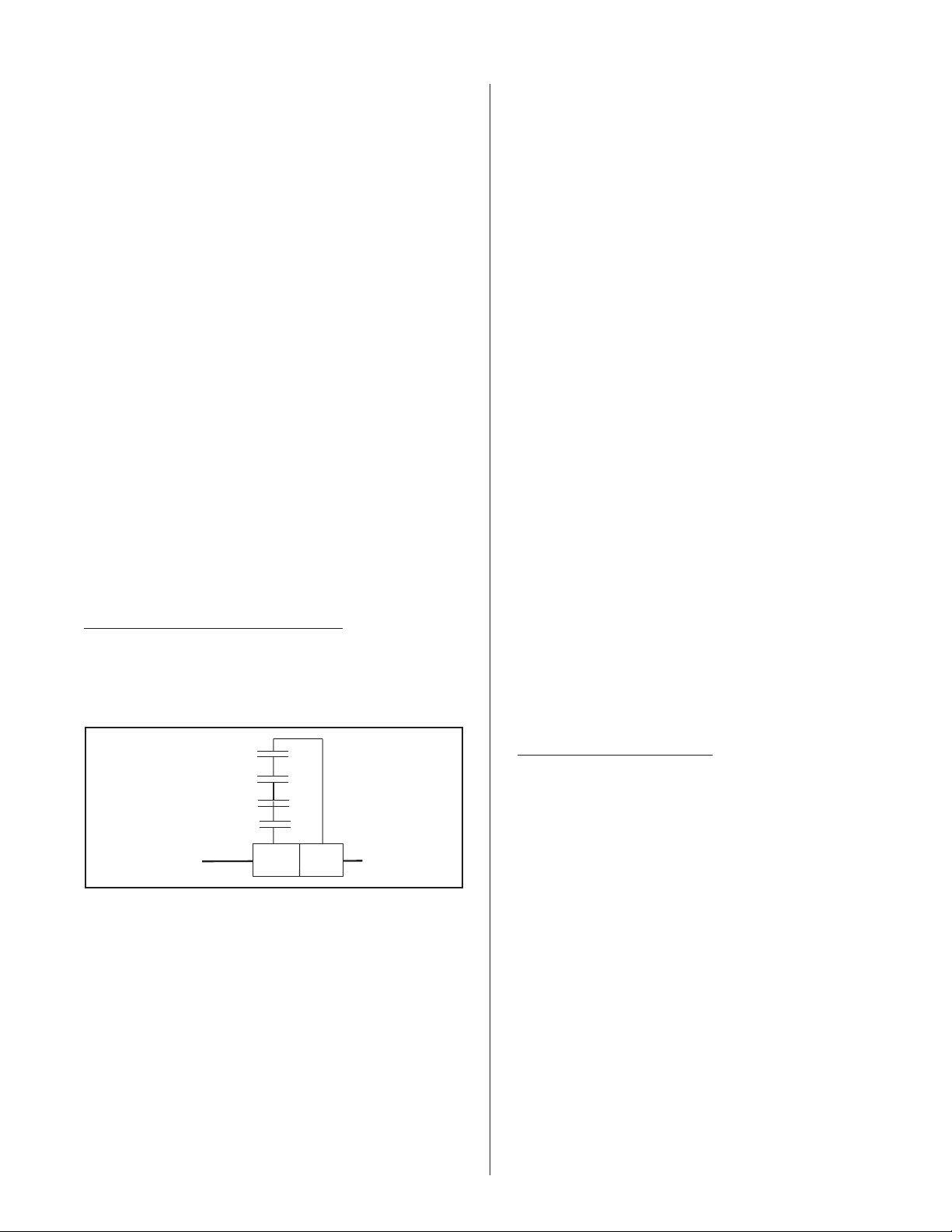
Page 23

2
ON
OFFDRAIN
1
Scale
Tank
Collector
T
ank support
6
PN: 150-5913 Rev. A
SCALE COLLECTOR TANK SERVICING
1. Drain Cylinder.
2. Turn off the unit.
water
3. Open manual drain valve on Scale Tank to drain remaining
4. Disconnect hose connection on scale tank.
mechanism.
5. Remove locking screws on the front of the Scale
-20-
6. Lower and remove Scale Tank.
7. Visually inspect cylinder, heating elements and o-ring. Clean or
replace if necessary.
Note: Scale collector tank has to be removed after 5000 hours
or 3 years, whichever comes first.
Scale tank last replaced on:
Page 24

REPLACING UNIT FUSES
Open the plumbing door.
3.
Warning! Before replacing the unit fuse the
steam humidifier must be switched off and
secured against unintentional re-connection. Take
care that the electricity supply to the main contactor is
disconnected (check with voltage tester).
Warning! Electronic components are very
sensitive to electrostatic discharge. To protect these
components, measures must be taken against
damage from electrostatic discharge when replacing
the unit fuse (ESD protection).
The unit fuses may only be replaced by trained
and qualified personnel.
Important! If the unit fuse blows this is generally
due to a faulty unit component. Therefore you should
check these components before replacing the fuse
(see table below).
Only use the correct type of fuse according to the
following table.
Warning! It is not permitted to use repaired fuses.
Let unit tank cool down if needed.
4.
Remove steam hose by loosening gear clamp.
5.
Disconnect temperature switch. Note there is
6.
no polarity with this cable.
Remove gear clamp and remove tank from the
7.
unit
8. Undo cylinder tank strap and remove tank
from unit.
9. Remove lid clamp, open lid and identify
heating elements to be replaced.
10. Remove the nut, washer, plug and gasket
from the top of heating element you are
replacing. Note: Save the hardware for
installing the new heating element.
11. Note the heating element orientations, and
remove heating element by pulling it down
through the lid.
Fuse Specification Before replacing,
F1 on supply
module
F2 on supply
module
F5 on control
board
RESETTING FAULT INDICATION “ERROR”
In order to return the steam humidifier to operation
after fault indication error, you must press and hold
down the drain switch while turning the unit in the off
position for approximately 10 seconds. Then turn the
unit switch back on and release the drain switch after a
10 second interval.
6.3 A,
slow-acting
1A,
quick-acting
50mA,
quick-acting
check
Drain pump (blocked
or coil faulty)
Inlet valve (blocked
or coil faulty)
Control signal
HEATING ELEMENT REPLACEMENT
INSTALLATION INSTRUCTIONS
12. Place gasket from step 15 on new heating
element and install new heating element by
inserting it into the lid from the bottom
ensuring orientation matches previous heating
element.
13. Re-install gasket, plug, washer, and nut.
Tighten assembly
14. Connect element pins into the male connector
by pushing in the pins and they should lock
into place, pull to ensure.
15. Ensure all heating element fastening nuts are
tight.
16. Re-install cylinder tank lid, clamp on cylinder
and re-install the tank in the unit. Take care to
ensure that the tank is level in the base and
that the connecting components are aligned.
17. Fasten the cylinder into position using the
cylinder strap.
18. Re-connect steam hose and clamp to steam
output coupling.
Drain unit.
1.
Turn off the unit, and disconnect primary
2.
power to the unit.
19. Connect female connector to the male
connector.
-21-
Page 25

Figure #23
Element Pins
Heating Element
20. Connect temperature switch cable. Note: This
cable is not polarity sensitive.
21. Double-check all the connections.
22. Turn the unit on.
23. Allow unit to fill.
24. Inspect unit operation and check for leaks.
25. Close and lock plumbing door.
-22-
Page 26

TROUBLE-SHOOTING
Most operational malfunctions are not caused by faulty equipment but rather by improper installation or disregard
for planning guidelines. Therefore, a complete fault diagnosis always involves a thorough examination of the entire
system. Often, the steam hose connection has not been properly executed or the fault lies with the humidity control
system. The following table gives a list of possible malfunctions, the appropriate alarm or error message, details of
their cause, and notes on how to deal with each problem.
Malfunction / Indication Cause Remedy
Min. Filling time too short
Error code: 1A/1B
Alarm 1A
filling time
Error 1B
filling time
Internal safety chain interrupted
Error code: 2A/2B
Alarm 2A
safety chain int
Error 2B
safety chain int
Max. Filling time exceeded (alarm
message only)
Error code: 3A/3B
Alarm 3A
water supply
Water feed to steam cylinder heavily
calcified.
Level in steam cylinder and level unit
do not match.
Connection to over-temperature
switch on steam cylinder broken or
over-temperature switch faulty.
Steam cylinder overheating,
over-temperature switch has
responded.
Flat-band cable between control and
power board interrupted or not
connected.
Water feed blocked (main water tap
closed, filter valve closed or blocked).
Water pressure too low.
Inlet valve does not open, filter sieve
in Inlet valve blocked or inlet valve
faulty.
Feed hoses into the steam humidifier
not connected or kinked.
Level unit not connected.
Float in the level unit sticking or level
unit faulty.
Carry out major servicing.
Check connections or replace
over-temperature switch.
Inspect steam cylinder, clean if
necessary. Replace over-temperature
switch.
Inspect connections, connect or
replace flatband cable.
Check water feed, open main water
tap, open or clean filter valve.
Raise water pressure (range 1-10
bar).
Inspect electrical connections and
fuse F2 on supply module. Clean filter
sieve or replace Inlet valve.
Inspect hoses into unit and connect if
necessary. Replace faulty hoses.
Connect level unit.
Clean or replace level unit.
Max. Boil down rate too long
Error code: 4A/4B
Alarm 4A
steam time
Error 4B
steam time
Max. Drain time exceeded
Error code: 5A/5B
Alarm 5A
drain
Error 5B
drain
Individual heating elements faulty.
Main voltage too low or failure of a
phase (L1, L2 or L3).
Steam line too long or not insulated.
Drain pump not connected or faulty.
Outlet line from unit kinked or
blocked.
Water outlet blocked (external outlet
line or siphon blocked.
Hose to level unit blocked.
-23-
Replace faulty heating elements.
Replace fuses on power board.
Check main voltage and
connections.
Maintain maximum line lengths
(max. 15’). Insulate steam lines.
Connect or replace drain pump.
Inspect outlet line from unit, replace if
necessary.
Clean water outlet line and siphon.
Clean or replace hose.
Page 27

Malfunction / Indication Cause Remedy
Invalid level
Error code: 6A/6B
Alarm 6A
level indicat
Error 6B
level indicat
Steam pressure (error only)
Error code: 7A/7B
Alarm 7A
communication
External safety chain interrupted
Error code: none
safety chain
external A
mains failure
B
Level unit faulty.
Magnetic field in vicinity of level unit.
Steam hose blocked or restricted
(water trap).
Pressure balance adapter into steam
connection fitting blocked.
Duct pressure too high (>1500 Pa).
Ventilator lock open.
Automatic flow control has
responded.
Safties are open.
Main failure on Unit B. Inspect voltage supply to Unit B.
Replace level unit.
Eliminate magnetic field.
Inspect steam hose, clean if
necessary and install correctly.
Remove adapter and clean opening
with a needle.
Inspect ventilation settings.
Switch on ventilator/ventilation
system.
Inspect ventilator/filter of ventilation
system.
Servicing, inspect system if
necessary.
LEGEND
A = Circuit 1
B= Circuit 2 (double unit 2nd
cylinder)
-24-
Page 28

NHDI: Dry Points, rated 24 Vac/dc 1.0 Amps
max. resistive load per Indicator
OPTIONAL REMOTE
ST AT US PC B
Optional
K1 St e a m
status indication.
indication. Any or all of these
remote indications can be
utilized. Refer to Trouble
Shooting Manual for system
INSTALLATION INSTRUCTIONS
ACCESSORY
DIAGRAM No. 1508104 Rev. A Nov. 21, 2003
K3 Se r v i c e
K2 E r r o r
K4 U n i t O N
Optional external remote
61
NHSC / NHDI SERIES
CONTROL CIRCUIT TERMINAL BLOCK
NOTE: See Included Diagram(s) ForAccessory Wiring Instructions
IMPORTANT: READ THESE INSTRUCTIONS CAREFULLY BEFORE CONNECTING CONTROL WIRING
with unit for details
Modulation Control
See Diagram included
32 30 28
10
8
Air Proving
Hig h Lim it
OtherOn/Off
Devic es
Hum idistat
Sw i tc h
Control
Hum idistat
ield jumper must
NOTE: If no On/Off
Control is used, then
be connected across
8 and 10 in order for
af
humidifier to operate
-25-
Page 29

NHSC / NHDI Electric Steam Humidifier
Humidifier Mandatory Pre-Start-up Checklist (p.1 of 2)
Unit Serial #: ________ # of humidifiers: _____ Tag:_____________
Unit type: NHSC / NHDI
Customer/Job:_______________ Address: __________________________________________________
Inspected by: _____________ Date of inspection: ___/___/___
______________________________________________________________________________________________
W
WATER QUALITY:
- Well water r -City water r -Softened water r
- Conductivity: _______mhmos - Hardness: _____gr. –Silica____ppm
Voltage: _____V/___ph Steam output: ____lbs./hr
HUMIDIFIER MOUNTING:
Clearances around the unit Acceptable Obstruction
- Front (door opens freely?) 3ft min
- Top (steam lines) 1ft min r ____________________
- Bottom (fill, drain, controls) 1ft min
- Right (main pwr) 3ft min
- Left (main pwr) 2” min
- Ensure the scale tank bracket is locked in place
r _______________
r ____________________
r ____________________
r ____________________
r
STEAM LINES: CONDENSATE LINES:
- Slope up 2” per 12” r - Slopped back to drain r
- Slope down ½” per 12” r - Trapped 2” more than static duct pressure r
- Traps r - Size _______
- Insulated
- Length/Size ____________
- 90 deg. elbows qty: ____ - 45 deg. Elbows qty: ____
- Can condensate be trapped anywhere in the steam line? Yes
r
r no r
WATER LINES:
-½” at max 4ft from the unit - 3/8” connection at fill
-water pressure: 30-80psig
DRAIN LINES:
-Air gap located within 3ft of the unit r - Slopped to drain r -Size:________
WIRING:
No loose wires around the unit or on the PC board? Yes r no r
CONTROLS:
Installed Location / Wiring /Setting
- High limit:
- Air proving:
- Mod controller:
- Other:
r _____________________
r _____________________
r _____________________
r _____________________
POWER
- Voltage, amperage rating and fuse corresponds to Spec Label r
- Disconnect switch located close to humidifier r
Field contact:___________________________ Signature:_______________________________
Page 30

NHSC / NHDI Electric Steam Humidifier
Humidifier Mandatory Start-up Checklist (p. 2 of 2)
Unit Serial #: ________ # of humidifiers: _____ Tag: _____________
Unit type: NHSC / NHDI
Customer/Job: _______________ Address: _________________________________________________
Start-up by: _____________ Date of start-up: ___/___/___
______________________________________________________________________________________
Voltage: _____V/___ph Steam output: ____lbs./hr
1. PRELIMINARY:
- Pre-start-up checklist completed? yes r no r
If no, return to Pre-Start-up Checklist before going on with start-up procedure.
2.START-UP PROCEDURE:
The prerequisites for getting power and water into the steam cylinder are as follows:
- check that main breaker is on and power is at the unit
- check that main water shut-off valve is open
- on/off/drain switch must be switched on
- control circuit 8-10 must be made
- modulation humidistat, if present, must be calling
- door interlock switch must be made (interlock switch can be pulled out to operate unit)
The unit will undergo a System Test
will fill and the float test will be carried out. If everything ok, the green light will come on and the display will
show NHDI or NHSC Ready
.
to ensure integrity of all the components. If the test is successful, the unit
3. OPERATIONAL CHECK:
-Switch on the humidification by raising the humidity set point on the humidistat/controller.
-Switch off the humidification by lowering the humidity set point on the humidistat/controller.
-Check for correct functioning of the external monitoring safeties such as air proving and high limit.
-When check complete: Set the desired humidity level.
Remarks:__________________________________________________________________________________
__________________________________________________________________________________________
__________________________________________________________________________________________
__________________________________________________________________________________________
__________________________________________________________________________________________
__________________________________________________________________________________________.
-27-
Page 31

NHSC / NHDI Electric Steam Humidifier
Maintenance Checklist (p.1 of 2)
Unit Serial #: ________ # of humidifiers: _____ Tag: _____________
Unit type: NHSC / NHDI
Customer/Job: _______________ Address: _________________________________________________
Maintenance by: _____________ Date of maintenance:___/___/___
______________________________________________________________________________________
Type of maintenance:
Voltage: _____V/___ph Steam output: ____lbs./hr
Periodic maintenance, once per week:
- Inspect water and steam installation lines for leaks
- Inspect drain lines for clogging
- Inspect electrical installation for loose cables and damaged components.
- Inspect the humidifier for damage.
Minor servicing, when the yellow LED flashes and display indicates minor maintenance due:
- Carry out periodic inspection items
- Empty the steam cylinder and clean the mineral collector.
Major servicing, when the yellow LED flashes and display indicates major maintenance due:
- Carry out periodic inspection items
- Empty the steam cylinder and clean the mineral collector.
- Dismantle and clean the steam cylinder
- Clean the unit inner chamber
- Inspect the inside components for damage.
Note: Time interval between minor and major are set through rotary switch #2 on the control board.
Cleaning recommendations for the Steam cylinder, mineral collector tank (NHSC Only) and
steam cylinder (NHSC Only) insert:
- Drain unit completely including mineral collector tank drain
- Remove lime collector tank, remove steam cylinder
- Whenever possible, chip off or scrape off any scale coating
- Wash and rinse parts with lukewarm soap water (If components are heavily scaled, place them
in 8% formic acid until the scale has dissolved. Then treat components as previously described.)
Cleaning recommendations for heating elements:
- Wash and rinse heating with lukewarm soap water (If components are heavily scaled, place
them in 8% formic acid until the scale has dissolved. Then treat components as previously described.)
Warning: On no account remove scale coating on the heating element with tools or by striking. This
could damage the heating element.
Cleaning recommendations for internal plumbing components:
- Wipe down components inside the unit with a damp cloth (clean water).
- Severely scaled components should be cleaned using commercially available cleaning and
de-scaling agents.
Warning: Ensure electrical connections remain dry!!!
For more information on cleaning agents and formic acid, review notes in the installation manual.
-28-
Page 32

NHSC / NHDI Electric Steam Humidifier
Maintenance Checklist (p.2 of 2)
Note: In all cases, local regulations relating to environmental protection must be implemented.
How to reset the maintenance indication:
- Switch on the services in the main supply lines.
- With the unit switch off, depress and hold the drain switch.
- Switch on the steam humidifier with the unit switch
- Continue to depress the drain button until the system test has finished (approx 10 sec.)
Comments:
________________________________________________________________________________________
________________________________________________________________________________________
________________________________________________________________________________________
________________________________________________________________________________________
________________________________________________________________________________________
________________________________________________________________________________________
-29-
Page 33

-30-
Page 34

Electrical Exploded View
-31-
Page 35

28
30
31
32
33
34
35
36
39
40
22
27
26
25
24
23
29
37
38
1
2
2
16
12
3
4
5
9
8
6
7
21
20
19
18
1517
11
10
13
14
-32-
Page 36

Plumbing Exploded View
Capacity 180/3
Voltage
Nortec PN Description
1 1502644Pump,Drain24V60Hz 11111111111111111111111111112222
2 1506286FillValveDWCAssembly 11111111111111111111111111112222
3 1455000GasketforFillThruCabinet 22222222222222222222222222224444
4 1505905DrainCanalGasket 11111111111111111111111111112222
5 1502638DrainCanal 11111111111111111111111111112222
6 1505914ScaleTankBracketNHSCOnly 11111111111111111111111111112222
7 1505915ScaleTankAssemblyNHSCOnly 11111111111111111111111111112222
8 1508023GroundWireDoortoCabinet 11111111111111111111111111112222
9 1502588Bracket-CabinetLargeCylinder 11111111111111111111111111112222
10 1328860 Hose Fill Cup ORDER BY THE INCH
11 1325035SpringClamp-Hose 22222222222222222222222222224444
12 1502944O-ring-NHDITankBase 11111111111111111111111111112222
13 1505906 O-ring - NHSC Only
14 1507780
15 1505907Base,TankNHSCOnly 11111111111111111111111111112222
17 1502695 Hose 28 mm O .D. ORDER BY THE INCH
16 1502634Clamp-28mmO.D.Hose 222222222222222222222222222244 44
18 1502642Strap-LargeTank 111111111111111111111111111122 22
19 1502640Tank-Large 111111111111111111111111111122 22
20 1502648PCB,WaterLevelSensor 111111111111111111111111111122 22
21 1507836CabinetPlumbingDoor 111111111111111111111111111122 22
22 1853104LockAssembly 111111111111111111111111111122 22
23 1502647Bracket-FloatChamberMounting 111111111111111111111111111122 22
24 1505908Liner,PlasticwithFunnel,NHSCOnly 111111111111111111111111111122 22
25 1507480 Element, Heating 11.25 LBS 208V 1 2 3
26 1502646FloatChamberAssembly 11111111111111111111111111112222
27 1502683Gasket,LargeTank 11111111111111111111111111112222
28 1507849TankLidAssembly 11111111111111111111111111112222
29 1502684Switch-Temperature 11111111111111111111111111112222
30 1502641Clamp-LargeTank 11111111111111111111111111112222
31 1508075SteamOutlet 11111111111111111111111111112222
32 1508022GasketforSteamOutlet 22222222222222222222222222224444
33 1328828 Clamp for Condensate Hos e 1 1111111111111111111111111112222
34 1328840 Hose 3/8" ID Condensat e ORDER BY THE INCH
35 1325009ClampHoseForLargeSteamHose 22222222222222222222222222224444
36 1508021Hose-SteamOutlet 11111111111111111111111111112222
37 1507812ConnectorHousing 44444444444444444444444444448888
38 1508019FillCupAssembly 11111111111111111111111111112222
39 1323091DoorInterlockSwitch 11111111111111111111111111112222
40 1502637FillValve-Double1.2L/1.2L 11111111111111111111111111112222
Not Shown 1502605Plug,HeatingElementSlot 55555555444444443333333300000000
Not Shown 1502779Gasket-HeatingElement 666666666666666666666666666612121212
Not Shown 1507847Flange-LidHeatingElementTop 666666666666666666666666666612121212
Not Shown 1505918SSTankLinerNHSCOnly 11111111111111111111111111112222
Not Shown 1502639DrainDisk,LargeTankNHDIOnly 11111111111111111111111111112222
Not Shown 1704205 Compression Fitting Assembly 3/ 8" SST NHDI 1 1 1 1 1 1 1 1111111111111111111112222
Not Shown 1639010CompressionFittingAssembly3/8"BrassNHSC 11111111111111111111111111112222
Not Shown 1506288FittingBrass3/4" 11111111111111111111111111112222
O-ring 7 3/4" x 3/16 "
1502943 Base, Tank NHDI Only 1 1111111111111111111111111112222
1507479 Element, Heating 11.25 LBS 240V 1 2 3
1507283 Element, Heating 11.25 LBS 480V 1 2 3 6 12
1507284 Element, Heating 11.25 LBS 600V 1 2 3 6 12
1507279 Element, Heating 15 LBS 208V 1 2 3
1507280 Element, Heating 15 LBS 240V 1 2 3
1507281 Element, Heating 15 LBS 480V 1 2 3 6 12
1507282 Element, Heating 15 LBS 600V 1 2 3 6 12
010/1 015/1 020/1 030/1 135/3090/3030/3 045/3 065/3
208v
230V
460V
575V
208v
230V
460V
575V
208v
230V
460V
575V
208v
230V
460V
575V
208v
230V
460V
575V
208v
230V
460V
575V
460V
575V
460V
575V
460V
575V
460V
575V
-33-
Page 37

-34-
Page 38

-35-
Page 39

LIMITED WARRANTY
AxAir Nortec Inc. and/or AxAir Nortec Ltd. (hereinafter collectively referred to
as THE COMPANY), warrant for a period of two years from date of shipment, that THE
COMPANY’s manufactured and assembled products, not otherwise expressly
warranted are free from defects in material and workmanship. No warranty is made
against corrosion, deterioration, or suitability of substituted materials used as a result of
compliance with government regulations.
THE COMPANY’s obligations and liabilities under this warranty are limited to
furnishing replacement parts to the customer, F.O.B. THE COMPANY’s factory,
providing the defective part(s) is returned freight prepaid by the customer. Parts used
for repairs are warranted for the balance of the term of the warranty on the original
humidifier or 90 days, whichever is longer.
The warranties set forth herein are in lieu of all other warranties expressed or
implied by law. No liability whatsoever shall be attached to THE COMPANY until said
products have been paid for in full and then said liability shall be limited to the original
purchase price for the product. Any further warranty must be in writing, signed by an
officer of THE COMPANY.
THE COMPANY’s limited warranty on accessories, not of NORTEC’s
manufacture, such as controls, humidistats, pumps, etc. is limited to the warranty of the
original equipment manufacturer from date of original shipment of humidifier.
THE COMPANY makes no warranty and assumes no liability unless the
equipment is installed in strict accordance with a copy of the catalog and installation
manual in effect at the date of purchase and by a contractor approved by THE
COMPANY to install such equipment.
THE COMPANY makes no warranty and assumes no liability whatsoever for
consequential damage or damage resulting directly from misapplication, incorrect sizing
or lack of proper maintenance of the equipment.
THE COMPANY retains the right to change the design, specification and
performance criteria of its products without notice or obligation.
Page 40

Model # :_________________________
Serial # :_________________________
Cylinder # :_______________________
Cylinder Last Replaced:
_________________________
MTH/DAY/YR
_________________________
MTH/DAY/YR
_________________________
MTH/DAY/YR
Listed Humidifier
E65185
AxAir Nortec Inc.
826 Proctor Avenue
Ogdensburg, NY 13669
AxAir Nortec Inc.
2740 Fenton Road
Ottawa, ON K1T 3T7
PRINTED IN CANADA
A WMH COMPANY
 Loading...