

Page 1
NH
TM
Series
NHTC / NHPC
ELECTRODE
STEAM HUMIDIFIER
Inst allation Manual
2522381-C
Page 2
PROPRIETARY NOTICE
This document and the information disclosed herein are proprietary data of
WALTER MEIER LTD. Neither this document nor the information contained herein
shall be reproduced used, or disclosed to others without the written authorization of
WALTER MEIER LTD., except to the exte nt required for installation or maintenance
of recipient’s equipment. All references to the NORTEC name should be taken as
referring to WALTER MEIER LTD.
LIABILITY NOTICE
WALTER MEIER LTD. does not accept any liability for installations of humidity equipment installed
by unqualified personnel or the use of parts/components/equipment that are not authorized or
approved by WALTER MEIER LTD.
COPYRIGHT NOTICE
Copyright 2008, WALTER MEIER LTD. All rights reserved.
SPECIFICATION LABEL LOCATION
The Specification Label for your NH Series Humidifier is located on the bottom of the unit. You will
find it attached to the skirt that separates the electrical and plumbing comp ar tments on the electrical
compartment side.
RECORD OF REVISIONS
For each revision, put the revised pages in your manual and disca rd the superseded pages. W rite the
revision number and revision date, date put in manual, and the incorporator’s initials in the applicable
columns on the Record of Revisions.
Revision
Number
Revision
Date
Date Put
In Manual By
Revision
Number
Revision
Date
Date Put
In Manual By
2008-08-28
Page 3

TABLE OF CONTENTS
Subject Page
10-00 INTRODUCTION
1. PREINSTALLATION . . . . . . . . . . . . . . . . . . . . . . . . . . . . . . . . . . . . . . . . . . . . . . . . . . . . . . . . . . . . . . . . . . . .3
A. RECEIVING & UNPACKING EQUIPMENT . . . . . . . . . . . . . . . . . . . . . . . . . . . . . . . . . . . . . . . . . . . . . . .3
2. PACKAGING . . . . . . . . . . . . . . . . . . . . . . . . . . . . . . . . . . . . . . . . . . . . . . . . . . . . . . . . . . . . . . . . . . . . . . . . . .3
A. GENERAL . . . . . . . . . . . . . . . . . . . . . . . . . . . . . . . . . . . . . . . . . . . . . . . . . . . . . . . . . . . . . . . . . . . . . . . .3
B. HUMIDIFIER AND CONTROLS BOX . . . . . . . . . . . . . . . . . . . . . . . . . . . . . . . . . . . . . . . . . . . . . . . . . . . 3
C. DISTRIBUTOR BOX . . . . . . . . . . . . . . . . . . . . . . . . . . . . . . . . . . . . . . . . . . . . . . . . . . . . . . . . . . . . . . . .3
D. ACCESSORIES BOX . . . . . . . . . . . . . . . . . . . . . . . . . . . . . . . . . . . . . . . . . . . . . . . . . . . . . . . . . . . . . . . .3
3. PREINSTALLATION EQUIPMENT VERIFICATION . . . . . . . . . . . . . . . . . . . . . . . . . . . . . . . . . . . . . . . . . . . .5
A. GENERAL . . . . . . . . . . . . . . . . . . . . . . . . . . . . . . . . . . . . . . . . . . . . . . . . . . . . . . . . . . . . . . . . . . . . . . . .5
10-10 INSTALLATION PROCEDURES
1. HUMIDIFIER INSTALLATION . . . . . . . . . . . . . . . . . . . . . . . . . . . . . . . . . . . . . . . . . . . . . . . . . . . . . . . . . . . .10
A. LOCATION . . . . . . . . . . . . . . . . . . . . . . . . . . . . . . . . . . . . . . . . . . . . . . . . . . . . . . . . . . . . . . . . . . . . . . .10
B. MOUNTING WITH KEYHOLES . . . . . . . . . . . . . . . . . . . . . . . . . . . . . . . . . . . . . . . . . . . . . . . . . . . . . . .10
C. MOUNTING WITH WALL BRACKET . . . . . . . . . . . . . . . . . . . . . . . . . . . . . . . . . . . . . . . . . . . . . . . . . . .10
D. WATER SUPPLY LINE . . . . . . . . . . . . . . . . . . . . . . . . . . . . . . . . . . . . . . . . . . . . . . . . . . . . . . . . . . . . .11
E. DRAIN LINE . . . . . . . . . . . . . . . . . . . . . . . . . . . . . . . . . . . . . . . . . . . . . . . . . . . . . . . . . . . . . . . . . . . . . . 11
F. STEAM RUNS AND CONDENSATE RETURNS . . . . . . . . . . . . . . . . . . . . . . . . . . . . . . . . . . . . . . . . . .11
G. ELECTRICAL . . . . . . . . . . . . . . . . . . . . . . . . . . . . . . . . . . . . . . . . . . . . . . . . . . . . . . . . . . . . . . . . . . . . . 19
H. CONTROL WIRING . . . . . . . . . . . . . . . . . . . . . . . . . . . . . . . . . . . . . . . . . . . . . . . . . . . . . . . . . . . . . . . .19
I. OPTIONAL OUTDOOR TEMPERATURE RESET FUNCTION . . . . . . . . . . . . . . . . . . . . . . . . . . . . . . .22
J. HUMIDITY TRANSDUCER SIGNAL INSTALLATION . . . . . . . . . . . . . . . . . . . . . . . . . . . . . . . . . . . . . .23
K. NETWORKING NHTCS . . . . . . . . . . . . . . . . . . . . . . . . . . . . . . . . . . . . . . . . . . . . . . . . . . . . . . . . . . . . .23
L. NORTEC ONLINE INSTALLATION . . . . . . . . . . . . . . . . . . . . . . . . . . . . . . . . . . . . . . . . . . . . . . . . . . . .23
10-20 OPERATION
1. NHTC . . . . . . . . . . . . . . . . . . . . . . . . . . . . . . . . . . . . . . . . . . . . . . . . . . . . . . . . . . . . . . . . . . . . . . . . . . . . . . .28
A. NHTC COMPONENTS . . . . . . . . . . . . . . . . . . . . . . . . . . . . . . . . . . . . . . . . . . . . . . . . . . . . . . . . . . . . . .28
B. HUMIDIFIER START-UP . . . . . . . . . . . . . . . . . . . . . . . . . . . . . . . . . . . . . . . . . . . . . . . . . . . . . . . . . . . .28
C. BASIC STEAM PRODUCTION METHOD . . . . . . . . . . . . . . . . . . . . . . . . . . . . . . . . . . . . . . . . . . . . . . .28
D. CYLINDER LIFE . . . . . . . . . . . . . . . . . . . . . . . . . . . . . . . . . . . . . . . . . . . . . . . . . . . . . . . . . . . . . . . . . .28
E. SOFTWARE INITIAL SELF-TEST . . . . . . . . . . . . . . . . . . . . . . . . . . . . . . . . . . . . . . . . . . . . . . . . . . . . .33
F. SOFTWARE FLOW CHART WITH DEFINITIONS . . . . . . . . . . . . . . . . . . . . . . . . . . . . . . . . . . . . . . . .33
G. SELF-HELP . . . . . . . . . . . . . . . . . . . . . . . . . . . . . . . . . . . . . . . . . . . . . . . . . . . . . . . . . . . . . . . . . . . . . .33
H. SYSTEM MESSAGES AND LIGHTS . . . . . . . . . . . . . . . . . . . . . . . . . . . . . . . . . . . . . . . . . . . . . . . . . . .41
I. DOUBLE UNIT OPERATION . . . . . . . . . . . . . . . . . . . . . . . . . . . . . . . . . . . . . . . . . . . . . . . . . . . . . . . . .41
2. STEAM DISTRIBUTION . . . . . . . . . . . . . . . . . . . . . . . . . . . . . . . . . . . . . . . . . . . . . . . . . . . . . . . . . . . . . . . .44
A. STEAM DISTRIBUTOR OPERATION . . . . . . . . . . . . . . . . . . . . . . . . . . . . . . . . . . . . . . . . . . . . . . . . . .44
B. SAM-E OPERATION . . . . . . . . . . . . . . . . . . . . . . . . . . . . . . . . . . . . . . . . . . . . . . . . . . . . . . . . . . . . . . .44
C. BLOWER PACK OPERATION . . . . . . . . . . . . . . . . . . . . . . . . . . . . . . . . . . . . . . . . . . . . . . . . . . . . . . . .44
3. CONTROLS AND REMOTE COMMUNICATION (OPTIONAL) . . . . . . . . . . . . . . . . . . . . . . . . . . . . . . . . . .46
A. DIGITAL CONTROL OPERATION . . . . . . . . . . . . . . . . . . . . . . . . . . . . . . . . . . . . . . . . . . . . . . . . . . . . .46
B. DIGITAL TRANSDUCER OPERATION . . . . . . . . . . . . . . . . . . . . . . . . . . . . . . . . . . . . . . . . . . . . . . . . .46
C. REMOTE CONNECTIONS (OPTIONAL) . . . . . . . . . . . . . . . . . . . . . . . . . . . . . . . . . . . . . . . . . . . . . . . .46
D. NORTEC LINKS OPERATION . . . . . . . . . . . . . . . . . . . . . . . . . . . . . . . . . . . . . . . . . . . . . . . . . . . . . . . .47
E. NORTEC ONLINE OPERATION . . . . . . . . . . . . . . . . . . . . . . . . . . . . . . . . . . . . . . . . . . . . . . . . . . . . . .47
10-30 MAINTENANCE PROCEDURES
1. NH ELECTRODE STEAM HUMIDIFIERS . . . . . . . . . . . . . . . . . . . . . . . . . . . . . . . . . . . . . . . . . . . . . . . . . . . 50
A. MAINTENANCE . . . . . . . . . . . . . . . . . . . . . . . . . . . . . . . . . . . . . . . . . . . . . . . . . . . . . . . . . . . . . . . . . . .50
B. WHEN TO REPLACE THE STEAM CYLINDER . . . . . . . . . . . . . . . . . . . . . . . . . . . . . . . . . . . . . . . . . .50
C. EXTENDED SHUT-DOWN . . . . . . . . . . . . . . . . . . . . . . . . . . . . . . . . . . . . . . . . . . . . . . . . . . . . . . . . . . .50
D. COMPONENTS OF THE STEAM CYLINDER . . . . . . . . . . . . . . . . . . . . . . . . . . . . . . . . . . . . . . . . . . . .51
2008-08-28
Page 4

E. HOW TO REMOVE THE STEAM CYLINDER . . . . . . . . . . . . . . . . . . . . . . . . . . . . . . . . . . . . . . . . . . . .52
F. MANDATORY CLEANING OF THE DRAIN VALVE . . . . . . . . . . . . . . . . . . . . . . . . . . . . . . . . . . . . . . . .53
G. HOW TO INSTALL THE REPLACEMENT CYLINDER . . . . . . . . . . . . . . . . . . . . . . . . . . . . . . . . . . . . .54
10-40 TROUBLESHOOTING
1. TROUBLESHOOTING NH ELECTRODE STEAM HUMIDIFIERS . . . . . . . . . . . . . . . . . . . . . . . . . . . . . . . .56
A. PREPARATION . . . . . . . . . . . . . . . . . . . . . . . . . . . . . . . . . . . . . . . . . . . . . . . . . . . . . . . . . . . . . . . . . . .56
B. STARTING POINT . . . . . . . . . . . . . . . . . . . . . . . . . . . . . . . . . . . . . . . . . . . . . . . . . . . . . . . . . . . . . . . . .56
C. NHTC/NHPC . . . . . . . . . . . . . . . . . . . . . . . . . . . . . . . . . . . . . . . . . . . . . . . . . . . . . . . . . . . . . . . . . . . . . .56
2. TROUBLESHOOTING DISTRIBUTORS . . . . . . . . . . . . . . . . . . . . . . . . . . . . . . . . . . . . . . . . . . . . . . . . . . . .58
A. TROUBLESHOOTING ATMOSPHERIC DISTRIBUTORS . . . . . . . . . . . . . . . . . . . . . . . . . . . . . . . . . . .58
3. SAM-E TROUBLESHOOTING . . . . . . . . . . . . . . . . . . . . . . . . . . . . . . . . . . . . . . . . . . . . . . . . . . . . . . . . . . . . 58
A. PROCEDURE . . . . . . . . . . . . . . . . . . . . . . . . . . . . . . . . . . . . . . . . . . . . . . . . . . . . . . . . . . . . . . . . . . . . .58
4. BLOWER PACKS TROUBLESHOOTING . . . . . . . . . . . . . . . . . . . . . . . . . . . . . . . . . . . . . . . . . . . . . . . . . . .59
A. PROCEDURE . . . . . . . . . . . . . . . . . . . . . . . . . . . . . . . . . . . . . . . . . . . . . . . . . . . . . . . . . . . . . . . . . . . . .59
5. DIGITAL ON/OFF HUMIDISTAT SENSOR CALIBRATION . . . . . . . . . . . . . . . . . . . . . . . . . . . . . . . . . . . . .59
A. PROCEDURE . . . . . . . . . . . . . . . . . . . . . . . . . . . . . . . . . . . . . . . . . . . . . . . . . . . . . . . . . . . . . . . . . . . . .59
6. 0-10V DIGITAL HUMIDISTAT SENSOR CALIBRATION . . . . . . . . . . . . . . . . . . . . . . . . . . . . . . . . . . . . . . .66
A. PROCEDURE . . . . . . . . . . . . . . . . . . . . . . . . . . . . . . . . . . . . . . . . . . . . . . . . . . . . . . . . . . . . . . . . . . . . .66
10-50 TECHNICAL
1. WIRING AND TERMINALS . . . . . . . . . . . . . . . . . . . . . . . . . . . . . . . . . . . . . . . . . . . . . . . . . . . . . . . . . . . . . .68
A. HUMIDIFIER CONTROL INFORMATION . . . . . . . . . . . . . . . . . . . . . . . . . . . . . . . . . . . . . . . . . . . . . . .68
B. NH WIRING . . . . . . . . . . . . . . . . . . . . . . . . . . . . . . . . . . . . . . . . . . . . . . . . . . . . . . . . . . . . . . . . . . . . . .69
2. CHECK LISTS . . . . . . . . . . . . . . . . . . . . . . . . . . . . . . . . . . . . . . . . . . . . . . . . . . . . . . . . . . . . . . . . . . . . . . . .71
A. PRE-NORTEC ONLINE START UP CHECKLIST WIRING . . . . . . . . . . . . . . . . . . . . . . . . . . . . . . . . . .71
B. PRE-NORTEC LINKS START-UP CHECKLIST . . . . . . . . . . . . . . . . . . . . . . . . . . . . . . . . . . . . . . . . . . .71
C. HUMIDIFIER MANDATORY PRE-START UP CHECKLIST . . . . . . . . . . . . . . . . . . . . . . . . . . . . . . . . .72
D. HUMIDIFIER MANDATORY START-UP CHECKLIST AND QUICK REFERENCE . . . . . . . . . . . . . . . .73
E. PERIODIC MAINTENANCE CHECKLIST AND QUICK REFERENCE . . . . . . . . . . . . . . . . . . . . . . . . . 74
3. SPARE PARTS AND EXPLODED VIEWS . . . . . . . . . . . . . . . . . . . . . . . . . . . . . . . . . . . . . . . . . . . . . . . . . .76
A. ASD, BSD, CSD DISTRIBUTOR . . . . . . . . . . . . . . . . . . . . . . . . . . . . . . . . . . . . . . . . . . . . . . . . . . . . . .76
B. SAM-E SPARE PARTS . . . . . . . . . . . . . . . . . . . . . . . . . . . . . . . . . . . . . . . . . . . . . . . . . . . . . . . . . . . . .76
C. NH SERIES HUMIDIFIER SPARE PARTS . . . . . . . . . . . . . . . . . . . . . . . . . . . . . . . . . . . . . . . . . . . . . .77
WARRANTY
2008-08-28
Page 5

LIST OF FIGURES
Figure Page
10-00 INTRODUCTION
Figure 1. NHTC . . . . . . . . . . . . . . . . . . . . . . . . . . . . . . . . . . . . . . . . . . . . . . . . . . . . . . . . . . . . . . . . . . . . . . . .2
Figure 2. Humidifier Box . . . . . . . . . . . . . . . . . . . . . . . . . . . . . . . . . . . . . . . . . . . . . . . . . . . . . . . . . . . . . . . . . .4
Figure 3. Distributor Box . . . . . . . . . . . . . . . . . . . . . . . . . . . . . . . . . . . . . . . . . . . . . . . . . . . . . . . . . . . . . . . . . .4
Figure 4. SAM-e Distributor Box . . . . . . . . . . . . . . . . . . . . . . . . . . . . . . . . . . . . . . . . . . . . . . . . . . . . . . . . . . . .4
Figure 5. Remote Mounted Blower Pack Box . . . . . . . . . . . . . . . . . . . . . . . . . . . . . . . . . . . . . . . . . . . . . . . . .4
Figure 6. Typical NHTC Installation . . . . . . . . . . . . . . . . . . . . . . . . . . . . . . . . . . . . . . . . . . . . . . . . . . . . . . . 6-7
10-10 INSTALLATION PROCEDURES
Figure 1. Clearances and Operating Conditions . . . . . . . . . . . . . . . . . . . . . . . . . . . . . . . . . . . . . . . . . . . . . .12
Figure 2. Mounting with Keyholes . . . . . . . . . . . . . . . . . . . . . . . . . . . . . . . . . . . . . . . . . . . . . . . . . . . . . . . . . .12
Figure 3. Mounting with Mounting Bracket . . . . . . . . . . . . . . . . . . . . . . . . . . . . . . . . . . . . . . . . . . . . . . . . . . .12
Figure 4. Drain Water and Supply Connection . . . . . . . . . . . . . . . . . . . . . . . . . . . . . . . . . . . . . . . . . . . . . . . .13
Figure 5. Steam Run and Condensate Return Installation Guidelines . . . . . . . . . . . . . . . . . . . . . . . . . . . . . .15
Figure 6. Steam Run and Condensate Return Installation Guidelines . . . . . . . . . . . . . . . . . . . . . . . . . . . . . .16
Figure 7. Primary Voltage Supply Wiring . . . . . . . . . . . . . . . . . . . . . . . . . . . . . . . . . . . . . . . . . . . . . . . . . . . .18
Figure 8. On-Off Control Guidelines and Low Voltage Terminal Strip . . . . . . . . . . . . . . . . . . . . . . . . . . . . . .20
Figure 9. NORTEC Control Guidelines and Wiring (Optional) . . . . . . . . . . . . . . . . . . . . . . . . . . . . . . . . . . . .21
Figure 10. Setpoint Versus Outdoor Temperature . . . . . . . . . . . . . . . . . . . . . . . . . . . . . . . . . . . . . . . . . . . . . .22
Figure 11. NORTEC Humid ity T r ansducer Guidelines and Wiring (Optional) . . . . . . . . . . . . . . . . . . . . . . . . .24
Figure 12. Networking NHTC s (Optiona l) . . . . . . . . . . . . . . . . . . . . . . . . . . . . . . . . . . . . . . . . . . . . . . . . . . . . .25
Figure 13. NORTEC On Line Installation Guidelines (Optional) . . . . . . . . . . . . . . . . . . . . . . . . . . . . . . . . . . . .26
10-20 OPERATION
Figure 1. NHTC Components (Front View) . . . . . . . . . . . . . . . . . . . . . . . . . . . . . . . . . . . . . . . . . . . . . . . . . .28
Figure 2. NHTC Components (Side View) . . . . . . . . . . . . . . . . . . . . . . . . . . . . . . . . . . . . . . . . . . . . . . . . . . .28
Figure 3. Humidifier Start-Up . . . . . . . . . . . . . . . . . . . . . . . . . . . . . . . . . . . . . . . . . . . . . . . . . . . . . . . . . . . . . 31
Figure 4. Drain Rate Versus Water Conductivity . . . . . . . . . . . . . . . . . . . . . . . . . . . . . . . . . . . . . . . . . . . . . .31
Figure 5. Capacity Setting and Cylinder Life . . . . . . . . . . . . . . . . . . . . . . . . . . . . . . . . . . . . . . . . . . . . . . . . .31
Figure 6. Basic Steam Production Method . . . . . . . . . . . . . . . . . . . . . . . . . . . . . . . . . . . . . . . . . . . . . . . . . . . 32
Figure 7. Software Flow Chart . . . . . . . . . . . . . . . . . . . . . . . . . . . . . . . . . . . . . . . . . . . . . . . . . . . . . . . . . . . .34
Figure 8. Steam Distributor Operation . . . . . . . . . . . . . . . . . . . . . . . . . . . . . . . . . . . . . . . . . . . . . . . . . . . . . .44
Figure 9. SAM-e Operation . . . . . . . . . . . . . . . . . . . . . . . . . . . . . . . . . . . . . . . . . . . . . . . . . . . . . . . . . . . . . . 45
Figure 10. Blower Pack Operation and Adjustments . . . . . . . . . . . . . . . . . . . . . . . . . . . . . . . . . . . . . . . . . . . .45
Figure 11. NORTEC Digital Controller . . . . . . . . . . . . . . . . . . . . . . . . . . . . . . . . . . . . . . . . . . . . . . . . . . . . . . .46
Figure 12. Difference from Setpoint in Relation to Demand Signal . . . . . . . . . . . . . . . . . . . . . . . . . . . . . . . . .47
Figure 13. Duct and Wall Mounted Transdu cer . . . . . . . . . . . . . . . . . . . . . . . . . . . . . . . . . . . . . . . . . . . . . . . .47
10-30 MAINTENANCE PROCEDURES
Figure 1. Cylinder Components . . . . . . . . . . . . . . . . . . . . . . . . . . . . . . . . . . . . . . . . . . . . . . . . . . . . . . . . . . . .51
Figure 2. Cylinder Removal Procedure. . . . . . . . . . . . . . . . . . . . . . . . . . . . . . . . . . . . . . . . . . . . . . . . . . . . . . 52
Figure 3. Drain Valve Maintenance. . . . . . . . . . . . . . . . . . . . . . . . . . . . . . . . . . . . . . . . . . . . . . . . . . . . . . . . . 53
Figure 4. Cylinder Replacement Procedure . . . . . . . . . . . . . . . . . . . . . . . . . . . . . . . . . . . . . . . . . . . . . . . . . .54
10-50 TECHNICAL
Figure 1. NHTC/NHPC Double Unit Wiring Diagram. . . . . . . . . . . . . . . . . . . . . . . . . . . . . . . . . . . . . . . . . . . .69
Figure 2. NHTC/NHPC Wiring Diagram . . . . . . . . . . . . . . . . . . . . . . . . . . . . . . . . . . . . . . . . . . . . . . . . . . . . .70
Figure 3. Distributor Exploded View and Spare Parts . . . . . . . . . . . . . . . . . . . . . . . . . . . . . . . . . . . . . . . . . .76
Figure 4. SAM-e Exploded View and Spare Parts . . . . . . . . . . . . . . . . . . . . . . . . . . . . . . . . . . . . . . . . . . . . .76
Figure 5. NHTC/NHPC Plumbing Compartment Exploded View and Spare Parts . . . . . . . . . . . . . . . . . . . . .77
Figure 6. NHTC/NHPC Electrical Compartment Exploded View and Spare Parts . . . . . . . . . . . . . . . . . . . . .80
2008-08-28
Page 6

LIST OF TABLES
Table Page
10-10 INSTALLATION PROCEDURE
Table 1. Maximum Recommended Length of Steam Runs . . . . . . . . . . . . . . . . . . . . . . . . . . . . . . . . . . . . . .14
Table 2. Steam Line Material . . . . . . . . . . . . . . . . . . . . . . . . . . . . . . . . . . . . . . . . . . . . . . . . . . . . . . . . . . . . .14
Table 3. Recommended Material and Size for Steam Run . . . . . . . . . . . . . . . . . . . . . . . . . . . . . . . . . . . . . .14
Table 4. Recommended Condensate Line at Distributor(s) . . . . . . . . . . . . . . . . . . . . . . . . . . . . . . . . . . . . . .17
Table 5. Equivalent Length Elbow and T-Fittings . . . . . . . . . . . . . . . . . . . . . . . . . . . . . . . . . . . . . . . . . . . . .17
Table 6. Humidifier and Distributor Inlet/Outlet Sizes . . . . . . . . . . . . . . . . . . . . . . . . . . . . . . . . . . . . . . . . . .17
10-20 OPERATION
Table 1. NHTC / NHPC Components . . . . . . . . . . . . . . . . . . . . . . . . . . . . . . . . . . . . . . . . . . . . . . . . . . . 29-30
Table 2. Self-Test Messages . . . . . . . . . . . . . . . . . . . . . . . . . . . . . . . . . . . . . . . . . . . . . . . . . . . . . . . . . . . . .32
Table 3. Signal Light Status . . . . . . . . . . . . . . . . . . . . . . . . . . . . . . . . . . . . . . . . . . . . . . . . . . . . . . . . . . . . . .41
Table 4. Status Messages with LED State . . . . . . . . . . . . . . . . . . . . . . . . . . . . . . . . . . . . . . . . . . . . . . . . . .42
10-40 TROUBLESHOOTING
Table 1. Troubleshooting Symptoms . . . . . . . . . . . . . . . . . . . . . . . . . . . . . . . . . . . . . . . . . . . . . . . . . . . . . . .57
Table 2. Ensuring A Demand Signal . . . . . . . . . . . . . . . . . . . . . . . . . . . . . . . . . . . . . . . . . . . . . . . . . . . . . . .58
Table 3. NH System Messages . . . . . . . . . . . . . . . . . . . . . . . . . . . . . . . . . . . . . . . . . . . . . . . . . . . . . . . . . . .60
Table 4. Term Definitions . . . . . . . . . . . . . . . . . . . . . . . . . . . . . . . . . . . . . . . . . . . . . . . . . . . . . . . . . . . . . . .66
10-50 TECHNICAL
Table 1. Controller and Sensor Specifications . . . . . . . . . . . . . . . . . . . . . . . . . . . . . . . . . . . . . . . . . . . . . . .68
Table 2. NHTC/NHPC Plumbing Part List . . . . . . . . . . . . . . . . . . . . . . . . . . . . . . . . . . . . . . . . . . . . . . . . . . .78
Table 3. NHTC/NHPC Electrical Parts List . . . . . . . . . . . . . . . . . . . . . . . . . . . . . . . . . . . . . . . . . . . . . . . . . .81
2008-08-28
Page 7

2008-08-28
Page 8

10-00
INTRODUCTION
10-00
Page 1
2008-08-28
Page 9
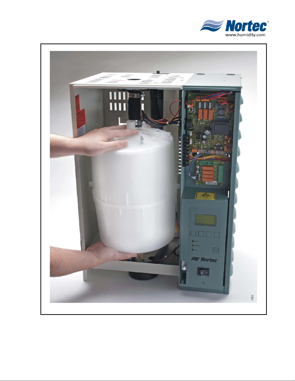
Figure 1. NHTC
10-00
Page 2
2008-08-28
Page 10

1. PRE-INSTALLATION
A. RECEIVING & UNPACKING EQUIPMENT
(1) Check packing slip to ensure ALL material has been delivered.
(2) All material shortages are to be reported to NORTEC within 48 hours from receipt
of goods. NORTEC assumes no responsibility for any material shortages beyond
this period.
(3) Inspect shipping boxes for damage and note damages on shipping waybill
accordingly.
(4) After unpacking, inspect equipment for damage and if damage is found, notify the
shipper promptly.
(5) All NORTEC products are shipped on an FOB factory basis. Any and all damage,
breakage or loss claims are to be made directly to the shipping company.
2. PACKAGING
A. GENERAL
(1) The equipment packaging is standardized in that each box in the shipment will
always have the same contents. The following paragraphs identify the contents of
each box.
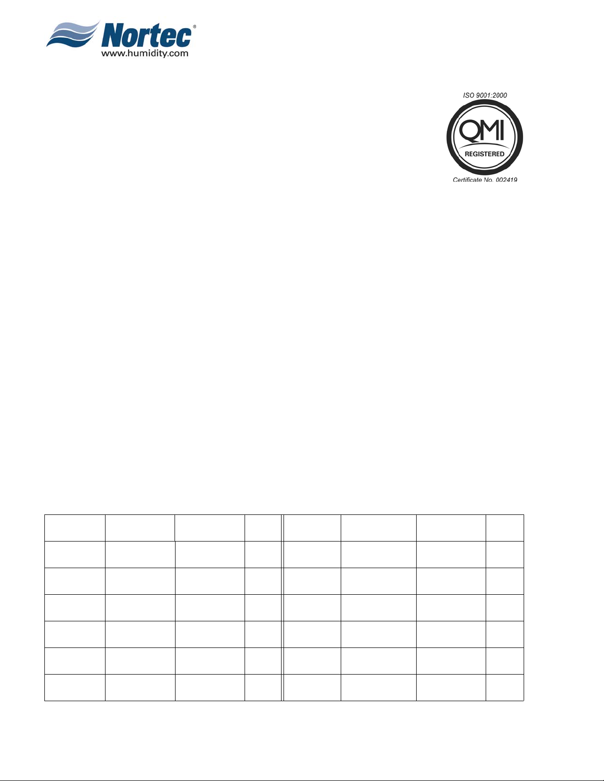
B. HUMIDIFIER AND CONTROLS BOX
(1) The typical equipment found in the humidifier and controls box is shown in Figure
2. The contents of the box are listed on the box. If controls are ordered they will be
listed and small accessories that fit into the box will also be listed on the box.
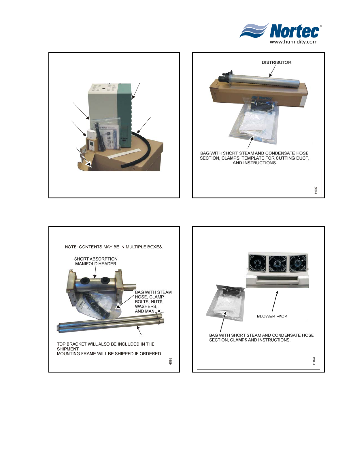
C. DISTRIBUTOR BOX
(1) Depending on the equipment ordered any of the following distributor box
configurations may be received:
a. For equipment received if an ASD, BSD, CSD distributor(s) is ordered refer to
Figure 3.
b. For equipment received if a SAM-e distributor is ordered refer to Figure 4.
c. For equipment received if a RMBP i s ordered refer to Figure 5.
D. ACCESSORIES BOX
(1) Additional accessories such as DWC, DWSP, Filter, and Fill cup extension kits are
shipped in a separate box. Smaller accessories that would fit in the humidifier box
are put in the humidifier box and the box is identified as containing such.
10-00
Page 3
2008-08-28
Page 11
BAG WITH
MANUAL,
CLAMPS,
HOSE SECTION
CONTROLS
(IF ORDERED
ONLY)
BOX WITH
ABBREVIATED
INSTRUCTIONS
AND BOX
CONTENT
STICKERS
Figure 2. Humidifier Box
HUMIDIFIER
STEAM HOSE
SECTION (NOT
SUPPLIED IF BUILT
ON BLOWER PACK
ORDERED)
H096
Figure 3. Distributor Box
Figure 4. SAM-e Distributor Box
Figure 5. Remote Mounted Blower Pack Box
10-00
Page 4
2008-08-28
Page 12

3. PREINSTALLATION EQUIPMENT VERIFICATION
A. GENERAL
(1) Ensure that available voltage and phase corresponds with humidifier voltage and
phase as indicated on humidifier’s specification label.
(2) Ensure that the dedicated external fuse disconnect is of sufficient size to handle
the rated amps as indicated on the specification label. Refer to local codes.
(3) Report any discrepancy immediately to the site engineer.
(4) Location and mounting is described in Chapter 10-10.
(5) Typical installation (See Figure 6.) shows the references to the appropriate
chapter of the manual.
10-00
Page 5
2008-08-28
Page 13
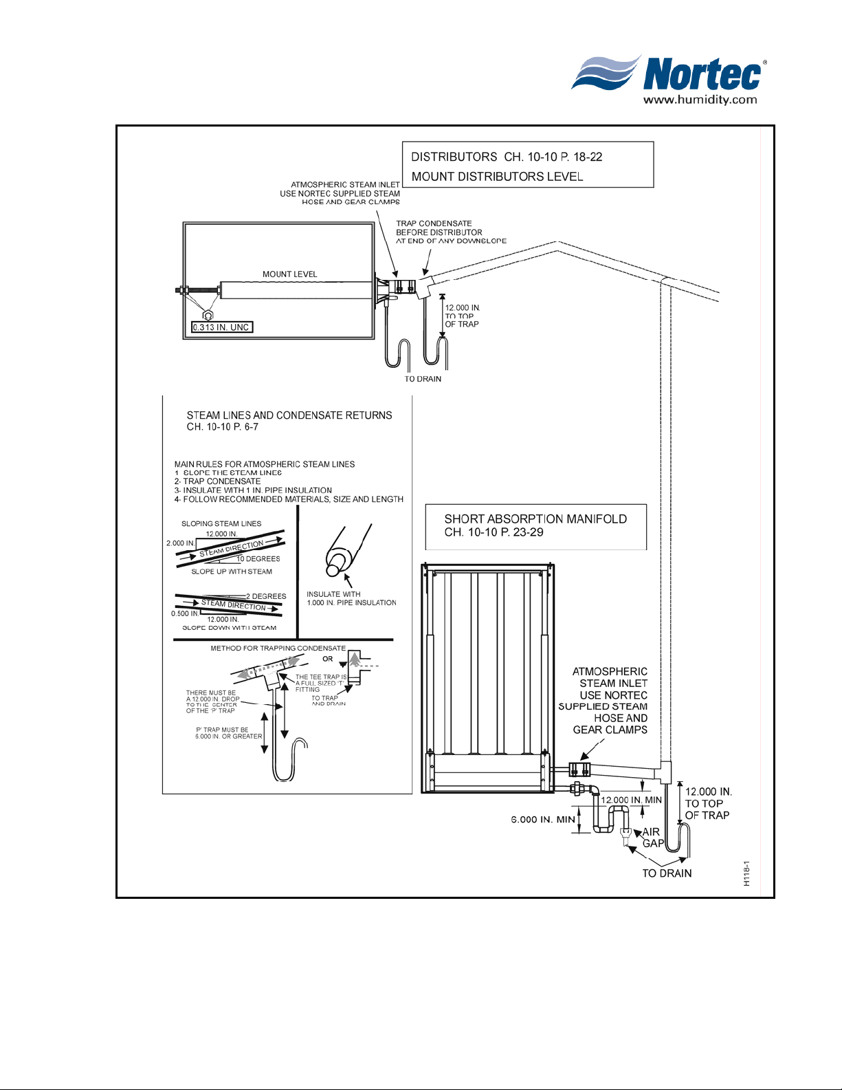
Figure 6. Typical NHTC Installation (Sheet 1 of 2)
10-00
Page 6
2008-08-28
Page 14
10-00
Page 7
2008-08-28
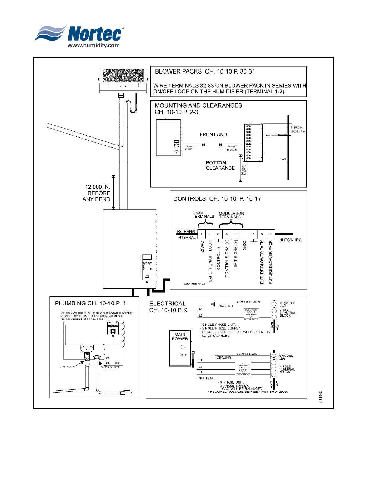
Figure 7. Typical NHTC Installation (Sheet 2 of 2)
Page 15

THIS PAGE INTENTIONALLY LEFT BLANK
10-00
Page 8
2008-08-28
Page 16

10-10
INSTALLATION
10-10
Page 9
2008-08-28
Page 17

1. HUMIDIFIER INSTALLATION
A. LOCATION
(1) The NORTEC NHTC series humidifier is designed to mount on a suitable wall or
vertical surface. Do not sit the unit on the floor due to clearances required for
plumbing and electrical connections. The clearance dimensions shown in this
manual are for reference only and are the minimum required for maintenance on
the humidifier. Local and national codes should be consulted before final location
and installation of the humidifier. NORTEC cannot accept responsibility for
installation code violations. See Figure 1 Clearances and Operating Conditions.
(2) The location of the humidifier should be below the steam distributor. DO NOT
locate the humidifier any further then absolutely necessary from the steam
distributor location as net output will be reduced as a result of heat loss through the
steam line.
(3) When possible, mount the NHTC humidifier at a height convenient for servicing.
B. MOUNTING WITH KEYHOLES
(1) The NHTC series humidifier is wall mounted using keyholes located on the back of
the unit’s cabinetry. The keyholes are spaced 16 inches apart center to center for
large units and 10.7 inches apart for small as per UL certification standard stud
spacing dictates.
(2) Use #12 x 3 in. screws. 2 screws are needed for a single unit (NHTC 010 to 100
lbs/hour). 3 screws are needed for a double unit (NHTC 150 to 200 lbs/hour). Insert
the screw 16 in. apart. Be sure the screws are level to each other. Proceed to
insert the screws into the studs until there is 1/4 in. of screw exposed. Ensure the
screws are properly anchored to the wall.
(3) Raise the unit. Align the keyholes on the back of the unit with the screws. Place the
screws through the keyholes. Make sure the unit is level then tighten the screws to
secure the unit in place.
(4) Once the unit is securely fixed to the wall, install the “L” shaped brackets into the
same studs the unit is attached to. Place the brackets on top of the unit, inline with
the studs. Using the appropriate sized wood screw fasten the “L” brackets to the
studs securing the unit from any upward motion. See Figure 2 Mounting with
keyhole.
C. MOUNTING WITH WALL BRACKET
(1) For NHTC units that mount using a Wall mounting bracket 3 x #12 3.0 inch wood
screws are to be used.
(2) Wall mounting bracket provided should be securely attached horizontally with open
edge upwards, using field-supplied fasteners. Be sure the bracket is mounted level
See Figure 3.
(3) If humidifiers are mounted on a roof, a thermostatically ventilated weather proof
cabinet should be used. Consult factory.
10-10
Page 10
2008-08-28
Page 18

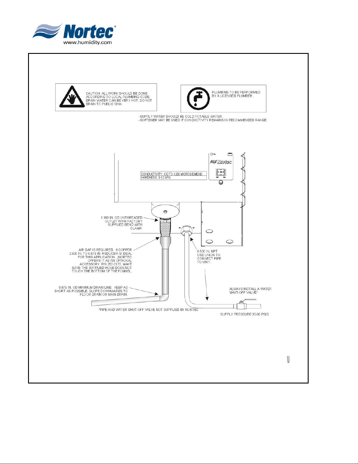
D. WATER SUPPLY LINE
(4) All water supply and drain line connections should be installed in accordance with
local plumbing codes.
(5) For installation details see Figure 5 & 6.
E. DRAIN LINE
DRAIN WATER FROM HUMIDIFIER CAN BE VERY HOT.
(1) The drain line should not end in a sink used frequently by personnel, or
where plumbing codes prohibit it. Route to a floor drain or equivalent for
safety reasons.
(2) For installation details see Figure 4.
F. STEAM RUNS AND CONDENSATE RETURNS
(1) Tables 1 through 6 indicate what material and recommended length to use when
installing atmospheric steam lines. The lengths mentioned are equivalent feet and
therefore the full length of tubing with the addition of equivalent feet of elbows and
tees.
CAUTION
(2) Figure 5 illustrates the guidelines for installation, routing and trapping of steam
runs and condensate returns.
(3) Table 6 indicates steam outlet size of humidifier and steam inlet size of distributors.
10-10
Page 11
2008-08-28
Page 19
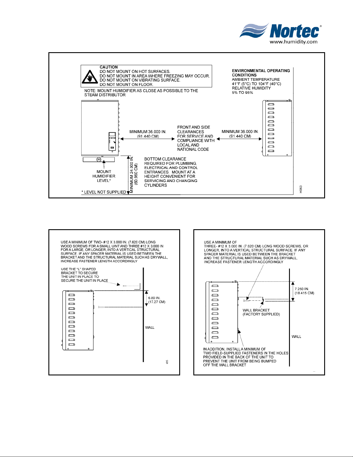
Figure 1. Clearances and Operating Conditions
Figure 2. Mounting with Keyholes
Figure 3. Mounting with Mounting Bracket
10-10
Page 12
2008-08-28
Page 20
10-10
Page 13
2008-08-28
Figure 4. Drain Water and Supply Connection
Page 21
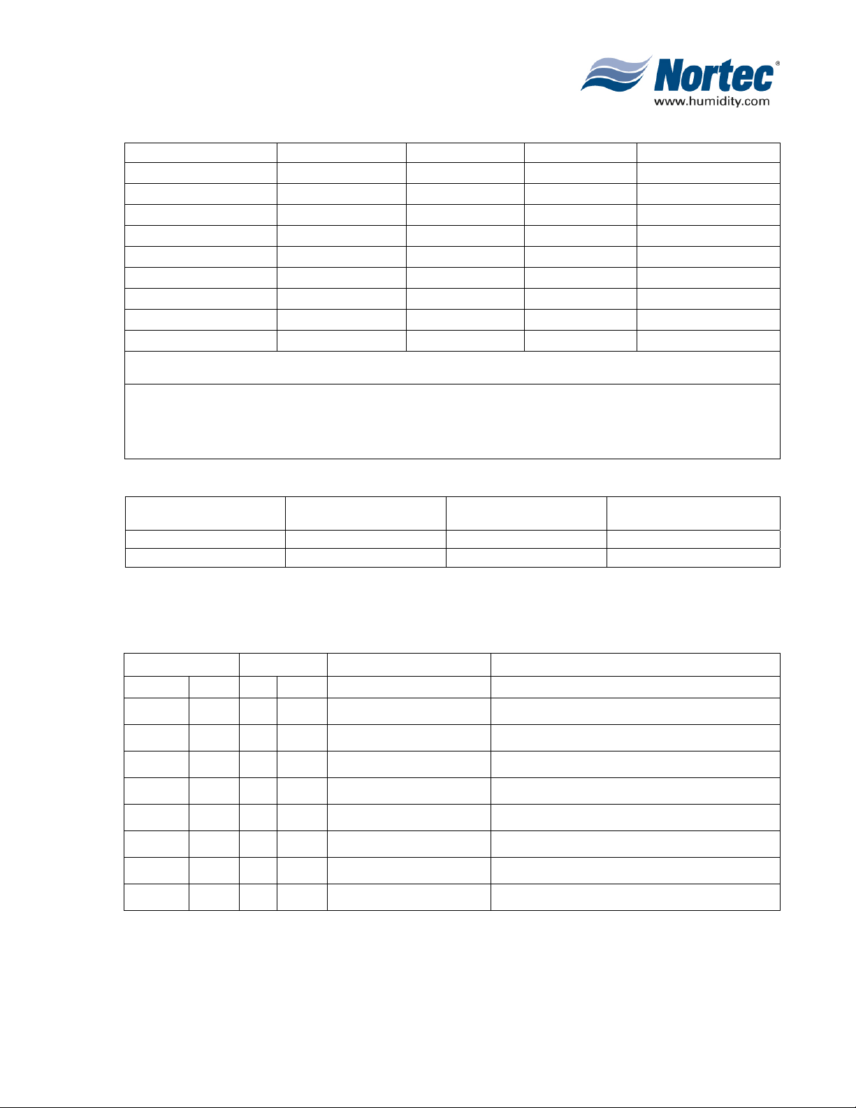
Table 1. Maximum Recommended Length of Steam Line
Unit Size Steam Output Distance Possible Loss Steam Line Size
NH-005 5 lbs/hr 8 feet 1.0 lbs/hr 3/4
NH-010 10 lbs/hr 15 feet 1.5 lbs/hr 3/4
NH-020 20 lbs/hr 20 feet * 2.0 lbs/hr 3/4
NH-030 30 lbs/hr 25 feet * 2.5 lbs/hr 3/4
NH-050 50 lbs/hr 40 feet ** 4.0 lbs/hr 1 ½”
NH-075 75 lbs/hr 50 feet ** 5.0 to 10.0 lbs/hr 1 ½”
NH-100 100 lbs/hr 50 feet ** 5.0 to 10.0 lbs/hr 1 ½”
NH-150 150 lbs/hr 50ft/cylinder ** 5.0 to 10.0 lbs/hr 1 ½” cyl
NH-200 200 lbs/hr 50ft/cylinder ** 5.0 to 10.0 lbs/hr 1 ½” cyl
* Use one inch copper steam line for longer runs.
** Use two inch copper steam line for longer runs.
Notes: 1. This table gives the maximum recommended steam run by unit size.
2. The use of steam line other then copper, stainless steel tube or Nortec supplied steam line will void the
warranty and may adversely effect the operation of the humidifier
3. The NH-150 and NH-200 are dual units.
Table 2. Steam Line Materials
NORTEC Steam Line Copper Tube (Potable)
Stainless Steel Tube
(RO or DI)
Short Run < 10 feet (3m) yes yes yes
Long Run > 10 feet (3m) no yes yes
NOTE
Do not use plastic, steel, or black iron. Long runs affect accuracy of humidifier and its ability to quickly
respond to changes in demand when tight control is required.
Table 3. Recommended Materials and Sizes for Steam Runs
Unit Size
lbs/hr kg/hr ft m
Steam Run Steam Line Material Steam Line Description
0-30 0-13 0-10 0-3 Copper Tube 0.750 in MED-L Tubing (0.875 inch OD)
0-30 0-13 30+ 3+ Copper Tube 1.0 inch MED-L Tubing (1.125 inch OD)
0-30 0-13 0-10 0-3 Stainless Steel Tube 0.875 inch Tube x 0.049 inch thick
0-30 0-13 30+ 3+ Stainless Steel Tube 1.125 inch Tube x 0.049 inch thick
50-100 22-45 0-20 0-6 Copper Tube 1.500 in MED-L Tubing (1.625 inch OD)
50-100 22-45 20+ 6+ Copper Tube 2.0 inch MED-L Tubing (2.125 inch OD)
50-100 22-45 0-20 0-6 Stainless Steel Tube 1.750 inch Tube x 0.065 inch thick
50-100 22-45 20+ 6+ Stainless Steel Tube 2 inch Tube x 0.065 inch thick
NOTE
Options show in bold-italic font require that reducers be used at both ends. These extra large sizes are
to allow for better condensation removal in long steam runs. These sizes do not permit the use of hose
couplings to connect either humidifier or distributors.
Insulate steam lines with 1” pipe insulation.
10-10
Page 14
2008-08-28
Page 22
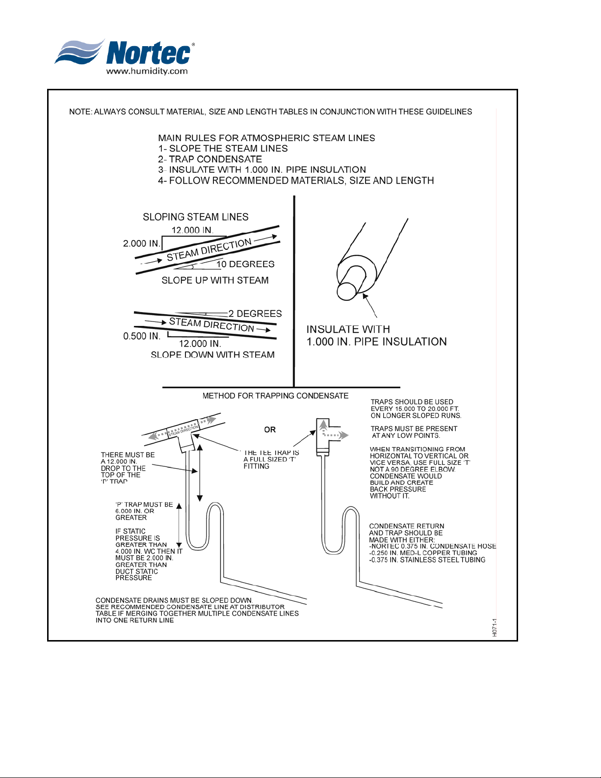
Figure 5. Steam Run and Condensate Return Installation Guidelines (Sheet 1 of 2)
10-10
Page 15
2008-08-28
Page 23
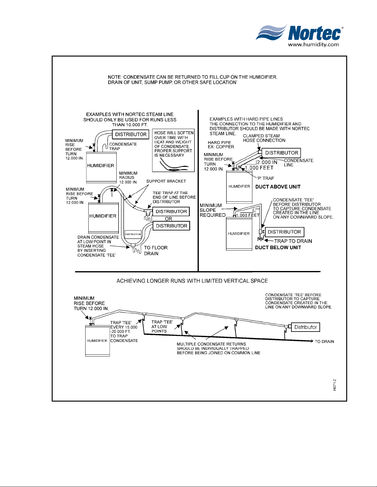
Figure 6. Steam Run and Condensate Return Installation Guidelines (Sheet 1 of 2)
2008-08-28
10-10
Page 16
Page 24
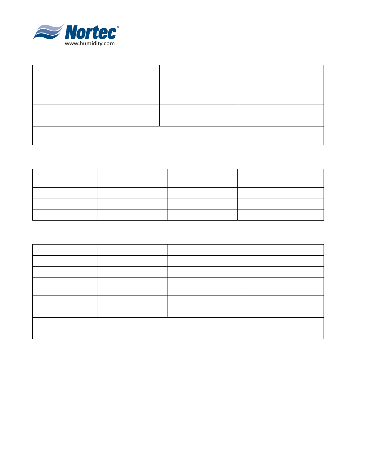
Table 4. Recommended Condensate Line at Distributor(s)
Dispersion Method Condensate Hose Copper Tube (Potable)
1 x Steam Distributor
0.375 inch
NORTEC 132-8840
0.375 inch
3 x Steam Distributor
NORTEC 132-8840
Note: *When using more then 1 steam distributor, the condensate line must be trapped before it is
joined together. See figure 4
0.250 inch. MED-L Tubing
(0.375 inch OD)
0.500 inch. MED-L Tubing
(0.875 inch OD)
Stainless Steel Tube
(RO or DI)
0.375 Tube 0.049 inch thick
0.650 Tube 0.049 inch thick
Table 5. Equivalent Lengths of Elbows and Tee Fittings
Nominal Tube
Diameter
0.750 / 0.875 in. 2 ft. 1 ft. 4 ft.
1.500 / 1.750 in. 3 ft. 6 in. 1ft. 9 in. 7 ft.
2.000 / 2.500 in. 4 ft. 6 in. 2 ft. 3 in. 10 ft.
Standard 90degree
Elbow
Standard 45 degree
Elbow Side Outlet Tee
Table 6. Humidifier and Distributor Inlet/Outlet Sizes
Humidifier Steam Outlet Distributor Steam Inlet
NH 5-30 0.875 in. OD ASD, BSD 0.875 inch OD
NH 50-100 1.75 in. OD CSD 1.75 inch OD
NH 150-200 Two 1.75 in. OD
SAM-e 1.75 inch OD*
mini SAM-e 0.875 or 1.75 inch OD**
NOTE: * SAM-e may have multiple 1.75 in. inlets depending on order.
** mini SAM-e inlet is determined on order and may have two 1.75 in. OD inlets.
Blower Pack
0.875 inch OD or
1.75 inch OD
10-10
Page 17
2008-08-28
Page 25
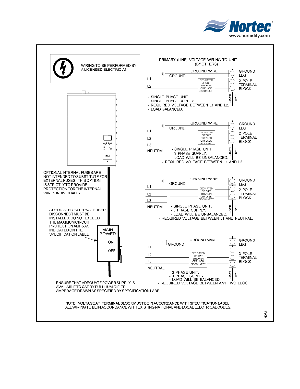
Figure 7. Primary Voltage Supply Wiring
10-10
Page 18
2008-08-28
Page 26

A
T
G. ELECTRICAL
(1) Primary Voltage Supply Wiring to Humidifier
(a) Local electrical codes should always be followed when installing a NORTEC
Humidifier. Direct wiring to the high voltage terminal is shown in Figure 7.
H. CONTROL WIRING
(1) Controls are available from NORTEC as accessories. If controls were not ordered
with humidifier, they must be purchased or supplied by others. The following
information is relevant to all controls, factory supplied or otherwise.
(a) On-Off Controls
CAUTION
REGARDLESS OF SELECTING ON/OFF OR MODULATING CONTROL
METHOD, NORTEC HUMIDIFIERS MUST HAVE A CLOSED CIR CUIT
CROSS ITS ON/OFF SECURITY LOOP CONTROL TERMINAL TO
OPERATE. NORTEC HIGHLY RECOMMENDS THE USE OF A HIGH
LIMIT HUMIDISTAT AND AN AIR PROVING SWITCH IN SERIES FOR
HIS FUNCTION.
The method and guidelines for installing on/off controls are displayed in
Figure 8. It can be combined with all control methods.
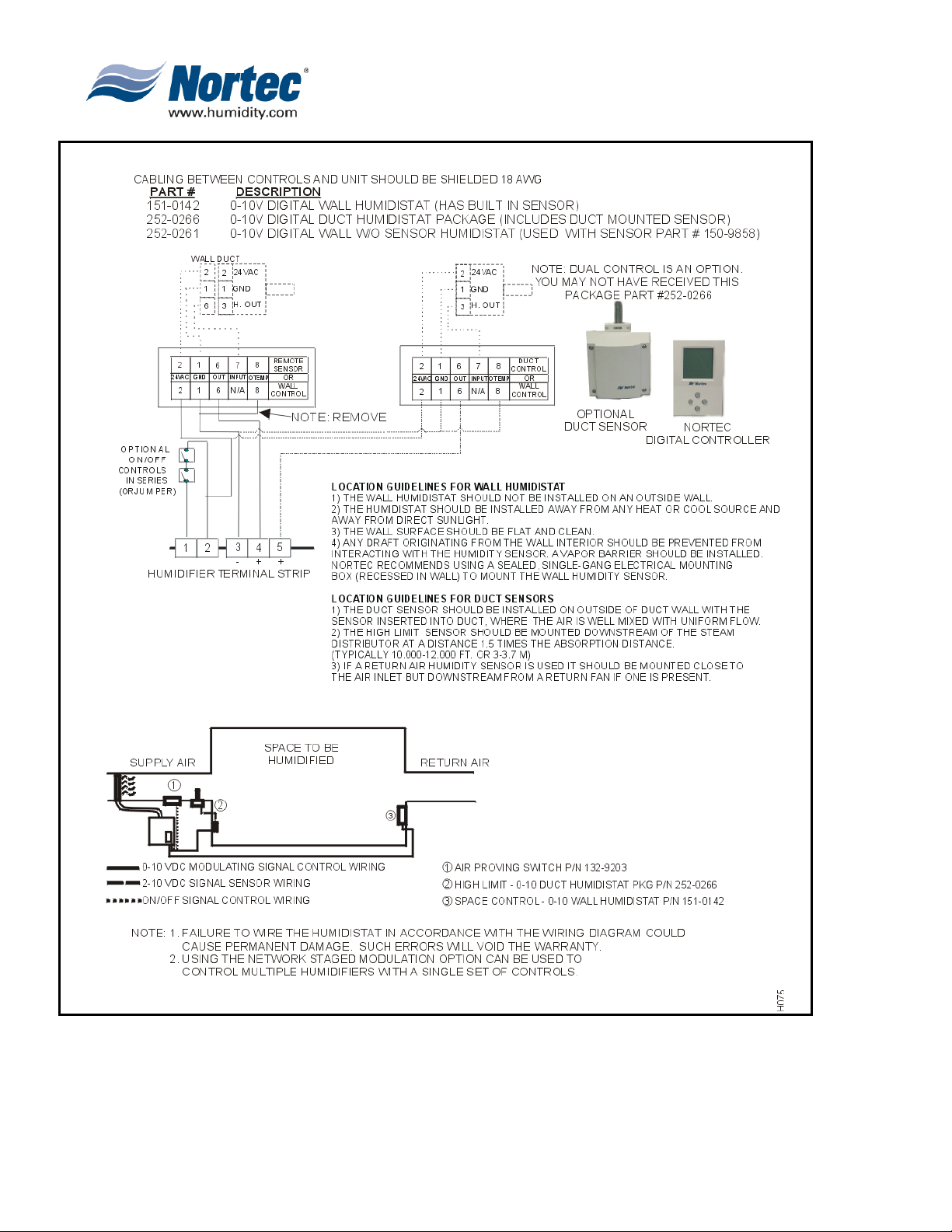
(b) Demand Signal Controls Installation
Figure 9 uses the Nortec optional Controllers to demonstrate the typical
demand signal installation.
10-10
Page 19
2008-08-28
Page 27
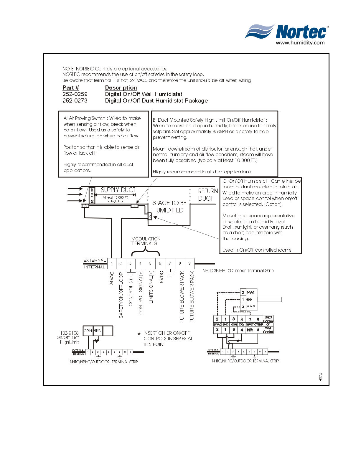
Figure 8.
On/Off Control Guidelines and Low Voltage Terminal Strip
10-10
Page 20
2008-08-28
Page 28
10-10
Page 21
2008-08-28
Figure 9. NORTEC Control Guidelines and Wiring (Optional)
Page 29

I. OPTIONAL OUTDOOR TEMPERATURE RESET FUNCTION
NOTE
Order outdoor temperature sensor separately, Part #252-0263.
(1) Each humidistat and controller is equipped with an integrated reset function that
will limit the setpoint during cold weather operation. This will prevent condensation
on windows and building structures. Figure 10 illustrates how the setpoint reset
feature operates.
(2) This feature is enabled by removing the jumper from terminals 8 and 1 on the
humidistat and wiring the outdoor temperature sensor to these terminals.
(3) When the outdoor temperature setback feature is in effect, the humidistat will
normally display the calculated setpoint limit based on the outdoor air temperature.
A snowflake will also be displayed to indicate cold weather operation. When any
key on the controller is pressed, the LCD screen will display the customer specified
setpoint for a short duration.
Figure 10. Setpoint Versus Outdoor Temperature
10-10
Page 22
2008-08-28
Page 30

J. HUMIDITY TRANSDUCER SIGNAL INSTALLATION
(1) Figure 11 displays the NORTEC optional humidity transducer installation.
K. NETWORKING NHTC
(1) The wiring of master/slave networks are explained in Figure 12. It allows operation
of multiple NHTCs with one control signal.
L. NORTEC ONLINE INSTALLATION
(1) An abbreviated recommended installation of NORTEC OnLine and its components
are shown in Figure 13.
10-10
Page 23
2008-08-28
Page 31

Figure 11. NORTEC Humidity Transducer Guidelines and Wiring (Optional)
10-10
Page 24
2008-08-28
Page 32

10-10
Page 25
2008-08-28
Figure 12. Networking NHTCs (Optional)
Page 33

Figure 13. NORTEC OnLine Installation Guidelines (Optional)
10-10
Page 26
2008-08-28
Page 34

10-20
OPERATION
10-20
Page 27
2008-08-28
Page 35

1. NHTC
A. NHTC COMPONENTS
(1) Refer to Figures 1 and 2 when reading Table 1.
B. HUMIDIFIER START-UP
(1) Figure 3 describes the method for powering up a humidifier and the cautions to take.
C. BASIC STEAM PRODUCTION METHOD
(1) Figure 6 describes the method the NH Series humidifier uses to produce pure clean
steam. The NORTEC NH electrode steam humidifier uses NORTEC’s patented AutoAdaptive cycle to calculate drains to maintain optimal performance. Figure 4 Drain Rate
vs Water Conductivity depicts an indication of drain amounts.
D. CYLINDER LIFE
(1) The output of all NH Series humidifiers is pure, clean steam; minerals originally in the
incoming water are left behind. These minerals will eventually coat the cylinder
electrodes. Therefore, the mineral content of the incoming water, the unit running time
and output capacity setting ultimately determine cylinder life. NORTEC’s cylinder life is
up to 2,000 hours of operation. Water chemistry and capacity can affect cylinder life.
(See Figure 5.) See Table 4 to identify the message which indicates when the cylinder
is at the end of its life.
Figure 1. NHTC Components (Front View)
Figure 2. NHTC Components (Side View)
10-20
Page 28
2008-08-28
Page 36

Table 1. NHTC/NHPC Components
Item Number Component Name Description
1 Steam Connector Used to allow easy replacement of cylinders without disconnecting
the steam line.
2 Condensate Return This inlet is to return condensate to the unit.
3 Fill Cup The fill cup allows isolation from the fill line by supplying an air gap.
It will also overflow any water that cannot enter the cylinder to drain.
4 Float Chamber (Optional) Detection OPTION – Used with the advanced foam detection
setting.
5 Manual Drain Button By pushing this button, manual drain is initiated with software
support. Software support supplies drain cooling if enabled and will
disable manual drain after 10 minutes.
6 Door Interlock The door interlock prevents the unit from running when the front
door is off. For startup and troubleshooting, pulling this interlock will
overide this safety feature.
7 Back-up Drain Back-up drain switch allows the draining of the cylinder without
electronic support.
8 Fill Valve The fill valve allows water to flow up to the fill cup. In units with
Drain Water Cooling to 120 degrees option, this valve is a dual
valve. The second valve is wired in parrallel with the drain valve to
quench the water with fresh cold water everytime the drain is
activated.
9 Drain Canal The drain canal allows all drainable water to accumulate into one
location to then be drained away.
10 Drain Valve Drain valve when energized will allow water to flow down to the
drain canal. When not energized, water flowing from the fill cup will
flow up into the cylinder.
1 1 Transformer The transformer converts the primary supply voltage to the required
24 VAC to the unit electronics. It is protected by a fuse to ensure
that the 24 VAC electronics are protected from surges or shorts.
12 On/Off Switch Turns the unit power on and off. Be aware that high voltage will still
enter the unit even though the 24VAC electronic are disabled. The
contactor will not be energized. Main shut-off should be open before
any servicing is performed.
13 Graphical Display and Menu
Buttons
14 Remote Relay Board (Optional) The remote relay board is a set of 4 dry contacts, rated for 24 VAC
15 NORTEC Cylinder The NOR T EC disposable cylinder contains electrodes that become
The graphical display and buttons are used to navigate through the
software. Use software flowchart as a reference.
1A, which activate in conjunction with humidifier on, steam
production, service and error conditions.
energized when the contactor is closed. This allows current to pass
through the water from one electrode to another, generating heat
within the water. The water then boils and the output is clean pure
steam.
10-20
Page 29
2008-08-28
Page 37

Table 1. NHTC/NHPC Components (cont)
Item Number Component Name Description
17 Cylinder Plug Cylinder plugs are press fit on cylinder electrode pins. These color
coded connections should fit snuggly, on same color pins. Replace
if loose or frayed.
18 Low Voltage T erminal Strip The low voltage terminal strip is the location at which all controls are
connected. See Installation for details.
19 Driver Board The driver board(s) is the housing of all fuses and relays. It is
connected to the total controller, and monitor and activate all
humidifier states.
20 Contactor The contactor(s) when energized allow main power to energize the
cylinder electrodes, allowing current to pass, boiling the water.
21 NORTEC OnLine Module
(Optional)
NORTEC ONLINE OPTION NHTC ONLY. This module allows the
NHTC to be connected to the internet and communicate information
to NORTEC via the internet. See NORTEC OnLine operation for
details. NHTC only
22 Links Module
(Optional)
23 Network Terminal Strip The network terminal strip allows up to 13 NHTC units to be
24 Fuse Holder OPTIONAL FUSE PACKAGE provides protection of individual high
25 High Voltage Terminal Strip Connection point of main power lines to the humidifier from the
26 Total Controller The total controller board (hidden in this view) is part of the
NORTEC LINKS OPTION NHTC ONLY This module allows the
NHTC to communicate with a BMS system using the
communication protocol requested at order. See NORTEC Links
operation for details. NHTC only
connected on one Links module and eight OnLine modules. See
Installation of NORTEC Links and OnLine for details on wiring
humidifier networks.
voltage lines in the humidifier and does not replace fuse and
external disconnect.
underside of the strip. It is accompanied by a ground terminal which
grounds the cabinet.
graphical display. It is the microcomputer that sends and collects
information from the driver boards, network modules and any other
humidifier connected to it.
10-20
Page 30
2008-08-28
Page 38

Figure 3. Humidifier Start-Up
10-20
Page 31
2008-08-28
Figure 5. Capacity Setting and Cylinder LifeFigure 4. Drain Rate Versus Water
Conductivity
Page 39

Figure 6. Basic Steam Production Method
10-20
Page 32
2008-08-28
Page 40

E. SOFTWARE INITIAL SELF-TEST
Table 2. Self-Test Messages
Graphic Display Explanation/Comments (What You Read)
NHTC START-UP:
INIT CYLINDER
NHTC START-UP:
READING CYLINDER DATA
SELF TEST CYLINDER
Inlet V a lve
ESC
SELF TEST CYLINDER
Drain Valve
ESC
SELF TEST CYLINDER
Heat Cont.
ESC
SELF TEST CYLINDER
Pump
ESC
SELF TEST CYLINDER
Bleed Valve
ESC
SELF TEST REMOTE
Steam Relay
ESC
SELF TEST REMOTE
Service Relay
ESC
SELF TEST REMOTE
Error Relay
ESC
SELF TEST REMOTE
Oper. Relay
ESC
The unit is beginning its bootup routine, along with powering up the EEPROM on the
SMART Cylinder
The unit reads the type of cylinder to provide maximum control of operation. If it
unable to do so it will skip the rest of the self-test and fault out.
Unit energizes the fill valve for 1 second.
Unit energizes the drain valve for 2 seconds.
Unit closes the contactor for 2 seconds.
Unit activates the pump (if present) for 2 seconds.
Unit activates the bleed valve (if present) for 2 seconds.
Unit activates the steam relay for remote fault indication package and green light.
Unit activates the service relay for remote fault indication package and yellow light.
Unit activates the error relay for remote fault indication package and red light.
Unit activates the unit on relay.
F. SOFTWARE FLOW CHART WITH DEFINITIONS
(1) The flow chart in Figure 7 depicts the software logic and definitions.
G. SELF-HELP
(1) The microcomputer applies corrective actions whenever its self-diagnostics identifies a
problem that it is able to correct by itself. If the corrective action is not successful then
it displays a system message. If the corrective action requires a service person, then
the microcomputer’s only resort is to stop the unit and display a system message. The
unit never stops unless it has to.
(2) After three days of no call from either the on/off controls or the modulating controls,
when active, the three-day drain active feature is automatically activated long enough
to drain all water from the steam cylinder. This NORTEC feature will prolong the life of
the cylinder. (User selectable, default is ON.)
10-20
Page 33
2008-08-28
Page 41

Figure 7. Software Flow Chart (Sheet 1 of 7)
10-20
Page 34
2008-08-28
Page 42

10-20
Page 35
2008-08-28
Figure 7. Software Flow Chart (Sheet 2 of 7)
Page 43

Figure 7. Software Flow Chart (Sheet 3 of 7)
10-20
Page 36
2008-08-28
Page 44

10-20
Page 37
2008-08-28
Figure 7. Software Flow Chart (Sheet 4 of 7)
Page 45

Figure 7. Software Flow Chart (Sheet 5 of 7)
10-20
Page 38
2008-08-28
Page 46

10-20
Page 39
2008-08-28
Figure 7. Software Flow Chart (Sheet 6 of 7)
Page 47

Figure 7. Software Flow Chart (Sheet 7 of 7)
10-20
Page 40
2008-08-28
Page 48

H. SYSTEM MESSAGES AND LIGHTS
(1) Table 3 describes general signal light status meanings.
Table 3. Signal Light Status
Yellow Green Red
OFF OFF OFF Unit is on standby or humidifier has just been energized but has not sensed
production of steam yet.
OFF ON OFF Humidifier senses production of steam.
ON OFF OFF An attention state exists that should not prevent the unit from producing steam
when the controls call for it. Check the message on the screen to try to correct it.
ON ON OFF Prepare to replace cylinder or normal startup operation. May also indicate an
attention during operation. Check the message on the screen to try to correct it.
BLINK OFF OFF Manual Drain On with software drain switch.
OFF BLINK OFF Unit sees a demand, but safeties are open.
OFF OFF ON Operation fault (unit will not run).
(2) Table 4 describes common status messages and the lights displayed for each and their
meaning. For a list of warnings and faults, see Chapter 10-40 Troubleshooting.
I. DOUBLE UNIT OPERATION
(1) The unit will report only one cylinder at a time if the unit was ordered without coupled
circuits. You will notice on the screen the indication of which cylinder you are
monitoring and in the lower right the option to monitor the alternate cylinder.
10-20
Page 41
2008-08-28
Page 49

Table 4. Status Messages with LED State
NHTC Display Message LED state System Action
Idle None Unit is made idle.
Humidifying GRN (after steam
production starts)
MANUAL DRAIN: ON YEL (blink) The drain valve is activated.
SAFETY LOOP; OPEN GRN
(blink)
LEVEL SENSOR; ON None Deactivates the fill valve to prevent overfilling.
KEEP WARM ACTIVATED None Keep Warm feature activated, it has closed the
The unit has closed the contactor and is sending
current to the cylinder to humidify.
Steam production stopped.
contactor to warm the water.
W19: Cylinder spent YEL, GRN The electronics allow the cylinder to be reset up
to four times before locking out the humidifier.
E19: Cylinder spent YEL, RED Humidifier interrupts operation and the fault relay
is activated.
FOAM: FULL TANK FLUSHING None The unit will initiate a flush of the cylinder and
resume operation.
10-20
Page 42
2008-08-28
Page 50

Symptom Diagnosed Probable Cause Corrective Action
Unit is awaiting a demand or
control signal.
This is normal when there is no need for
humidity. If you believe there is a need for
humidity, and the unit should not be idle,
refer to troubleshooting
Normal Operation
The unit is now boiling water in
the cylinder and filling as
necessary.
This is not a fault or warning. It
is an indication that the manual
drain switch has been activated.
Safety loop circuit (terminal 1
and 2) is open.
Water has reached the top of
the cylinder and has activated
the high water sensor. This is
not an error or fault, but is
normal on start-up and at the
end of a cylinder life span.
Keep Warm feature is enabled
and proceeding to a Keep Warm
Cycle.
This is normal when there is a need for
humidity. If you believe there is no need for
humidity, and the unit should idle, refer to
troubleshooting
Manual drain switch has been activated. Press Manual Drain button again to
One or more of the safety devices is open
as the result of a device failure, improper
installation or an unsafe condition has been
detected.
1. Normal on start-up with a new cylinder
or a cylinder that has been completely
drained because of an extended off
period. This condition can last several
hours until the water in the cylinder has
concentrated or the electrodes can no
longer provide rated capacity or
adjusted capacity. Water level
automatically rises to meet the demand.
2. Foaming can also cause an invalid high
water indication.
Unit is entering the Keep Warm cycle. The
unit has been inactive for a given period
and is keeping the water warm.
Normal Operation
stop the drain action.
Determine which device is preventing
continuity of the safety loop circuit, and
verify that it is functioning properly and
is properly installed and calibrated.
If foaming is determined to be the
cause of the high water indication,
consult your local representative about
possible adjustment and/or a foam
detection kit. If not foaming, consider it
normal operation unless water level is
not at the top of the cylinder.
Normal for unit with Keep Warm setting
activated.
Electronics have determined
cylinder is spent. Within the next
72 hours the humidifier will stop.
Electronics have determined
that the cylinder is spent.
The electronics has detected
foaming within the cylinder (only
for units with the optional Foam
Detection Package).
10-20
Page 43
2008-08-28
The cylinder must be replaced with the
same type and model.
The cylinder must be replaced with the
same type and model.
The unit has detected a foaming condition
within the cylinder.
When ordering a new cylinder, quote
the model number presently installed in
the humidifier.
When ordering a new cylinder, quote
the model number presently installed in
the humidifier.
The unit will initiate corrective action on
its own.
Page 51

2. STEAM DISTRIBUTION
A. STEAM DISTRIBUTOR OPERATION
(1) Figure 8 describes the method by which the steam distributor releases pure clean
steam into the duct while collecting condensate and removing it by the condensate
return.
B. SAM-e OPERATION
(1) Figure 9 describes the method by which the Short Absorption Manifold releases pure
clean steam into the duct while collecting condensate, removing it by condensate
return and ensuring short absorption distance.
C. BLOWER PACK OPERATION
DURING AND FOLLOWING OPERATION OF THE HUMIDIFIER, THE
STEAM AND COMPONENTS IN CONTACT WITH THE STEAM ON THE
BLOWER PACK CAN BECOME HOT AND CAN BURN IF TOUCHED.
(1) Figure 10 describes the method by which the blower pack distributes the pure clean
steam directly into the space required. It also describes the adjustments that can be
made to conform to the specific situation.
WARNING
Figure 8. Steam Distributor Operation
10-20
Page 44
2008-08-28
Page 52

Figure 9. SAM-e Operation
10-20
Page 45
2008-08-28
Figure 10. Blower Pack Operation and Adjustments
Page 53

3. CONTROLS AND REMOTE COMMUNICATION (OPTIONAL)
A. DIGITAL CONTROL OPERATION
(1) Figure 11 shows the components of the NORTEC Controller and how to adjust the
setpoint.
(2) In the case of a modulating NORTEC Controller, Figure 12 shows the relation between
the difference from setpoint to %rh in the room and the 0-10 V DC demand signal sent
out. From this basis the NORTEC Controller uses its PI algorithm to adjust its demand
signal in accordance with the history of the environment. This type of control allows for
tighter and more precise control.
B. DIGITAL TRANSDUCER OPERATION
(1) The NORTEC digital transducers, shown in Figure 13, are designed to sense humidity
in duct or in room respectively, and report it back to a controller or the NHTC directly.
Required humidifier output is determined by controller or humidifier.
C. REMOTE CONNECTIONS (OPTIONAL)
CAUTION
NORTEC DOES NOT RECOMMEND USING THE DRY RELAY
CONTACTS WITH ANYTHING MORE THAN 24 VAC, 1 AMP.
(1) The NHTC reports the signal light status, in Table 3, by closing the supplied dry contact
relays which can be wired back to a BMS or monitoring station. This method of
monitoring is not as informative as the actual display, but alerts you to the general
status of the unit.
Figure 11. NORTEC Digital Controller
10-20
Page 46
2008-08-28
Page 54

D. NORTEC LINKS 2 OPERATION
(1) NORTEC LINKS 2 is an option that can be integrated with the NHTC. This allows a
BMS to monitor and in the right configuration, control the humidifier. For additional
information about NORTEC Links and its operation and configuration, go to
www.humidity.com
(2) Table 5 contains a list of NORTEC LINKS 2 variable definitions. For a complete list,
contact the factory.
E. NORTEC ONLINE OPERATION
(1) NORTEC OnLine is an option that can be integrated with the NHTC. This allows a user
to log onto the internet, go to www.norteconline.com
their unit from any computer with an internet connection. (See Figure 14)
(2) After initially logging into the NORTEC OnLine server the user will be presented with a
list of humidifiers currently registered with the Server program. Each humidifier will be
listed with a unit type identifier, a serial number and an address descriptor.
(3) By clicking on the humidifier name, the user will then be brought to a status screen with
an image of the selected humidifier.
(4) Figure 14 shows a typical NORTEC OnLine Monitoring Screen. Use this manual in
combination with NORTEC OnLine to be able to monitor and understand the settings
possible through the NORTEC OnLine Interface.
and look up the NORTEC LINKS 2 manual.
and log in to allow them to monitor
Figure 12. Difference from Setpoint in
Relation to Demand Signal
10-20
Page 47
2008-08-28
Figure 13. Duct and Wall Mounted
Transducer
Page 55

THIS PAGE INTENTIONALLY LEFT BLANK
10-20
Page 48
2008-08-28
Page 56

10-30
MAINTENANCE
PROCEDURES
10-30
Page 49
2008-08-28
Page 57

MAINTENANCE PROCEDURES
1. NH ELECTRODE STEAM HUMIDIFIERS
Typical tools required for any maintenance procedure:
- Slotted Screwdriver
- Small Slotted Screwdriver
- Phillips Screwdriver
- Needle-Nose Pliers
- Wrench
A. MAINTENANCE
WARNING
DISCONNECT MAIN POWER BEFORE ANY SERVICING.
WARNING
THE PLUMBING AND ELECTRICAL COMPARTMENTS CONTAIN HIGH
VOLTAGE COMPONENTS AND WIRING. ACCESS SHOULD BE
LIMITED TO AUTHORIZED PERSONNEL ONLY.
(1) The NHTC and its components are a very low maintenance system. The only
maintenance normally required is to change the cylinder, clean out the drain valve
assembly, clean out the inlet valve screen and know the procedure for extended shutdown and start-up.
B. WHEN TO REPLACE THE STEAM CYLINDER
(1) The steam cylinder is disposable and must be replaced at end of cylinder life. Cylinder
life is dependent on water supply conditions and humidifier usage. Failure to replace
the cylinder at the end of cylinder life will cause the unit to lock out. NORTEC is not
responsible for any damages resulting from, or attributed to, the failure to replace a
spent cylinder (see Manufacturer’s Warranty). There are many indications, each of
which signifies the end of cylinder life. See 10-20 Operation, Table 4, for details on how
the unit functions and determines end of cylinder life.
C. EXTENDED SHUT-DOWN
(1) As long as the NHTC is powered, it will automatically drain the cylinder when there has
not been a call for humidity for an extended period of time. This feature will reduce or
prevent the possibility of corrosion of the electrodes and the accumulation of algae and
bacteria growing in the cylinder. The cylinder will remain empty until there is a call for
humidity at which time the fill valve will open and refill the cylinder. The unit will go
through its normal process for optimum operation.
(2) Should it be required to disconnect power to the humidifier for a period of extended
shut-down, always drain the cylinder first. Leave the switch in the OFF position and
‘open’ the main external fused disconnect to stop power to the humidifier. Close the
shut-off valve in the water supply line feeding the humidifier.
10-30
Page 50
2008-08-28
Page 58

D. COMPONENTS OF THE STEAM CYLINDER
(1) Consult Figure 1 for NORTEC cylinder components.
10-30
Page 51
2008-08-28
Figure 1. Cylinder Components
Page 59

E. HOW TO REMOVE THE STEAM CYLINDER
(1) Consult Figure 2 for removal of the steam cylinder.
Figure 2. Cylinder Removal Procedure
10-30
Page 52
2008-08-28
Page 60

F. MANDATORY CLEANING OF THE DRAIN VALVE
(1) Always clean the drain valve before installing a new cylinder since the valve port may
be as dirty as the used cylinder. Figure 3 describes the process of removing and
cleaning the drain valve. Perform paragraph E. before proceeding.
10-30
Page 53
2008-08-28
Figure 3. Drain Valve Maintenance
Page 61

G. HOW TO INSTALL THE REPLACEMENT CYLINDER
(1) Consult Figure 4 to install the replacement cylinder.
Figure 4. Cylinder Replacement Procedure
10-30
Page 54
2008-08-28
Page 62

10-40
TROUBLESHOOTING
10-40
Page 55
2008-08-28
Page 63

1. TROUBLESHOOTING NH ELECTRODE STEAM HUMIDIFIERS
A. PREPARATION
(1) Ensure the installation detail conform to installation requirements.
(2) Understanding the Principle of Operation and the software menus is an asset when
troubleshooting. This information is found in chapter 10-20 Operation and can be
elaborated on by your local representative.
(3) When contacting your local representative or NORTEC for troubleshooting assistance,
please ensure the serial number has been obtained for reference purposes.
(4) Whenever the troubleshooting steps indicate a problem with the main pc-board, first
check all connections at the main PCB (including the ribbon cable connections at the
center of the main PCB) before ordering replacements.
B. STARTING POINT
(1) Table 1 checkpoints will allow for faster troubleshooting. Ensuring that all these steps
are taken is good practice when beginning to troubleshoot the NH series humidifier.
Check your symptom and verify all points before ordering any replacement parts or
contacting your local representative. Use the wiring diagram when necessary for
clarification.
NOTE
Wiring diagrams on unit supersedes diagrams in this manual.
WARNING
BE AWARE, WHEN TROUBLESHOOTING, THAT THE HUMIDIFIER IS
POWERED BY HIGH VOLTAGE AND FAMILIARITY WITH BOTH GOOD
PRACTICES AND WIRING OF THE HUMIDIFIER IS RECOMMENDED.
ANY TROUBLESHOOTING THAT REQUIRES OPENING THE CABINET
SHOULD BE DONE BY QUALIFIED PERSONNEL.
C. NHTC/NHPC
(1) The self-diagnostic system built into the NHTC is continually checking the status of the
electrical circuits to the fill valve, drain valve, primary voltage contactor, high water
sensor and steam cylinder. The modulating signals from external humidistat and
reduced manual capacity settings are taken into consideration. When problem
symptoms are found, the NHTC/NHPC will take self-corrective actions, if applicable. It
will, if necessary, respond by shutting itself down. Table 3 describes some of the
conditions the NH unit can detect and warn or protect itself against. Table 4 contains a
definition of the terms used in this section.
10-40
Page 56
2008-08-28
Page 64

System What to Check Why
Nothing is happening when the
on/off switch is turned on
Table 1. Troubleshooting Symptoms
Main power is on and matches the
specified voltage on the specification label.
No, or improper voltage can cause the
electronics or components not to respond.
The unit will not fill or fills very
slowly (less then 1” per minute)
24 VAC output from the step-down
transformer. Check high and low voltage.
Ensure that fuses in the humidifier and on
the electronic boards are good. Ensure
that 24 VAC is getting to the main board.
Door interlock open. The door interlock has malfunctioned.
Water supply is on and water pressure is
between 30 to 80 psig
Unit is getting a demand signal or the unit
is producing the required steam capacity.
See ensuring demand T able 2.
No leak at drain valve or around cylinder.
Check for water coming out of the drain.
Check the fill valve inlet.
Check fill valve strainer.
Check optional inline filter.
24 VAC is required to power nearly all the
components of the humidifier, including the
electronics.
The fuses are in place to prevent damage
to the electronics. If there was a surge the
fuse may have blown to prevent damage
to the unit.
The proper water volume and pressure
must be available as the valves in the NH
unit rely on its pressure to control volume
and operation. NORTEC recommends 55
to 60 PSIG.
The unit will not activate the fill valve
without a demand for humidity. It will also
only fill as necessary once there is a
demand. Once it reaches the requested
demand, it will stop filling.
The cylinder is held in by gravity and
sealed by an O-ring. If not properly seated,
it could leak and prevent the unit from
filling.
Drain stuck open
Unit will not humidify or is not
reaching requested capacity.
Unit has faulted or has a
warning
10-40
Page 57
2008-08-28
Pressure in the steam line could also
prevent filling causing the water in the fill
cup to overflow to drain.
Strainer is clogged.
Fill valve may also be restricted after
capturing debris in its filter.
Unit is getting a demand signal. Refer to
Table 2.
Capacity is manually limited. The unit will not surpass the capacity
Cylinder is full. The unit will not fill further than a full
Check Table 3, Faults and Warning Codes Each code is identified and each has
Unit will not send power to the cylinder
without a demand and safeties met.
dictated by the user in the software.
cylinder. Operation requires it to try to
concentrate the conductivity, which may
take several hours, before it reaches full
capacity.
individual causes and solutions.
Page 65

Table 2. Ensuring A Demand Signal
Check Why and How
Safety Loop (terminal 1
and 2) is closed
Channel 1 has a signal. Whether for on/off or modulating, a voltage potential signal must be present between
Channel 2 has a signal Only applicabl e if configured to accept dual channel input.
The safety loop is checked to ensure that it is safe to operate. Checking to see 24 VAC from
terminal 1 to ground, and terminal 2 to ground should indicate whether is closed.
If found to be open, isolate which component in the safety loop is open to solve the issue. If
suspect, confirm that it is connected and operating properly.
terminal 3 and 4 for the humidifier temperature.
If on/off there should be 5 VDC.
If VDC modulating, at least 25% of total possible signal must be present.
If mA controlled, at least 25% of total possible signal must be present.
If Transducer signals, the unit setpoint must be higher then the sensed room RH signal.
If VDC modulating, at least 25% of total possible signal must be present.
If mA controlled, at least 25% of total possible signal must be present.
If Transducer signals, the high limit setpoint must be higher than the sensed RH signal.
2. TROUBLESHOOTING DISTRIBUTORS
CAUTION
KEEP IN MIND WHEN TROUBLESHOOTING DISTRIBUTORS THAT
THEY ARE BEING USED WITH STEAM AND THEREFORE, ARE AND
CAN REMAIN VERY HOT DURING THE TROUBLESHOOTING
PROCESS.
A. TROUBLESHOOTING ATMOSPHERIC DISTRIBUTORS
(1) If the distributor is spitting out water, ensure that the distributor is installed level and
check the condensate return for proper slope, check head above the trap, and check
the trap that it is clear of obstructions.
(2) If the distributor is condensing inside the duct, make sure the installation clearances
are as indicated in Chapter 10-10 Installation, and make sure that the design conditions
have not changed. If over humidification of the duct results, check controls and safeties
(ensure safeties are properly installed and functioning).
3. SAM-e TROUBLESHOOTING
A. PROCEDURE
(1) If the SAM-e is spitting out water, ensure that the distributor is installed per instructions
in Chapter 10-10 Installation and check the condensate return for proper slope and trap
and that it is clear of obstructions. The condensate return must be the lowest point of
the SAM-e header.
10-40
Page 58
2008-08-28
Page 66

(2) If the SAM-e is condensing inside the duct, make sure that the design conditions have
not changed.
(3) If grommets leak, make sure the tubes are firmly inserted, if cracks or damage are
found, replace grommet.
4. BLOWER PACKS TROUBLESHOOTING
A. PROCEDURE
(1) An optional blower pack (BP), ensure power supplied to blower pack either from
humidifier or other source, if present, gets its primary voltage from inside the humidifier.
This way, only one external power source has to be connected to the equipment.
Confirm this power source before troubleshooting the blower pack.
(2) Ensure blower pack is installed per Chapter 10-10 Installation.
(3) If fans are not functioning, confirm safety is not open. Fans are only ON when steam is
being discharged.
5. DIGITAL ON/OFF HUMIDISTAT SENSOR CALIBRATION
A. PROCEDURE
(1) The humidity sensor is factory calibrated, however, it can be field recalibrated.
(a) The calibration routine can be accessed by pressing and holding down the option
button for five seconds. A new screen will appear with the calibration adjustments.
(b) Press the up or down buttons until the text calH appears on the LCD screen.
(c) To adjust the calibration press the Option button. The screen should load to
display the current calibration trim. The calibration trim can be adjusted by
pressing the up or down buttons to the desired level and then pressing the option
button to confirm the settings.
(d) Press the Power button to return to the normal display.
NOTE
A properly calibrated hygrometer should be used in conjunction with any calibration
procedure.
10-40
Page 59
2008-08-28
Page 67

Table 3. NH System Messages
NHTC Display Message LED state System Action Symptom Diagnosed
E5: Cylinder B Controller
missing
E6: Extendet Missing RED Humidifier activates its fault
E7: CPU CRC fault RED Humidifier activates its fault
W11: Safety Loop Open GRN Humidifier goes on standby. O N/OFF controls wired between
W12: Cylinder Max Level NONE Fill valve inte rrupted. Water at top of cylinder.
E12: Cylinder max Level no
current
W13: Fill Timeout GRN
RED Humidifier is in standby until
problem corrected.
relay and interrupts its operation
until communication is fixed.
relay and interrupts operation.
RED Humidifier activates its fault
relay and interrupts its
operation.
The humidifier will attempt to
blink
clear any debris by pulsing the
drain valve.
On power up, the controller cannot
detect the driver board for cylinder B.
The slave unit is not in communication
with the master unit. Master unit
powered?
Problem with the processor hardware
or software.
terminal 1 and 2 are open.
The high water sensor is activated but
no current is measured in cylinder.
The fill valve has been activated for an
extended period of time but water has
not reached the sensor.
E13: Fill: Timeout RED The fill valve has been activated
for an extended period of time
but has not reached the sensor.
W15: Over current YEL The drain is activated to
decrease the water level in the
cylinder.
E15: Over Current RED Humidifier interrupts operation
and the fault relay is activated.
W16: Excess Current YEL Humidifier interrupts operation
and the fault relay is activated.
E16: Excess Current RED Humidifier interrupts operation
and the fault relay is activated.
Humidifier stops operation and the
fault relay is activated.
Measured current in the cylinder has
exceeded 115% of rated output.
Measured current in the cylinder has
exceeded 115% of rated output.
Measured current in the cylinder has
exceeded 115% of rated output.
Measured current in the cylinder has
exceeded 130% of rated output.
10-40
Page 60
2008-08-28
Page 68

Probable Cause Corrective Action
1. The driver board is damaged.
2. Controller is not configured correctly.
1. The master unit is not configured correctly.
2. Is the RJ12 cable damaged?
3. Is an incorrect RJ12 cable used?
4. J2 ports on driver boards are not connected.
The electronics of the main PCB have diagnosed the main
PCB (itself) as defective.
1. Current measurement core loose on driver board?
2. Primary wire not looped through CT core?
3. High water sensor plug is on an electrode pin.
1. Is the drain stuck open?
2. Check system backpressure.
3. Is the water supply closed?
4. Drain leaking?
1. Is the water supply closed?
2. Is the drain leaking?
3. Check the system backpressure.
1. Is the drain blocked?
2. Is the cylinder filling too fast?
3. Was the wrong fill valve supplied?
4. Is there scale in the cylinder?
5. Is the water too conductive?
6. Is the wrong cylinder supplied?
7. Is the cylinder spent?
1. Replace the driver board.
2. Verify that the humidifier is a double unit.
3. Check that the driver board ribbon cable is connected
to the main board.
1. Verify configuration settings for the units.
2. Replace the RJ12 cable.
3. Replace with correct cable.
4. Check all connections to the processor board.
Reset humidifier and monitor display. If Error reoccurs
within one minute of resetting the unit, the problem is with
the main PCB. If the Error is not repeated, the primary
power to the unit is suspect.
1. Connect CT core.
2. Interrupt main power and rewire CT core.
3. Install high water plug on shrouded pin.
1. Clean drain valve or replace.
2. Install fill cup extension kit if required.
3. Open water supply.
4. Clean drain valve.
1. Open water supply.
2. Clean drain valve.
3. Clean drain valve or replace.
4. Install fill cup extension kit if required.
1. Clean the drain line.
2. Replace the fill valve.
3. Replace the fill valve.
4. Rinse the cylinder.
5. Change water supply.
6. Install the correct type of cylinder.
7. Replace the cylinder.
1. Is the drain blocked?
2. Is the drain restricted?
3. Is the cylinder filling too fast?
4. Was the wrong fill valve supplied?
5. Is there scale in the cylinder?
6. Is the water too conductive?
7. Was the wrong cylinder supplied?
1. Is the drain blocked?
2. Is the drain restricted?
3. Is the cylinder filling too fast?
4. Was the wrong fill valve supplied?
5. Is there scale in the cylinder?
6. Is the water too conductive?
1. Is the drain blocked?
2. Is the drain restricted?
3. Is the cylinder filling too fast?
4. Was the wrong fill valve supplied?
5. Is there scale in the cylinder?
6. Is the water too conductive?
10-40
Page 61
2008-08-28
1. Clean the drain line.
2. Clean the drain line.
3. Replace the fill valve.
4. Replace the fill valve.
5. Rinse the cylinder.
6. Change the water supply.
7. Install correct cylinder type.
1. Clean the drain line.
2. Clean the drain line.
3. Replace the fill valve.
4. Replace the fill valve.
5. Rinse the cylinder.
6. Change the water supply.
1. Clean the drain line.
2. Clean the drain line.
3. Replace the fill valve.
4. Replace the fill valve.
5. Rinse the cylinder.
6. Change the water supply.
Page 69

Table 3. NH System Messages (cont)
NHTC Display Message LED state System Action Symptom Diagnosed
E17: Req off current RED Humidifier interrupts operation
and the fault relay is activated.
W18: Foam YEL System will activate selected
foam algorithm. (See Figure 7.)
E18: Foam RED System will activate selected
foam algorithm. (See Figure 7.)
W19: Cylinder spent YEL T he electronics allow the
cylinder to be reset up to four
times before locking out the
humidifier.
E19: Cylinder spent YEL, RED Humidifier interrupts operation
and the fault relay is activated.
W20: Conductivity too low YEL Humid ifier will continue to
operate on this water supply.
W23: Control sensor broken YEL Humidifier put on standby. After
a timeout period, this warning
becomes a fault.
With no system demand, current is
detected in the cylinder.
System has detected foaming and will
attempt to self correct if foam mode is
active.
System has detected foaming and will
attempt to self correct if foam mode is
active.
Electronics have determined cylinder
is spent. Within the next 72 hours the
humidifier will stop.
Electronics have determined that the
cylinder is spent.
Water conductivity is determined to be
less than optimum.
Electronics cannot detect the control
RH sensor connected to the
humidifier.
E23: Control sensor broken RED Humidifier interrupts operation
and the fault relay is activated.
W24: Limit sensor broken YEL Humidifier put on standby. After
a timeout period, this warning
becomes a fault.
E24: Limit sensor broken RED Humidifier interrupts operation
and the fault relay is activated.
W25: 3-day idle drain
activated
W26: 3-day forced drain
activated
YEL The humidifier drains the
cylinder after three days of
inactivity.
YEL The humidifier drains the
cylinder after three days of
operation.
Electronics cannot detect the control
RH sensor connected to the
humidifier.
Electronics cannot detect the limit RH
sensor connected to the humidifier.
Electronics cannot detect the limit RH
sensor connected to the humidifier.
This safety feature drains standing
water.
This customer selected feature drains
the cylinder to remove minerals.
10-40
Page 62
2008-08-28
Page 70

Probable Cause Corrective Action
1. Is the contactor closed but not energized?
2. Does the processor board display capacity output but
contactor is open?
1. Back pressure?
2. Organics present in water?
3. Insufficient drain or over concentration.
1. Back pressure?
2. Organics present in water?
3. Insufficient drain or over concentration.
The cylinder must be replaced with the same type and
model.
The cylinder must be replaced with the same type and
model.
1. Is the drain leaking?
2. Adjust drain factor.
3. Check the system backpressure.
4. Is salt required?
1. Is the sensor powered?
2. Is the sensor wiring correct?
3. Is the sensor defective?
4. Is the RH less than 5%?
1. Is the sensor powered?
2. Is the sensor wiring correct?
3. Is the sensor defective?
4. Is the RH less than 5%?
1. Replace the contactor.
2. Replace the driver board.
1. Verify drain is functioning and clean.
2. Verify steam line installation.
3. Check optional inline filter.
1. Verify drain is functioning and clean.
2. Verify steam line installation.
3. Check optional inline filter.
When ordering a new cylinder, quote the model number of
cylinder presently installed in the humidifier or serial
number of humidifier.
When ordering a new cylinder, quote the model number
presently installed in the humidifier.
1. Clean the drain valve.
2. Set drain factor to 0.7.
3. Install a fill cup extension kit if required.
4. Add one teaspoon of table salt.
1. Use a multimeter to check that the sensor is powered.
2. Verify wiring is correct as per wiring instructions.
3. Replace the sensor.
4. RH values under 5% are interpreted as a broken
sensor.
1. Use a multimeter to check that the sensor is powered.
2. Verify wiring is correct as per wiring instructions.
3. Replace the sensor.
4. RH values under 5% are interpreted as a broken
sensor.
1. Is the sensor powered?
2. Is the sensor wiring correct?
3. Is the sensor defective?
4. Is the RH less than 5%?
1. Is the sensor powered?
2. Is the sensor wiring correct?
3. Is the sensor defective?
4. Is the RH is less than 5%?
--- To disable this feature, consult the programming manual
--- To disable this feature, consult the programming manual
1. Use a multimeter to check that the sensor is powered.
2. Verify wiring is correct as per wiring instructions.
3. Replace the sensor.
4. RH values under 5% are interpreted as a broken
sensor.
1. Use a multimeter to check that the sensor is powered.
2. Verify wiring is correct as per wiring instructions.
3. Replace the sensor.
4. RH values under 5% are interpreted as a broken
sensor.
shipped with the humidifier.
shipped with the humidifier.
10-40
Page 63
2008-08-28
Page 71

Table 3. NH System Messages (cont)
NHTC Display Message LED state System Action Symptom Diagnosed
W27: Safety loop instability YEL The safety loop is interrupting
humidifier operation.
A security control is causing the safety
loop to switch on and off too rapidly.
W28: demand signal instability YEL The demand signal is swinging
from low demand to high
demand too quickly.
W29: limit signal instability YEL The limit signal is swinging from
low demand to high demand too
quickly and the humidifier
cannot respond.
W30: Modbus remote disable YEL The humidifier is being
controlled via the network, not
locally.
W43: Keep warm active YEL This is a customer selectable
feature to keep the cylinder
water warm.
W44: Demand signal short
cycling
W45: safety loop short cycling YEL The cylinder automatically
W46: RH high warning YEL An alarm indication is
W47: RH low warning YEL The humidifier is operating and
W49: wrong cylinder installed YEL An alarm indication is
E50: Modbus Timeout RED Systems shuts down. Time window for Modbus has elapsed.
YEL The cylinder automatically
reduces the humidifier output to
stabilize operation.
reduces the humidifier output to
stabilize operation.
generated.
an alarm indication is
generated.
generated.
The demand signal is unstable.
The limit signal is unstable.
The humidifier has been disabled by a
network message.
The humidifier is in standby mode.
The cylinder may energize at any
time.
The demand signal is cycling on and
off too frequently.
The demand signal is cycling on and
off too frequently.
RH levels higher than the limit set
have been detected. The humidifier
should not be operational with this
warning activated.
RH levels lower than the limit set have
been detected. The humidifier should
be operational with this warning
activated.
The cylinder installed is not the
recognized type for the humidifier.
10-40
Page 64
2008-08-28
Page 72

Probable Cause Corrective Action
1. The high limit is too close to the distributor.
2. Is there loose wiring?
3. Are there defective controls?
4. Is the safety high limit set point is too low?
1. The high limit is too close to the distributor.
2. Is the controller defective?
3. Are the P and I settings incorrect?
1. The high limit is located too close to the distributor.
2. Is the controller defective?
3. Are the P and I settings incorrect?
4. Safety high limit set point is set too low.
--- Contact the system administrator to override the remote
--- To disable this feature, consult the programming manual
1. Is the humidifier oversized?
2. Check the sensor location.
3. Are the P and I settings incorrect?
1. Is the humidifier oversized?
2. Is the high limit located too close to the distributor?
3. Are the safety controls damaged?
1. Is the humidifier still operating?
2. Is the humidifier oversized?
1. Relocate high limit 10 feet from the steam
distributor.
2. Check all wires at the safety controls.
3. Replace any defective device.
4. Change high limit set point to 85% or more.
1. Relocate high limit 10 feet from the steam
distributor.
2. Replace the controller.
3. Adjust the P and I constants.
1. Relocate high limit 10 feet from the steam
distributor.
2. Replace the controller.
3. Adjust the P and I constants.
4. Change high limit set point to 85% or more.
command.
shipped with the humidifier.
1. Reduce manual capacity setting by 50%.
2. The sensor should be located away from doors and
drafts.
3. Adjust the P and I constants.
1. Reduce manual capacity setting by 50%.
2. Relocate the high limit to 10 feet from the steam
distributor.
3. Replace any damaged controls.
1. Verify that the RH setpoint is less than the RH high limit
setting.
2. Reduce the manual capacity setting by 50%.
1. Is the humidifier still operational?
2. Is the humidifier oversized?
--- Verify that the replacement cylinder is the same as the old
1. Loose wire.
2. Electronics damaged.
3. Electromagnetic Interference.
1. Verify that the RH setpoint is greater than the RH low
limit setting.
2. Set the manual capacity setting to 100%.
3. Add more humidifiers.
cylinder.
1. Verify cables.
2. Replace electronics or contact factory.
10-40
Page 65
2008-08-28
Page 73

Table 4. Term Definitions
Term Definition
RATED AMPS Re fers to amps listed on the humidifier specification label.
SHORT CYCLING When the ‘on time’ of the humidifier is less than ten minutes upon a call for humidity. To correct
short cycling, all humidifiers have a capacity adjustment which allows the output of the humidifier to
be reduced as low as 20% of rated output, thus extending the ‘on time’ required to maintain output.
FOAMING This phenomenon can occur in water when the impurities, already in the water, reach an excess
concentration as result of boiling away pure water, and the continued boiling action agitating the
contained water. The humidifier electronics are designed to prevent this occurrence, although in
extreme cases water will foam with little concentration making it necessary to have the drain time of
the water, contained in the cylinder, increased. Foaming is normally caused by short cycling, a
restricted drain, or back pressure. The foam generated in these instances, is conductive and may
lead to a false full cylinder indication if the level of the foam approaches the top of the cylinder.
BACK PRESSURE This can be caused by restriction of steam flow caused by lo ng steam runs; improperly sloped
steam lines; elbows changing the direction of the steam flow from horizontal to vertical without a
drain leg, any plumbing detail allowing the accumulation of condensate; undersized steam line;
improper steam distributor; downward air flow onto the distributor creating excess static pressure at
the steam outlets; or high static pressure ducts (not probable). To overcome excess static pressure
in the duct, a fill cup extension kit should be used. In downflow applications, a downflow distributo r
should be used but in some cases the fill cup extension will also be required.
RESET UNIT
(HUMIDIFIER)
To reset the humidifier, the ON/OFF switch at the front of the humidifier should be switched to the
OFF position for a minimum of five seconds and then switched back to the ON position.
MONITORED LEG Refers to the primary wire to the cylinder which loops through the current sensing device on the
driver PCB. This wire is terminated at the red cylinder plug at the cylinder. Units with six primary
wires to the cylinder will monitor only one of the two wires, terminating with red plugs.
CONDENSATE Refers to steam that has condensed to a liquid.
6. 0-10V DIGITAL HUMIDISTAT SENSOR CALIBRATION
A. PROCEDURE
(1) The humidity sensor is factory calibrated, however, it can be field recalibrated. The
calibration routine can be accessed by pressing and holding down the option button for
five seconds. A new screen will appear with the calibration adjustments.
(a) Press the up or down buttons until calH appears on the LCD screen.
(b) To adjust the calibration press the Option button. The screen should load to
display the current calibration trim.
(c) The calibration trim can be adjusted by pressing the up or down buttons to the
desired level and then pressing the option button to confirm the settings.
(d) Press the Power button to return to the normal display.
10-40
Page 66
2008-08-28
Page 74

10-50
TECHNICAL
10-50
Page 67
2008-08-28
Page 75

1. WIRING AND TERMINALS
A. HUMIDIFIER CONTROL INFORMATION
(1) See Figure 7 and Figure 9 in Chapter 10-10 for Controller and Transducer terminal
definitions. See Figure 6 in Chapter 10-10 for low voltage terminal strip terminal
definitions.
Table 1. Controller and Sensor Specifications
Power Supply Operating Voltage 24 VAC ± 10%
50/60 Hz
Power Consumption Max. 3 VA
Internal Rectification Ha lf-wave rectified
Signal Inputs Analog Input
Input Signal
Resolution
Accuracy
Temperature Input
Range
Humidity Input:
Range
Accuracy
Repeatability
Signal Outputs Digital Outputs
Maximum Load
Environment Operation
Temperature
Humidity
Housing Materials Cover, back
Mounting Plate
AI1
2-10 VDC
39 mV, 0.078 mA
± 2%
External Thermistor
-40° to 140°C (-40° to 284°F)
0 to 100 %RH
± 3.0% at 25°C (77°F)
± 0.5%
DO1
24 VAC 2A max.
0° to 50°C(32° to 122°F)
<95%RH
Fire proof ABS plastic
Galvanized Steel
10-50
Page 68
2008-08-28
Page 76

B. NH WIRING
(1) See Figure 1and 2 for the NHTC/NHPC Single and Double Unit Wiring diagrams.
10-50
Page 69
2008-08-28
Figure 1. NHTC/NHPC Double Unit Wiring Diagram
Page 77

Figure 2. NHTC/NHPC Wiring Diagram
10-50
Page 70
2008-08-28
Page 78

2. CHECK LISTS
A. PRE-NORTEC ONLINE START UP CHECKLIST WIRING
(1) Humidifier-to-Humidifier
Connection:
Each individual Humidifier linked
to lead Unit.
(4) Start-Up Procedure:
Ensure power is being supplied
to the humidifier and Nortec
Online Module.
Connection can be direct or
daisy-chained to other units.
(2) Network Connection:
Lead Unit wired to Local Network
(Ethernet, GPRS, Dial-up).
Network activity verified.
(3) Controls Wired:
Directly to humidifiers.
B. PRE-NORTEC LINKS START-UP CHECKLIST
(1) Humidifier-to-Humidifier
Connection:
Each individual Humidifier linked
to lead Unit.
Connection can be direct or
daisy-chained to other units.
(2) Network Connection:
Lead Unit wired to Local BMS.
Network activity verified.
(3) Controls Wired:
Directly to humidifiers.
Verify power to NetBiter (Power
LED should be lit).
After power-up, verify network
communication.
Verify variable operation after
mapping is complete.
Perform regular humidifier
start-up check.
(4) Start-Up Procedure:
Verify power to NORTEC Links
module.
Verify power to I/O-Controller.
Adjust Network address dials to
desired address (BACnet/IP
address is preset at factory).
After power-up, verify network
communication.
Map desired network variables to
BMS.
Verify variable operation after
mapping is complete.
10-50
Page 71
2008-08-28
Perform regular humidifier start-
up check.
Page 79

C. HUMIDIFIER MANDATORY PRE-START UP CHECKLIST
Unit Serial #: _________________No. of humidifiers: _______ Tag: _______________
Unit type: _______ __________Voltage: _____V/___ph Steam output: ____lbs/hr
Customer/Job: ______________ Address: _____________________________
Inspected by: ________________Date of inspection: ____/____/____
WATER QUALITY:
Well water
Conductivity: _______ mhmos Hardness: _____ gr.
HUMIDIFIER MOUNTING:
Clearances around the unit Acceptable Obstruction
– Front (door opens freely?) 3 ft min. ______________________
– Top (steam lines) 2 ft min. ______________________
– Bottom (fill, drain, controls) 2 ft min. ______________________
– Right (main pwr) 2 ft min. ______________________
___ City water ___ Softened water ___ RO / DI water ___
STEAM LINES:
– Slope up 2 in. per 12 in.
– Slope down 0.500 in. per 12 in. ___
– Traps
– Insulated
– Length/Size _____/_______
– 90 degree elbows
– Can condensate be trapped anywhere in the steam line? yes
WATER LINES:
– 0.050 in. at max 4ft from the unit
– Water pressure: 30-80 psig ___ – PVC ___ – Stainless steel ___
DRAIN LINES:
– Air gap located within 3 ft of the unit
CYLINDER:
– Cylinder properly installed and sitting upright
WIRING:
– No loose wires around the unit or on the PC board? yes
___
___
___
___ qty: ____ – 45 degree Elbows ___ qty: ____
___– 3/8 in. connection at fill G
CONDENSATE LINES:
– Sloped back to drain
– Trapped 2 in. more than static
duct pressure
– Size _______
– St ain less steel
– ____% Vertical ____% Horizontal
___
___ or plastic ___
___ no ___
___ – Sloped to drain ___ – Size:________
___ no ___
___
CONTROLS:
Installed Location / Wiring /Setting Installed Location / Wiring /Setting
– High limit:
– Mod controller:
POWER:
– Voltage, amperage rating and fuse correspond to Spec Label:
– Disconnect switch located close to humidifier:
___ ____________________ – Air proving: ___ ____________________
___ ________________– Other: ___ ________________________
___
___
10-50
Page 72
2008-08-28
Page 80

D. HUMIDIFIER MANDATORY START-UP CHECKLIST AND QUICK REFERENCE
Unit Serial #: _________________No. of humidifiers: _______ Tag: _______________
Unit type: ___________________Voltage: _____V/___ph Steam output: ____lbs/hr
Customer/Job: ______________ Address: ______________________________________
Inspected by: ________________Date of inspection: ____/____/____
1. PRELIMINARY:
– Pre-start-up checklist completed? yes
If no, return to Pre-Start-up Checklist before going on with start-up procedure.
2. START-UP PROCEDURE:
The prerequisites for getting power and water into the steam cylinder are as follows:
– check that main breaker is on and power is at the unit.
– check that main water shut-off valve is open.
– on/off/drain switch must be switched on.
– control circuit 1-2 must be made.
– modulation humidistat, if present, must be calling.
– door interlock switch must be made (interlock switch can be pulled out to operate unit).
___ no ___
The unit will undergo a self-test to ensure integrity of all the components:
– NHTC Start-Up Unit Cylinder
– Reading Cylinder Data
– Inlet Valve
– Drain Valve
– Heat Controller
– Pump
– Bleed Valve
– Steam Relay
– Service Relay
– Error Relay
– Operation Relay
It will then start filling the cylinder and begins normal operation. Most water does not
contain enough conductivity for full boil on initial start-up. Units will need to concentrate
the water over a time period (hours to days).
Remarks:
__________________________________________________________________________
__________________________________________________________________________
__________________________________________________________________________
__________________________________________________________________________
10-50
Page 73
2008-08-28
Page 81

E. PERIODIC MAINTENANCE CHECKLIST AND QUICK REFERENCE (PAGE 1 OF 2)
Unit Serial #: _________________No. of humidifiers: _______ Tag: _______________
Unit type: ___________________Voltage: _____V/___ph Steam output: ____lbs/hr
Customer/Job: ______________ Address: ______________________________________
Inspected by: ________________Date of inspection: ____/____/____
WHEN TO REPLACE THE CYLINDER:
NHTC/NHPC light indication and LCD display:
1. Yellow and Green light with W19: Cylinder Spent indicates the cylinder must be
replaced in the next 72 hours.
2. Red and Yellow light with E19: Cylinder Spent indicates the cylinder is at the end of
its life and must be replaced.
CYLINDER REPLACEMENT PROCEDURE:
1. Turn off water supply to unit.
2. Activate drain to completely empty water content (less than 10 minutes)
3. When drained, stop drain and turn off unit.
4. Also open the main electrical disconnect switch and open plumbing.
5. Remove the cylinder plugs by pulling vertically. The plugs are press-fitted over the
electrode pins protruding from the top of the cylinder.
6. Using a slotted screwdriver, loosen the steam line clamp(s) and pull steam line off
the cylinder vertically.
7. Using a small slotted screwdriver, depress tab on the re-usable cable tie, if present,
around the middle of the cylinder. This will loosen the cable tie to come apart for reuse later on.
8. The cylinder is now ready to be removed from the unit.
CAUTION: Cylinder and any remaining water might still be HOT.
9. Always clean the drain valve before installing a new cylinder. (see further below)
10. Remove the used cylinder and replace by a new one. Do not re-use cylinder.
MANDATORY CLEANING OF THE DRAIN VALVE
1. Note that ring terminal for drain valve green ground wire is sandwiched between
drain valve body and drain pan.
2. Remove two screws securing drain valve body to drain pan. Disconnect the two
slip-on terminals from the two tabs on the (24 VAC) drain valve coil.
3. Remove hose clip and hose connection from drain valve body.
4. Drain valve assembly is now free to be taken to a sink for disassembly and cleaning.
Important: Tapered end of spring must be installed toward the solenoid.
5. Clean out the end of the hose, and then reconnect it to the drain valve body with the
clamp.
6. Fit mounting screws through drain valve body, one through ring terminal on green
ground wire.
WARNING: To prevent the possibility of electrical shock the green ground wire must be
reinstalled before power is restored. Push the two slip-on terminals back onto
the two tabs on the coil. The terminals, although not identical, are reversible.
10-50
Page 74
2008-08-28
Page 82

E. PERIODIC MAINTENANCE CHECKLIST AND QUICK REFERENCE (PAGE 2 OF 2)
Unit Serial #: _________________No. of humidifiers: _______ Tag: _______________
Unit type: ___________________Voltage: _____V/___ph Steam output: ____lbs/hr
Customer/Job: ______________ Address: ______________________________________
Inspected by: ________________Date of inspection: ____/____/____
HOW TO INSTALL THE REPLACEMENT CYLINDER
1. Reverse procedure should be followed to install new cylinder. Main disconnect is to
be left open until cylinder is completely installed and reconnected.
2. Ensure that the re-usable cable tie a nd mounting brackets, within the unit, secure the
cylinder properly.
3. The cylinder plug wires are colour-coded in accordance with coloured dots beside
the electrode pins on top of the cylinder.
4. This colour coding must be adhered to when replacing cylinder plugs on pins.
5. With cylinders having six primary vo ltage cylinder plugs, it should be noted that there
are two of each colour.
6. Care must be taken so that cylinder leads of the same color are always directly
opposite each other as indicated by the dot formation on the top of the cylinder.
7. The white cylinder plug on all units is for the high water sensor electrode, which
always goes on the single pin surrounded by a plastic shoulder.
8. Ensure that cylinder plugs fit snugly on the pins.
9. If cylinder plugs become loose, it is best to obtain a new replacement plug. Consult
factory.
EXTENDED SHUTDOWN:
1. Before disconnecting power to the humidifier for a period of extended shutdown,
ALWAYS DRAIN the cylinder first.
2. ‘Open’ the main external fused disconnect to stop power to the humidifier.
3. Close the shut-off valve in the water supply line feeding the humidifier.
ACCESS SHOULD BE LIMITED TO AUTHORIZED PERSONNEL ONLY.
4. NHTC 3 day drain: As long as the NHTC is powered, it will automatically drain the
cylinder when there has not been a call for humidity for an extended period of time.
5. The cylinder will remain empty until there is a call for humidity at which time the fill
valve will open and refill the cylinder.
This feature will reduce the possibility of corrosion of the electrodes and the possible
accumulation of algae and bacteria growing in the cylinder.
Remarks:
__________________________________________________________________________
__________________________________________________________________________
__________________________________________________________________________
__________________________________________________________________________
10-50
Page 75
2008-08-28
Page 83

3. SPARE PARTS AND EXPLODED VIEWS
A. ASD, BSD, CSD DISTRIBUTOR
(1) See Figure 3 for the ASD, BSD, CSD Distributor exploded view and spare parts.
Figure 3. Distributor Exploded View and Spare Parts
B. SAM-e SPARE PARTS
(1) See Figure 4 for the SAM-e exploded view and spare parts.
Figure 4. SAM-e Exploded View and Spare Parts
10-50
Page 76
2008-08-28
Page 84

C. NH SERIES HUMIDIFIER SPARE PARTS
(1) See Figure 5 for the NHTC/NHPC plumbing compartment exploded view and spare
parts and Table 2 for the parts list. See Figure 6 for the NHTC/NHPC electrical
compartment exploded view and spare parts and Table 3 for the parts list.
Figure 5. NHTC/NHPC Plumbing Compartment Exploded View and Spare Parts
10-50
Page 77
2008-08-28
Page 85

Table 2. NHTC/NHPC Plumbing Part List
SINGLE PHASE THREE PHASE
550-600/3
440-480/3
380/3
220-240/3
208/3
550-600/3
440-480/3
380/3
220-240/3
208/3
550-600/3
440-480/3
380/3
220-240/3
208/3
550-600/3
440-480/3
380/3
220-240/3
208/3
550-600/3
440-480/3
380/3
220-240/3
208/3
550-600/3
440-480/3
380/3
220-240/3
208/3
550-600/3
440-480/3
380/3
220-240/3
208/3
550-600/1
440-481/1
380/1
277/1
220-240/1
208/1
550-600/1
440-480/1
380/1
227/1
220-240/1
208/1
110-120
VOLTS/PH
PART NO.
MODEL 005 010 020 020 030 050 075 100 150 200
DESCRIPTION NORTEC
CYLINDER 201 X 150-9724
CYLINDER 202 X 150-9725 1 111
CYLINDER 203 X 150-9726 1
CYLINDER 204 X 150-9727 11
CYLINDER 321 X 150-9732 111
CYLINDER 305 X 150-9729 1
CYLINDER 309 X 150-9730 11
CYLINDER 311 X 150-9731 111
CYLINDER 303 X 150-9728 11
CYLINDER 331 X 150-9733
CYLINDER 333 X 150-9734
CYLINDER 421 X 150-9738 11
CYLINDER 407 X 150-9736 1
CYLINDER 411 X 150-9737 11
CYLINDER 621 X 150-9744 11 11 11 22 22
CYLINDER 603 X 150-9739 11122
CYLINDER 607 X 150-9741 11 11 1 22 2
CYLINDER 605 X 150-9740 12
CYLINDER 609 X 150-9742
CYLINDER 617 X 150-9743
CYLINDER 631 X 150-9745
CYLINDER 636 X 150-97462STEAM OUTLET, LARGE, NHTC ONLY 150-9465 1111111111111112222222222
STEAM OUTLET, SMALL, NHTC ONLY 150-9466 111111111111111111111113CLAMP FOR SMALL STEAM LINE 132-5007 2 2222222222222222222222
CLAMP FOR LARGE STEAM LINE 132-5009 2222222222222224444444444
NO.
ITEM
1
4 DRAIN CHANNEL 111-6857 1 11111111111111111111111111111111111112222222222
5 DRAIN CHANNEL GASKET 163-1026 1 11111111111111111111111111111111111112222222222
FILL CUP ASSEMBLY SMALL 252-2406 11111111111111111111111
FILL CUP ASSEMBLY LARGE 252-2407 1111111111111112222222222
SMALL STEAM LINE 0.875 IN. ID 9.000 IN. 132-8810 1111111
SMALL STEAM LINE 0.875 IN. ID 5.000 IN. 132-8810 11111111111
6 VALVE DRAIN 93BEIGE + 24V COIL 145-6000 111111111111111111111111111111111111112222222222
7 CYLINDER BRACKET 150-9593 111111111111111111111111111111111111112222222222
8
9
SMALL STEAM LINE 0.875 IN. ID 4.500 IN. 132-8820 11111
LARGE STEAM LINE 1.500 IN. ID 7.000 IN. 132-8820 1111111111111112222222222
10-50
Page 78
2008-08-28
Page 86

550-600/3
440-480/3
380/3
220-240/3
208/3
550-600/3
440-480/3
380/3
220-240/3
208/3
550-600/3
440-480/3
380/3
220-240/3
208/3
550-600/3
440-480/3
380/3
220-240/3
208/3
550-600/3
440-480/3
380/3
220-240/3
208/3
550-600/3
440-480/3
380/3
220-240/3
208/3
550-600/3
440-480/3
380/3
220-240/3
208/3
550-600/1
440-481/1
380/1
277/1
220-240/1
208/1
550-600/1
Table 2. NHTC/NHPC Plumbing Part List (cont)
SINGLE PHASE THREE PHASE
440-480/1
380/1
227/1
220-240/1
208/1
110-120
VOLTS/PH
PART NO.
MODEL 005 010 020 020 030 050 075 100 150 200
DESCRIPTION NORTEC
NO.
ITEM
10-50
Page 79
2008-08-28
VALVE, SINGLE FILL, 0.5 L/min 131-3244 1 11111111111111111
VALVE, SINGLE FILL, 1.2 L/min 135-3017 11111
VALVE, SINGLE FILL, 2.0 L/min 135-3032 1111111111 22222
VALVE, SINGLE FILL, 3.3L/min 135-3037 11111 22222
10
150-6288 1 11111111111111111111111111111111111112222222222
-1/2"NPT
CABLE TIE REUSABLE 1-400 CYL SZ 151-3003 1 1111111111111111111111
CABLE TIE REUSABLE 5-600 CYL SZ 151-3005 1111111111111112222222222
CYL PLUG WITH BLACK MARKER 151-0046 1 11111111111111111111112221122211 22144422 442
CYL PLUG WITH YELLOW MARKER 151-0049 111112221122211 22144422 442
11 GASKET FOR FILL THRU CAB 145-5000 1 11111111111111111111111111111111111112222222222
12 FITTING BRASS 3/4 BSP / WASHER
13
150-4150 1 11111111111111111111111111111111111112222222222
132-4264 22 44
132-4265 22 44
CYL PLUG WITH RED MARKER 151-0047 1 11111111111111111111112221122211 22144422 442
CYLINDER PLUG 5MM 15A (HWS)
MODIFIED
SUPER PLUG /W WIRE WITH BLACK
MARKER
SUPER PLUG /W WIRE WITH YELLOW
MARKER
14
132-4266 22 44
SUPER PLUG W/ WIRE WITH RED
MARKER
WALL BRACKET 5-30 LBS 145-7020 1 1111111111111111111111
WALL BRACKET 50-100 LBS 145-7022 111111111111111
WALL BRACKET 150-200 LBS 145-7023 1111111111
15
FILL CUP EXTENSION KIT
FOAM DETECTION OPTION
OPTIONAL COMPONENTS
FLOAT ASSEMBLY, FOAM DETECTION 252-3334 1 11111111111111111111111111111111111112222222222
DRAIN WATER COOLING
VALVE, DUAL FILL, 3.3 L/min, 0.5 L/min 150-9698 111111111111111111
VALVE, DUAL FILL, 3.3 L/min, 1.2 L/min 11111
VALVE, DUAL FILL, 3.3 L/min, 2.0 L/min 1111111111 22222
FILLCUP EXTENSION KIT NHTC/NHPC 252-2160 1 11111111111111111111111111111111111112222222222
VALVE, DUAL FILL, 3.3 L/min, 3.3L/min 11111 22222
10
Page 87

Figure 6. NHTC/NHPC Electrical Compartment Exploded View and Spare Parts
10-50
Page 80
2008-08-28
Page 88

Table 3. NHTC/NHPC Electrical Parts List
SINGLE PHASE THREE PHASE
550-600/3
440-480/3
380/3
220-240/3
208/3
550-600/3
440-480/3
380/3
220-240/3
208/3
550-600/3
440-480/3
380/3
220-240/3
208/3
550-600/3
440-480/3
380/3
220-240/3
208/3
550-600/3
440-480/3
380/3
220-240/3
208/3
550-600/3
440-480/3
380/3
220-240/3
208/3
550-600/3
440-480/3
380/3
220-240/3
208/3
550-600/1
440-481/1
380/1
277/1
220-240/1
208/1
550-600/1
440-480/1
380/1
227/1
220-240/1
208/1
110-120
VOLTS/PH
PART NO.
MODEL 005 010 020 020 030 050 075 100 150 200
DESCRIPTION NORTEC
NO.
ITEM
10-50
Page 81
2008-08-28
CONTACTOR 30 AMP 1PH 145-3013 1 111111 111
CONTACTOR 30 AMP 3PH 132-3013 11111 11122211 2 1 2 4 2 4
CONTACTOR 40 AMP 3PH 132-3014 111 11 22 1 2 144 2 4 2
1
CONTACTOR 62 AMP 3PH 132-3015 22 1 44
TERMINAL BLOCK 3 POLE 95 AMP 132-3027 111111111111111 1111 111 11 1
TERMINAL BLOCK 3 POLE 150 AMP 132-3028 1111111
TERM. BLOCK 3 POLE 310 AMPU 132-3030 111
2 TERMINAL BLOCK 2 POLE 95A 132-3001 1111111111111
3 GROUND CLAMP 132-3020 1 11111111111111111111111111111111111111111111111
TRANSFORMER 208 24V 75VA 132-3208 1 1 11111
TRANSFORMER 240/24 VAC 75 VA 132-3230 1 1 11111
TRANSFORMER 277/24V 75VA 132-3277 11
TRANSFORMER 380/24V 75VA 132-3380 1 111111
TRANSFORMER 480/24 VAC 75 VA 132-3460 1 111111
TRANSFORMER 600/24 VAC 75 VA 132-3575 1 111111
TX 24VAC 150VA, PRIMARY 208 252-2318 11
4 TRANSFORMER 120/24 VAC 75 VA 142-3110 1
252-1278 111111111111111111111111111111111111112222222222
Only Use for NHTC 005
PCB DRIVER NHPC, NHTC INCL.
PCB DRIVER FOR NHTC 005 120V
TX 24VAC 150VA, PRIMARY 240 252-2319 11
TX 24VAC 150VA, PRIMARY 480 252-2320 11
TX 24VAC 150VA, PRIMARY 600 252-2321 11
TX 24VAC 150VA, PRIMARY 380 252-2322 11
5 PCB FAULT REMOTE (OPTION) 252-1279
ELECTRICITY CONVERTER
PCB PROCESSOR NHTC 252-1277 1 11111111111111111111111111111111111111111111111
ELECTRICITY CONVERTER
6 PCB PROCESSOR NHPC (NOT SHOWN) 252-1274 111111111111111111111111111111111111111111111111
7 PCB DRIVER NHPC, NHTC INCL.
8 SWITCH, ROCKER, DPST 252-2489 111111111111111111111111111111111111111111111111
CABLE RIBBON 40 PIN NHTC/NHPC 252-2061 1 11111111111111111111111111111111111112222222222
CABLE RIBBON 10 PIN NHTC FAULT 252-2062 111111111111111111111111111111111111112222222222
CABLE EPROM SMALL 252-2033 11111111111111111111111
CABLE EPROM LARGE 252-2037 1111111111111111111111111
9 SWITCH SPST 208-240V 147-3010 111111111111111111111111111111111111111111111111
10 SWITCH INTERLOCK IDM 423 132-3091 1 11111111111111111111111111111111111111111111111
NOT SHOWN
CABLE EPROM DOUBLE 252-2060 1111111111
Page 89

550-600/3
440-480/3
380/3
220-240/3
208/3
550-600/3
440-480/3
380/3
220-240/3
208/3
550-600/3
440-480/3
380/3
220-240/3
208/3
550-600/3
440-480/3
380/3
220-240/3
208/3
550-600/3
440-480/3
380/3
220-240/3
208/3
550-600/3
440-480/3
380/3
220-240/3
208/3
550-600/3
440-480/3
380/3
220-240/3
208/3
550-600/1
440-481/1
380/1
277/1
220-240/1
208/1
550-600/1
Table 3. NHTC/NHPC Electrical Parts List (cont)
SINGLE PHASE THREE PHASE
440-480/1
380/1
227/1
220-240/1
208/1
110-120
VOLTS/PH
PART NO.
DESCRIPTION NORTEC
NO.
ITEM
MODEL 005 010 020 020 030 050 075 100 150 200
142-3176 66 1212
150-9692 612
142-3173 612
142-3160 66612
OPTIONAL COMPONENTS
PRIMARY FUSE JJN60(JLL N60)
(OPTIONAL)
PRIMARY FUSE JJN50(JLL N50)
(OPTIONAL)
PRIMARY FUSE JJN40 JLLN40
(OPTIONAL)
PRIMARY FUSE JJS40 (JLLS40)
(OPTIONAL)
150-9693 66
150-9694 6
PRIMARY FUSE JJS50 (JLLS50)
(OPTIONAL)
PRIMARY FUSE JJS60 (JLLS60)
(OPTIONAL)
10-50
Page 82
2008-08-28
Page 90

THIS PAGE INTENTIONALLY LEFT BL ANK
10-50
Page 83
2008-08-28
Page 91

WARRANTY
(1) Walter Meier Inc. and/or Walter Meier Ltd. (hereinafter collectively referred to as THE
COMPANY), warrant for a period of two years after installation or 30 months from
manufacturer’s ship date, whichever date is earlier, that THE COMPANY’s
manufactured and assembled products, not otherwise expressly warranted (with the
exception of the cylinder), are free from defects in material and workmanship. No
warranty is made against corrosion, deterioration, or suitability of substituted materials
used as a result of compliance with government regulations.
(2) THE COMPANY’s obligations and liabilities under this warranty are limited to furnishing
replacement parts to the customer, F.O.B. THE COMPANY’s factory, providing the
defective part(s) is returned freight prepaid by the customer. Parts used for repairs are
warranted for the balance of the term of the warranty on the original humidifier or
90 days, whichever is longer.
(3) The warranties set forth herein are in lieu of all other warranties expressed or implied
by law. No liability whatsoever shall be attached to THE COMPANY until said produ cts
have been paid for in full and then said liability shall be limited to the original purchase
price for the product. Any further warranty must be in writing, signed by an officer of
THE COMPANY.
(4) THE COMPANY’s limited warranty on accessories, not of the companies manufacture,
such as controls, humidistats, pumps, etc. is limited to the warranty of the original
equipment manufacturer from date of original shipment of humidifier.
(5) THE COMPANY makes no warranty and assumes no liability unless the equipment is
installed in strict accordance with a copy of the catalog and installation manual in effect
at the date of purchase and by a contractor approved by THE COMPANY to install
such equipment.
(6) THE COMPANY makes no warranty and assumes no liability whatsoever for
consequential damage or damage resulting directly from misapplication, incorrect
sizing or lack of proper maintenance of the equipment.
(7) THE COMPANY makes no warranty and assumes no liability whatsoever for damage
resulting from freezing of the humidifier, supply lines, drain lines, or steam distribution
systems.
(8) THE COMPANY makes no warranty and assumes no liability whatsoever for
equipment that has failed due to ambient conditions when installed in locations having
climates below 14°F (-10°C) during January or above 104°F (40°C) during July. (See
Table 1: Weather Design Data above).
(9) THE COMPANY retains the right to change the design, specification and performance
criteria of its products without notice or obligation.
Page 92

INSTALLATION DATE (MM/DD/YYYY)
MODEL #
SERIAL #
CYLINDER #
Cylinder Replacement Date (MM/DD/YYYY)
U.S.A.
Walter Meier (Climate USA) Inc.
826 Proctor Avenue
Ogdensburg, NY 13669
TEL: 1-866-NORTEC-1
EMAIL: northamerica.climate@waltermeier.com
WEBSITE: www.humidity.com
CANADA
Walter Meier (Climate Canada) Ltd.
2740 Fenton Road
Ottawa, ON K1T 3T7
TEL: 1-866-NORTEC-1
FAX: (613) 822-7964
Authorized Agent:
 Loading...