

Page 1

Important:
Read and save these instructions. This guide to be left with equipment owner.
2560599-D| 05 JUN 2014
Modbus
Installation and
Operation Manual
Using Modbus with Nortec
Humidifiers. Includes installation,
operation maintenance and
troubleshooting information.
Page 2

Nortec Humidity Ltd.
Nortec Humidity Ltd
Nortec Humidity Ltd
Thank you for choosing Nortec.
INSTALLATION DATE (MM/DD/YYYY)
MODEL #
SERIAL #
CYLINDER #
Proprietary Notice
This document and the information disclosed herein are proprietary data of
document nor the information contained herein shall be reproduced, used, or disclosed to others without the
written authorization of
recipient’s equipment.
., except to the extent required for installation or maintenance of
Neither this
Liability Notice
Nortec does not accept any liability for installations of humidity equipment installed by unqualified personnel or
the use of parts/components/equipment that are not authorized or approved by Nortec.
Copyright Notice
Copyright 2014,
. All rights reserved.
Page 3

Contents
2 Introduction
2 Requirements
2 Wiring Connections
10 Addressing and
Communication
10 NH-EL
15 NHTC
21 GSTC
25 SETC
29 MHTC
33 MES2 and RH2
39 NHRS
42 Troubleshooting
Page 4

CAUTION: Servicing
CAUTION: Electrical
CAUTION: Installation
• Disconnect main power before any servicing.
• The plumbing and electrical compartments contain high voltage components and
wiring. Access should be limited to authorized personnel only.
• During and following operation of the humidifier, the steam and components in
contact with the steam such as the blower pack, steam lines, steam distributors,
and condensate lines can become hot and can burn if touched.
• Nortec Humidity Ltd does not accept any liability for installations of humidity
equipment installed by unqualified personnel or the use of
parts/components/equipment that are not authorized or approved by Nortec
Humidity Ltd.
• All electrical work should be done according to local and national electrical code.
• Electrical connection to be performed by a licensed electrician.
• Do not mount on hot surfaces.
• Do not mount in area where freezing can occur.
• Do not mount on vibrating surface.
• Do not mount on floor.
• Regardless of selecting on/off or modulating control method, Nortec humidifiers
must have a closed circuit across its on/off security loop control terminal to
operate. Nortec highly recommends the use of a duct high limit humidistat.
Modbus Installation | 1
Page 5

Part
Number
Required adapter board and terminals for Modbus
connections.
Required TTL converter for NHRS Modbus
connections.
Introduction
Many Nortec humidifiers feature control boards that include Modbus RTU and can connect to
Modbus networks right out of the box. This document describes how to connect these
humidifiers to such a network and defines the parameters that may be monitored.
Please note that there are differences between Modbus RTU and Modbus TCP. Nortec
humidifiers are Modbus RTU capable and require a gateway (by others) for Modbus TCP
networks. Contact the factory for more information on Modbus TCP communications.
Requirements
NH-EL Humidifiers are capable of Modbus RTU and require no additional hardware for this
connection.
Nortec humidifiers that feature that Total Controller (“TC”) control boards are also capable of
Modbus RTU. These include the NHTC, the GSTC, SETC, and MHTC humidifiers.
Additionally, the RH2 and MES-2 models feature a digital control board that supports Modbus,
however these models require an adapter board to provide the Modbus interface. Finally, the
NHRS also supports Modbus communications; however a TTL converter is required for this
functionality. Refer to following table for more information, items described as “optional” are
for convenience (but not required for Modbus), while items listed as required are needed for
Modbus functionality:
Table 1: Modbus Accessories
Kit Name Kit Description
2553787 NHTC, GSTC, SETC Modbus Connection Optional adapter cable for NHTC, GSTC, SETC.
2560630 MHTC Modbus Interface Optional terminal block for MHTC Modbus interface.
2531585 Modbus Option for OEM Digital Board
2560631 NHRS Modbus converter
Please consult your local Nortec representative to orders connection kits.
Wiring Connections
Using the correct wiring between the humidifier and the Modbus network is important to ensure
reliable communications and reduce the impact of electrical interference. The recommended
wire type is 18 -24 AWG, shielded twisted pair wire with 120 Ohm characteristic impedance. As
an alternative, CAT-5 (“Ethernet”) cable exceeds these specifications and may be used. In this
case, only two of the conductors and the wire shield will be used; care must be taken to isolate
any unused conductors.
Regardless of which wire type is used ensuring the correct shield terminations is necessary to
prevent electrical interference. The wire shield should be terminated at either the humidifier or
the Modbus system, but not both. This allows induced current to “drain”; if the shield is
terminated at both ends it will function as a conductor and can actually increase electrical
interference. To minimize signal loss a wire run should not exceed 2000 feet. Additionally, to
ensure communication reliability, it is recommended that no more than 8 humidifiers are
2 |Modbus Installation
Page 6
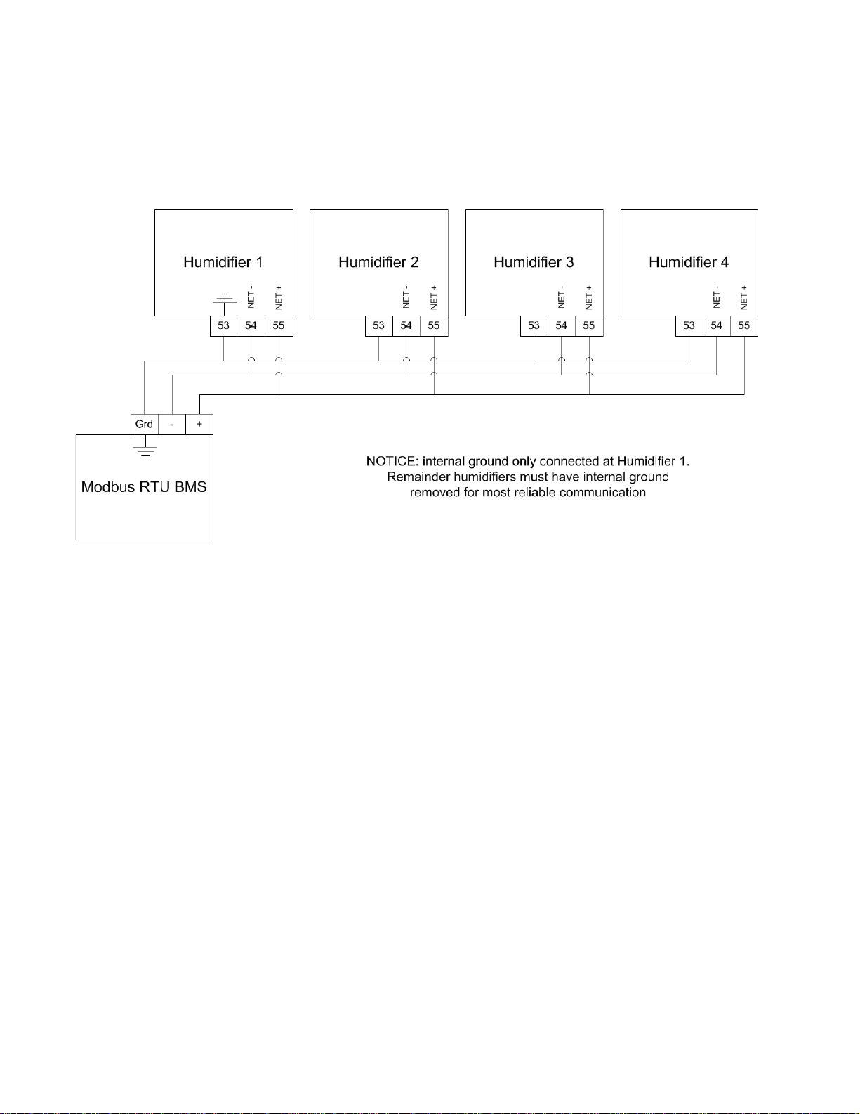
connected to a single chain/bus. The humidifiers should be the same type but do not need to
be the same capacity. For example it is not recommended to have an NHTC and a GSTC as part
of the same chain, but it is acceptable to have an NHTC-200 and an NHTC-30 as part of the
same chain. Connecting additional non-Nortec equipment into a Modbus chain is possible;
however it is important to ensure that all devices are operating with identical baud rate, parity,
and stop bits, and that each device has a unique Modbus address.
Figure 1: Example Daisy Chain Diagram for NH-EL, NHTC, GS, SE
Modbus Installation | 3
Page 7
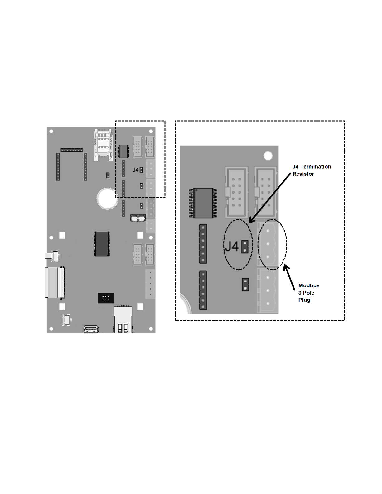
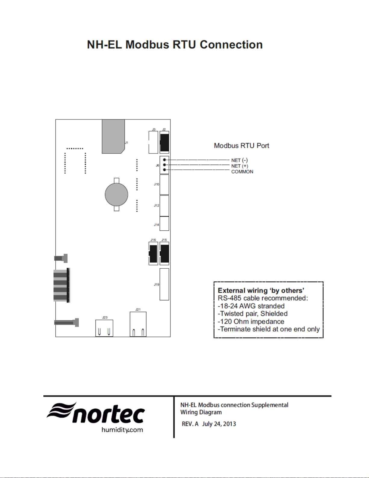
NH-EL Models
The NH-EL models use a 3 pole connector on the main processor card for Modbus connection.
This 3 pole connector is provided with all NH-EL and connections can be made directly to this
plug. Refer to Figure 2 and Figure 3 for connection location and wiring.
Please note: there is a 120 Ohm termination resistor available on board. When the jumper J4
is on, 120 Ohm is enabled. When the jumper J4 is off, 120 Ohm is disabled.
4 |Modbus Installation
Figure 2: NHEL Modbus 3 Pole Plug Location
Page 8

Note
NHTC, GSTC, SETC, and MHTC Models
The NHTC, GSTC, SETC, and MHTC models use a multifunction RJ45 plug on the mainboard to
provide Modbus communications. Connections can be made directly to this plug or,
alternatively, using one of accessories listed above.
Refer to figure 4 for information on the wiring connections for these units.
: This instruction manual covers the connections and points for the GSTC B+ and SETC B+
models only. Older models, manufactured pre-2009 do not include the RJ45 plug and require
an additional interface cable. Contact Nortec for information on connecting these units.
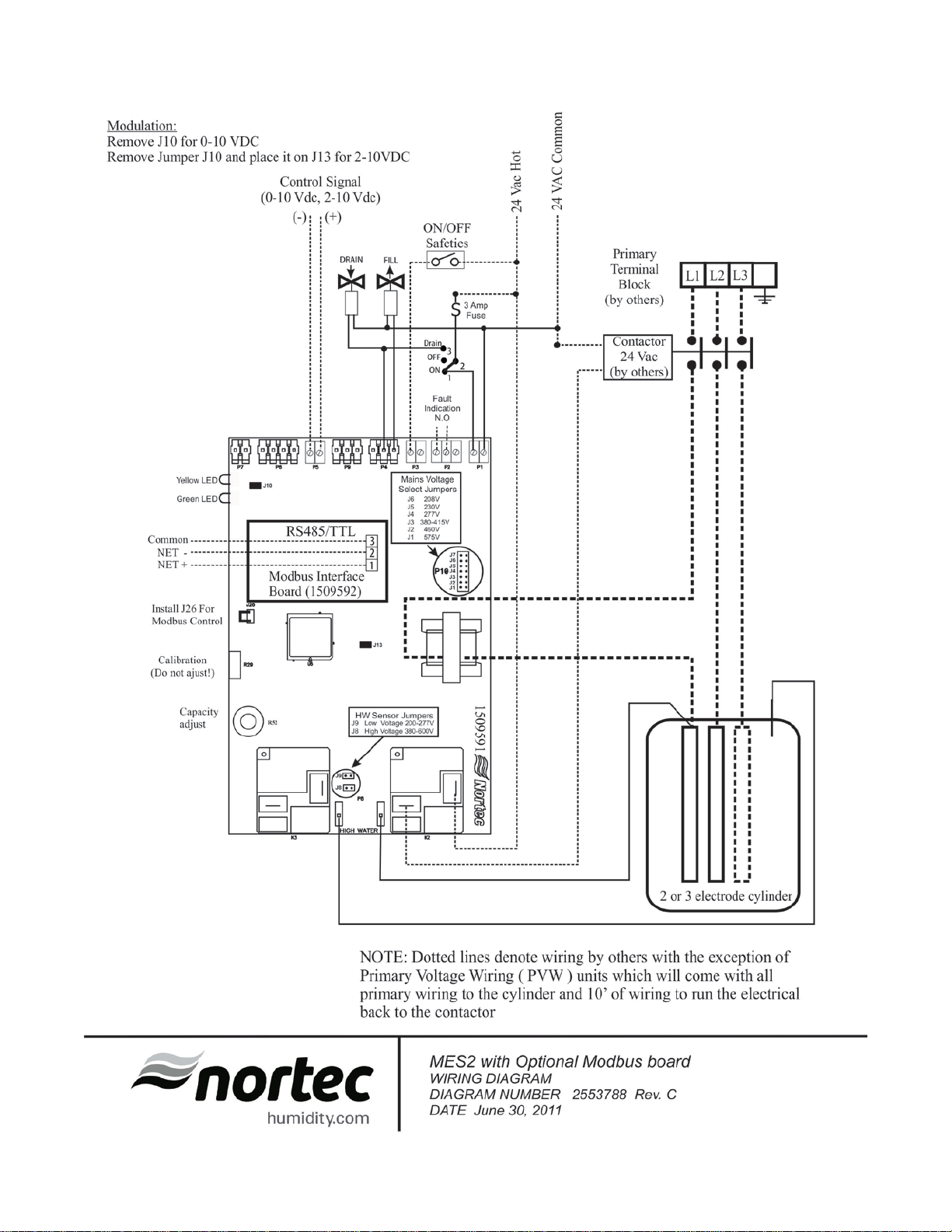
MES2 and RH2 Models
The MES2 and RH2 models require a Modbus support board to provide a connection point. This
board can be factory installed if indicated at time of order, or retrofit to existing units in the field.
Refer to Figure 5 for information on the wiring connections for these units.
NHRS Models
The NHRS models require a Modbus kit to translate information from the processor board into
Modbus RTU information. This kit can be factory installed if specified at time of order or retrofit
to existing units in the field. Refer to figure 6 for information on the wiring connections for these
units.
Modbus Installation | 5
Page 9
6 |Modbus Installation
Figure 3: NH-EL Modbus Wiring Diagram
Page 10

Figure 4: TC Modbus Wiring Diagram
Modbus Installation | 7
Page 11
8 |Modbus Installation
Figure 5: MES2 and RH2 Modbus Wiring Diagram
Page 12
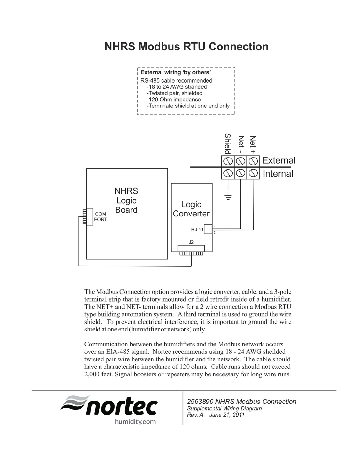
Figure 6: NHRS Modbus Wiring Diagram
Modbus Installation | 9
Page 13

Modbus Communication Set-up
1
2
3
4
5
Note: By default, Modbus is disabled. To enable Modbus, select
Modbus
under
Modbus
Parameters
. Select ON and confirm the selection by pressing the
Check Mark
button.
6
7
Addressing and Communications
Once the humidifier has been wired to the network, control variables must be mapped to allow
for control of the humidifier. The specific variables and communications requirements for each
humidifier are described in the following sections.
NH-EL Electrode Steam Humidifiers
After wiring connections have been completed, the humidifier needs to be setup to operate and
communicate either through the Modbus or BACnet interface.
The default Modbus address for an NH-EL is 10. If multiple units were included on an order, the
addresses of individual units may vary. To view or change the Modbus address:
Press the Menu icon on the lower left corner of the screen, to access the menu.
When prompted for a password, enter 0335 using the number pad. Press the Check Mark
icon to confirm.
Select the Configuration menu.
Select the Comms. menu.
Using the navigation buttons on the top right of the screen, scroll down to the Modbus
Parameters.
Select the Modbus Address setting. Using the Up and Down arrows, select a value between
1 and 247 inclusive as desired and press the Check Mark button to confirm the selection. It
is recommended to leave the parity and baud rate settings to their factory defaults (Even
and 9600 respectively) unless communication problems occur.
Press Back repeatedly until you return to the home screen.
This procedure is summarized below:
Main Menu > 0335 > Configuration > Comms. Menu > Modbus Parameters >
Addr: 10 (1 – 247 acceptable)
Parity: Even (None, Even, Odd)
Baud Rate: 9600 (9600, 19200, 38400, 115200)
10 |Modbus Installation
Page 14

Control Signal Setting
1
2
3
4
Note: Refer to the CONTROL SETTING section of the NH Series Installation and Operation
Manual for more information on the above settings.
5
Modbus Parameters
By default the humidifier is configured operate on a hardwired control signal supplied through
the unit terminal strip. This can be changed to allow the humidifier to function entirely through
its Modbus or BACnet interface.
To adjust this setting:
Press the Menu icon on the lower left corner of the screen, to access the menu.
When prompted for a password, enter 0335 using the number pad. Press the Check Mark
icon to confirm.
Select the Configuration menu.
Select the Control Settings menu. The following settings can be adjusted:
Source
Control Mode
Control Channels
Analog: Use hardwired control signal
Modbus: Write control signal through Modbus interface
Demand: Use a demand control signal
RH P: Use a sensor value and proportional
RH PI: Use a sensor value and proportional-integral control band
Single: Use a signal channel control signal
Dual: Use a dual channel control signal
Press Check Mark to confirm choice and then Back repeatedly to return to the home screen
when complete.
This procedure is summarized below:
Main Menu > 0335 > Configuration > Control Settings >
Source: Analog, Modbus,
Control Mode: Demand, RH P, or RH PI
Control Channels: Single or Dual
The NH-EL uses the following parameters for Modbus communication:
Signaling Type EIA-485
Transmission Mode RTU
Baud Rate 9600
Data Bits 8
Stop Bits 1
Parity Even
Address / Unit Number 10*
*Default, may vary for multi-unit orders.
It is important to note that the signaling type, transmission mode, data bits and stop bits cannot
be modified. Parity, baud rate and unit address can be modified as required.
Modbus Installation | 11
Page 15

Parameter
Name
Description
Modbus
Addr.
Type
Format
Range
Unit
R/W
Details
Write RH or
cylinder A
Requires Modbus or
primary control signal
Requires Modbus or
operation mode
Requires Modbus or
enabled
Requires Modbus or
operation mode
Limits output to
only)
Limits output to
only)
BMS timeout
BACnet
It is recommend to not
the factory default (300)
Remotely disable
for the unit
Writes the
for cylinder A
Use only when sending
primary space setpoint
Writes the
for cylinder A
The following points may be mapped for control:
Dinput_A1
Dinput_A2
Dinput_B1
Dinput_B2
Manual_
Capcity_A
Demand signal
value to control
channel 1 for
Write RH or
Demand signal
value to control
channel 2 for
cylinder A
Write RH or
Demand signal
value to control
channel 1 for
cylinder B
Write RH or
Demand signal
value to control
channel 2 for
cylinder B
Sets a manual
capacity limit
restriction for
cylinder A
40005
40006
40010
40011
40002
Holding
Register
Holding
Register
Holding
Register
Holding
Register
Holding
Register
Integer 0 - 100 % Write
Integer 0 - 100 % Write
Integer 0 - 100 % Write
Integer 0 - 100 % Write
Integer 0 - 100 % Write
BACnet to be enabled.
For most common
configurations, this is the
BACnet to be enabled.
Only applies to NH-EL150 and NH-EL-200 with
cylinders in independent
BACnet to be enabled.
Only applies to NH-EL150 and NH-EL-200 with
dual channel control
BACnet to be enabled.
Only applies to NH-EL150 and NH-EL-200 with
cylinders dual channel
control enabled and
cylinders in independent
percentage of total
cylinder capacity for
cylinder A (NH-EL-150
and NH-EL-200 models
Manual_
Capcity_B
BMS_
Timeout
Remote_
Disable
SP_Chan_A
1
SP_Chan_A
2
Sets a manual
capacity limit
restriction for
cylinder B (if
present)
for Modbus and
steam production
desired space
setpoint for
control channel 1
desired space
setpoint for
control channel 2
40007
40013
40001
40003
40004
Holding
Register
Holding
Register
Holding
Register
Holding
Register
Holding
Register
Integer 0 - 100 % Write
Integer 0 - 300 s Write
Integer 0 or 1 - Write
Integer 0 - 95 % Write
Integer 10 - 95 % Write
percentage of total
cylinder capacity for
cylinder B (NH-EL-150
and NH-EL-200 models
change the value from
0 = Idle/Humidify
1 = Disable
RH values to Dinput_A1.
For most common
configurations this is the
Use only when sending
RH value to Dinput_A2
with dual channel control
enabled
12 |Modbus Installation
Page 16

Use only with NH-EL-
mode
Use only with NH-EL-
mode
0 = Analog
4 = LonWorks
1 = Demand
3 = RH PI
Selects method
channels
Displays channel 1
capacity for cylinder A
Displays channel 2
capacity for cylinder A
Displays channel 1
200 models only)
Displays channel 2
200 models only)
Reads the status
A
Reads the status
B
SP_Chan_B
1
SP_Chan_B
2
Signal_
Source
Control_
Mode
Control_
Channel
Writes the
desired space
setpoint for
control channel 1
for cylinder B
Writes the
desired space
setpoint for
control channel 2
for cylinder B
Selects signal
source to control
unit
Selects method
to control unit
to control
40008
40009
40014
40015
40016
Holding
Register
Holding
Register
Holding
Register
Holding
Register
Holding
Register
Integer 0 - 95 % Write
Integer 10 - 95 % Write
Integer 0 - 4 - Write
Integer 1 - 3 - Write
Integer 0 - 1 - Write
150 and NH-EL-200
models when sending
RH value to Dinput_B1
and cylinders are in
independent operation
150 and NH-EL-200
models when sending
RH value to Dinput_B2
with dual channel
control enabled and
cylinders are in
independent operation
1 = Modbus
2 = BACnet/IP
3 = BACnet/MS
2 = RH P
0 = Single Channel
1 = Dual Channel
Input_A1
Input_A2
Input_B1
Input_B2
Blower_
Pack_A
Blower_
Pack_B
Displays channel
1 demand for
cylinder A
Displays channel
2 demand for
cylinder A
Displays channel
1 demand for
cylinder B
Displays channel
2 demand for
cylinder B
of the blower
pack for cylinder
of the blower
pack for cylinder
30004
30005
30014
30015
30008
30018
Input
Register
Input
Register
Input
Register
Input
Register
Input
Register
Input
Register
Integer 0 - 100 % Read
Integer 0 - 100 % Read
Integer 0 - 100 % Read
Integer 0 - 100 % Read
Integer 0 or 1 - Read
Integer 0 or 1 - Read
demand/sensed RH as
a percentage of cylinder
demand/sensed RH as
a percentage of cylinder
demand/sensed RH as
a percentage of cylinder
capacity for cylinder B
(NH-EL-150 and NH-EL-
demand/sensed RH as
a percentage of cylinder
capacity for cylinder B
(NH-EL-150 and NH-EL-
0 = Open
1 = Closed
0 = Open
1 = Closed
Fan_
Activate_A
Indicates if air
handle or
furnace is
activated for
cylinder A
30009
Input
Register
Integer 0 or 1 - Read
Modbus Installation | 13
0 = Not Activated
1 = Activated
Page 17

Indicates if air
cylinder B
Reads the status
unit
Reads the status
request on the unit
0 = No Service
1 = Service Required
0 = Humidifying
9 = Fault
0 = Humidifying
9 = Fault
Demand Mode:
PID calculation
Demand Mode:
PID calculation
Reads the status
for cylinder A
Reads the status
for cylinder B
Displays the total time
running since last reset
Displays the total time
running since last reset
Reads the
cylinder A
An equated run time
System_Demand_A
Reads the
cylinder B
An equated run time
System_Demand_A
Fan_
Activate_B
Do_Fault_
A
Do_
Service_A
Humidifier
_Status_A
Humidifier
_Status_B
handle or furnace
is activated for
of a fault on the
of a service
Reads the status
of the unit for
cylinder A
Reads the status
of the unit for
cylinder A
30019
30025
30024
30003
30026
Input
Register
Input
Register
Input
Register
Input
Register
Input
Register
Integer 0 or 1 - Read
Integer 0 or 1 - Read
Integer 0 or 1 - Read
Integer 0 - 9 - Read
Integer 0 - 9 - Read
0 = Not Activated
1 = Activated
0 = No Fault
1 = Fault
Required
1 = Idle
2 = Idle Drain
3 = Keepwarm
4 = Filling
5 = Draining
6 = Disabled
7 = Safety Loop
8 = Warning
1 = Idle
2 = Idle Drain
3 = Keepwarm
4 = Filling
5 = Draining
6 = Disabled
7 = Safety Loop
8 = Warning
System_
Demand_A
System_
Demand_
B
Safety_
Loop_A
Safety_
Loop_B
Run_Time
_A
Run_Time
_B
Weighted_
Hours_A
Weighted_
Hours_B
Reads the demand
for cylinder A
Reads the demand
for cylinder A
of the safety loop
of the safety loop
Reads operating
time for cylinder A
Reads operating
time for cylinder B
weighted time for
weighted time for
30006
30016
30007
30017
30010
30020
30011
30021
Input
Register
Input
Register
Input
Register
Input
Register
Input
Register
Input
Register
Input
Register
Input
Register
Integer 0 – 100 % Read
Integer 0 – 100 % Read
Integer 0 or 1 - Read
Integer 0 or 1 - Read
Integer 0 - 5000 Hrs Read
Integer 0 - 5000 Hrs Read
Integer 0 - 5000 Hrs Read
Integer 0 - 5000 Hrs Read
Summation of Input_A1
and Input_A2
RH Mode:
Summation of Input_B1
and Input_B2
RH Mode:
0 = Open
1 = Closed
0 = Open
1 = Closed
cylinder A has been
cylinder B has been
based on Run_Time_A x
based on Run_Time_A x
14 |Modbus Installation
Page 18

Modbus Address
1
2
3
4
5
Note: Do NOT modify other settings in the Factory settings manual. Adjusting other settings
can cause serious damage to the humidifier.
6
7
NHTC Electrode Steam Humidifiers
After wiring connections have been completed, the humidifier needs to be setup to operate and
communicate through the Modbus interface.
The default Modbus address for an NHTC is 1. If multiple units were included on an order, the
addresses of individual units may vary. To view or change the unit number:
Press the Menu key to access the menu.
When prompted for a password, enter 0459 using the arrow keys. Press Set to confirm.
Select the Factory Settings menu and press the Set key.
Select the Core Parameters menu and press the Set key.
Select the Modbus Parameters menu and press the Set key.
Select the Address setting and press Set to modify. Enter a value between 1 and 127
inclusive as desired and press Set to confirm the solution. It is recommended to leave the
parity and timeout settings to their factory defaults (Even and 300 respectively) unless
communication problems occur.
Press Esc repeatedly until you return to the home screen.
This procedure is summarized below:
Menu > 0459 > Factory Settings > Core Parameters > Modbus Parameters >
Parity: Even
Addr: 1 (Default, 1 – 127 acceptable)
Timeout: 300 seconds (Default, 5 – 600 acceptable)
Modbus Installation | 15
Page 19

Control Signal Setting
1
2
3
Note: Refer to the CONTROL SETTING section of the NH Series Installation and Operation
Manual for more information on the above settings.
4
By default the humidifier operation is configured on a hardwired control signal supplied through
the unit terminal strip. This can be changed to allow the humidifier to function entirely through
its Modbus interface.
To adjust this setting:
Press the Menu key to access the menu.
When prompted for a password, enter 0335 using the arrow keys. Confirm the password
with set.
Select the Control Settings menu and press the Set key. The following settings can be
adjusted:
Source
REG Mode
MOD Mode
CNT Type Setting not relevant when writing control signal through Modbus.
Analog: Use hardwired control signal
Digital: Write control signal through Modbus interface
Demand: Use a demand control signal
RHp: Use a sensor value and proportional
RHpi: Use a sensor value and proportional-integral control band
Single CH: Use a signal channel control signal
Dual CH: Use a dual channel control signal
Press Esc repeatedly to return to the home screen when complete.
This procedure is summarized below:
Menu > 0335 > Control Settings >
Source: Analog or Digital
Reg Mode: Demand, RHp, or RHpi
Mod Mode: Single CH or Dual CH
CNT Type: As required
16 |Modbus Installation
Page 20

Modbus Parameters
Address / Unit Number
1*
The NHTC uses the following parameters for communication:
Signaling Type EIA-485
Transmission Mode RTU
Baud Rate 9600
Data Bits 8
Stop Bits 1
Parity Even
*Default, may vary for multi-unit orders.
It is important to note that the signaling type, transmission mode, baud rate, data bits and stop
bits cannot be modified. Parity and unit address can be modified as required.
Modbus Installation | 17
Page 21

Variable Name
Description
Addr.
Type
Format
Range
Uni
t
R/W
Details
Sets a
cylinder 1.
Sets a
present).
Write RH or
cylinder 1
Write RH or
cylinder 2
Requires network controls
mode
Write RH or
cylinder 1
Requires network controls
mode
Writes the
cylinder 1
Writes the
cylinder 2
Use only with NHTC-150
mode
Writes the
cylinder 1
The following points may be mapped for control:
CapLimitCyl1
CapLimitCyl2
RHDemCyl1
RHDemCyl2
RHDem2Cyl1
manual
capacity
restriction for
manual
capacity
restriction for
cylinder 2 (if
Demand
signal value
to control
channel 1 for
Demand
signal value
to control
channel 1 for
Demand
signal value
to control
channel 2 for
40026
41026
40264
41264
40265
Holding
Register
Holding
Register
Holding
Register
Holding
Register
Holding
Register
Integer
Integer
Integer 0 - 100 % Write
Integer 0 - 100 % Write
Integer 0 - 100 % Write
50-
100
50-
100
% Write
% Write
Limits output to
percentage of total
cylinder capacity
Limits output to
percentage of total
cylinder capacity for
cylinder 2 (NHTC-150 and
NHTC-200 models only)
Requires network controls
(NetSensor = 1), for most
common configurations
this is the primary control
signal
(NetSensor = 1), only
applies to NHTC-150 and
NHTC-200 with cylinders
in independent operation
Requires network controls
(NetSensor = 1), only
applies to NHTC-150 and
NHTC-200 with dual
channel control enabled
RHDem2Cyl2
Set1Cyl1
Set1Cyl2
Set2Cyl1
Write RH or
Demand
signal value
to control
channel 2 for
cylinder 2
desired space
setpoint for
control
channel 1 for
desired space
setpoint for
control
channel 1 for
desired space
setpoint for
control
channel 2 for
41265
40024
41024
40010
Holding
Register
Holding
Register
Holding
Register
Holding
Register
Integer 0 - 100 % Write
Integer 30-95 % Write
Integer 30-95 % Write
Integer 30-95 % Write
(NetSensor = 1), only
applies to NHTC-150 and
NHTC-200 with cylinders
dual channel control
enabled and cylinders in
independent operation
Use only when sending RH
value to RHDem1, for
most common
configurations this is the
primary space setpoint
and NHTC-200 models
when sending RH value to
RHDem1 and cylinders are
in independent operation
Use only when sending RH
value to RHDem2 with
dual channel control
enabled
18 |Modbus Installation
Page 22

Use only with NHTC-150
mode
Remotely
cylinder 1
Used only for NHTC-150
255 = Disabled
Switches
control signal
Displays
cylinder 1
Displays channel 1
cylinder 1
Displays channel 1
200 models only)
Displays
cylinder 1
Displays channel 2
cylinder 1
Displays channel 2
200 models only)
Reads fault
status
Input
Register
0 or
255
0 = No Fault
255 = Fault Warning
Reads service
status
0 = Idle / Standby
Humidifying
Reads operating time for
hours = (Value x 5)/60
Writes the
desired space
Set2Cyl2
DisableCyl1
DisableCyl2
NetSensor
setpoint for
control
channel 2 for
cylinder 2
disable steam
production for
Remotely
disable steam
production for
cylinder 2
between hard
wired or
network
41010
40262
41262
40226
Holding
Register
Holding
Register
Holding
Register
Holding
Register
Integer 30-95 % Write
Integer
Integer
Integer 0 or 1 - Write
0 or
255
0 or
255
- Write
- Write
and NHTC-200 models
when sending RH value to
RHDem2 with dual
channel control enabled
and cylinders are in
independent operation
0 = Normal operation
255 = Disabled
and NHTC-200 models.
Both cylinder 1 and 2
must be disabled to
completely disable
humidifier.
0 = Normal operation
1= Network sensor or
demand
0 = Wired sensor or wired
demand
Ch1DemCyl1
Ch1DemCyl2
Ch2DemCyl1
Ch2DemCyl2
Fault Warning
Service Warning
channel 1
demand for
Displays
channel 1
demand for
cylinder 2
channel 2
demand for
Displays
channel 2
demand for
cylinder 2
warning
30348
31348
30349
31349
30301
30300
Input
Register
Input
Register
Input
Register
Input
Register
Input
Register
Integer
Integer
Integer
Integer
Integer
Integer
0 -
100
0 -
100
0 -
100
0 -
100
0 or
255
% Read
% Read
% Read
% Read
- Read
- Read
demand as a percentage
of cylinder capacity for
demand / output as a
percentage of cylinder
capacity for cylinder 2
(NHTC-150 and NHTC-
demand as a percentage
of cylinder capacity for
demand / output as a
percentage of cylinder
capacity for cylinder 2
(NHTC-150 and NHTC-
0 = No Service Warning
255 = Service Warning
Unit Status
Cyl1OpTime
Reads unit
status
Reads
operating
time for
cylinder 1
30312
30213
Input
Register
Input
Register
Integer
Integer
0 or
255
0 -
65535 5 min
- Read
255 = Active /
cylinder 1. Each number
Read
Modbus Installation | 19
is equivalent to 5 minutes
of operation. Time in
Page 23

Reads operating time
5)/60
11 = Security loop open
run for 72hrs
Unit will not run until
fault
Displays the
cylinders)
Cyl2OpTime
UnitStatus
Reads
operating
time for
cylinder 2
Displays
status
warnings
31213
31385
Input
Register
Input
Register
0 -
Integer
Integer 0-99 - Read
6553
5
5
min
Read
for cylinder 2 (NHTC150 and NHTC-200
only). Each number is
equivalent to 5 minutes
of operation.
Time in hours = (Value x
19 = Cylinder spent
warning
If status 19, unit will
have yellow service light
on and will continue to
CylSpent
SysTotalDem
Displays
cylinder end
of life fault
total demand
on system
(sum both
30378
30251
Input
Register
Input
Register
Integer 0-99 - Read
Integer
0 -
100
% Read
cylinder is replaced
19 = Cylinder spend
Sum of Steam Output
Cyl-1 and Cyl-2 in
percentage
20 |Modbus Installation
Page 24

Modbus Address
1
2
3
4
5
6
Control Signal Setting
GSTC Gas Fired Steam Humidifiers
After wiring connections have been completed, the humidifier needs to be setup to operate and
communicate through the Modbus interface.
The default Modbus address for a GSTC is 1. If multiple units were included on an order, the
addresses of individual units may vary.
To view or change the unit number:
Press the Menu key to access the menu.
When prompted for a password, enter 0335 using the arrow keys. Press Set to confirm.
Select the Control Settings menu and press the Set key.
Select the Modbus Parameters menu and press the Set key.
Select the Address setting and press Set to modify. Enter a value between 1 and 127
inclusive as desired and press Set to confirm the solution. It is recommended to leave the
parity and timeout settings to their factory defaults (None1 and 300 respectively) unless
communication problems occur.
Press Esc repeatedly until you return to the home screen.
This procedure is summarized below:
Menu > 0335 > Control Settings > Modbus Parameters >
Parity: None1
Addr: 1 (Default, 1 – 127 acceptable)
Timeout: 300 seconds (Default, 5 – 600 acceptable)
By default the humidifier is configured operate on a hardwired control signal supplied through
the unit terminal strip. This can be changed to allow the humidifier to function entirely through
its Modbus interface.
Modbus Installation | 21
Page 25

1
2
3
Note: Refer to the
GSTC Total Controller Flow Chart
section of the GS Series Installation and
Operation Manual for more information on the above settings.
4
Modbus Parameters
Signaling Type
EIA-485
Transmission Mode
RTU
Baud Rate
9600
Data Bits
8
Stop Bits
1
Parity
None
Address / Unit Number
1*
To adjust this setting:
Press the Menu key to access the menu.
When prompted for a password, enter 0335 using the arrow keys. Confirm the password
with set.
Select the Control Settings menu and press the Set key. The following settings can be
adjusted:
Source:
REG Mode:
MOD Mode:
CNT Type: Setting not relevant when writing control signal through modbus.
Analog: Use hardwired control signal
Digital: Write control signal through modbus interface
Demand: Use a demand control signal
RHp: Use a sensor value and proportional
RHpi: Use a sensor value and proportional-integral control band
Single CH: Use a signal channel control signal
Dual CH: Use a dual channel control signal
Press Esc repeatedly to return to the home screen when complete.
This procedure is summarized below:
Menu > 0335 > Control Settings >
Source: Analog or Digital
Reg Mode: Demand, RHp, or RHpi
Mod Mode: Single CH or Dual CH
CNT Type: As required
The GSTC uses the following parameters for communication:
*Default, may vary for multi-unit orders.
It is important to note that the signaling type, transmission mode, baud rate, data bits and stop
bits cannot be modified. Parity and unit address can be modified as required.
22 |Modbus Installation
Page 26

Variable
Name
Description
Addr
Type
Format
Range
Unit
R/W
Additional Details
Write RH or
channel 1
Write RH or
channel 2
Writes the
control channel 1
Writes the
control channel 2
Remotely
humidifier
0 = Demand Signal
Integral Control)
0 = Hard wired
value
Read RH or
1
Read RH or
2
Read space
control channel 1
Read space
control channel 2
Confirms remote
disable status
Input
Register
0 = Run
255 = Disable
The following points may be mapped for control:
RHDem1
RhDem2
Set1
Set2
Disable
InputType
Demand signal
value to control
Demand signal
value to control
desired space
setpoint for
desired space
setpoint for
disables the
Selects the
control type that
the humidifier
operates on
40264
40265
40024
40025
40262
40007
Holding
Register
Holding
Register
Holding
Register
Holding
Register
Holding
Register
Holding
Register
Analog 0-100 % Write
Analog 0-100 % Write
Analog 30-95 % Write
Analog 30-95 % Write
Analog 0, 255 - Write
Analog
0,1,2,3
,
- Write
Requires network
controls
(NetSensor = 1)
Requires network
controls
(NetSensor = 1)
Use only when
sending RH value
to RHDem1
Use only when
sending RH value
to RHDem2
0 = Run
255 = Disable
1 = On/Off Signal
2 = RH Sensor
Value (Use
Proportional
Control)
3 = RH Sensor
Value (Use
Proportional-
NetSensor
RHDem1
RHDem2
Set1
Set2
Disable
Switches
between hard
wired or network
control signal
Demand signal
value from
control Channel
Demand signal
value from
control Channel
setpoint for
setpoint for
40226
30348
30349
40024
40025
30989
Holding
Register
Input
Register
Input
Register
Input
Register
Input
Register
Binary 0,1 - Write
Analog 0-100 % Read
Analog 0-100 % Read
Analog 30-95 % Read
Analog 30-95 % Read
Analog 0, 255 - Read
control signal
1 = Use Modbus to
write control signal
Displays signal
value as a
percentage
Displays signal
value as a
percentage
Only available for
InputType 2 or 3
Only available for
InputType 2 or 3
Modbus Installation | 23
Page 27

0 = Demand Signal
Integral Control)
0 = Hard wired
value
Read fault
status
Input
Register
0 = No Fault
1 = Fault Detected
0 = No Service
Required
Read
status
0 = Idle / Standby
Humidifying
0 = Communication
Communication
Read
hours of unit
Read
at humidifier)
Read 3 day
at humidifier)
SysDemand
Read system
demand
Displays output as
capacity
Read hours
service
Displays hours
next service.
Displays the status
1 = Closed
InputType
Confirms the
control type
that the
humidifier
operates on
40007
Input
Register
Analog 0,1,2,3 - Read
1 = On/Off Signal
2 = RH Sensor
Value (Use
Proportional
Control)
3 = RH Sensor
Value (Use
Proportional-
Confirms the
NetSensor
Fault
Service
Status
Connection
HourOpt
KeepWarm
system control
type
Read service
warning status
humidification
Read
connection
status
operational
keepwarm
option status
(enable/disable
40226
30301
30300
30302
40267
30350
30356
Input
Register
Input
Register
Input
Register
Input
Register
Input
Register
Input
Register
Binary 0,1 - Read
Binary 0,1 - Read
Binary 0,1 - Read
Binary 0,1 - Read
Binary 0,1 - Read
Analog
Analog 0,1 - Read
0 -
Infinity
hrs Read
control signal
1 = Use Modbus to
write control signal
Warning
1 = Service
1 = Active /
Error
1 = Normal
Displays hours of
operation.
Bit0 - KEEPWARM
0 = Disabled
1 = Enabled
3DayDrain
ServHours
SecurityLoop
24 |Modbus Installation
drain option
status
(enable/disable
output /
before next
Displays status
of security loop.
30356
30347
30352
30364
Input
Register
Input
Register
Input
Register
Input
Register
Analog 0,1 - Read
Analog 0-100 % Read
Analog 500-0 hrs Read
Analog 0,1 - Read
Bit1 - 3 DAY DRAIN
0 = Disabled
1 = Enabled
percentage of
remaining until
of the security loop
on terminals 1 and
2. Loop must be
"closed" for
humidifier to
operate.
0 = Open
Page 28

Modbus Address
1
2
3
4
5
6
SETC Steam Exchange Humidifiers
After wiring connections have been completed, the humidifier needs to be setup to operate and
communicate through the Modbus interface.
The default Modbus address for a SETC is 1. If multiple units were included on an order, the
addresses of individual units may vary.
To view or change the unit number:
Press the Menu key to access the menu.
When prompted for a password, enter 0335 using the arrow keys. Press Set to confirm.
Select the Control Settings menu and press the Set key.
Select the Modbus Parameters menu and press the Set key.
Select the Address setting and press Set to modify. Enter a value between 1 and 127
inclusive as desired and press Set to confirm the solution. It is recommended to leave the
parity and timeout settings to their factory defaults (None1 and 300 respectively) unless
communication problems occur.
Press Esc repeatedly until you return to the home screen.
This procedure is summarized below:
Menu > 0335 > Control Settings > Modbus Parameters >
Parity: None1
Addr: 1 (Default, 1 – 127 acceptable)
Timeout: 300 seconds (Default, 5 – 600 acceptable)
Modbus Installation | 25
Page 29

Control Signal Setting
1
2
3
Note: Refer to the
SETC Humidifier Configuration
section of the SE Series Installation and
Operation Manual for more information on the above settings.
1
Modbus Parameters
Signaling Type
EIA-485
Transmission Mode
RTU
Baud Rate
9600
Data Bits
8
Stop Bits
1
Parity
None
Address / Unit Number
1*
By default the humidifier is configured operate on a hardwired control signal supplied through
the unit terminal strip. This can be changed to allow the humidifier to function entirely through
its Modbus interface.
To adjust this setting:
Press the Menu key to access the menu.
When prompted for a password, enter 0335 using the arrow keys. Confirm the password
with set.
Select the Control Settings menu and press the Set key. The following settings can be
adjusted:
Source
REG Mode
MOD Mode
CNT Type Setting not relevant when writing control signal through Modbus.
Analog: Use hardwired control signal
Digital: Write control signal through Modbus interface
Demand: Use a demand control signal
RHp: Use a sensor value and proportional
RHpi: Use a sensor value and proportional-integral control band
Single CH: Use a signal channel control signal
Dual CH: Use a dual channel control signal
Press Esc repeatedly to return to the home screen when complete.
This procedure is summarized below:
Menu > 0335 > Control Settings >
Source: Analog or Digital
Reg Mode: Demand, RHp, or RHpi
Mod Mode: Single CH or Dual CH
CNT Type: As required
The SETC uses the following parameters for communication:
*Default, may vary for multi-unit orders.
It is important to note that the signaling type, transmission mode, baud rate, data bits and stop
bits cannot be modified. Parity and unit address can be modified as required.
26 |Modbus Installation
Page 30

Variable
Name
Description
Addr
Type
Format
Range
Unit
R/W
Additional Details
Write RH or
channel 1
Write RH or
channel 2
Writes the desired
control channel 1
Writes the desired
control channel 2
Remotely disables
the humidifier
Holding
Register
0 = Run
255 = Disable
0 = Demand Signal
Control)
Switches between
signal
0 = Hard wired control
control signal value
Read RH or
Channel 1
Read RH or
Channel 2
Read space
channel 1
Read space
channel 2
Confirms remote
disable status
Input
Register
0 = Run
255 = Disable
0 = Demand Signal
Control)
The following points may be mapped for control:
RHDem1
RhDem2
Set1
Set2
Disable
InputType
NetSensor
Demand signal
value to control
Demand signal
value to control
space setpoint for
space setpoint for
Selects the control
type that the
humidifier
operates on
hard wired or
network control
40264
40265
40024
40025
40262
40007
40226
Holding
Register
Holding
Register
Holding
Register
Holding
Register
Holding
Register
Holding
Register
Analog 0-100 % Write
Analog 0-100 % Write
Analog 30-95 % Write
Analog 30-95 % Write
Analog 0, 255 - Write
Analog 0,1,2,3 - Write
Binary 0,1 - Write
Requires network controls
(NetSensor = 1)
Requires network controls
(NetSensor = 1)
Use only when sending RH
value to RHDem1
Use only when sending RH
value to RHDem2
1 = On/Off Signal
2 = RH Sensor Value (Use
Proportional Control)
3 = RH Sensor Value (Use
Proportional-Integral
signal
1 = Use Modbus to write
RHDem1
RHDem2
Set1
Set2
Disable
InputType
Demand signal
value from control
Demand signal
value from control
setpoint for control
setpoint for control
Confirms the
control type that
the humidifier
operates on
30348
30349
40024
40025
30989
40007
Input
Register
Input
Register
Input
Register
Input
Register
Input
Register
Analog 0-100 % Read
Analog 0-100 % Read
Analog 30-95 % Read
Analog 30-95 % Read
Analog 0, 255 - Read
Analog 0,1,2,3 - Read
Displays signal value as a
percentage
Displays signal value as a
percentage
Only available for InputType
2 or 3
Only available for InputType
2 or 3
1 = On/Off Signal
2 = RH Sensor Value (Use
Proportional Control)
3 = RH Sensor Value (Use
Proportional-Integral
Modbus Installation | 27
Page 31

0 = Hard wired control
control signal value
Input
Register
0 = No Fault
1 = Fault Detected
Read service
warning status
Input
Register
0 = No Service Warning
1 = Service Required
Read
status
0 = Communication Error
Communication
Read operational
hours of unit
Input
Register
0 -
Infinity
Displays hours of
operation.
Read keepwarm
humidifier)
Read 3 day drain
humidifier)
SysDemand
Read system
output / demand
Input
Register
Displays output as
percentage of capacity
Read hours before
next service
Input
Register
Displays hours remaining
until next service.
Displays the status of the
1 = Closed
Confirms the
NetSensor
Fault Read fault status 30301
Service
Status
Connection
HourOpt
KeepWarm
3DayDrain
system control
type
humidification
Read connection
status
option status
(enable/disable at
option status
(enable/disable at
40226
30300
30302
40267
30350
30356
30356
Input
Register
Input
Register
Input
Register
Input
Register
Input
Register
Binary 0,1 - Read
Binary 0,1 - Read
Binary 0,1 - Read
Binary 0,1 - Read
Binary 0,1 - Read
Analog
Analog 0,1 - Read
Analog 0,1 - Read
hrs Read
signal
1 = Use Modbus to write
0 = Idle / Standby
1 = Active / Humidifying
1 = Normal
Bit0 - KEEPWARM
0 = Disabled
1 = Enabled
Bit1 - 3 DAY DRAIN
0 = Disabled
1 = Enabled
ServHours
SecurityLoop
Displays status of
security loop.
30347
30352
30364
Input
Register
Analog 0-100 % Read
Analog 500-0 hrs Read
Analog 0,1 - Read
security loop on terminals
1 and 2. Loop must be
"closed" for humidifier to
operate.
0 = Open
28 |Modbus Installation
Page 32

Modbus Address
1
2
3
4
5
6
7
MHTC Evaporative Media Humidifiers
After wiring connections have been completed, the humidifier needs to be setup to operate and
communicate through the Modbus interface.
The default Modbus address for a MHTC is 1. If multiple units were included on an order, the
addresses of individual units may vary.
To view or change the unit number:
Press the Menu key to access the menu.
Select the User option and press Set.
When prompted for a password, enter 8808 using the arrow keys. Press Set to confirm.
Select the Settings menu and press the Set key.
Select the Modbus menu and press the Set key.
Select the Address setting and press Set to modify. Enter a value between 1 and 127
inclusive as desired and press Set to confirm the solution. It is recommended to leave the
parity and timeout settings to their factory defaults (None1 and 300 respectively) unless
communication problems occur.
Press Esc repeatedly until you return to the home screen.
This procedure is summarized below:
Menu > User > 8808 > Modbus >
Parity: None1
Addr: 1 (Default, 1 – 127 acceptable)
Timeout: 300 seconds (Default, 5 – 600 acceptable)
Modbus Installation | 29
Page 33

Control Signal Setting
1
2
3
4
Note: Refer to the
MHTC Humidifier Configuration
section of the MH Series Installation and
Operation Manual for more information on the above settings.
1
By default the humidifier is configured operate on a hardwired control signal supplied through
the unit terminal strip. This can be changed to allow the humidifier to function entirely through
its Modbus interface.
To adjust this setting:
Press the Menu key to access the menu.
Select the User options and press Set.
When prompted for a password, enter 8808 using the arrow keys. Confirm the password
with set.
Select the Controls menu and press the Set key. The following settings can be adjusted:
Signal Source
Hum. Control
Control Sign Setting not relevant when writing control signal through Modbus.
Analog: Use hardwired control signal
Modbus: Write control signal through Modbus interface
External: Use a demand control signal
Int(p): Use a sensor value and proportional
int(pi): Use a sensor value and proportional-integral control band
Press Esc repeatedly to return to the home screen when complete.
This procedure is summarized below:
Menu > User > 8808 > Controls >
Signal Source: Analog or Modbus
Hum. Control: External, Int(p), or Int(pi)
Control Sign: As required
30 |Modbus Installation
Page 34

Modbus Parameters
Signaling Type
EIA-485
Transmission Mode
RTU
Baud Rate
9600 (cannot be changed)
Data Bits
8
Stop Bits
1
Parity
None
Address / Unit Number
1*
Variable
Name
Description
Addr
Type
Format
Range
Unit
R/W
Details
Writes a control
error.
Reads/Writes
setpoint
Used when
0 = Allow normal
humidifier
0 = Demand Signal
method)
The MHTC uses the following parameters for communication:
*Default, may vary for multi-unit orders.
It is important to note that the signaling type, transmission mode, baud rate, data bits and stop
bits cannot be modified. Parity and unit address can be modified as required.
The following points may be mapped for control:
CapLimit
RHDem1
Set1
Disable
Manual
Capacity Limit
Reads/writes
a control
signal to the
humidifier
the desired
space
Remotely
disables
humidifier
40008
40053
40005
40052
Holding
Register
Holding
Register
Holding
Register
Holding
Register
Integer
Integer
Integer
Integer 0 or 1 - Write
30 100
0 -
100
10 -
90
% Write Limits unit output.
% Write
% Write
signal to the
humidifier. This input
only works if
humidifier is set to
network control
NetSensor set to 1)
in the control
settings. If the
system is set to
network control no
signal is detected,
the unit will display
the modbus timeout
Hum_Control = 2 or
3 only
humidifier operation
1 = Remotely
disables the
Selects the
Hum_Contr
ol
control type
that the
humidifier
operates on
40003
Holding
Register
Integer 0 - 3 - Write
1 = On/Off Signal
2 = RH Sensor Value
(Use Proportional
control method)
3 = RH Sensor Value
(Use ProportionalIntegral control
Modbus Installation | 31
Page 35

Switches
control signal
Indicates
stage 1
Indicates
stage 2
Indicates
stage 3
Indicates
status
Indicates
requirement
0 = No service
1 = Service required
Indicates fault
status
Input
Register
0 = No error
1 = Error(s) detected
Indicates
cycle status
Indicates
status
Displays
hours
Displays UV
hours
Displays unit
hours
Indicates
and 2)
Humidifier will only
1 = On
0 = Tank below full
1 = Tank full
Indicates
stages
NetSensor
Stage1Dem
Stage2Dem
Stage3Dem
Warning
Service
Fault
between hard
wired or
network
output from
humidifier
output from
humidifier
output from
humidifier
warning
maintenance
40002
30025
30026
30027
30015
30016
30017
Holding
Register
Input
Register
Input
Register
Input
Register
Input
Register
Input
Register
Integer 0 or 1 - Write
Integer 0 or 1 - Read
Integer 0 or 1 - Read
Integer 0 or 1 - Read
Integer 0 or 1 - Read
Integer 0 or 1 - Read
Integer 0 or 1 - Read
0 = Wired Analog
Sensor/Demand
1 = Modbus/Remote
Sensor/Demand
0 = Inactive
1 = Active
0 = Inactive
1 = Active
0 = Inactive
1 = Active
0 = No warning
1 = Warning
required
Cleaning
TankDrain
PumpRunHr
UVRunHr
ServTime
Security
TankLevel
automatic
stage cleaning
automatic
tank drain
pump
operational
lamp
operational
operational
security loop
status
(humidifier
terminals 1
Max Level
Sensor
30018
30019
30100
30101
30102
30200
30202
Input
Register
Input
Register
Input
Register
Input
Register
Input
Register
Input
Register
Input
Register
Integer 0 or 1 - Read
Integer 0 or 1 - Read
Integer
Integer
Integer
Integer 0 or 1 - Read
Integer 0 or 1 - Read
0 -
65535
0 -
65535
0 -
65535
10
min
10
min
10
min
Read
Read
Read
0 = Inactive
1 = Active
0 = Inactive
1 = Active
1Bit = 10min (max.
10’922h)
1Bit = 10min (max.
10’922h)
1Bit = 10min (max.
10’922h)
operate when
security loop is
closed.
0 = Off
level
System
Ready
32 |Modbus Installation
when the
humidifier is
ready to
commence
30013
Input
Register
Integer 0 or 1 - Read
0 = System busy
(cleaning or draining)
1 = System ready to
Humidify
Page 36

1
2
3
Jumper Position
Function
J26 Removed
Terminal strip control
J26 Installed
Modbus control
Signaling Type
EIA-485
Transmission Mode
RTU
Baud Rate
9600 (can be changed to 4800 bps or 19200 bps)
Data Bits
8
Stop Bits
1
Parity
Even
Address / Unit Number
1*
MES2 and RH2 Models
The default Modbus address for a humidifier is 1.
To view or change the unit number:
Establish Modbus communications and map desired points as indicated in the following
table.
Read the current Modbus address from variable 40201.
Change this address by writing the desired value to 40201. Values of 1 – 255 are
acceptable.
By default the MES2 and RH2 are configured operate on a control signal supplied through the
unit terminal strip. This can be changed to allow the humidifier to function entirely through its
Modbus interface. This is configured by removed Jumper 26 from the humidifier circuit board.
MES2 and RH2 Electrode Steam OEM Humidifiers
The MES2 and RH2 both use the following parameters for communication:
*Default, may vary for multi-unit orders.
Modbus Installation | 33
Page 37

Variable
Name
Description
Addr
Type
Format
Range
Unit
R/W
Details
0 = Disable operation of
Notes:
-
255 is written.
Imposes a
capacity.
0 = Normal operation
Notes:
normal operation.
Writes a
humidifier.
Default = 1. Values of 1 -
power cycled.
The following points may be mapped for control:
Configures
how
HumEnable
humidifier
responds to
modbus
controls
40003
Holding
Register
Integer 0,255 - Write
humidifier (Default Value)
255 = Allow operation of
humidifier within limits
specified by CapLimit
If a valid Modbus
message is not received
within the timeout
windows, this parameter
reverts to 0.
- This value cannot be set
when the FORCE DRAIN is
activated as. FORCE
DRAIN temporarily sets
this to value 0.
- Jumper J26 must be
installed to write any
parameter over the
Modbus. J26 sets it into
the control mode.
- Opening of the
hardwired security loop
(terminals 1 and 2) will
override operation even if
CapLimit
ForceDrain
ModAddress
maximum
output limit
as
percentage
of unit
Manually
initiates a
drain
period.
new
Modbus
address for
the
40004
40005
40201
Holding
Register
Holding
Register
Holding
Register
Integer
Integer 0, 255 - Write
Integer 1-255 - Write
25 100
% Write
Values outside of 25 100% return an error.
Default on startup = 25.
(Default)
255 = Initiate a 20
minute timer during which
the drain is active.
- During a force drain,
humidification ceases.
- Writing 0 during 20
minute period will cancel
the drain.
- After 20 minutes this
value will revert to 0 and
the humidifier will resume
255 are acceptable.
Changes to this variable
do not take effect until
the humidifier has been
34 |Modbus Installation
Page 38

Changes to this variable
2 = 19200 bps
Changes to this variable
2 = Odd parity
Allows the
e.
Requires that HumEnable
operation is complete.
Switches
units.
Value represents
written as 5. (Default = 8)
Reads the jumper (J1 thru
installed)
0 = Single phase
2 = 3 phase (6 electrode)
do not take effect until
Baud
Parity
Sets the
Modbus
baud rate
Set Modbus
Parity
40202
40203
Holding
Register
Holding
Register
Integer 0,1,2 - Write
Integer 0,1,2 - Write
the humidifier has been
power cycled.
0 = 4800 bps
1 = 9600 bps (Default)
do not take effect until
the humidifier has been
power cycled.
0 = No parity
1 = Even parity (Default)
RunHrReset
Units
Model
run hour
counter to
be reset to
0, typically
used
following
maintenanc
between
imperial
(lbs/hr) and
metric
(kg/hr)
Allows
writing of
humidifier
capacity to
match
model.
40006
40204
40205
Holding
Register
Holding
Register
Holding
Register
Integer 0, 255 - Write
Integer 0,1 - Write
Integer 0 - 30 - Write
is set to 0 (disabled) first
or ILLEGAL DATA error will
occur.
255 = Reset the run time
hours (reported in
RunHrs) to 0.
Value reverts to 0 after
0 = Imperial (lbs/hr)
1 = Metric (kg/hr)
Changes values reported
in Model (40205) and
SteamOutput (30105).
maximum unit capacity, in
lbs/hr, at 100% Fill Off
Amps.
Value cannot be written
while HumEnable = 255
(operational).
The MES-005 would be
Voltage Unit voltage 40206
Phase
Unit voltage
phases
40207
Holding
Register
Holding
Register
Integer
Integer 0,1,2 - Write
1 to
10
- Write
6) pin settings and
reports the voltage:
0: 110-120V (J6 installed)
1: 208V (J6 installed)
2: 220-240V (J5 installed)
3: 230V
4: 277V (J4 installed)
5: 347V
6: 380V (J3 installed)
7: 400V (J3 installed)
8: 415V (J3 installed)
9: 440-480V (J2 installed,
Default)
10: 550-600V (J1
1 = 3 phase (Default)
Modbus Installation | 35
Page 39

Write 255 to this register
read 0 (unit is disabled)
Each integer is a multiple
(disabled).
Each bit represents
in the register.
Units are defined in
in the register.
Steam production hours
12 = 60 minutes (1 hr)
Displays
version.
ForceReset
Resets the
controller
and restarts
in standby.
40007
Holding
Register
integer 0,255 - Write
to reset the control. The
controller will reset,
restart, and remain in
standby mode. After
completion:
- WasReset (40002 )will
read 255 (reset has
occurred)
- HumEnable (40003) will
TimeWindo
w
Current
SteamOutp
ut
Sets the
permissible
window for
modbus
data to be
written.
Displays
current
draw in
Amps.
Displays the
steam
output in
either
Metric of
Imperial
units.
40208
30104
30105
Holding
Register
Input
Register
Input
Register
Integer
Integer
Integer 0 - 300
0 -
255
0 -
12495
- Write
Amps Read
lbs/hr
kg/hr
Read
of 200mS. Maximum time
of 51 secs occurs when
the register reads 255.
A value of 0 disables the
timeout, but can only be
written with HumEnable
(40003) is set to 0
0.0024 Amps, therefore
1 Amp = 416 bits.
The Amp value does not
clear when security loop
is open and the
demand is 0. The last
detected value remains
Units (register 40204).
Unit includes decimal
point as integer value.
Example:
17 = 1.7 (kg/hr or
lbs/hr)
This variable does not
clear when the security
loop is open and the
demand 0. The last
detected value remains
RunHrs
Firmware
36 |Modbus Installation
Run hour
Counter
unit
firmware
30106
30113
Input
Register
Input
Register
Integer
Integer - - Read
0 -
24000
min Read
since last reset. Max
possible 2000 hrs of
operation. Each integer
is a multiple of 5
minutes. Example:
1 = 5minutes
Example: 352 = Version
3.52
Page 40

Significant bits: 1 (Bit
active.
The maximum amount
Model (40205).
Values are displayed as
jumper J10 is installed.
0 = (Amber LED 1 flash)
End of cylinder life.
Uses significant bits 0
(0 = High Water)
Status
Displays
status of
various
components
.
30107
Input
Register
Integer 0 - 128 - Read
0), 2 (Bit 1), 4 (Bit 2), 8
(Bit 3), 16 (Bit 4), 32
(Bit 5), 64 (Bit 6), 128
(Bit 7).
Bit 0 = Contactor
Bit 1 = Fill Valve
Bit 2 = Drain Valve
Bit 3 = Blower pack fan
Bit 4 = Collective fault
(see 30108 for details)
Bit 5 = Humidifier Active
A “1” in the appropriate
bit location indicates
that the component is
MaxOutput
Modulation
FaultCode
Displays the
maximum
capacity of
humidifier.
Displays the
value of
modulating
signal when
a local
modulating
humidistat
is used.
Indicates
the
presence of
a fault and
which fault
has been
detected.
30111
30102
30108
Input
Register
Input
Register
Input
Register
Integer 0 - 30 lbs/hr Read
Integer
Integer
01023
032768
- Read
- Read
of steam per hour that
the humidifier can
produce in lbs/hr. This
value is copied from
whole numbers with 2
decimals places.
Example:
1023 = 10.23 volts
500 = 5.00 volts
A constant value of
1023 can indicate the
Excess current.
1 = (Amber LED 3 flash)
High water level, no
current.
2 = (Amber LED 2 flash)
No current detected
3 = (Amber LED 4 flash)
CtrlStatus1
Describes
controller
hardware
and jumper
statuses.
30109
Input
Register
Integer
032768
- Read
through 15 (1, 2, 4, 8,
16, 32, 64, 128, 256,
512, 1024, 2048,
4096, 8192, 16384,
32768 respectively).
Bit 1 - Electrodes
passing current (0 = On)
Bit 2 - FAULT Relay (0 =
On)
Bit 3 - YELLOW LED
(1 = Illuminated)
Bit 4 - GREEN LED
(0 = Illuminated)
Bit 5 - FAN (1 = On)
Bit 8 - High Water Input
Modbus Installation | 37
Page 41

Bit 4 - MODBUS
Active)
CtrlStatus2
Hardware
status
Port D_E
30110
Input
Register
Integer
032768
- Read
Control Active
(0 = J26 installed)
Bit 9 - FILL (1 = Active)
Bit 10 - DRAIN (1 =
38 |Modbus Installation
Page 42

Modbus Address
1
2
3
4
5
Control Signal Setting
1
2
1
2
3
4
5
NHRS Electric Steam Humidifiers
After wiring connections have been completed, the humidifier needs to be setup to operate and
communicate through the Modbus interface.
The default Modbus address for a NHRS is 1. If multiple units were included on an order, the
addresses of individual units may vary.
To view or change the unit number:
Press both the ↑ and ↓keys simultaneously to access the menu.
When prompted for a password, enter 8808 using the arrow keys.
Scroll through the menu until and select the Modbus Address.
Enter a value between 1 and 127 inclusive as desired.
Press both the ↑ and ↓keys simultaneously to return to the main menu.
This procedure is summarized below:
↑ and ↓ > 8808 > Modbus Address > 1 to 127
By default the humidifier is configured operate on a hardwired control signal supplied through
the unit terminal strip. This can be changed to allow the humidifier to function entirely through
its Modbus interface.
To adjust this setting:
Establish Modbus communications and map points as indicated in the following table.
Write a value of 1 to address 40039. A value of 1 indicates control through Modbus, a value
of 0 indicates controls hardwire to terminal strip.
The control type can also be modified:
Press both the ↑ and ↓keys simultaneously to access the menu.
When prompted for a password, enter 8808 using the arrow keys.
Scroll through the menu until and select the Controller Func.
Select Off for a demand type control, or On for sensor (transducer) control.
Press both the ↑ and ↓keys simultaneously to return to the main menu.
Modbus Installation | 39
Page 43

Modbus Parameters
Signaling Type
EIA-485
Transmission Mode
RTU
Baud Rate
9600
Data Bits
8
Stop Bits
1
Parity
None
Address / Unit Number
1*
The NHRS uses the following parameters for communication:
*Default, may vary for multi-unit orders.
40 |Modbus Installation
Page 44

Variable
Name
Description
Addr
Type
Format
Range
Unit
R/W
Details
Set a manual
for the humidifier
Limits output to
capacity
Write RH or Demand
humidifier
Writes the desired
controls
Switches between
signal
1 = Use Modbus to write
wired demand signal
Read RH or Demand
humidifier
Read space setpoint
controls only)
Reads the manual
for humidifier
1 = Use Modbus to write
wired demand signal
SysDeman
d
Read system ouput
/ demand
Input
Register
Displays output as
percentage of capacity
Read operation
hours of unit
Input
Register
0infinity
Displays cumulative
hours since startup
Read minor
remaining
Read major
remaining
Read humidification
status
Input
Register
0 = Idle / Standby
1 = Active / Humidifying
Read service
warning status
Input
Register
0 = No Service Warning
1 = Service Required
Input
Register
0 = No Fault
1 = Fault Detected
0 = Demand Signal
("Transducer Control")
Read
status
0 = Communication Error
Communications
The following points may be mapped for control:
CapLimit
RHDem
Set
NetSensor
RHDem
Set
CapLimit
NetSensor
capacity restriction
signal value to
space setpoint
when using sensor
hard wired or
network control
signal value from
(sensor type
capacity restriction
Confirms humidifier
control mode
40006
40038
40024
40039
40008
40024
40006
40039
Holding
Register
Holding
Register
Holding
Register
Holding
Register
Input
Register
Input
Register
Input
Register
Input
Register
Integer 50-100 % Write
Integer 0-100 % Write
Integer 30-95 % Write
Integer 0,1 - Write
Integer 0-100 % Read
Integer 30-95 % Read
Integer 50-100 % Read
Integer 0,1 - Read
percentage of total
Requires network
controls (NetSensor = 1)
Use only when sending
RH value to RHDem
sensor or demand value
0 = Hard wired sensor or
Used with hardwired or
network control signal
Sensor controls only, not
for demand type controls
Adjust using writeable
CapLimit variable
sensor or demand value
0 = Hard wired sensor or
40007
HourOpt
SmallHrs
LargeHrs
Status
Service
Fault Read fault status 40035
InputType
Connection
maintenance hours
maintenance hours
Read control signal
mode
communication
40009
40013
40015
40036
40037
40025
40015
Input
Register
Input
Register
Input
Register
Input
Register
Integer 0-100 % Read
Integer
Integer 0-6000 hrs Read
Integer 0-6000 hrs Read
Integer 0,1 - Read
Integer 0,1 - Read
Integer 0,1 - Read
Integer 0,1 - Read
Integer 0,1 - Read
hrs Read
Displays hours until next
minor maintenance
Displays hours until next
major maintenance
1 = RH Sensor Signal
1 = Normal
Modbus Installation | 41
Page 45

Problem
Resolutions
Check communication parameters. Nortec humidifiers are capable of Modbus RTU
necessary for some Modbus networks.
Check addresses, some Modbus network controllers automatically prepend the "40" for
depending on variable type.
Check the baud rate being used on the Modbus network. NH-EL, NHTC, GSTC, SETC,
once per minute.
Humidifier will not
over Modbus.
Check wire type and run length. Wire type should be 18 – 24 AWG, shielded twisted pair
should be of the same type (gas, electric, etc) but do not to be the same size.
Troubleshooting
Cannot see/change set
point over Modbus.
Cannot establish
communication.
Cannot read data from
point
Check control type. Demand type controls use internal algorithms to generate a signal
telling the humidifier to operate at a certain output percentage. These controls do not
report the detected humidity level or set point to the humidifier. As a result the set point
and space humidity levels cannot be monitored through Modbus when using demand
controls.
Sensor ("transducer") type controls report a sensed humidity value to the humidifier.
The set point is configured at the humidifier and the humidifier uses internal algorithms
to determine the output percentage. Since the humidifier knows both the set point and
humidity level, these values may be monitored over the Modbus connection.
communication. Modbus TCP based systems require a gateway to translate the
information.
Check Parity, baud rate, and stop bits. Modifying parity and stop bit parameters may be
input registers and "30" for input registers.
Carefully ensure that addresses are mapped correctly. A single incorrect address may
cause loss of communication or faults for an entire chain of humidifiers.
Check data type, some Modbus network controllers default to integer or binary values
MHTC, and NHRS units only support 9600 bps. MES-2 and RH2 units can support 4800
bps, 9600 bps, or 19200 bps for communications. Use of faster baud rates may cause
Only some registers
report data.
respond to set
point/sensor values/
demand values written
Humidifier will not
respond to hardwired
controls.
Intermittent
Communications
data loss.
Check the polling rate being used. High polling rates can interrupt responses from the
previous poll of data causing incomplete data transfer. A recommended polling rate is
Check that humidifier is configured for "Digital" or "Modbus" control.
Refer to the "Control Signal Settings" section for your humidifier model.
If the setting is "Analog" the humidifier will look for a control signal on the low voltage
terminal strip only.
Check that humidifier is configured for "Analog" control. Refer to the "Control Signal
Settings" section for your humidifier model. If the setting is "Digital" or "Modbus" the
humidifier will look for a control value to be written over Modbus only.
wire with 120 ohm characteristic impedance. Chains should not exceed 2000 feet in
length.
Look for wire runs in close proximity to equipment generating significant electrical noise
(such as VFD's, medical equipment, X-ray machinery, servers, etc).
Check that wire shield is terminated at one end only. Terminations at both ends cause
shield to conduct electricity and can generate noise.
Confirm correct polarity of conductors at each device. This problem can be the result of
Net+ and Net- terminals being crossed.
Check Modbus addresses for conflicts with any device. Each Modbus device on the
network must have a unique address. Devices (humidifiers or otherwise) cannot share
Modbus addresses.
Ensure that no more than 8 devices are connected to a single chain/bus. Humidifiers
42 |Modbus Installation
Page 46

More variables or
humidifier.
This error is generated in cases where the humidifier is configured for control over the
found earlier in this manual.
Step A – Unpacking
Step B – Hardware installation
1
2
Invalid data
additional information
is required from the
NHTC / GSTC / SETC
E-50 Error
MHTC
E-35 Error
“Modbus Timeout”
Appendix A
Check Modbus addresses for conflicts. Each Modbus device on the network must have
a unique address. Devices (humidifiers or otherwise) cannot share Modbus addresses.
Contact Nortec Technical Services for additional support.
Modbus network and a value is not written without the timeout window. The timeout
clock restarts each time a value is written (even if the same value is written repeatedly).
The error is corrected by writing an appropriate value to the RHdem1 address:
NH-EL - 40005
NHTC – 40264
GSTC – 40264
SETC – 40264
MHTC – 40053
If it is desired to use hardwired controls instead of network controls, the humidifier must
be configured as such. Refer to the Control Signal Setting section for your humidifier
Modbus – Field Retrofit for NHRS Models
The Field kit is used to provide a simple hardware interface between the humidifier and Modbus
BMS RS485 connection. Because the NHRS Humidifier speaks a different language, a
Translation card is provided with the hardware kit. First start by reviewing the contents of
Modbus Field retrofit kit, you should have the following items:
1 Ribbon cable 10 pin to 20 pin
1 Translation Printed Circuit board (colour blue)
1 terminal strip (3 pole) with RJ 11 termination cable
4 Nylon Standoffs (white)
4 Nylon screws (white)
Locate the main PCB board inside the humidifier.
Connect one end of the ribbon cable (10 pin end) to the Humidifier’s COM port.
Modbus Installation | 43
Page 47

Figure 7: Humidifier COM port
3 Route the ribbon cable through the punch out on the humidifiers front electrical panel
Figure 8: Routing of Ribbon Cable
44 |Modbus Installation
Page 48

4
5
20 pin connection
Connect the ribbon cable 20 pin side to the Logic Card.
Figure 9: Pin connection for Ribbon cable
Configured dipswitch settings according to MODE1 printed on card (485<>TTL).
Figure 10: Dipswitch settings for Logic Card
Modbus Installation | 45
Page 49

7
6 Connect the RJ-11 cable to the corresponding jack on the logic card.
Figure 11: RJ-11 Jack Location on Logic Card
Mount logic card with nylon standoffs and screws to humidifier using the 4 pre-drilled
holes
46 |Modbus Installation
Figure 12: Pre drilled holes for Logic card
Page 50

8
Mount the Terminal strip (3 pole) below or above the existing NHRS low voltage
terminal strip
Figure 13: Low voltage terminal strip on NHRS Humidifier
Modbus Installation | 47
Page 51

Warranty
Nortec Humidity Inc. and/or Nortec Humidity Ltd. (hereinafter collectively referred to as THE
COMPANY), warrant for a period of two years after installation or 30 months from
manufacturer’s ship date, whichever date is earlier, that THE COMPANY’s manufactured and
assembled products, not otherwise expressly warranted (with the exception of the cylinder), are
free from defects in material and workmanship. No warranty is made against corrosion,
deterioration, or suitability of substituted materials used as a result of compliance with
government regulations.
THE COMPANY’s obligations and liabilities under this warranty are limited to furnishing
replacement parts to the customer, F.O.B. THE COMPANY’s factory, providing the defective
part(s) is returned freight prepaid by the customer. Parts used for repairs are warranted for the
balance of the term of the warranty on the original humidifier or 90 days, whichever is longer.
The warranties set forth herein are in lieu of all other warranties expressed or implied by law. No
liability whatsoever shall be attached to THE COMPANY until said products have been paid for in
full and then said liability shall be limited to the original purchase price for the product. Any
further warranty must be in writing, signed by an officer of THE COMPANY.
THE COMPANY’s limited warranty on accessories, not of the companies manufacture, such as
controls, humidistats, pumps, etc. is limited to the warranty of the original equipment
manufacturer from date of original shipment of humidifier.
THE COMPANY makes no warranty and assumes no liability unless the equipment is installed in
strict accordance with a copy of the catalog and installation manual in effect at the date of
purchase and by a contractor approved by THE COMPANY to install such equipment.
THE COMPANY makes no warranty and assumes no liability whatsoever for consequential
damage or damage resulting directly from misapplication, incorrect sizing or lack of proper
maintenance of the equipment.
THE COMPANY makes no warranty and assumes no liability whatsoever for damage resulting
from freezing of the humidifier, supply lines, drain lines, or steam distribution systems.
THE COMPANY retains the right to change the design, specification and performance criteria of
its products without notice or obligation.
48 |Modbus Installation
Page 52

U.S.A.
2700 90
Sturtevant, WI 53177
835 Commerce Park Dr.
Ogdensburg, NY 13669-2209
CANADA
2740 Fenton Road
Ottawa, Ontario K1T 3T7
TEL: 1.866.NORTEC1
FAX: 613.822.7964
EMAIL: nortec@humidity.com
WEBSITE: www.humidity.com
th
St.
 Loading...