

Page 1
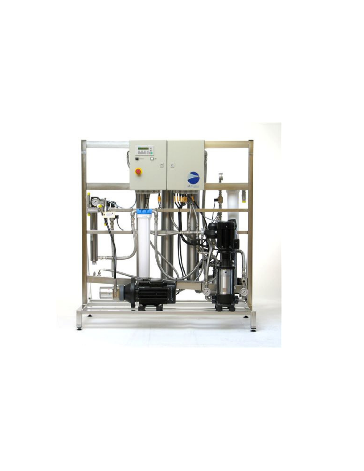
Control of the system, MLP RO pump station
Operating instructions
TI071GB-02 /06.11.09/LJ 1/12
Page 2

Table of contents
Humidification pump
Safety equipment
Selecting RO type
Choice of language
Normal indications
Alarm indications
Further indications
In the F1 area - Humidity
In the F2 area - Hour meters
In the F3 range - Indication of RO-status
Change of values
F5-F6-F7
3
4
5
5
7
7
8
8
8
8
9
9
In the F5 range - Scaling of sensors
In the F6 range - Common parameters
In the F7 range - Setting parameters for the humidity regulators
Reset to standard values
9
10
11
12
TI071GB-02 /06.11.09/LJ 2/12
Page 3

Humidification pump
The pump is driven by a three-phase motor powered by magnet controlled protective motor
switches. The control consists of a PLC-control system regulating the area humidity. The
regulation takes place by means of PI regulators to ensure a precise regulation of the area
humidity.
The PLC program is built up in such a way that you on the first start-up choose the number of
active sections. If e.g. three sections are chosen, section 4 is disconnected in safety circuits
and on display. On extensions, this choice can be repeated by using password 196.
In the control six hour meters are built in. One hour meter to indicate the operation time of
the pump to be used when determining the service intervals, one hour meter for the RO pump
and one hour meter for each of the four sections summarizing the humidification time.
TI071GB-02 /06.11.09/LJ 3/12
Page 4

Safety equipment
Pressure switch
The control is equipped with a locking device from the pressure switch placed on the inlet
side of the RO pump, ensuring that the pump stops if the water pressure disappears.
If the water pressure falls under shift pressure of the pressure switch, the display will
show alarm text. Restart is done by pressing “Alarm reset”.
Max hygrostat to secure against over-humidification
If the humidity rises to a value higher than the one adjusted on the max-hygrostat, the
system is stopped and the alarm lamp will light. The display shows in which section the
max-hygrostat is released.
The system has two possibilities for switching on after error (chosen in the F6 area).
If automatic switch on is chosen:
If the system, before switching off, has run for minimum one hour (adjustable) without
any MaxHygrostat error, it will be switched on automatically when the humidity is under
the set value again. If a new error appears before one hour has passed (adjustable) it will
not be switched on, but has to be switched on manually by pressing “Alarm reset”.
If manual switch on is chosen:
The system only restarts after acknowledge by pressing “Alarm reset”.
Thermostat
For protection of the high pressure pump the control is provided with a multi-stage
measurement of temperature.
Phase sequence relay
The control is equipped with a phase sequence relay securing against wrong connection of
the power cable. Both light-emitting diodes on relay E1, which is placed in the cabinet on
the right, must light.
In case of light in both diodes, the pumps will operate in the right direction. The relay also
secures against safety break.
TI071GB-02 /06.11.09/LJ 4/12
Page 5

Selecting RO type
The software of the control is made universally as to language choice choice of MLP ROtype. The choice of RO-type takes place at the first pass by the fact that VERS RO xxx 1003
appears on the display.
Here you choose between different options. (Options are only possible together with the
hardware changes)
Selecting options
You can choose between following options
- Load-dependent by-pass - fan control - raw water mixer.
The choice takes place as to the diagram below.
The screen will display VERS. 60_0 . Then press “Enter”. The cursor will now
blink under 0. Use the arrow keys to make the choice followed by “Enter”
60 0 60 1 60 2 60 3 60 4 60 5 60 6
Load-dependent by-pass
Raw water mixer
Fan control
X X X
X X X
X X X
Selecting language
Having chosen RO-type, language choice must be made. The display shows LANGUAGE
1/3 xxx - where the variable is set to 1 - for DANISH - 2 - for ENGLISH - 3 - for GERMAN.
Version 60 0 rel 1006 >
To be used for 1 department with pressure release valve or for 4 departments with solenoid
valve sets.
This has to be set up during the initial start.
Ex.1: 1 department with pressure release valve on the pump station:
Choose version: 60 X
Choose number of departments: 1
Press 2 for English
Press 0 for no membrane flush during start
Press F5
Type in password: 8599
Choose 0 at Valve set (default is 1)
TI071GB-02 /06.11.09/LJ 5/12
Page 6

Ex. 2: 3 departments with 3 solenoid valve sets
Choose version: 60 X
Choose number of departments: 3
Press 2 for English
Press 0 for no membrane flush during start
After having chosen type, language and options these only can be altered by typing the
PASSWORD 8599. It is also possible to reset the whole system to the default settings by first
activating the emergency stop and the deactivate it and holding the rest button for at least 25
seconds.
Using the password 8599 gives the possibility to change the membrane flush time. These may
not be altered by others than authorized personnel from ML System a/s. If ML System a/s
detects that the flush time has been altered all guarantee for the membrane will become void.
The control panel
The control system consists of a Siemens PLC 200-S7 and a control panel Siemens TD200.
The control panel is used to show actual values and to change the various parameters used in
the calculations of the control system.
The display shows the messages in two lines. If there are more than two messages, a flashing
arrow - up or down - will mark that there are more messages. By pressing the arrow keys up /
down you can scroll through the messages.
If you want to change a value, the cursor is placed on the desired line and you press enter. If
the value is protected by a password, the display asks for password, and the values are
changed by using the key arrows till you reach the desired value, and then press enter.
When the password is entered, the control system shows the actual value, and you can change
with the key arrows up/down. When the desired value is reached, press enter, and the desired
value will be entered in the control system.
The display is constructed with four F-keys which combined with the SHIFT key make eight
areas for output and changes of values. The keys F4 and F8 are only used as reset keys.
The functions in F1-F2-F3 are reached by pressing the key directly. The F5-F6-F7 are
reached by pressing SHIFT - now a flashing “S” appears in the lowest right corner. Now you
can press the actual F key.
The display is in standard mode when none of the F-keys have been chosen. You press an Fkey for example to read or change values.
You return by pressing alarm reset or another F-key.
Anyhow the display returns to standard mode after five minutes.
TI071GB-02 /06.11.09/LJ 6/12
Page 7

Password:
The setups in F5-7 are protected by password as described in the following.
If you need to use it, the display writes
PASSWORD 0
Another password for which you can be presented is when the display writes
PASSWORD REQUIRED
PASSWORD 0xxx
Here it is a password in order to enter and change the setup of the display for communicating
with the PLC unit. The setup may by no means be changed.
You get out of this and back to normal setup by pressing the ESC key.
Normal indications
Indication in display Explanation Range Standard
HUM. SECT.1 xx %RH The humidity in % of the section
concerned
HUM. SECT.2 xx %RH The humidity in % of the section
concerned
HUM. SECT.3 xx %RH The humidity in % of the section
concerned
HUM. SECT.4 xx %RH The humidity in % of the section
concerned
Alarm indications
Indication in display Explanation Range Standard
- ALARM - System in alarm - is always shown
together with one of the following:
MLPRO > 500
PUMP TOO HOT
MLPRO < 800
PUMP HOT - EMPTYING
SENSOR xx The signal from the sensor of the
INLET PRESSURE LOW The inlet pressure of the system has
MAX.HYG xxx The max-hygrostat of the section
OVERFLOW The tank is overfilled. Recouple by
The temperature of the pump is too
high. Wait for the tank to cool and
reset by pressing the reset-key
The temperature of the pump is too
high. The tank is emptied and the
system automatically switches on
again.
section concerned is outside the range.
The section is switched off, but will
automatically be switched on when the
signal is within the range again.
been under the shift pressure of the
pressure switch. Correct the error and
recouple by pressing the reset-key.
concerned has exceeded the set
humidity. Recouple by pressing the
reset-key.
pressing the reset-key when the water
level has dropped. Control the stop
point of the level bar.
TI071GB-02 /06.11.09/LJ 7/12
Page 8

Further indications
In the F1 area - Humidity
Indication in
display
SP1 xx %RH The desired humidity of the section concerned 0-MAX.SP 50
SP2 xx %RH The desired humidity of the section concerned 0-MAX.SP 50
SP3 xx %RH The desired humidity of the section concerned 0-MAX.SP 50
SP4 xx %RH The desired humidity of the section concerned 0-MAX.SP 50
Note: SP x = 0 describes that FLU (see description under the F7 range) is put out of operation.
In the F2 area - Hour meters
Indication in display Explanation Range Standard
SECT. 1 x.x HOUR
SECT. 2 x.x HOUR
SECT. 3 x.x HOUR
SECT. 4 x.x HOUR
PUMP x.x HOUR
PUMP RO x.x HOUR
Explanation Range Standard
Indication of the time humidified in
the individual section
Indication of the time humidified in
the individual section
Indication of the time humidified in
the individual section
Indication of the time humidified in
the individual section
Indication of the total operating time
of the pump.
Indication of the total operating time
of the RO pump.
In the F3 range - Indication of pump temperature
Indication in display Explanation Range Standard
MLPRO > 500
PUMP TEMP xxxx °C
Indication of the pump working
temperature in °C
TI071GB-02 /06.11.09/LJ 8/12
Page 9

Change of values
F5-F6-F7
Indication in display Explanation Range Standard
PASSWORD xxxx Password for changing values.
The password for changing operating parameters in F5-F6-F7 is 197.
If the password is set to 196, a text is shown in the display saying that the number of active
sections can be changed between 1-4.
The password is reset again by pressing the reset-key.
In the F5 range - Scaling of sensors
Indication in display Explanation Range Standard
1-HIE x.xx *LOE x.xx HIE - Highest electric signal from the
humidity sensors.
LOE - Lowest electric signal from the
humidity sensors.
1-HI xx *LO xx HI - Indication at the highest electric
signal.
LO - Indication at the lowest electric
signal.
2-HIE x.xx *LOE x.xx HIE - Highest electric signal from the
humidity sensors.
LOE - Lowest electric signal from the
humidity sensors.
2-HI xx *LO xx HI - Indication at the highest electric
signal.
LO - Indication at the lowest electric
signal.
3-HIE x.xx *LOE x.xx HIE - Highest electric signal from the
humidity sensors.
LOE - Lowest electric signal from the
humidity sensors.
3-HI xx *LO xx HI - Indication at the highest electric
signal.
LO - Indication at the lowest electric
signal.
4-HIE x.xx *LOE x.xx HIE - Highest electric signal from the
humidity sensors.
LOE - Lowest electric signal from the
humidity sensors.
4-HI xx *LO xx HI - Indication at the highest electric
signal.
LO - Indication at the lowest electric
signal.
1,00 - 25,00
0 - 20,0
10 - 200
0 - 200
1,00 - 25,00
0 - 20,0
10 - 200
0 - 200
1,00 - 25,00
0 - 20,0
10 - 200
0 - 200
1,00 - 25,00
0 - 20,0
10 - 200
0 - 200
197
V - 8,00
MA - 4.20
V - 2,00
MA - 1,80
80,0
20
V - 8,00
MA - 4.20
V - 2,00
MA - 1,80
80,0
20
V - 8,00
MA - 4.20
V - 2,00
MA - 1,80
80,0
20
V - 8,00
MA - 4.20
V - 2,00
MA - 1,80
80,0
20
TI071GB-02 /06.11.09/LJ 9/12
Page 10

however max.
In the F6 range - Common parameters
Indication in display Explanation Range Standard
MAX.SP xx %RH The maximum limit for adjustment of
the set points.
INTEGRATION xx MIN Time indication before the integration
regulation is 100%
PRESSOSTAT x.x SEC Time delay of missing water pressure 0-10,0 20,0
FAN.CONTR. xx 0/2
(OPTION)
MAX.HYG.AUT 0/1 xxxx Choice of reset function for Max
MLPRO > 500
TEMP LIMIT1 xxxx °C
MLPRO > 500
TEMP LIMIT2 xxxx °C
MLPRO > 500
TEMP LIMIT3 xxxx °C
AUT.HYG.TIME xx.x SEC Settting the security time for
RV.MIX.MODE 0/1 xxxx
(OPTION)
Bypass < xx l/t
(OPTION)
Choice of function for the fan control
of the humidifying modules.
(0) No fan automatic
(1) Automatic control
(2) The fans are operating constantly
Hygrostat security.
(0) Manual reset
(1) Automatic reset once an hour.
The limit value for step 1 of the
temperature protection. The system
will start producing fresh RO-water if
this limit is exceeded. This function
only runs once every 12 hours.
The limit value for step 2 of the
temperature protection. The bypass
valve of the pump will open and flush
the water if this limit is exceeded.
The limit value for step 3 of the
temperature protection. The pump will
stop if this limit is exceeded and will
not start before the system has cooled
down and is re-started.
automatic reset of Max Hygrostatcircuit.
Choice of active raw water mixer
(0) Not active
(1) active
Setting the opening level of the
bypass fan
40-90 60
0-100 25
0-2 0,0
0-1 0
10-60 30
10-60 40
10-60 50
0-10,0 1,0
0-1 0,0
0-1000 60,0
TI071GB-02 /06.11.09/LJ 10/12
Page 11

In the F7 range - Setting parameters for the humidity regulators
Indication in display Explanation Range Standard
1*PRO xx - PER xx.x PRO - Proportional belt for humidity
regulation of the section
PER -The period (a pulse & and a
pause) in the section indicated in
seconds.
1*MON xx.x -PAU xx.x MON - The lowest pulse time during
which can be humidfied in the section.
(If the calculated time is less, the time
is added to the calculation for the next
period). Time is indicated in seconds.
PAU -The time of the forced pause
that minimum is held in each period.
The time is indicated in seconds.
1*FLU xx.x - FLOW xx FLU -The minimum time during
which the section humidifies to ensure
exchange of water in the hoses. The
operation time is set in minutes per 30
minutes.
FLOW - The capacity in the section in liter per hour
2*PRO xx - PER xx.x PRO - Proportional belt for humidity
regulation of the section
PER -The period (a pulse & and a
pause) in the section indicated in
seconds.
2*MON xx.x -PAU xx.x MON- The lowest pulse time during
which can be humidfied in the section.
(If the calculated time is less, the time
is added to the calculation for the next
period). Time is indicated in seconds.
PAU -The time of the forced pause
that minimum is held in each period.
The time is indicated in seconds.
2*FLU xx.x - FLOW xx FLU -The minimum time during
which the section humidifies to ensure
exchange of water in the hoses. The
operation time is set in minutes per 30
minutes.
FLOW - The capacity in the section in liter per hour
3*PRO xx - PER xx.x PRO - Proportional belt for humidity
regulation of the section
PER -The period (a pulse & and a
pause) in the section indicated in
seconds.
3*MON xx.x -PAU xx.x MON- The lowest pulse time during
which can be humidfied in the section.
(If the calculated time is less, the time
is added to the calculation for the next
period). Time is indicated in seconds.
PAU -The time of the forced pause
that minimum is held in each period.
The time is indicated in seconds.
0-50
10-1000
0-50,0
1-200,0
0-2,0
0-1000
0-50
10-1000
0-50,0
1-200,0
0-2,0
0-1000
0-50
10-1000
0-50,0
1-200,0
20
60,0
5,0
10,0
0,2
50
20
60,0
5,0
10,0
0,2
50
20
60,0
5,0
10,0
TI071GB-02 /06.11.09/LJ 11/12
Page 12

3*FLU xx.x - FLOW xx FLU -The minimum time during
which the section humidifies to ensure
exchange of water in the hoses. The
operation time is set in minutes per 30
minutes.
FLOW - The capacity in the section in liter per hour
4*PRO xx - PER xx.x PRO - Proportional belt for humidity
regulation of the section
PER -The period (a pulse & and a
pause) in the section indicated in
seconds.
4*MON xx.x -PAU xx.x MON- The lowest pulse time during
which can be humidfied in the section.
(If the calculated time is less, the time
is added to the calculation for the next
period). Time is indicated in seconds.
PAU -The time of the forced pause
that minimum is held in each period.
The time is indicated in seconds.
4*FLU xx.x - FLOW xx FLU -The minimum time during
which the section humidifies to ensure
exchange of water in the hoses. The
operation time is set in minutes per 30
minutes.
FLOW - The capacity in the section in liter per hour
0-2,0
0-1000
0-50
10-1000
0-50,0
1-200,0
0-2,0
0-1000
0,2
50
20
60,0
5,0
10,0
0,2
50
Reset to standard values
All settings can be reset to standard settings by pressing emergency stop for at least 10
seconds.
Then the emergency stop is loosened while the red reset key is pressed, the display writes
after approx. 5 sec. INITIALIZING. Then you can release the reset key
TI071GB-02 /06.11.09/LJ 12/12
 Loading...