

Your guide to selecting and specifying Nortec evaporative humidifiers / air coolers
2558982-D | 24 OCT 2011
MH
Series
Engineering
Manual
Includes technical specifications,
guidelines, and options for selection
and application of MHTC / MHB
Evaporative humidifiers / air coolers

Thank you for choosing Nortec.
Proprietary Notice
This document and the information disclosed herein are proprietary data of WALTER MEIER LTD. Neither this
document nor the information contained herein shall be reproduced, used, or disclosed to others without the
written authorization of WALTER MEIER LTD., except to the extent required for installation or maintenance of
recipient’s equipment. All references to the Nortec name should be taken as referring to WALTER MEIER LTD.
Liability Notice
Nortec does not accept any liability for installations of humidity equipment installed by unqualified personnel or
the use of parts/components/equipment that are not authorized or approved by Nortec.
Copyright Notice
Copyright 2011, WALTER MEIER LTD. All rights reserved.

Contents
1 Introduction
1 The MHTC/MHB Evaporative
Humidifier / Air Cooler
1 How the MH works
2 Humidification / Cooling
4 MH Models
6 MH Humidifier Features
7 MH Components
9 MH Specifications and
Dimensions
13 Specifying the MH
14 MH Specification Checklist
15 MH Model
29 MH Installation
Requirements
30 Location – Duct Module
31 Location – MHTC Reflow
Hydraulic Unit
32 Plumbing
34 Electrical
35 MHTC/ MHB Controls
39 Control Wiring
36 Nortec Controls
39 Control Location
41 Nortec Links XPS (MHTC Only)
44 Warranty
15 Duct Module Size
15 Number of Stages
15 Media Boxes Thickness
17 Humidification Load
19 Specifying for Air Cooling
21 MH Controls
21 MH Series Options and
Accessories
24 Sample Specification
The MHTC/MHB Evaporative Humidifier / Air Cooler
The MHTC / MHB is an evaporative type humidifier / air cooler that provides humidifier and
cooling adiabatically. The MHTC/MHB uses evaporative media that is placed in the air stream
of an air handler or duct. The media is wetted with potable, RO, or DI water. The energy in the
air passing through the media evaporates some of the water. The result is an increase in the
humidity of the air and a decrease in the temperature of the air.
The main applications of MH series humidifiers / air coolers are either humidification of
buildings which have a high humidification load and which can also benefit from the adiabatic
cooling effect or simply the adiabatic cooling of air for building temperature control. Since the
MH depends on the energy in the air passing through the evaporative media to evaporate water,
the MH requires inlet air that is warm and dry for most efficient operation.
MH Media
One of the most unique features of all MH series humidifiers / air coolers is their patented
synthetic v-profile evaporative media which does not break down over time and release
microscopic fibers which could be a health hazard. In addition the MH media is treated with an
antimicrobial agent and meets UL900 Class 1 flame and smoke in the USA, ULC-S111-07 Class
2 in Canada making it the best media available for evaporative humidification / air cooling.
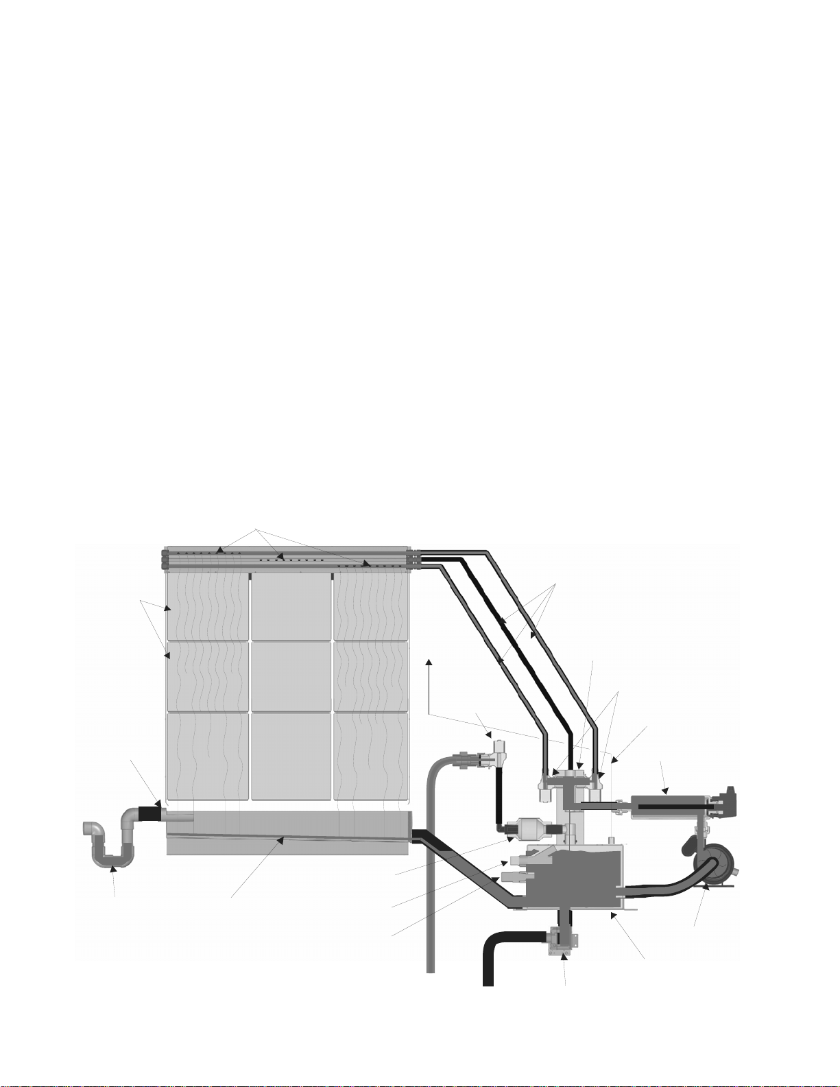
How the MH works
Media
Boxes
Overflow
Spray Bars
Stage 1 Stage 2 Stage 3
Check Valve
To duct
Fill Valve
Spray Bar Lines
Staging Manifold
Staging Valve s
Pressure
Equaliza t ion line
UV Light
P Trap
Drain Pan
1 | The Nortec MHTC / MHB
Float
Conductivity
Sensor
Drain
Figure 1: MHTC Reflow Schematic
Pump
Reservoir
Drain Valve
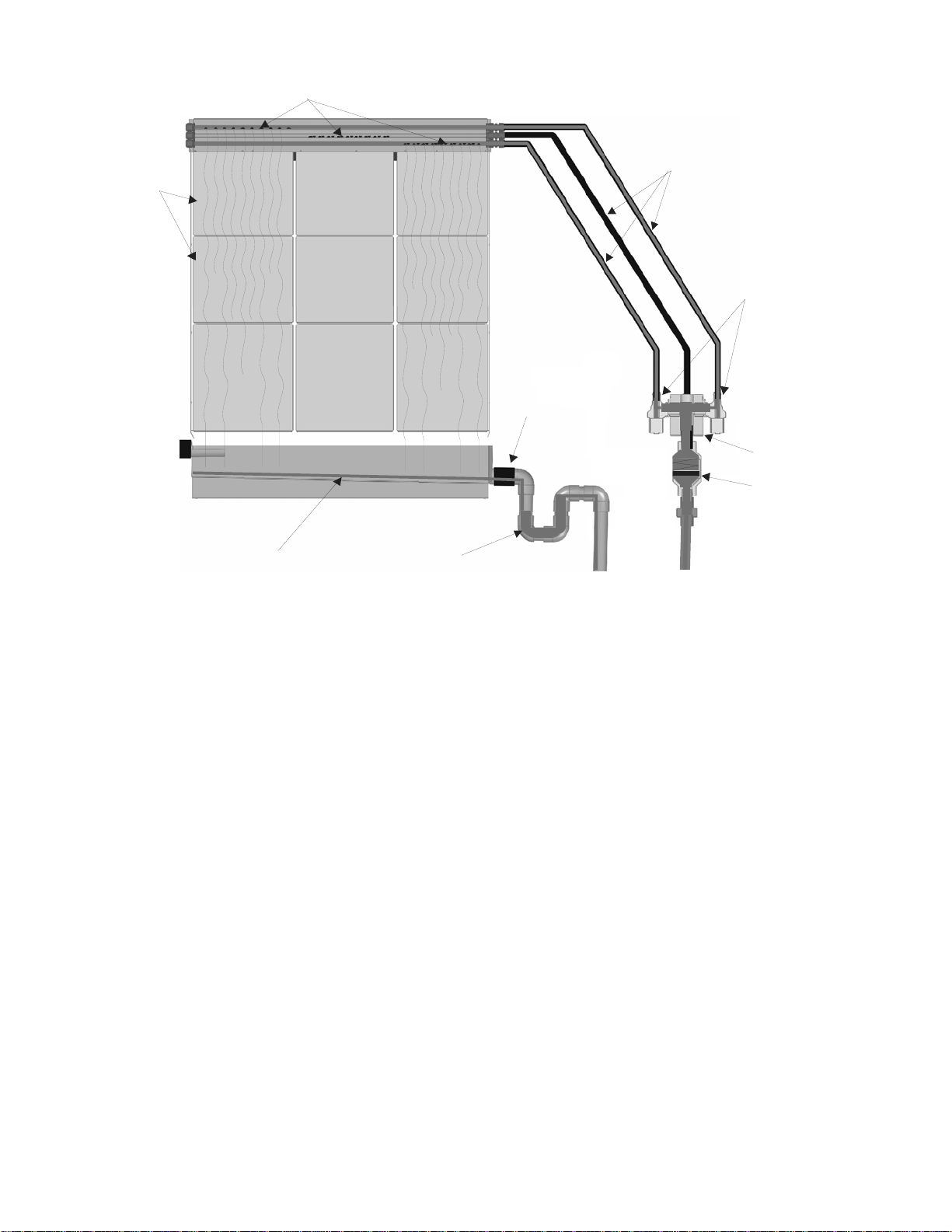
d
Spray Bars
Media
Boxes
Stage 1 Stage 2 Stage 3
Drain Pan
P Trap
Spray Bar Lines
Staging Valves
Drain
Staging Manifol
Check Valve
Figure 2: MHTC Flow / MHB Schematic
Humidification / Cooling
When a demand is received, the MH will;
MHTC Reflow - turn on its pump and UV light and after a short delay activate staging valves
as required to meet demand. Water will flow through the UV light, staging manifold, open
staging valves, and spray bar lines to the spray bars.
MHTC Flow / MHB – Activate staging valves as required to meet demand. Water will flow
through the staging manifold, open staging valves, and spray bar lines to the spray bars.
Each spray bar has a series of holes which allow water to flow out over a section of
evaporative media. As Water runs down the evaporative media some of it is evaporated by
air passing through the media. As a result of the evaporation the humidity of the air is
increased and the temperature of the air is decreased.
Any water that is not evaporated collects in the drain pan and;
MHTC Reflow - flows back to the hydraulic unit reservoir to be recirculated. As water is
evaporated the water level in the reservoir decreases and the float opens. The MH then
refills until the float is closed.
MHTC Flow / MHB – flows down to drain. The MHTC Flow / MHB does not have a reservoir
or pump and water simply flows through the staging valves when they are open using supply
water pressure to generate flow.
During operation the controller responds to changes in demand by opening and closing
staging valves. This allows the MH to match its output to demand.
The Nortec MHTC / MHB | 2

When demand is satisfied the MH will;
MHTC Reflow – turn off all staging valves and after a delay turn off the UV light and pump.
MHTC Flow / MHB – turn off all staging valves.
Water Management (MHTC Reflow only)
During the evaporation process minerals are left behind by the evaporated water resulting in
an increase in concentration in the remaining water. To prevent minerals from collecting in
and fouling the evaporative media more water is supplied to the media than can be
evaporated. The unevaporated water carries the minerals left by evaporated water to the
reservoir.
To prevent the mineral concentration from increasing to the point where excess water can
no longer dissolve minerals left in the media by evaporated water, the MH will periodically
flush the reservoir. The method used to determine when to flush the tank is configured
using display and keypad. Two triggers can be set.
Trigger 1
Time – The MHTC flushes the tank at a specific time every day.
Periodic – The MHTC flushes the tank after a fixed number of operating hours.
Demand - The MHTC flushes the tank after a fixed number of weighted hours ( weighted
hours = hours of operation x demand% )
Trigger 2
Cycle – The MHTC flushes the tank after a fixed number of fill cycles.
μSSensor (requires optional conductivity sensor)– Flushes the tank when the conductivity
sensor indicates the concentration of minerals exceeds a configured maximum value.
In general more frequent drains result in less maintenance. The amount of water drained to
control mineral concentration in the recirculating water can be configured in the MHTC’s
software.
Pressure Equalization Line (MHTC Reflow only)
In order to ensure that water flows properly from duct module’s drain pan to the MHTC Reflow’s
reservoir a pressure equalization line must be installed between the reservoir and the duct
down stream of the duct module. The line ensures pressure in the reservoir and duct are equal
and water flows properly from the drain pan to the reservoir.
UV Light
A UV light is standard on the MHTC Reflow and optional on the MHTC Flow / MHB. The UV light
prevents bacteria in the supply water or reservoir from being introduced into the evaporative
media. It does not kill bacterial that may be introduced into the media in the air stream.
Box Drying / Box Washing
In order to prevent bacteria from growing in the evaporative media the MH includes a box drying
cycle that allows the media to dry out. The MH will periodically close all staging valves and allow
the media to dry out regardless of demand.
In order to wash minerals from and prolong media life the MH includes a wash cycle which turns
on all staging valves regardless of demand or control status and rinses the media.
3 | The Nortec MHTC / MHB
MH Models
The MH2 is available in three models (see Figure 3: MH Models and Table Table 3: MH
Specifications).
MHTC Reflow - provides state of the art control technology with staged output to match
demand. The Reflow model also includes a hydraulic unit that provides maximum water
conservation by recirculating unevaporated water.
MHTC Flow - provides the same state of the art control technology including staging of
output to match demand but without the hydraulic unit for recirculating water.
MHB - provides basic operation without any user configurable features.
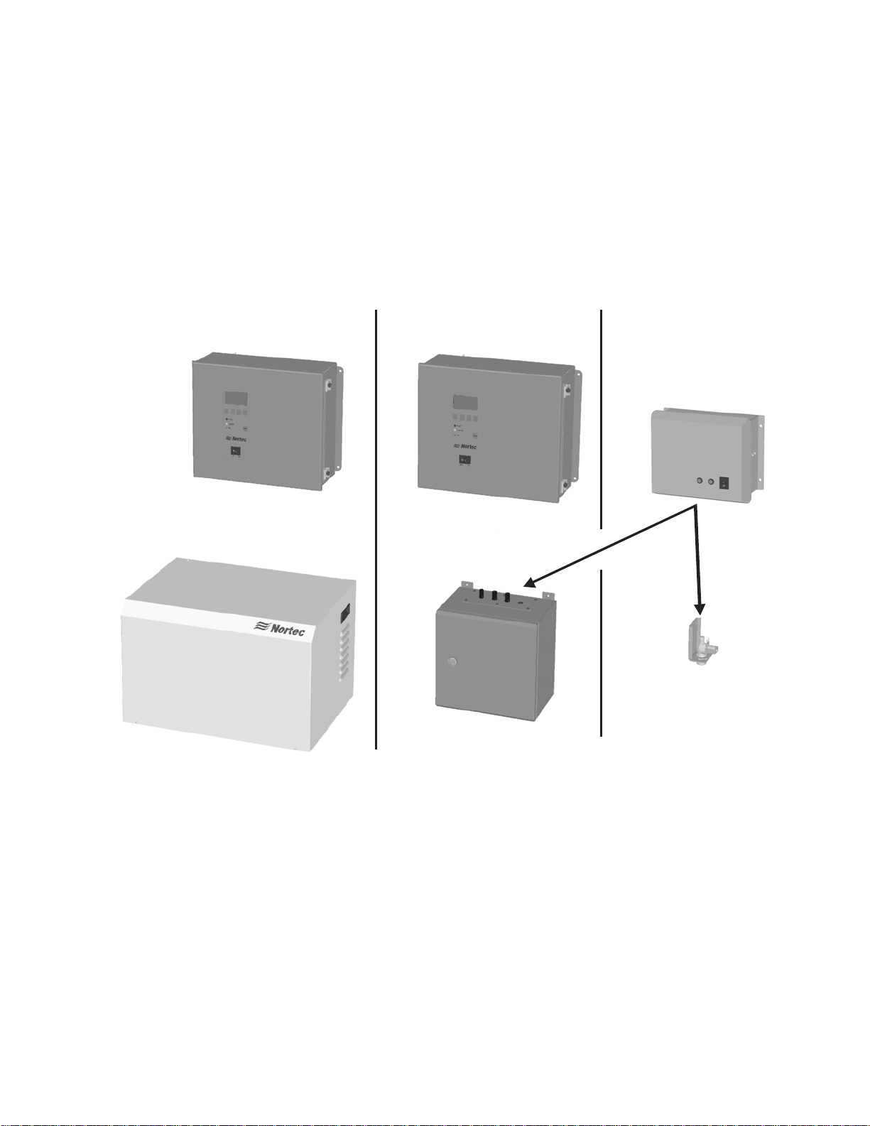
MHTC Reflow MHTC Flow MHB
OR
Single StageMult i S t age
Figure 3: MH Models
Each MH model is coupled with a duct module that contains the evaporative media used for
humidifying / cooling the duct air. The duct module is basically the same for each model with
the exception of the number of spray bars which are used for staging output.
The Nortec MHTC / MHB | 4
MHTC Reflow vs MHTC Flow and MHB
All units run a small excess of water over the media during operation to wash minerals away
and prolong media life. The MHTC Flow and MHB direct this water directly to drain, while the
MHTC REflow recaptures and reuses the water. The REflow is the most water efficient model
and recommended for good quality potable water and treated water types. Flow models are
recommended for areas with hard potable water, or where a central wastewater recovery
strategy is being used. See Table 1: MHTC Reflow / MHTC Flow / MHB Features for a listing of
the additional features provided by the MHTC Reflow.
MHTC Flow vs MHB
The main difference between the MHTC Flow and the MHB model is in their controls and user
interface. The MHTC model’s Total Controller provides a graphic LCD screen and keypad,
accepts additional control signals and has optional building management system connectivity
(BACnet, Lonworks, Johnson N2, and Modbus). The MHB controls provide the basic
functionality required for operation. See Table 1: MHTC Reflow / MHTC Flow / MHB Features
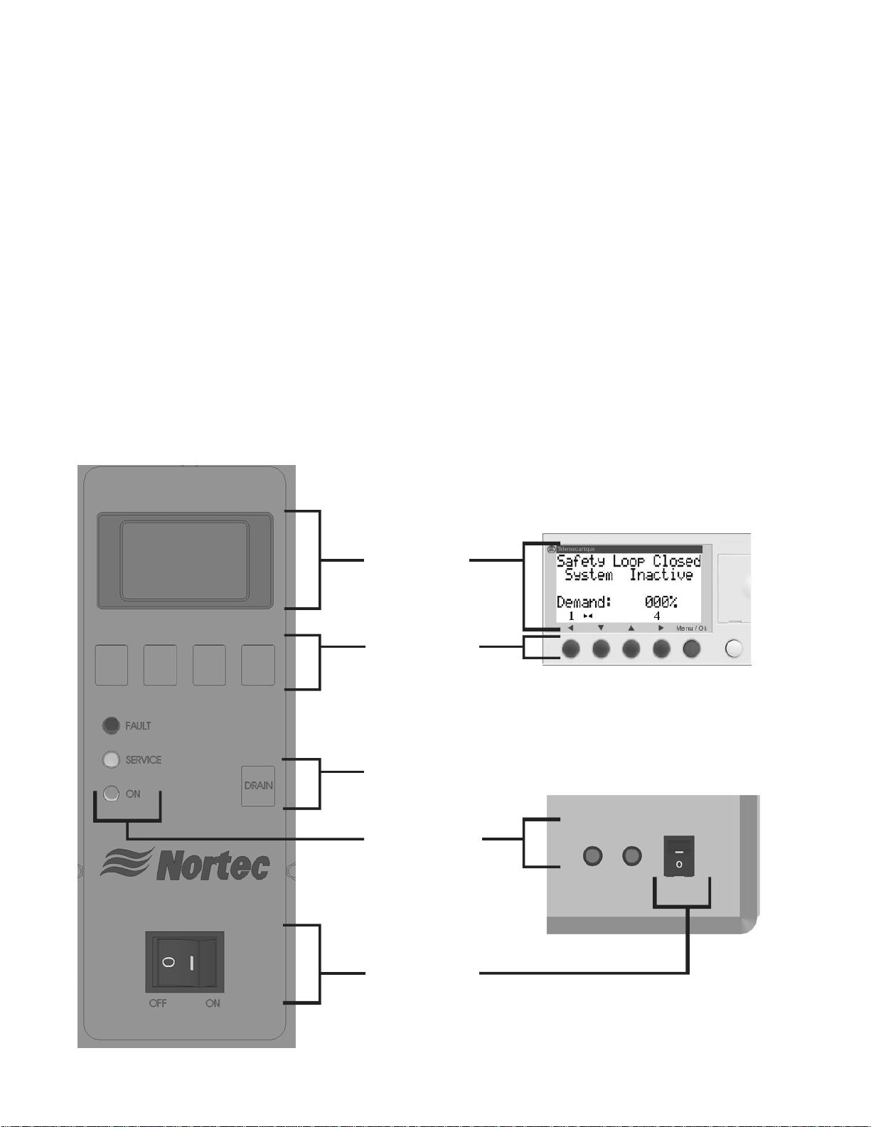
for a listing of the two control systems features. Figure 4 shows the differences in the MHTC’s
and MHB’s user interface.
MHTC
MHB
LCD Display
Inside Control Box
Input Buttons
(MHTC used to
navigate screens
and for configuration,
MHB for factory
configuration only.)
Sof tware Drain
Button
(Initiates a software
controlled drain)
Status LEDs
Lights
Outside Control Box
5 | The Nortec MHTC / MHB
On/Off Switch
(Turns humidifier
On/Off)
Figure 4: MHTC and MHB User Interfaces

The MHTC LCD screen and keypad - allow easy configuration of all features of the MHTC
humidifier such as control signals, box washing / drying, tank flushing, maintenance reminders,
and others. The LCD screen also provides status information indicating current status and
configuration, service and fault messages, and troubleshooting information. One of the key
features of the MHTC controller is tracking operation and providing information about service
requirements to make it easy to service and maintain the MHTC.
MH Humidifier Features
From their patented evaporative media and modular design to the MHTC’s advanced control
system with optional internet based monitoring capability to the MHTC Reflows advanced water
conservation technology all MH models include many advanced features that set them apart
from other evaporative humidifiers / air coolers. The following list outlines some of the MH
series key features.
Table 1: MHTC Reflow / MHTC Flow / MHB Features
General MHTC Reflow MHTC Flow MHB
Patented synthetic V-profile evaporative media
Stainless steel duct / media box frames, and drain pan
Operates on DI/RO, Potable, Softened Water
Optional low pressure drop mist eliminator
Recirculating water system
Direct water system
Wash cycles and box drying
Step-Control 1,2, or 3 stage
Ultra violet water treatment
Installation / Maintenance
All electrical components outside of duct
Modular easy to change media boxes
Programable maintenance settings
Wide range of water management options
Electronics
Graphic display screen with keypad input
LED status indicators
Remote status via dry points
Staged output based on modulating signal
Proportional and integral internal control from humidity
sensor inputs
Manual capacity adjustment
On/Off operation
Compatible with all standard Industrial controls
BMS (Lonworks, BACnet, Johnson, Modbus)
Other
UL900 Class 1 Flame and Smoke USA
ULC-S111-07 Class 2 Flame and Smoke Canada X X X
X X X
X X X
X X X
Optional Optional Optional
X
X X
Configurable Configurable Factory Set
X X X
X Option Option
X X X
X X X
X X
X
X X
X X (2 lights)
X X
1-3 Stages 1-3 Stages 1 stage
X X
X X
X X X
X X
Option Option
X X X
The Nortec MHTC / MHB | 6
V
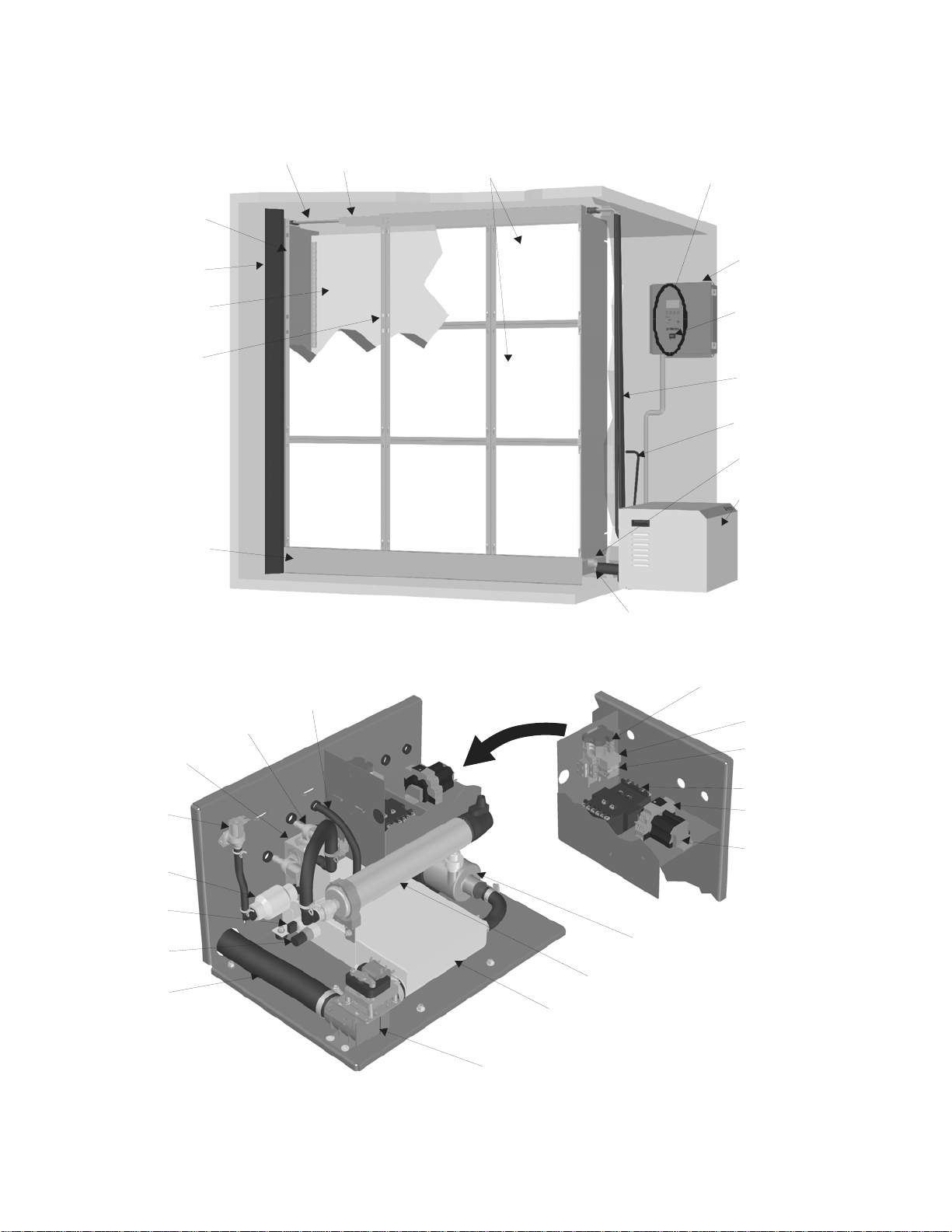
MH Components
Spray
Bars
Right
Side Panel
Duct Seal
Mist
Eliminator
Intermediate
Member
Drain
Pan
Equalization
Staging
Staging
Manifold
Fill
Valve
Check
Valve
Float
Conductivity
Sensor
Drain Outlet
Valve
7 | The Nortec MHTC / MHB
Pressure
Line
Spray Bar
Cap
Media Boxes
Reservoir
Drain Valve
Figure 5: MH Humidifier Components
Display and Keypad
Control
Box
On/Off Switch
Water Lines
Pressure
Equalization
Line
Drain
Overflow
Hydraulic
Unit
Drain Pan Drain
High Voltage
Terminal Block
Fuse Bloc k
Pump and U
Light Relay
Transformer
Conductivity
Transmitter
Low Voltage
Terminal
Block
(Hydraulic
Uni t )
Pump
UV Light

f
Description of Components
Table 2: Humidifier Components
Component Function of Component
Check Valve Provides back flow protection for supply water line.
Conductivity Sensor
/Transmitter
Control Box /
Display and Keypad
Drain Pan Collects unevaporated water from media for recirculation or draining.
Drain Pan Drain Drain pan connection to hydraulic unit reservoir.
Drain Outlet Drain connection from the hydraulic unit.
Drain Overflow Provides protection from overfilling the drain pan.
Drain Valve Drains water from the reservoir.
Duct Seal Prevents duct air flow from bypassing the humidifier.
Fill Valve Controls makeup water flow to humidifier based on float level.
Float Measures water level in reservoir to prevent over filling.
Fuse Block Overcurrent protection for pump and UV light.
High Voltage
Terminal Block
Hydraulic Unit Collects water from the drain pan and pumps, treats with UV light, and
Intermediate
Member
Low Voltage
Terminal Block
Media Boxes Surface from which water is evaporated for humidification/cooling.
Mist Eliminator Captures any water droplets that are carried off the media boxes with air
On/Off Switch Turns power On/Off to humidifier controller. Note: Turn off humidifier
Pressure
Equalization Line
Pump Pumps water from the reservoir to the media boxes.
Pump and UV Light
Relay
Reservoir Collects water from the drain pan for recirculation / draining.
Side Panel, Right Structural member supports media boxes and spray bar cap.
Spray Bar Cap/
Spray Bars
Staging Manifold /
Valve(s)
Transformer Steps primary voltage down to 24 VAC for the controller and internal
UV Light Eliminates any bacteria in the water being pumped to the media boxes.
Water Lines Supply water lines from hydraulic unit to spray bars.
Sensor measures conductivity of water in the reservoir. Transmitter
sends measured value to control box for use in water quality control.
Controls all functions of the humidifier’s operation and provides user
interface for configuration of the humidifier.
Primary voltage connection on hydraulic unit and in control box.
stages water to media. Fills and drains reservoir to control water quality.
Structural member supports media boxes.
Hydraulic Unit – connects control box inputs to the hydraulic unit.
Control Box – provides connection for control signals and safety loop.
Available in 8 in. (20 cm) or 12 in. (30 cm) thickness.
flow in high duct speed applications.
disconnect to shut off primary power to the humidifier.
Balances pressure in hydraulic unit reservoir with pressure in duct to
ensure proper water flow to reservoir from drain pan.
Turns on power to the UV light and pump based on signal from the
control box.
Distributes water to the media boxes and prevents water from spraying
anywhere else.
Controls flow o
water to media boxes based on demand.
components such as the fill valve and drain valve.
The Nortec MHTC / MHB | 8

t
t
MH Specifications and Dimensions
Table 3: MH Specifications
Voltage
Control signals
Max No. of Stages
Water supply
Water drain
Control accuracy
Supply water pressure
Supply water temperature
Water quality
Max. allowable air velocity through
media
Pressure drop
Ambient conditions (control unit)
Fire classification of evaporative media
MHB
120 VAC / 60 Hz 120 VAC / 60 Hz 120 VAC / 60 Hz
On/Off
Dry set of points
3 3 3
3/4 in. BPP, 1/2 in.
NPT adapter provided
2 in. (50.8 mm) OD
ube
Depends on air conditions, number of stages, and control setup
30-145 psi (2-10 Bar)
Tap water, reverse osmosis, softened or fully demineralized water.
1100 fpm (5.5 m/s) with mist eliminator.
Typically 0.44 IWC (250 Pa) @ 500 fpm (2.5 m/s) and 90% RH
34 –104 ºF (1- 40 ºC) Max 75% RH
UL900 Class 1 USA, ULC-S111-07 Class 2 Canada
MHTC
Flow
VDC 0-5, 1-5, 0-10,
2-10, 0-16, 3.2-16
mA 0-20, 4-20
1/2 in/ FPT 3/4 in. BPP, 1/2 in.
NPT adapter provided
2 in. (50.8 mm) OD
ube
41-113 ºF (5-45 ºC)
750 fpm (3.8 m/s)
MHTC
Reflow
VDC 0-5, 1-5, 0-10,
2-10, 0-16, 3.2-16
mA 0-20, 4-20
2 in (50.8 mm) ID
hose
4 x 5/16 in
(8 mm)
12.0 in.
30.5 cm
O
16.7 in.
42.5 cm
17.5 in.
44.4 cm
Figure 6: MHTC Reflow/Flow Control Box Dimensions
6.2 in.
15.6 cm
14.3 in.
36.3 cm
9 | The Nortec MHTC / MHB
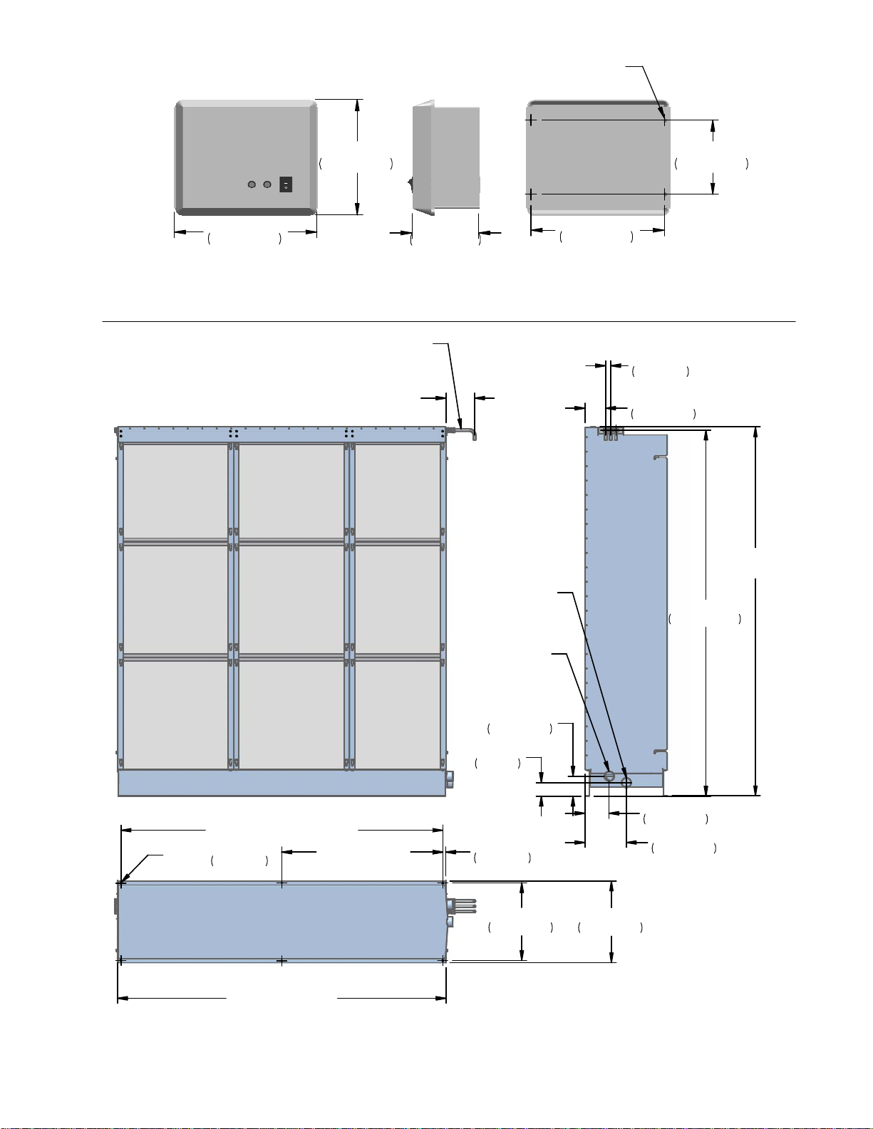
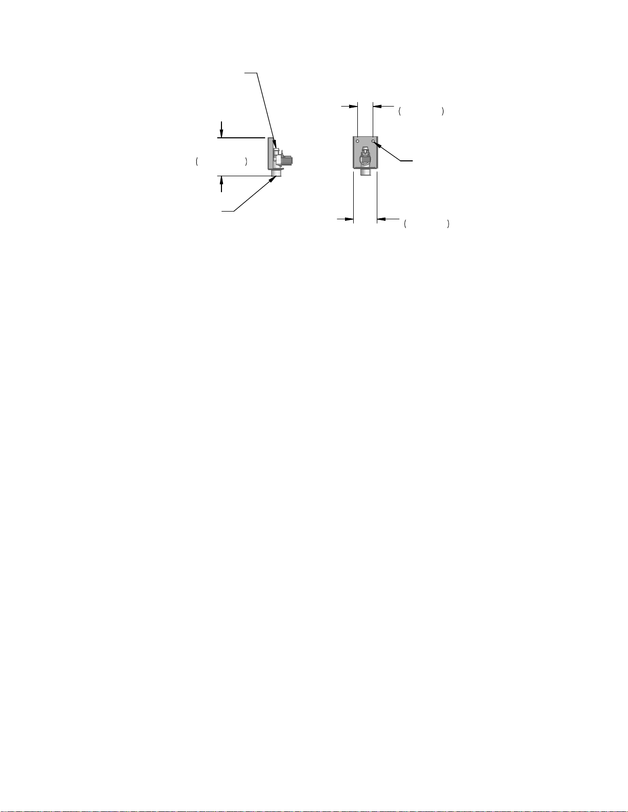
4 x 0.31 in.
(8 mm)
O
9.3 in.
23.6 cm
11.5 in.
29.2 cm
5.4 in.
13.6 cm
6.0 in.
15.2 cm
10.75 in.
27.3 cm
Figure 7: MHB Control Box Dimensions
12 in. (30 cm) Supplied
Cut to Desired Length
1-3 x Spray Bar
1/2 in. (12.7 mm)
Tube
1.0 in.
2.7 cm
TYP
4.2 in.
10.7 cm
2.0 in (50.8 mm)
2 in. (50.8 mm)
Drain
Tube
Overflow
Tube
H=24 - 144 in.
(0.6 - 3.7 m)
74.6 in.
189.6 cm
W - 1.2 in (W - 3.2 cm)
O
0.2 in.
0.6 cm
6 X
W/2 - 0.6 in.
(W/2 - 1.6 cm)
4.1 in.
10.3 cm
2.8 in.
7 cm
0.6 in.
1.6 cm
4.9 in.
12.5 cm
8.4 in.
21.5 cm
15.8 in.
40.2 cm
16.6 in.
42.3 cm
W = 24 - 144 in.
(0.6 - 3.6 m)
Figure 8: MH Duct Module Dimensions
The Nortec MHTC / MHB | 10
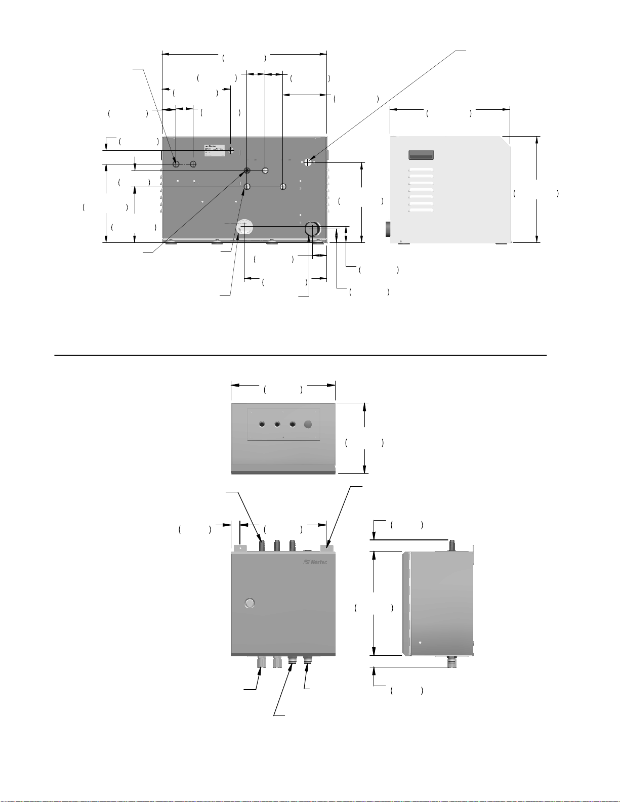
Electrical
3 x 7/8 in.
(22 mm)
11.5 in.
29.2 cm
Press. Equal.
1/2 in. (13 mm)
2.0 in.
5.2 cm
2.0 in.
5.1 cm
2.4 in.
6 cm
8.2 in.
20.8 cm
Hose Barb
2.6 in.
6.7 cm
10.0 in.
25.5 cm
2.5 in.
6.4 cm
Spray Bar
Connections
1-3 x 1/2 in.
(13 mm) Hose Barb
Drain Pan
Connection
2 in. Tube
24.1 in.
61.3 cm
2 in. ID Hose
2.1 in.
5.3 cm
12.1 in.
30.7 cm
Drain
2.6 in.
6.7 cm
6.4 in.
16.4 cm
11.8 in.
29.9 cm
2.4 in.
6.1 cm
2.0 in.
5.2 cm
Water Inlet
3/4 in BSP
(1/2 in. NPT
Adapter
provided)
17.6 in.
44.6 cm
15.6 in.
39.5 cm
Figure 9: MHTC Reflow Hydraulic Unit Dimensions
11.87
30.15
8.05
20.45
1 - 3 x 1/2 in. OD
Barbed Hose
1.00
2.55
9.87
25.07
2 x 1/4 in.
(6.4 mm)
O
1.31
3.33
11.88
30.16
2 x Water T ight
Electrical Connection
Figure 10: MHTC Flow/MHB Multi Stage Hydraulic Unit Dimensions
11 | The Nortec MHTC / MHB
Strain Relief
Drain
1/2 in. NPT
Water Inlet
1/2 in. NPT
1.32
3.36
Spray Bar
Connection
1/2 in (13 mm)
Hose Barb
1.8 in.
4.4 cm
4.3 in.
10.9 cm
2 x 0.3 in.
(7.6 mm)
O
Water Inlet
3/4 in GHT
2.7 in.
6.8 cm
Figure 11: MHB Single Stage Hydraulic Unit
The Nortec MHTC / MHB | 12

Specifying the MH
Humidifier / Air Cooler
14 MH Specification Checklist
15 MH Model
15 Duct Module Size
15 Number of Stages
15 Media Boxes Thickness
17 Specifying for Humidification
17 Humidification Load
17 Example: Mixed Air System
17 Example: Makeup Air System
18 Required Media Box Thickness for Humidification
19 Specifying for Air Cooling
19 Direct Air Cooling
20 Indirect Air Cooling
21 MH Controls
21 MH Series Options and Accessories
24 Sample Specification
13 | Specifying the MH Humidifier / Air Cooler

MH Specification Checklist
The following checklist can be used to specify the MH Series Humidifier / Air Cooler. A
description of each selection is provided later on in this section.
Unit Tag: _______________ Zone _______________
Location or Elevation
MH Model
MHTC Reflow MHTC Flow MHB
Duct Module Size
in. cm
Duct Width ______________ Duct Height
Number of Stages
1 2 3
Humidification
Air Before Humidification Temp RH
Air After Humidification Temp RH
Required Effectiveness
Air Cooling
Air Before Cooling DB Temp WB Temp
Air After Cooling DB Temp
Required Effectiveness
Media Box Thickness
Duct Velocity 8 in. (20 cm) Eff. 12 in. (30 cm) Eff.
Use 8 in. (20 cm) Media Use 12 in. (30 cm) Media
Control
Humidity
Demand Transducer On/Off Signal Type _______
By Others By Nortec, Part No_______________
or
Temperature
Demand On/Off By Others
Additional Options (Mist Eliminator, Links XPS, Air proving… See Table 6: Options and
Accessories)
_________________________________________________________________________________
_________________________________________________________________________________
Specifying the MH Humidifier / Air Cooler | 14

X
X
X
X
MH Model
The decision of which MH model to use depends primarily on the application, the need for
advanced control capabilities, and the need to minimize water usage. Table 4 provides an
overview of the items to consider when selecting the MH Model for your application.
Table 4: MH Model Selection
MH Model MHTC Reflow MHTC Flow MHB
Minimize water
usage
Treated water Best
Potable water X
Hard water X
BMS Control X
Humidification Best
Cooling
Low Cost
X
X
X
Best
Best
Best
X
Duct Module Size
In order to minimise the air velocity through the media the duct module should be sized to
match as closely as possible the cross section of the duct. Specifying a smaller duct module
and blanking off large area of the duct will result in poor performance.
The MH duct module is available in sizes ranging from 24 W x 24 H to 144 W x 144 H. Duct
modules are supplied in width increments of 4 inches and height increments of 3 in. See Figure
8: MH Duct Module Dimensions for duct module dimensions.
To provide installation clearance the duct width should be at least 1.5 in. (38 mm) wider and
0.5 in. (13 mm) taller than the specified duct module.
Max Module Unit Width = Duct Width – 1.5 in. (38 mm)
Max Module Unit Height = Duct Height – 0.5 in. (13 mm)
Number of Stages
Staging provides a means for the MH unit to match its output to demand and is primarily used
in humidification applications. Both the MHTC Reflow and the MHTC Flow are available with
between 1 and 3 stages. The MHB has only one stage available.
Media Boxes Thickness
The MH duct module is available with either 8 in. (20 cm) or 12 in. (30 cm) thick evaporative
media boxes. The maximum effectiveness in humidification and cooling is dependent on the
thickness of the media boxes and the velocity of the air through the boxes as shown in Figure
12: Maximum MH Effectiveness vs Air Velocity. The media box thickness that should be used
depends on the effectiveness required to meet either the humidification or cooling load.
The effectiveness of the MH is defined as;
Effectiveness = (RH after – RH before)/(100% - RH before)
Where RH before and RH after are the relative humidity before and after the MH duct module.
15 | Specifying the MH Humidifier / Air Cooler

a
cienc
y (
%
Note:.
See Required Media Box Thickness for Humidification on page 18 for an explanation of
how to determine the required media box thickness for humidification.
See Example Direct Cooling on page 19 for an explanation of how to determine the
required media box thickness for air cooling applications..
100
95
90
94% at 500 fpm
85
)
80
75
70
x Effi
M
65
84% at 500 fpm
500 fp m (2.5 m/s)
60
55
50
0
200 (1) 400 (2) 600 (3) 800 (4) 1000 (5)
Velocity fpm (m/s)
Figure 12: Maximum MH Effectiveness vs Air Velocity
500
12 in. (30 cm) Media 8 in. (20 cm ) Media
Specifying the MH Humidifier / Air Cooler | 16

Specifying for Humidification
Humidification Load
Although Nortec’s Humidifier Engineering and Load-sizing Program (HELP) does not currently
allow selection of MH technology the Atomizing Nozzle selection can be used to calculate the
humidification load. Figure 13: Mixed Air System Humidity Load shows a schematic from HELP
calculating the load for an application in Chicago. The software can be downloaded from
www.humidity.com. Nortec Publication 2553856 - Humidification Load Calculation also
provides information on selecting a humidity setpoint, the effects of relative humidity, and
methods for manually calculating the humidification load.
Example: Mixed Air System
Chicago Illinois, Mixed air system, room design conditions of 72ºF 50% RH, Air Volume of
50,000 cfm, makeup air volume of 7,500 cfm, 10 x 10 ft duct.
B
B
A
A
Chicago Illinois
Chicago Illinois
Chicago Illinois
Chicago Illinois
Mixed Air System
Mixed Air System
Mixed Air System
Mixed Air System
Calculated Load = 223 lb/hr
Calculated Load = 223 lb/hr
Calculated Load = 223 lb/hr
Calculated Load = 223 lb/hr
D
C
C
D
B
B
E
E
Figure 13: Mixed Air System Humidity Load
A) Outdoor Air = -1 ºF (-18 ºC) 53% RH 7,500 cfm
B) Return air = Room Design = 72 ºF (22 ºC) 50%RH, 42,500 cfm.
C) Mixed Air = Outdoor Air + Return Air = 61 ºF (16 ºC) 63% RH, 50,000 cfm
D) Preheated Air (before humidification) = 90 ºF (32 ºC) 24% RH
E) After Humidification = 85 ºF (29 ºC) 33% RH,
Based on these conditions the HELP software calculates a humidification load of 223 lb/hr.
Example: Makeup Air System
Figure 14: Makeup Air System Humidity Load shows the above system in Chicago if it were a
makeup air system instead of a mixed air system.
17 | Specifying the MH Humidifier / Air Cooler

Chicago Illinois
Makeup Air System
Calculated Load = 1723 lb/hr
D
A
B
C
Figure 14: Makeup Air System Humidity Load
A) Outdoor Air = -1 ºF (-18 ºC) 53% RH
B) Preheated Air (before humidification) = 90 ºF (32 ºC) 1% RH
C) After humidification = 54 ºF (12 ºC) 91%
D) Room Design = 72 ºF (22 ºC) 50% RH
Based on these conditions the HELP software calculates a humidification load of 1723 lb/hr.
Required Media Box Thickness for Humidification
Once the humidification load has been determined the correct media thickness must be chosen
and the ability of the MH to satisfy the load confirmed. Except for makeup air systems or in
cases of high makeup air volumes an 8 in (20 cm) thick media will usually be sufficient and
should be used because of its lower pressure drop and lower cost. For the examples above;
1 Calculate the required effectiveness
Mixed Air System
Required Effectiveness = (RH after – RH before)/(100% - RH before)
= (33 – 24) / (100 – 24) = 12%
Makeup Air System
Required Effectiveness = (RH after – RH before)/(100% - RH before)
= (91 – 1) / (100 – 1) = 91%
2 Calculate the air velocity
V= 50,000 cfm / (10 ft x 10 ft) = 500 fpm
3 Use Figure 12: Maximum MH Effectiveness vs Air Velocity along with the calculated velocity
to determine the required media box width and confirm the MH can satisfy the load.
Mixed Air System – 12% effectiveness required, therefore use 8 in. (20 cm) media
box
Makeup Air System – 91% effectiveness required, Maximum effectiveness of 8 in. (20
cm) media box at 500 fpm is 84% so use 12 in. (30 cm) media
box
Specifying the MH Humidifier / Air Cooler | 18

Specifying for Air Cooling
Direct Air Cooling
Direct air cooling is normally used to cool the makeup air in an air handling system because
trying to cool return air which has a high RH due to previously being cooled is not very effective.
The easiest way to determine the maximum cooling which can be achieved is to calculate the
maximum effectiveness of the MH and then use a psychrometric chart to determine end
conditions. Since the maximum cooling will always be achieved with the 12 in. (30 cm) media it
is normally used. The maximum cooling that can be achieved is;
Max. Cooling = (outdoor dry bulb– outdoor Wet bulb) x Max effectiveness
Example Direct Cooling
Compare the maximum cooling of 12 in. (30 cm) and 8 in. (20 cm) thick media, Los Angeles
California, Air volume = 50,000 cfm, Duct size = 10 x 10 ft. (Figure 15)
14
12
10
18
16
40 42 44 46 48 50 52 54 56 58 60 62 64 66 68 70 72 74 76 78 80 82 84 86 88 90 92 94 96 98 100 102 104 106 108 110
22
20
26
24
30
28
34
32
40
38
36
100%
94%
1
42
84%
46
R
%
44
0
0
9
52
50
d
e
t
a
48
r
u
t
a
S
H
H
R
%
0
H
R
%
0
8
H
R
%
0
7
%
0
6
Dry Bulb Temperature, F Pressure= 29.921 inHg
º
56 BTU /lb(d.a) 58
54
H
R
H
R
%
0
5
H
R
%
0
4
H
R
%
0
3
0
2
88.96661.6 63
30
28
26
24
22
20
18
16
14
12
10
H
R
%
H
R
%
0
1
8
6
4
2
Humidity Ratio, lb/klb
Figure 15: Direct Cooling, Los Angeles
1 Calculate the Air Velocity
V= 50,000 cfm / (10 ft x 10 ft) = 500 fpm
2 Determine the maximum effectiveness - Use Figure 12: Maximum MH Effectiveness vs Air
Velocity along with the calculated velocity to determine maximum effectiveness of each
media.
12 in. (30 cm) Media = 94%
8 in. (20 cm) Media = 84%
3 Determine the supply air conditions
ASHRAE cooling design conditions in Los Angeles California are DryBulb (DB) = 88.9 ºF,
Wet Bulb (WB) = 61.6 ºF.
19 | Specifying the MH Humidifier / Air Cooler

4 Calculate the Maximum Cooling = (outdoor dry bulb– outdoor Wet bulb) x Max effectiveness
Max Cooling 12 in. (30 cm) Media = (88.9ºF – 61.6ºF) x 94% = 25.7 ºF
Max. Cooling 8 in. (20 cm) Media = (88.9ºF – 61.6ºF) x 84% = 22.9 ºF
5 Calculate the conditions of the air leaving the MH duct module by subtracting the maximum
cooling from the supply dry bulb temperature and by using the psychrometric chart.
12 in. (30 cm) Media = 88.9ºF – 25.7ºF = 63ºF < RH of cooled air is 89% (from chart)
8 in. (20 cm) Media = 88.9ºF – 22.9ºF = 66ºF < RH of cooled air is 76% (from chart)
Indirect Air Cooling
Indirect cooling is an efficient way to reduce the air temperature of supply air without
significantly increasing its relative humidity. In Indirect cooling the MH is used to cool a
secondary air stream that then passes through a heat exchanger and cools a primary (supply)
air stream. The secondary air stream is then exhausted. The maximum cooling that can be
achieved depends on the efficiency of the heat exchanger, the maximum effectiveness of the
MH, and the outside air conditions.
Supply DB = DB Primary - (DB Primary – DB Secondary) x Heat Exchanger Efficiency
Where
DB Secondary = DB Outdoor – (DB Outdoor – WB Outdoor) x MH Effectiveness
Example Indirect Air Cooling
If the air stream in the direct cooling example above is used to cool a secondary air stream in an
indirect cooling system, calculate the maximum cooling that can be achieved. Assume the
primary and secondary air streams have equal volume and the secondary air stream is 74ºF
(40% RH) before cooling.
18
16
14
12
10
40 42 44 46 48 50 52 54 56 58 60 62 64 66 68 70 72 74 76 78 80 82 84 86 88 90 92 94 96 98 100 102 104 106 108 110
22
20
26
24
30
28
34
32
80%
(Primary)
Dry Bulb Temperature, F Pressure= 29.921 inHg
40
38
36
(Secondary)
94%
74
º
46
H
R
%
44
0
0
1
42
0
9
52
50
d
e
t
a
48
r
u
t
a
S
H
R
%
H
R
%
0
8
H
R
%
0
7
%
0
6
56 BTU /lb(d.a) 58
54
H
R
H
R
%
0
5
H
R
%
0
4
H
R
%
0
3
0
2
88.96563
30
28
26
24
22
20
18
16
14
12
10
H
R
%
H
R
%
0
1
8
6
4
2
Humidity Ratio, lb/klb
Figure 16: Indirect Air Cooling, Los Angeles
Specifying the MH Humidifier / Air Cooler | 20

1 Calculate Dry Bulb of Secondary Air Stream - From the example above using 12 in. media;
DB Secondary = 63ºF
2 Calculate DB Supply using the equation above.
DB Supply = DB Primary - (DB Primary – DB Secondary) x Heat Exchanger Efficiency
DB Supply = 74 – (74 – 63) x 0.8 = 65ºF
MH Controls
See Nortec Controls on page 36 for a listing of controls offered by Nortec and installation
requirements. MHTC models can be operated with one modulating input. The MHB does not
have a modulating input. Both the MHTC and MHB can be operated as On/Off. Controls can be
supplied by Nortec or by others. MH humidifiers /air coolers are compatible with the following
control inputs.
Table 5: MH Series Control Signals
Control Signal MHTC MHB
0-10 V Demand and Humidity Transducer
2-10 V Demand and Humidity Transducer
0-5 V Demand and Humidity Transducer
1-5 V Demand and Humidity Transducer
On/Off Dry Contact 24 VAC
MHTC control signal type can be configured by Nortec at the factory or can be user configured.
Configuration is done with the MHTC’sLCD and keypad.
Demand
Dry Contact 24 VAC
MH Series Options and Accessories
Nortec provides a complete line of options and accessories for every humidification application.
Table 6: Options and Accessories lists options available for the MH Series with a brief
description of their function.
Table 6: Options and Accessories
Option / Accessory Used For
Mist Eliminator
Conductivity Sensor A conductivity sensor is available for the MHTC Reflow which
Mist eliminators are available for all MH models. At higher
velocities there is a chance that water droplets can be picked up
by the air flowing through the media and carried into the air duct.
The mist eliminator acts a barrier to the droplets and prevents
them from entering the duct. Mist eliminators should be used in
applications where duct velocity is higher than 750 fpm (3.8
m/s).
Order together with MH Duct Module or specify MH Duct Module
size to order separately.
provides the ability to better control the amount of minerals that
are suspended in the recirculating water. With the conductivity
sensor installed the controller will flush the water only when the
conductivity rises above a user configurable limit. This results in
less waste water and longer media life.
2557295 – MH Conductivity Sensor Kit
21 | Specifying the MH Humidifier / Air Cooler

Option / Accessory Used For
UV Light
On/ Off Humidistats
Modulating Humidistats
Table 6: Options and Accessories (Continued)
A UV light is standard on the MHTC Reflow. A UV light can be
ordered as an option for the MHTC Flow / MHB. The UV light
prevents bacteria in the supply water from being introduced into
the evaporative media. It does not kill bacterial that may be
introduced into the media in the air stream.
2544952 - UV Light Kit
On/Off Humidistats are used to turn the humidifier on and off
based on sensed RH. They can be mounted in the space being
humidified or in the return air duct. The digital humidistat
provides an LCD screen and keypad for setting the RH setpoint
and displaying sensed RH.
(See On/Off Controls on page 36)
Modulating Humidistats are used to control the output of the
humidifier based on sensed RH. They can be mounted in the
space being humidified or in the return air duct. The digital
humidistat provides an LCD screen and keypad for setting the RH
setpoint and displaying sensed RH. They can be used for either
controlling humidity or for high limit control. Modulating
humidistats can only be used with MHTC models, not MHB.
Humidity Transducers
Outdoor Temperature Sensor
Air Proving Switches
(See Modulating Humidistats on page 36 )
Digital Humidity Transducers communicate RH in a space or duct
to the humidifier. When used with an MHTC (not MHB) the
humidifier displays the sensed RH on its LCD display screen,
setpoints are entered using the humidifier keypad and the
humidifier’s software calculates required output based on
setpoint and sensed RH. Transducers are available for room or
duct installation.
(See Humidity Transducers on page 37)
The outdoor temperature sensor is used in conjunction with
Nortec’s Digital humidistats to provide a humidity setpoint reset
when outdoor temperature is very low. The setpoint is reduced
to prevent condensation on windows and other parts of a
buildings structure.
2520263 - Duct Mount Outdoor Temperature Sensor
(See Outdoor Temperature Reset on page 38)
Air proving switches are used to ensure humidification only
occurs when air is moving in a duct. The air proving switch is
installed in series with all other On/Off devices on the
humidifier’s On/Off/security loop.
1329203 - Air Proving On/Off Duct Mounted
(See On/Off Controls on page 36)
Specifying the MH Humidifier / Air Cooler | 22

Table 6: Options and Accessories (Continued)
Option / Accessory Used For
High / Low Humidity Alarm Packages Various alarm packages are available for indicating when
humidity is outside of required limits. The packages include a
mechanical humidistat and display panel with a light.
2533363 – High Duct Humidity Alarm Package
2533365 – Low Duct Humidity Alarm Package
2533364 – High Room Humidity Alarm Package
2533366 – Low Room Humidity Alarm Package
Control Setting at Factory
Control
Signal?
Nortec Links XPS
MHTC models can be factory ordered configured for the type of
controls that will be used. Factory configuration eliminates the
need to configure the MHTC in the field and makes it plug and
play with respect to software configuration. Part numbers are
available for each available control configuration.
(See Control Acceptance Configured at Factory on page 38)
Nortec Links II provides connectivity to BACnet, Lonworks,
Johnson N2, or Modbus building management systems. A
separate part number must be selected to specify the type of
building management system. (MHTC only)
Nortec Links XPS for MHTC, BACNET/IP
Nortec Links XPS for MHTC, BACNET/MSTP
Nortec Links XPS for MHTC, LONWORKS
Nortec Links XPS for MHTC, N2
(Consult Factory)
(See Nortec Links XPS (Optional MHTC Only)on page 41)
Double Check Valve
The MHTC models include a check valve in their hydraulic units
to prevent back flow to the supply water system. The double
check valve can be used as additional protection or on the MHB
model.
1458807 - Double Check Valve For Water Inlet Line
In Line Water Filter and replacement Filters The inline water filter can be used for supply water which
contains a large amount of sediment that could block the MH fill
valve or collect in the MH evaporative media.
1329505 - In-Line Water Filter 5 Micron Filter
1329561 - Replacement Water Filters 1 Micron
1329506 - Replacement Water Filters 5 Micron
Condensate Pump
The condensate pump can be used for pumping drain water from
the MH where gravity feed to a drain is not possible.
23 | Specifying the MH Humidifier / Air Cooler
1429527 - Drain Water Sump Pump (High Temperature)

Table 6: Options and Accessories (Continued)
Option / Accessory Used For
Pocket Hyrgo Thermometer
Note: All illustrations of options / accessories are provided strictly for the purpose of describing them. Actual appearance of each option
accessory may differ from that shown.
The pocket hygro thermomenter provides a means for easily
checking the humidity and temperature in a space and is a
useful tool for troubleshooting humidity problems.
1469595 - Pocket Hygro-Thermometer Digital
Display
Sample Specification
PART 1 - GENERAL
1.1 WORK INCLUDED
A. NORTEC In-duct/AHU Evaporative Humidifier / Cooler, MH Series humidifier[s] as
indicated on drawing[s] and as indicated on schedule[s].
B. Complete and operable humidification/cooling system [which is designed to meet
applicable building codes].
C. Equipment start-up and project inspection by qualified factory trained representative.
1.2 QUALITY ASSURANCE
A. Manufacturer: For each product specified, provide components by same manufacturer
throughout.
B. Electrical Components, Devices, and Accessories: Listed and labeled as defined in
NFPA 70, Article 100, by a testing agency acceptable to authority having jurisdiction,
and marked for intended use.
C. Comply with ARI 640, "Standard for Commercial and Industrial Humidifiers."
D. Products shall be supported with a warranty that ensures the product will be free from
defects in materials and workmanship for a period of two years after shipment.
Excluding the media boxes, as they are a serviceable item whose effective operation
life depends on the water quality and air filtration being supplied.
E. Commissioning of a system or systems specified in this section is part of the
construction process. Documentation and testing of these systems, as well as training
of the Owner's operation and maintenance personnel, is required in cooperation with
the Commissioning Authority. Project Closeout is dependent on successful completion
of all commissioning procedures, documentation, and issue closure. Refer to Project
Closeout, Section 01700, for substantial completion details. Refer to Section 01810,
Commissioning, for detailed commissioning requirements.
F. Products specified below are to be manufactured is an ISO 9001-2000 certified
facility.
1.3 SUBMITTALS
A. Submit product data under provisions of Section 15010. Include product description,
model, dimensions, component sizes, rough-in requirements, service sizes, and
finishes. Include rated capacities, furnished specialties, and accessories.
B. Submit manufacturer's installation instructions.
C. Submit operation and maintenance data.
Specifying the MH Humidifier / Air Cooler | 24

D. Submit coordination drawings. Detail fabrication and installation of humidifiers. Include
piping details, plans, elevations, sections and details of components. Detail humidifiers
and adjacent equipment.
E. Submit wiring diagrams including power, signal, and control wiring.
F. Submit minimum water quality requirements and water pressure requirements.
1.4 EXTRA MATERIALS
A. Furnish extra materials described below that match products installed and that are
packaged with protective covering for shipping and identified with labels describing
contents.
1.5 REFERENCES
A. ANSI/NFPA 70 - National Electrical Code.
B. UL 900 – Standard for Air Filter Units.
C. NFPA 90A – Standard for the Installation of Air Conditioning and Ventilating Systems.
1.6 COORDINATION
A. Coordinate location and installation of humidifiers in ducts and air-handling units.
Revise locations and elevations to suit field conditions and to ensure proper humidifier
operation.
PART 2 - PRODUCTS
2.1 IN-DUCT/AHU EVAPORTIVE HUMIDIFIER/COOLER - MH SERIES REFLOW and FLOW
A. General.
1. Adiabatic humidifier provides humidification and air-cooling using the principle of
surface evaporation over a media. Designed for direct HVAC installation for airhandling systems or ductwork. Air downstream of humidifier is free of aerosols,
cooler, and more humid.
2. Humidifier shall accept potable, softened, reverse osmosis and de-ionized water.
3. The packaged humidifier is designed around the patented UL 900 Class 1 V-Profile
humidification boxes, which uses impregnated polyester as the humidifying
medium. The V-Profile ensures a more efficient evaporation by improving the
exchange between air and water.
4. The MH series uses an intuitive electronic controller, which monitors the operation
of the system, controls output levels and initiates self-cleaning flushing cycles to
ensure hygiene and a long life span of the media.
5. The humidifier shall be powered by 120 volts single phase power supply with low
power consumption ranging from 0.20-0.60 kW.
6. Improved water conservation (Reflow model only) through either performing drains
based on operating time and water added or optionally by monitoring conductivity
of recalculating water to maintain a programmable maximum mineral
concentration.
7. Optional building management system integration using Modbus, BACnet,
LonWorks protocols.
8. Optional Internet based monitoring and control.
B. Evaporative Media:
1. Media is made of a durable V-shaped polyester material, which absolutely free of
fibreglass and is packaged in a stainless steel casing. The media design ensures
that the air is not contaminated with glass fibre particles that are detrimental to
health.
25 | Specifying the MH Humidifier / Air Cooler

2. The V-profile of the humidifier box guides air flow over the complete surface of the
media which promotes efficient evaporation and ensures low pressure loss.
3. The material has a flame retardant coating and fire protection is in compliance with
UL 900 Class 1 Flame and Smoke.
4. Evaporative media shall be easily removable for replacement or cleaning by simply
lifting out the stainless steel media casings which are hooked into the humidifier
frame. No tools are required for media removal.
5. The rate of evaporation shall depend on the air volume, air temperature, cross
sectional area of the humidifier and the media depth. The depth of the evaporative
media shall dictate the maximum effectiveness of up to 85% (8” media) or 95%
(12” media).
C. Mist Eliminator
1. A patented integral mist eliminator shall be used to prevent water droplets in cases
where the face velocity across the media exceeds 750 ft/s (3.8 m/s). The mist
eliminator allows face velocities operation up to 1080 fpm (5.5 m/s).
2. Material used in the mist eliminator must meet UL 900 Class 1 requirements.
3. See section B for more detail. Both the media and mist eliminators are engineered
from the same specifications.
D. MH Total Control (TC) Management System
1. Unit includes an electronic control cabinet with NRTL-c approval to include
electrical fuses, main switch, microprocessor control (MHTC models only) using a
proportional-integral method for interpreting analog signals from a humidistat and
or the building control systems.
2. The controller (MHTC models only) determines which stages should be activated to
meet humidification loads. The controller activates self-maintenance cycles. This
includes controlled flushing of the water tank in conjunction with filling cycles, and
scheduled drain cycles to prevent bacteria growth in the water tank.
3. The controller (Reflow models only) activates self-maintenance cycles. This includes
controlled flushing of the water tank in conjunction with filling cycles, and
scheduled drain cycles to maintain cleanliness of the water tank.
4. The controller (MHTC models only) will manage programmable self-wash cycles.
This cycle reduces scaling on the media and ensures clean hygienic operation. In
addition the controller must flushing water lines after a period of inactivity.
5. The full function control panel with back-lit graphic display (MHTC models only)
shall feature the following user settings and features:
a) Control panel powder coated with On/Off switch, auto drain switch, LED fault
indicator, LED service indicator and LED power on
b) Easy scroll through keypad with back-lit graphic display
c) Display of relative humidity and setpoint
d) Display of operating hours
e) Capacity output
f) Real-time date and time
g) Error history indication
h) Clean mode and media drying
i) Limited capacity adjustment
j) Inlet flush, drain time and drying cycles
k) Adjustable maintenance intervals
l) Remote relay testing
m) Modbus standard host protocol
Specifying the MH Humidifier / Air Cooler | 26

n) Terminal block installed for easy field connection of low voltage 24Vac control
cable from prewired hydraulic unit with 30 feet (10M) of cabling included.
6. The control panel (MHTC models only) shall be capable of accepting the following
humidity control methods:
a) Humidistat/thermostat or BMS control
b) 0-10Vdc, 0-5Vdc, 1-5Vdc, 2-10Vdc, 0-16Vdc, 0-20mA, or 4-20mA control signal
c) On/Off 24 Vac safety loop for On/Off control, air proving or high limit
d) Accepts Nortec Humidity Sensors or Controllers or Controls by others via DDC or
BMS.
e) Integral timer programmable On/Off
E. Hydraulic Assembly (REflow model only)
1. For REflow models only a packaged pump hydraulic assembly will be included for
recirculating water.
2. Air cooled electric sealed motor pump shall be powered by a 120 V 1phase 60 Hz
connection.
3. Pump shall have stainless steel shaft and plastic housing to minimize corrosion
and provide long service life. Pump shall be capable of running dry for short periods
without damage.
4. Manifold block shall be configured to accept staging valves 1, 2, or 3 stages up to
five banks of evaporative media. MHTC models only.
5. Adjustable volume control valves to provide even flow is always present to all
media.
6. 24 Vac pressure regulated water inlet valve with a ¾” BSPP connection shall
operated between 30-80 psi operating pressure.
7. Level control float for indication to control electronics when water tank is full and
when tank needs to be refilled. then
8. Drain connection is a 1.25” (3.175 cm) ID.
9. Overflow protection in case of a level control or fill valve failure allows water to flow
directly to drain.
F. Aerosol Breakdown and Hygiene Control
1. The Management System must be cable of real-time flushing, washing and drying
cycles to be programmable via the control panel of the Management System. In the
event of no call for humidity, the humidifier shall drain the tank and remain empty
until a demand is present.
2. A multi-sided gradient in the base pan ensures complete water tank draining and
drying.
3. The humidifier shall provide aerosol-free operation and is guaranteed by the
hygroscopic properties of the humidifier media.
4. Optional UV lamp that continually sterilizes all water flowing to evaporative media
with UV-C radiation.
5. Optional conductivity monitoring sensor ensures water quality is maintained at an
optimal level and maximum life of the media is achieved.
G. Available Options and Accessories
1. UV water treatment
2. Conductivity monitoring sensor (REflow models only)
3. Pressure reduction valve (building side) consult factory
4. P/N 1329505 - In-Line Water filter c/w 5 micron filter
Nortec On/Off Controls:
5. P/N 2520273 - On/Off Dig. Duct Humidistat pkg
6. P/N 2520259 - On/Off Digital Wall Humidistat
27 | Specifying the MH Humidifier / Air Cooler

7. P/N 1329203 - Switch Air Proving (duct airflow safety interlock)
Nortec Modulating Demand Controls:
8. P/N 25202660 - 10V Dig. Duct Humidistat pkg
9. P/N 15101420 - 10V Digital Wall Humidistat
Nortec Transducer Sensor Controls:
10. P/N 1509858 - 2-10V Dig Wall Humidity Sensor
11. P/N 1509857 - 2-10V Duct Humidity Sensor
12. Nortec LINKS2 and Nortec Online please consult factory
H. Standard of acceptance: Nortec MH Series Evaporative Humidifier / Cooler.
PART 3 - EXECUTION
3.1 EXAMINATION
A. Examine ducts, air-handling units, and conditions for compliance with requirements for
installation tolerances and other conditions affecting performance.
B. Examine roughing-in for piping systems to verify actual locations of piping connections
before humidifier installation.
C. Proceed with installation only after unsatisfactory conditions have been corrected.
3.2 INSTALLATION
A. Install humidifiers per manufacturers' instructions.
B. Install with required clearance for service and maintenance.
3.3 TESTING
A. Manufacturer's Field Service: Engage a factory-authorized service representative to
inspect field-assembled components and equipment installation, including piping and
electrical connections. Report results in writing.
1. Leak Test: After installation, charge system and test for leaks. Repair leaks and
retest until no leaks exist.
2. Operational Test: After electrical circuitry has been energized, start units to confirm
proper unit operation. Remove malfunctioning units, replace with new units, and
retest.
3. Test and adjust controls and safeties. Replace damaged and malfunctioning
controls and equipment.
3.4 TRAINING
A. Engage a factory-authorized service representative to train Owner's maintenance
personnel to adjust, operate, and maintain humidifiers.
1. Train Owner's maintenance personnel on procedures and schedules for starting
and stopping, troubleshooting, servicing, and maintaining equipment and
schedules.
2. Review data in maintenance manuals. Refer to Division 1 Section "Contract
Closeout."
3. Review data in maintenance manuals. Refer to Division 1 Section "Operation and
Maintenance Data."
4. Schedule training with Owner, through Architect, with at least seven days advance
notice.
END OF SECTION
Specifying the MH Humidifier / Air Cooler | 28

MH Installation
Requirements
30 Location – Duct Module
31 Location – MHTC Reflow Hydraulic Unit
32 Plumbing
34 Electrical
35 MHTC/ MHB Controls
36 Nortec Controls
36 On/Off Controls
36 Modulating Humidistats
37 Humidity Transducers
38 Outdoor Temperature Reset
38 Control Acceptance Configured at Factory
39 Control Location
39 Control Wiring
41 Nortec Links XPS (Optional MHTC Only)
NOTE:
The following sections provide an outline of the installation
requirements. For detailed installation instructions refer to MH
Series Installation and Operation Manual.
29 | MH Installation Requirements

Location – Duct Module
The MH Duct Module is shipped disassembled. The duct module is designed to be assembled
in place on the floor of a duct or air handler. Assembly involves bolting together frame pieces
and securing to the duct, hanging media boxes onto frame with mounting tabs, assembling and
installing optional mist eliminator, and sealing between the duct module and duct walls.
Mounting surface must be strong enough to support the full weight of the duct module, mist
eliminator and water in the evaporative media and drain pan (see Table 3: MH
Specifications for approximate weights).
To provide installation clearance the duct size should be min. 1.5 in. (38 mm) wider and 0.5
in. (13 mm) taller than the specified duct module.
Provide a watertight section in the area of the duct module. If demineralised water is used
use corrosion resistant materials.
Air filters meeting ASHRAE 52.2 MERV 8 or 11 must be installed upstream of the MH.
Ensure access door and space for replacing media boxes is provided downstream of the MH
duct module. If installed, provide extra space for opening mist eliminator to access media.
In case the outside of the duct or air handler walls are in contact with low ambient
temperature insulate the outside of the duct to prevent condensation inside the duct.
Clearance dimensions shown are for reference only and are the minimum required for
maintenance. Consult local and national codes before final location and installation. Nortec
does not accept responsibility for installation code violations.
20 in. (50 cm)
min.
MH duct
module
36 in. (90 cm) min.
sufficient space for
media box removal
Even
Air
Flow
Air filters
ASHRAE 52.2
MER V 8 , 11
or better
Heating
coil
Clearance
for P-trap
height
Water tight section.
corrosion resistant
if demin eralised
water is used
Figure 17: MH Duct Module Location
Access door
downstream of
MH unit for
media box
replacement
MH Installation Requirements | 30
Note:
extra space
required if
mist elimina t or
is in s talle d

Note:
A P-Trap equal to duct static pressure plus 2 inches must be installed on the drain
pan overflow. Insure sufficient space is available. Use a stand to raise the drain pan
in the duct if necessary.
The Duct Module requires regular maintenance including replacement of media
boxes. Ensure access and sufficient space is provided downstream of the unit to
remove and install new media boxes.
Location – MHTC Reflow Hydraulic Unit
The MHTC Reflow Hydraulic Unit should be located adjacent to the duct or air handler
containing the MH Duct Module. The Hydraulic Unit is designed to be floor mounted but can be
installed on a stand or raised surface.
Install the hydraulic unit as close as possible to the MH Duct Module to minimize length of
drain and spray bar lines.
Ensure the Hydraulic Unit is installed on a level surface.
Install where there is sufficient access for removal of cover and servicing of unit.
(5 c m)
Min. side
clearance
2 in.
5-95%
As close as
possible to
spray bars.
Mount
Hydraulic Unit Level
2 in.
(5 c m)
Min. side
clearance
10 in.
(2 5 cm)
Min. front
clearance
Can be placed
as close to duct
as possible
leaving room for
inlet water, drain
and spray bar
connections.
24 in. (60 cm) Min.
top clearance
Floor mount to ensure duct module drain pan to hydraulic
unit connection and the drain line can be adequately sloped.
Figure 18: MHTC Reflow Hydraulic Unit Installation Location / Clearance
31 | MH Installation Requirements
Drain below drain pan outlet.

Plumbing
All water supply and drain line connections must be installed in accordance with local
plumbing codes.
Install water shut off valve and union before humidifier to facilitate servicing.
P Trap is required on the drain of the MHTC Flow / MHB and on the overflow of the MHTC
Reflow. Min. height is 6 in. (15 cm) or duct static pressure + 2 in..
Insure drain line and overflow line are min 1.25 in. (32 mm) ID.
Spray bar elbows are provided over size so they can be cut down to required length.
High hardness supply water will require increased maintenance and more frequent
replacement of evaporative media.
Unit damage caused by water quality outside of the specified ranges is not covered under
warranty.
Note:
Supply untreated potable water, reverse osmosis water, fully demineralised water or
partly softened water. Do not treat water with corrosion inhibitors, disinfectants or
other chemicals.
If fully demineralised water is used then use plastic or stainless steel components for
all plumbing connections.
Note: Single stage
appearance
Figure 19: MHTC Flow / MHB Plumbing Installation
MH Installation Requirements | 32

Spray bar El bow(s)
1/2 in (13 mm) OD tube.
Cut to required length.
Pressure Equalization Line
3/8 in.(9.5 mm) ID hose.
Connect to nipple on
reserv oir a nd to po rt in du ct
wall (by others) downstream
of duct module.
Drain Pa n Connection
Use 2 in. (51 mm) ID hose
cuff (provided). Slope 1/2 in.
(13 mm) p er 12 in . (30 cm)
Use 2 in. (51 mm) ID
hose cuff (provided)
Overflow
min .
Spray Bar Lines
1/2 in.(13 mm) ID E PDM hose or better.
Connect staging valve(s) to spray
barb elbows with hose (by others).
Water Inlet
3/4 in. BSP
Staging Valve(s)
1/2 in (13 mm) OD
hose barb
P Trap
6 i n. (15 c m) mi n
or
duct static pressure + 2 in.
whic hev er is great er.
(1/2 in. NPT ada p te r
provided)
Drain
2 in. (50.8 mm). ID
hose cuff
Always insta ll a wat e r
shut-off valve and union
1.25 in. (32 mm) ID min.
Mainta in slo pe
Figure 20: MHTC Reflow Plumbing Installation
33 | MH Installation Requirements

Electrical
Note:
All MH models operate on 120 VAC, single phase, 60 HZ power. Refer to specification
label for power requirements.
Note:
1
Dedicated external fused
disconnect must be installed.
Fusing must not exceed max
circuit protection as indicated
on the specification label.
2
Ensure that adequate power is
available to carry full M H
amp draw as indicated on the
specification label.
3
All wiring must be in accordance
with national and local electrical
codes.
4
For MHTC Reflow and Flow wire
hydraulic unit as shown
.
.
120 VAC
Single Phase Supply
Ground
L1
Neutral
MH Primary Power
Dedicated circuit
breaker or fused
disconect.
E
X
T
Ground
L1
Neutral
I
N
T
High voltage
terminal block
Control Panel
Install wiring (by others)
between control panel
and hydraulic unit terminal
blocks.
Connect corresponding
numbered terminals.
Hyd raulic Unit
Figure 21: MHTC Reflow Electrical Primary Power and Hydraulic Unit Wiring
MH Installation Requirements | 34

MHTC/ MHB Controls
Humidification controls are available from Nortec as accessories or can be supplied by others.
Temperature controls for cooling applications are not available from Nortec and must be
supplied by others. The following information is relevant to all controls, factory supplied or
otherwise.
The MHTC can be operated with one modulating demand input or one transducer input.
The MHB can be operated with one modulating input.
Both the MHTC and MHB can be operated as On/Off.
The MHTC humidifier control type can be configured via its LCD and keypad.
Both the MHTC and the MHB include a 24 VAC safety input which must be made in order for
the humidifiers to operate and which is used for controlling On/Off operation.
The MH humidifier can be configured to operate with the following control configurations.
Table 7: Humidifier Control Configurations
Configurations MHTC MHB
Modulating Demand
Single
Channel
On/Off
* Transducer controls which have a possible 0 input are not recommended.
** All On/Off controls must be wired in series and connected to terminal 2 of the control terminal strip.
On/Off Safety**
Transducer Control
On/Off Safety**
On/Off Control**
On/Off Safety**
0-5*, 1-5, 0-10*, 2-10,
0*-16, 3.2-16 VDC
0-20*, 4-20 mA
0-5, 1-5, 0-10, 2-10, 016, 3.2-16 VDC
0-20, 4-20 mA
24 VAC Dry Point 24 VAC Dry Point
0-10 VDC
N/A
35 | MH Installation Requirements

Note: Regardless of selecting On/Off or modulating control method, Nortec humidifiers
must have a closed circuit across their On/Off security loop control terminal to operate.
Nortec highly recommends the use of a high limit humidistat and an air proving switch in
series for this function.
Nortec Controls
Nortec provides optional On/Off controls, modulating humidistats, or humidity transducers as
shown in Figure 22, Figure 23, and Figure 24. Controls are available either wall mounted with
integrated sensor, wall mounted with a remote sensor, or duct mounted with integral sensor.
On/Off Controls
On/Off controls are used in all Nortec humidifier security loops. The digital humidistat can also
be used as a space humidity controller, duct humidity controller, or duct high limit. These
controls include:
Air Proving Switch – duct mounted, pressure differential switch, adjustable set point from
0.07 IWC to 12.0 IWC, good for positive, negative or differential pressure applications, stops
MH if duct air pressure is not sensed. Turns MH off if air handler fails.
Duct Mounted Digital Humidistat – On/Off control based on setpoint, adjustable set point
from 15-90% RH with accuracy fixed at ±3% at 25°C, operating range of 0-95% RH, closes
on humidity drop and opens on rise.
Wall Mounted Digital Humidistat – On/Off control based on setpoint, adjustable set point
from 15-90% RH with accuracy fixed at ±3% at 25°C, operating range of 0-95% RH, closes
on humidity drop and opens on rise.
On/Off Controls Supplied by Others – Can be used as long as they have a dry set of contacts
capable of passing a 24-VAC, 2-A maximum signal.
2548731 - On/Off Wall Humidistat 2548732 - On/O ff Duct Humidistat 1329203 - Air Proving Switch
Figure 22: Nortec On/Off Controls
Modulating Humidistats
Modulating Controls are used to send a modulating demand signal to the MHTC. MHTC models
can accept different signals (see Table 7: Humidifier Control Configurations) Nortec supplied
controllers send a 0-10 VDC demand signal. The MH stages its output to follow the signal. These
controls include:
MH Installation Requirements | 36

Wall Mounted Digital Humidistat with Integrated Sensor – control of output, adjustable set
point from 15-90% RH with accuracy fixed at ±3% at 25°C, outputs a 0-10 VDC signal.
Wall Mounted Digital Humidistat Without Sensor – control of output, adjustable set point
from 15-90% RH with accuracy fixed at ±3% at 25°C, outputs a 0-10 VDC signal. Requires a
remote transducer sensor supplying a 2-10 VDC signal.
Duct Mounted Digital Humidistat With Sensor – This package comes with both a remote
sensor and a wall mounted controller without sensor. Control of output, adjustable set point
from 15-90% RH with accuracy fixed at ±3% at 25°C, outputs a 0-10 VDC signal.
1510142 - Digital Wall Humidistat
2520261 - Digital Wall W/O Sensor
1509858 - Wall Sensor
2520266 - Digital Duct Humidistat Package
Figure 23: Nortec Modulating Humidistats
Humidity Transducers
Transducer send RH signals back to either a controller or back to the MH. The MHTC not the
MHB can accept a direct transducer signal. The sensors include:
Wall Mounted Humidity Transducer – Sensor, output of 2-10 VDC, range of 0 to 95% RH.
Duct Mounted Humidity Transducer – Sensor, output of 2-10 VDC, range of 0 to 95% RH.
Transducer Sensor By Others – Humidity sensors that rise linearly with the sensed RH in the
room.
1509858 - 2-10V Wall Humidity Transducer 1509857 - 2-10V Duct Humidity Transducer
Figure 24: Nortec Humidity Transducers
37 | MH Installation Requirements

A
A
Outdoor Temperature Reset
The outdoor temperature sensor is used to prevent condensation on windows or other surfaces
that are adjacent to outdoor air. This sensor can be used in conjunction with the Nortec digital
On/Off and modulating controllers. The sensor allows the controller to override the set point to
prevent the humidifier from humidifying when condensation could be possible (see Figure 25).
Install the temperature sensor near the fresh air intake.
Figure 25: Outdoor Temperature Reset
2520263 - Outdoor Temperature Sensor
Figure 26: Outdoor Temperature Sensor
Control Acceptance Configured at Factory
Nortec offers factory configuration of controls to match those that will be used at site. Factory
configuration eliminates the need to configure the MHTC in the field and makes it plug and play
with respect to software configuration
Table 8: Factory Configured Control Acceptance Part Numbers
Single Channel Single Channel
Signal Demand Transducer
0-5 VDC
0-20m
4-20 m
0-10 VDC
0-16 VDC
1-5 VDC
2-10 VDC
0-20 VDC
2523060 2523100
2523062 2523102
2523064 2523105
2523066 2523110
2523090 2523112
2523092 2523114
2523094 2523116
2523096 2523118
MH Installation Requirements | 38

Control Location
The humidity controls, whether controller or transducer, must be installed in a location which
best represents the space that is being humidified. The preferred location for the humidity
control is in the return air duct.
Caution:
Failure to wire the MH in accordance with the wiring instructions could cause
permanent damage. Such errors will void the warranty.
1
Air
Proving
Switch
2
Humidity/
Temperature
Control
(return air
duct or
in room)
Figure 27: Control Location
1 Air Proving Switch
Locate so that it can sense air flow or lack of it.
2 Humidity / Temperature Control
MHTC can be Modulating, On/Off, or a Humidity Sensor. MHB can be On/Off.
Can be located either in return air duct (preferred) or in room being humidified / cooled.
Mount in area representative of room humidity / temperature (draft, doorways, sunlight, or
overhang such as a shelf can affect reading). Avoid placing near discharge diffuser of
humidified / cooled air.
Note: Regardless of selecting on/off or modulating control method, The MH must
have a closed circuit across its On/Off security loop control terminal to operate.
Nortec highly recommends the use of an air proving switch for this function.
39 | MH Installation Requirements

Control wiring
The MHTC control terminal strip is shown in Figure 28 along with a brief description of each of
the inputs/outputs. The figure also shows the MHTC remote relay board. For wiring use
minimum of 18 AWG and keep as short as possible.
24 VAC power output for safety loop and On/Off controls
On/Off input - safety loop and On/Off controls
Ground reference for control signals
Control input - demand or transducer
5 VDC reference voltage
Activates staging valve 1
Activates staging valve 2
Activates staging valve 3
Ground for staging valves
Level sensor input
Activates fill valve
Activates drain valve
Activates UV light
Activates pump
Input from conductivity sensor
MHTC C o ntrol Te r minal St r ip
1
Not used
Ground
24 VDC power
Ground
Ground
Ground
24 VAC Power
Ground
Ground
10
11
12
13
14
15
16
17
18
19
20
21
22
23
24
1
2
2
3
3
4
4
5
5
6
6
7
7
8
9
1
1
2
2
3
3
4
4
5
5
6
6
7
7
8
E
E
M
M
X
X
9
H
H
T
T
10
11
12
13
14
15
16
17
18
19
20
21
22
23
24
24 VAC
On/Off Loop
Ground
Control Signal
N/A
+5 VDC
Ground
Stage 1
Stage 2
Stage 3
Ground
24 VDC
Level Sensor
Fill Valve
Drain Valve
Ground
UV Light
Ground
Pump
Ground
24 VAC Power
Ground
Conductivity Sensor
Ground
Remote Relay Boa rd
(Not present with Links XPS)
COM
COM
NO
NC
COMNOCOM
NO
NO
NC
Error
Steam
Service
Unit ON
Figure 28: MH Humidifier Control Terminal Strip
MH Installation Requirements | 40

Nortec Links XPS (Optional MHTC Only)
Nortec LINKS XPS is an option that can be integrated with the MHTC. It allows a Building
Management System to monitor and / or control the humidifier.
See Nortec publication Links XPS MHTC Installation and Operation Manual for detailed
information about Nortec LINKS XPS and its operation and configuration.
Table 9: Nortec Links XPS Recommended Wire Types and Lengths
Protocol Signal Type Polarity Recmended Cable Max. Recommended Distance
A B
from Nortec Module
BACnet /MSTP
Johnson N2
BACnet /IP
Lonworks EIA-232,
EIA-485,
2-wire
LAN Standard N/A N/A
2-wire
Net +
Net -
Tx Rx
18-24 AWG
Shielded, Twisted
Pair
CAT. 5E cable with
RJ-45 termination
18-24 AWG
Twisted Pair
2000 ft at 9,600 bps
2000 ft at 38,400 kbps
Depends on cable
manufacturer
Should not exceed 50 ft
Figure 29: Sample Network with Nortec Links XPS
41 | MH Installation Requirements

MH Installation Requirements | 42

43 | Warranty

Warranty
Walter Meier Inc. and/or Walter Meier Ltd. (hereinafter collectively referred to as THE
COMPANY), warrant for a period of two years after installation or 30 months from
manufacturer’s ship date, whichever date is earlier, that THE COMPANY’s manufactured and
assembled products, not otherwise expressly warranted (with the exception of the media), are
free from defects in material and workmanship. No warranty is made against corrosion,
deterioration, or suitability of substituted materials used as a result of compliance with
government regulations.
THE COMPANY’s obligations and liabilities under this warranty are limited to furnishing
replacement parts to the customer, F.O.B. THE COMPANY’s factory, providing the defective
part(s) is returned freight prepaid by the customer. Parts used for repairs are warranted for the
balance of the term of the warranty on the original humidifier or 90 days, whichever is longer.
The warranties set forth herein are in lieu of all other warranties expressed or implied by law. No
liability whatsoever shall be attached to THE COMPANY until said products have been paid for in
full and then said liability shall be limited to the original purchase price for the product. Any
further warranty must be in writing, signed by an officer of THE COMPANY.
THE COMPANY’s limited warranty on accessories, not of the companies manufacture, such as
controls, humidistats, pumps, etc. is limited to the warranty of the original equipment
manufacturer from date of original shipment of humidifier.
THE COMPANY makes no warranty and assumes no liability unless the equipment is installed in
strict accordance with a copy of the catalog and installation manual in effect at the date of
purchase and by a contractor approved by THE COMPANY to install such equipment.
THE COMPANY makes no warranty and assumes no liability whatsoever for consequential
damage or damage resulting directly from misapplication, incorrect sizing or lack of proper
maintenance of the equipment.
THE COMPANY makes no warranty and assumes no liability whatsoever for damage resulting
from freezing of the humidifier, supply lines, or drain lines.
THE COMPANY retains the right to change the design, specification and performance criteria of
its products without notice or obligation.
Warranty | 44

U.S.A.
Walter Meier (Climate USA) Inc.
826 Proctor Avenue
Ogdensburg, NY 13669
CANADA
Walter Meier (Climate Canada) Ltd.
2740 Fenton Road
Ottawa, Ontario K1T 3T7
TEL: 1.866.NORTEC1
FAX: 613.822.7964
EMAIL: nortec@waltermeier.com
WEBSITE: www.humidity.com
 Loading...