

Nortec MH, MHTC Reflow, MHTC Flow, MHB Engineering Manual
Your guide to selecting and specifying Nortec evaporative humidifiers / air coolers
2558982-D | 24 OCT 2011
MH
Series
Engineering
Manual
Includes technical specifications,
guidelines, and options for selection
and application of MHTC / MHB
Evaporative humidifiers / air coolers

Thank you for choosing Nortec.
Proprietary Notice
This document and the information disclosed herein are proprietary data of WALTER MEIER LTD. Neither this
document nor the information contained herein shall be reproduced, used, or disclosed to others without the
written authorization of WALTER MEIER LTD., except to the extent required for installation or maintenance of
recipient’s equipment. All references to the Nortec name should be taken as referring to WALTER MEIER LTD.
Liability Notice
Nortec does not accept any liability for installations of humidity equipment installed by unqualified personnel or
the use of parts/components/equipment that are not authorized or approved by Nortec.
Copyright Notice
Copyright 2011, WALTER MEIER LTD. All rights reserved.

Contents
1 Introduction
1 The MHTC/MHB Evaporative
Humidifier / Air Cooler
1 How the MH works
2 Humidification / Cooling
4 MH Models
6 MH Humidifier Features
7 MH Components
9 MH Specifications and
Dimensions
13 Specifying the MH
14 MH Specification Checklist
15 MH Model
29 MH Installation
Requirements
30 Location – Duct Module
31 Location – MHTC Reflow
Hydraulic Unit
32 Plumbing
34 Electrical
35 MHTC/ MHB Controls
39 Control Wiring
36 Nortec Controls
39 Control Location
41 Nortec Links XPS (MHTC Only)
44 Warranty
15 Duct Module Size
15 Number of Stages
15 Media Boxes Thickness
17 Humidification Load
19 Specifying for Air Cooling
21 MH Controls
21 MH Series Options and
Accessories
24 Sample Specification
The MHTC/MHB Evaporative Humidifier / Air Cooler
The MHTC / MHB is an evaporative type humidifier / air cooler that provides humidifier and
cooling adiabatically. The MHTC/MHB uses evaporative media that is placed in the air stream
of an air handler or duct. The media is wetted with potable, RO, or DI water. The energy in the
air passing through the media evaporates some of the water. The result is an increase in the
humidity of the air and a decrease in the temperature of the air.
The main applications of MH series humidifiers / air coolers are either humidification of
buildings which have a high humidification load and which can also benefit from the adiabatic
cooling effect or simply the adiabatic cooling of air for building temperature control. Since the
MH depends on the energy in the air passing through the evaporative media to evaporate water,
the MH requires inlet air that is warm and dry for most efficient operation.
MH Media
One of the most unique features of all MH series humidifiers / air coolers is their patented
synthetic v-profile evaporative media which does not break down over time and release
microscopic fibers which could be a health hazard. In addition the MH media is treated with an
antimicrobial agent and meets UL900 Class 1 flame and smoke in the USA, ULC-S111-07 Class
2 in Canada making it the best media available for evaporative humidification / air cooling.
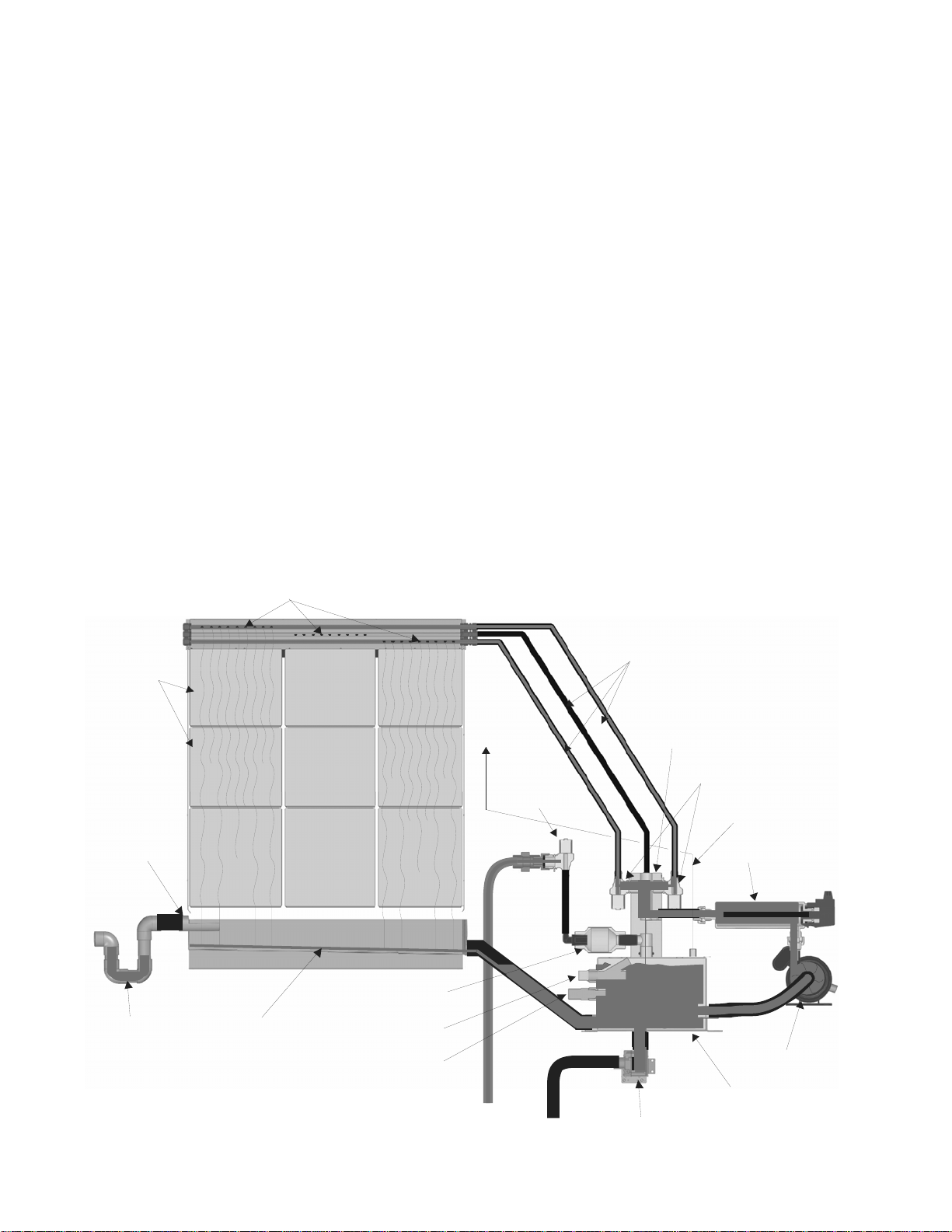
How the MH works
Media
Boxes
Overflow
Spray Bars
Stage 1 Stage 2 Stage 3
Check Valve
To duct
Fill Valve
Spray Bar Lines
Staging Manifold
Staging Valve s
Pressure
Equaliza t ion line
UV Light
P Trap
Drain Pan
1 | The Nortec MHTC / MHB
Float
Conductivity
Sensor
Drain
Figure 1: MHTC Reflow Schematic
Pump
Reservoir
Drain Valve
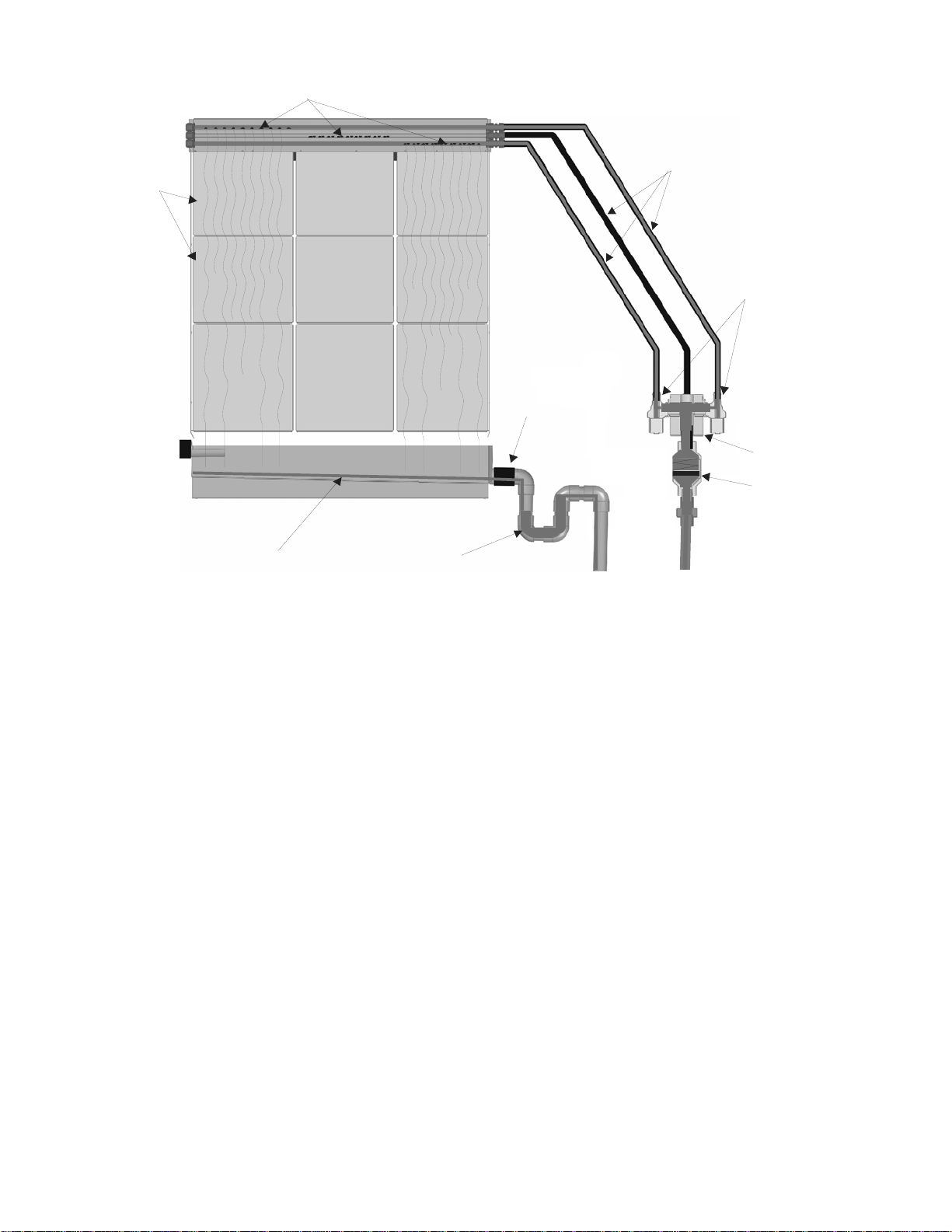
d
Spray Bars
Media
Boxes
Stage 1 Stage 2 Stage 3
Drain Pan
P Trap
Spray Bar Lines
Staging Valves
Drain
Staging Manifol
Check Valve
Figure 2: MHTC Flow / MHB Schematic
Humidification / Cooling
When a demand is received, the MH will;
MHTC Reflow - turn on its pump and UV light and after a short delay activate staging valves
as required to meet demand. Water will flow through the UV light, staging manifold, open
staging valves, and spray bar lines to the spray bars.
MHTC Flow / MHB – Activate staging valves as required to meet demand. Water will flow
through the staging manifold, open staging valves, and spray bar lines to the spray bars.
Each spray bar has a series of holes which allow water to flow out over a section of
evaporative media. As Water runs down the evaporative media some of it is evaporated by
air passing through the media. As a result of the evaporation the humidity of the air is
increased and the temperature of the air is decreased.
Any water that is not evaporated collects in the drain pan and;
MHTC Reflow - flows back to the hydraulic unit reservoir to be recirculated. As water is
evaporated the water level in the reservoir decreases and the float opens. The MH then
refills until the float is closed.
MHTC Flow / MHB – flows down to drain. The MHTC Flow / MHB does not have a reservoir
or pump and water simply flows through the staging valves when they are open using supply
water pressure to generate flow.
During operation the controller responds to changes in demand by opening and closing
staging valves. This allows the MH to match its output to demand.
The Nortec MHTC / MHB | 2

When demand is satisfied the MH will;
MHTC Reflow – turn off all staging valves and after a delay turn off the UV light and pump.
MHTC Flow / MHB – turn off all staging valves.
Water Management (MHTC Reflow only)
During the evaporation process minerals are left behind by the evaporated water resulting in
an increase in concentration in the remaining water. To prevent minerals from collecting in
and fouling the evaporative media more water is supplied to the media than can be
evaporated. The unevaporated water carries the minerals left by evaporated water to the
reservoir.
To prevent the mineral concentration from increasing to the point where excess water can
no longer dissolve minerals left in the media by evaporated water, the MH will periodically
flush the reservoir. The method used to determine when to flush the tank is configured
using display and keypad. Two triggers can be set.
Trigger 1
Time – The MHTC flushes the tank at a specific time every day.
Periodic – The MHTC flushes the tank after a fixed number of operating hours.
Demand - The MHTC flushes the tank after a fixed number of weighted hours ( weighted
hours = hours of operation x demand% )
Trigger 2
Cycle – The MHTC flushes the tank after a fixed number of fill cycles.
μSSensor (requires optional conductivity sensor)– Flushes the tank when the conductivity
sensor indicates the concentration of minerals exceeds a configured maximum value.
In general more frequent drains result in less maintenance. The amount of water drained to
control mineral concentration in the recirculating water can be configured in the MHTC’s
software.
Pressure Equalization Line (MHTC Reflow only)
In order to ensure that water flows properly from duct module’s drain pan to the MHTC Reflow’s
reservoir a pressure equalization line must be installed between the reservoir and the duct
down stream of the duct module. The line ensures pressure in the reservoir and duct are equal
and water flows properly from the drain pan to the reservoir.
UV Light
A UV light is standard on the MHTC Reflow and optional on the MHTC Flow / MHB. The UV light
prevents bacteria in the supply water or reservoir from being introduced into the evaporative
media. It does not kill bacterial that may be introduced into the media in the air stream.
Box Drying / Box Washing
In order to prevent bacteria from growing in the evaporative media the MH includes a box drying
cycle that allows the media to dry out. The MH will periodically close all staging valves and allow
the media to dry out regardless of demand.
In order to wash minerals from and prolong media life the MH includes a wash cycle which turns
on all staging valves regardless of demand or control status and rinses the media.
3 | The Nortec MHTC / MHB
MH Models
The MH2 is available in three models (see Figure 3: MH Models and Table Table 3: MH
Specifications).
MHTC Reflow - provides state of the art control technology with staged output to match
demand. The Reflow model also includes a hydraulic unit that provides maximum water
conservation by recirculating unevaporated water.
MHTC Flow - provides the same state of the art control technology including staging of
output to match demand but without the hydraulic unit for recirculating water.
MHB - provides basic operation without any user configurable features.
MHTC Reflow MHTC Flow MHB
OR
Single StageMult i S t age
Figure 3: MH Models
Each MH model is coupled with a duct module that contains the evaporative media used for
humidifying / cooling the duct air. The duct module is basically the same for each model with
the exception of the number of spray bars which are used for staging output.
The Nortec MHTC / MHB | 4
MHTC Reflow vs MHTC Flow and MHB
All units run a small excess of water over the media during operation to wash minerals away
and prolong media life. The MHTC Flow and MHB direct this water directly to drain, while the
MHTC REflow recaptures and reuses the water. The REflow is the most water efficient model
and recommended for good quality potable water and treated water types. Flow models are
recommended for areas with hard potable water, or where a central wastewater recovery
strategy is being used. See Table 1: MHTC Reflow / MHTC Flow / MHB Features for a listing of
the additional features provided by the MHTC Reflow.
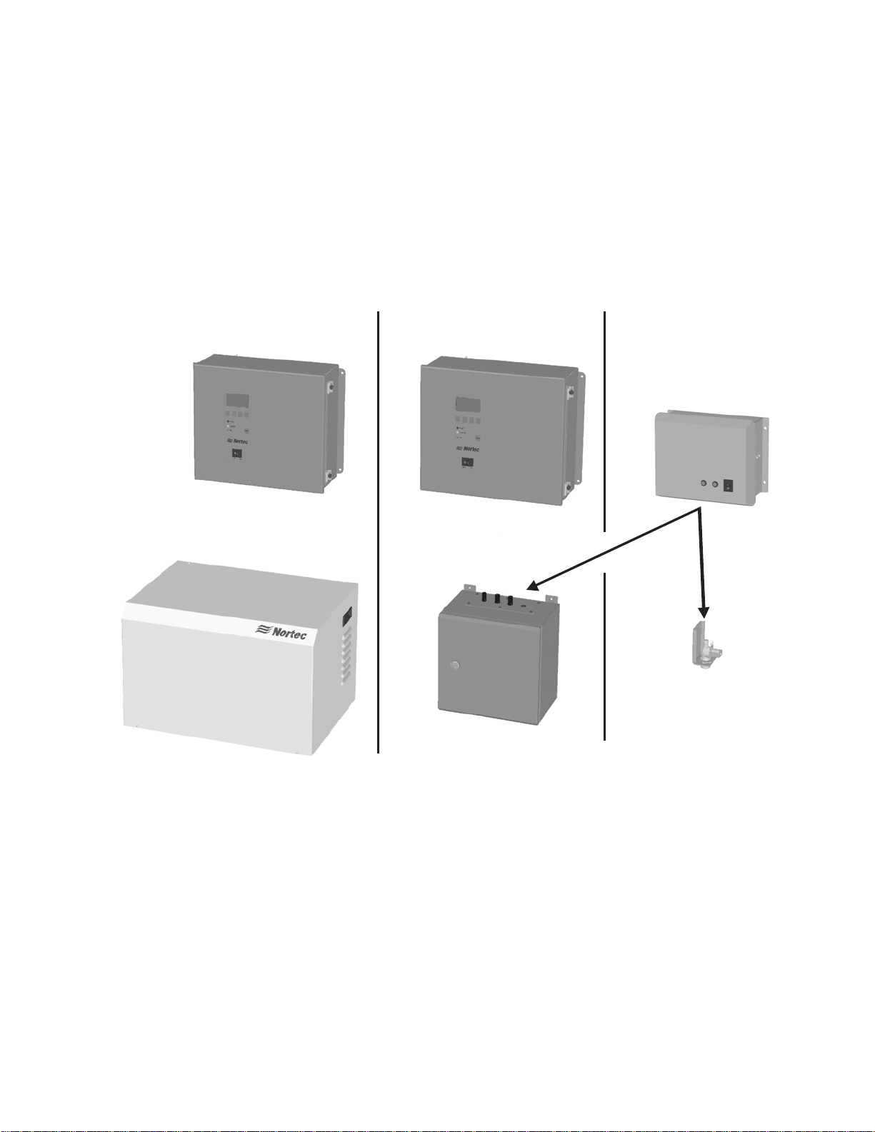
MHTC Flow vs MHB
The main difference between the MHTC Flow and the MHB model is in their controls and user
interface. The MHTC model’s Total Controller provides a graphic LCD screen and keypad,
accepts additional control signals and has optional building management system connectivity
(BACnet, Lonworks, Johnson N2, and Modbus). The MHB controls provide the basic
functionality required for operation. See Table 1: MHTC Reflow / MHTC Flow / MHB Features
for a listing of the two control systems features. Figure 4 shows the differences in the MHTC’s
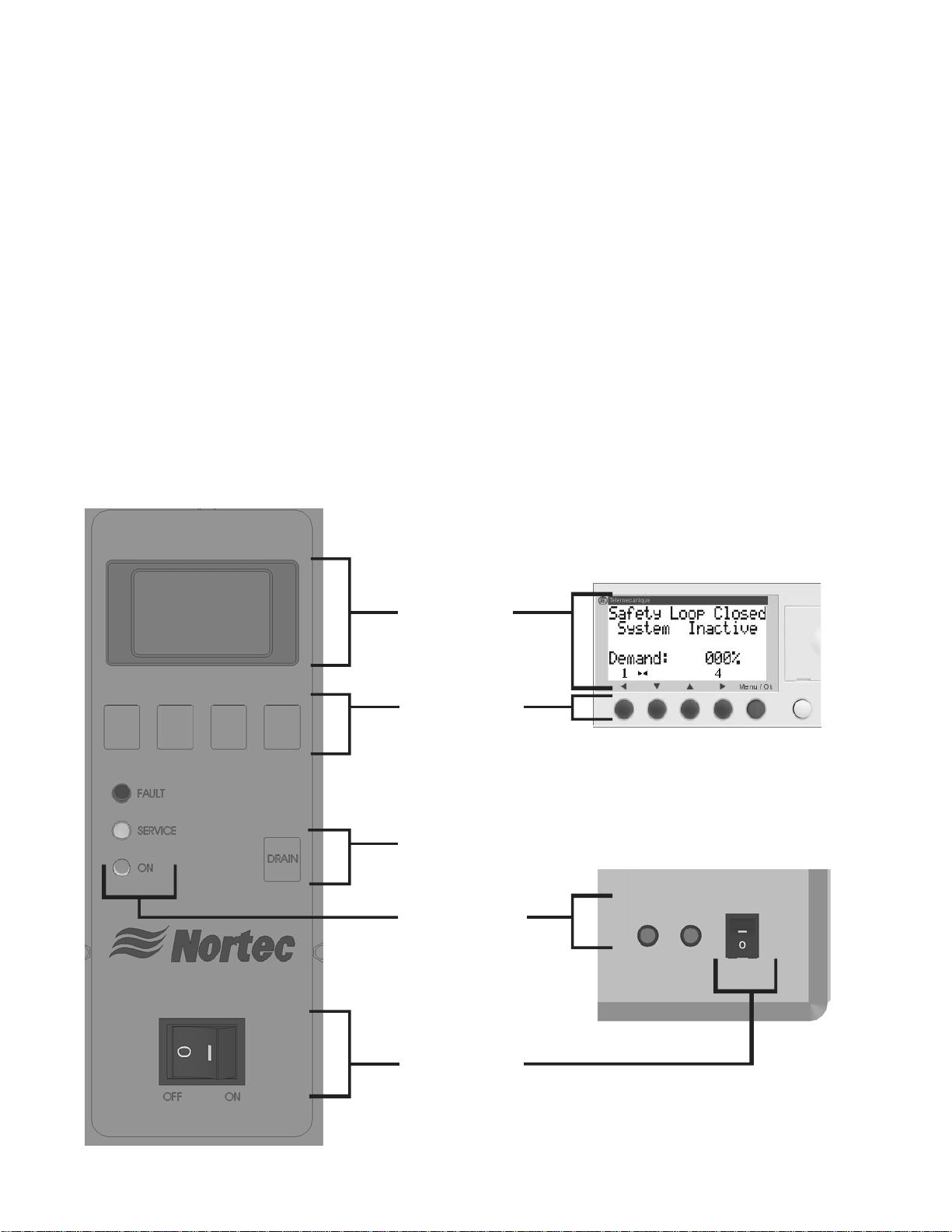
and MHB’s user interface.
MHTC
MHB
LCD Display
Inside Control Box
Input Buttons
(MHTC used to
navigate screens
and for configuration,
MHB for factory
configuration only.)
Sof tware Drain
Button
(Initiates a software
controlled drain)
Status LEDs
Lights
Outside Control Box
5 | The Nortec MHTC / MHB
On/Off Switch
(Turns humidifier
On/Off)
Figure 4: MHTC and MHB User Interfaces

The MHTC LCD screen and keypad - allow easy configuration of all features of the MHTC
humidifier such as control signals, box washing / drying, tank flushing, maintenance reminders,
and others. The LCD screen also provides status information indicating current status and
configuration, service and fault messages, and troubleshooting information. One of the key
features of the MHTC controller is tracking operation and providing information about service
requirements to make it easy to service and maintain the MHTC.
MH Humidifier Features
From their patented evaporative media and modular design to the MHTC’s advanced control
system with optional internet based monitoring capability to the MHTC Reflows advanced water
conservation technology all MH models include many advanced features that set them apart
from other evaporative humidifiers / air coolers. The following list outlines some of the MH
series key features.
Table 1: MHTC Reflow / MHTC Flow / MHB Features
General MHTC Reflow MHTC Flow MHB
Patented synthetic V-profile evaporative media
Stainless steel duct / media box frames, and drain pan
Operates on DI/RO, Potable, Softened Water
Optional low pressure drop mist eliminator
Recirculating water system
Direct water system
Wash cycles and box drying
Step-Control 1,2, or 3 stage
Ultra violet water treatment
Installation / Maintenance
All electrical components outside of duct
Modular easy to change media boxes
Programable maintenance settings
Wide range of water management options
Electronics
Graphic display screen with keypad input
LED status indicators
Remote status via dry points
Staged output based on modulating signal
Proportional and integral internal control from humidity
sensor inputs
Manual capacity adjustment
On/Off operation
Compatible with all standard Industrial controls
BMS (Lonworks, BACnet, Johnson, Modbus)
Other
UL900 Class 1 Flame and Smoke USA
ULC-S111-07 Class 2 Flame and Smoke Canada X X X
X X X
X X X
X X X
Optional Optional Optional
X
X X
Configurable Configurable Factory Set
X X X
X Option Option
X X X
X X X
X X
X
X X
X X (2 lights)
X X
1-3 Stages 1-3 Stages 1 stage
X X
X X
X X X
X X
Option Option
X X X
The Nortec MHTC / MHB | 6
V
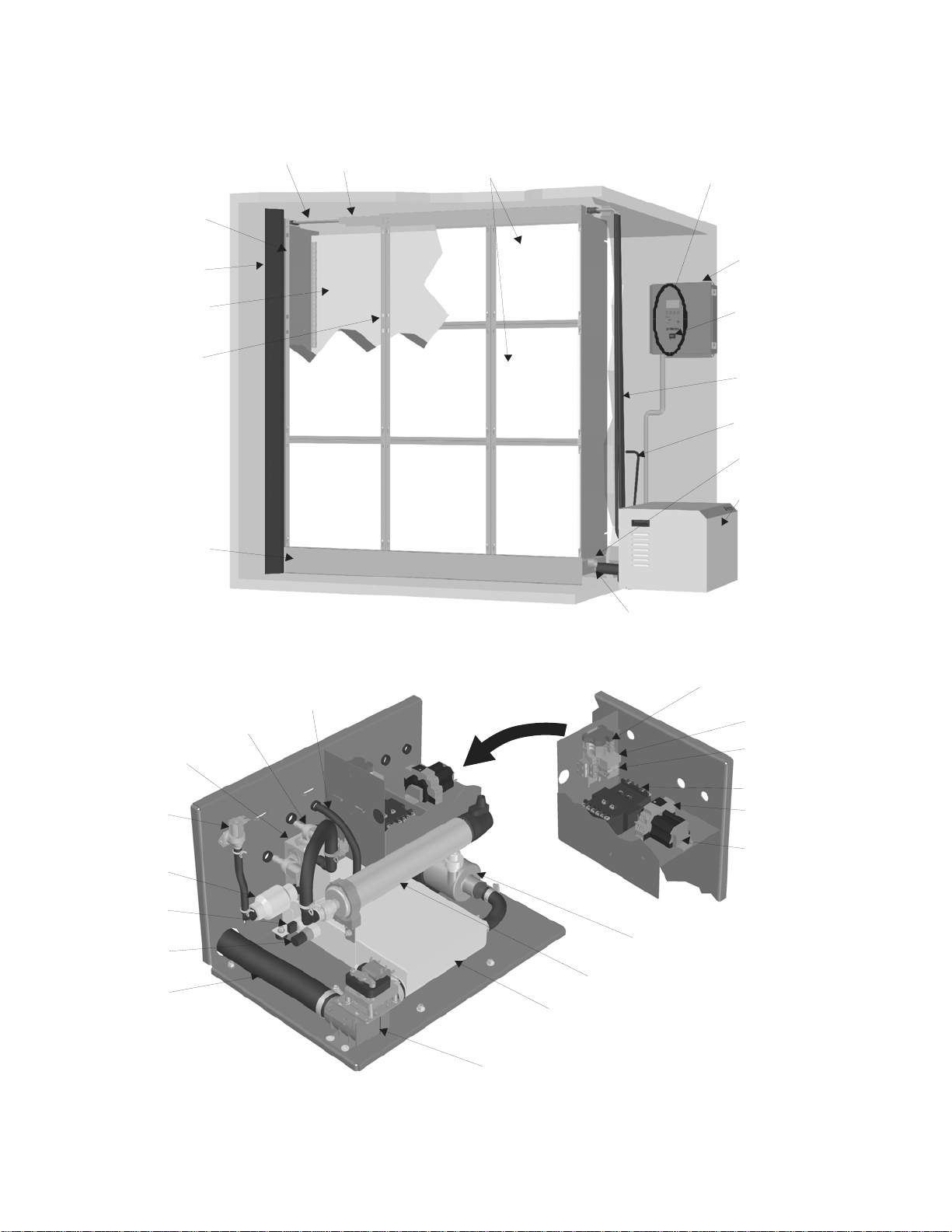
MH Components
Spray
Bars
Right
Side Panel
Duct Seal
Mist
Eliminator
Intermediate
Member
Drain
Pan
Equalization
Staging
Staging
Manifold
Fill
Valve
Check
Valve
Float
Conductivity
Sensor
Drain Outlet
Valve
7 | The Nortec MHTC / MHB
Pressure
Line
Spray Bar
Cap
Media Boxes
Reservoir
Drain Valve
Figure 5: MH Humidifier Components
Display and Keypad
Control
Box
On/Off Switch
Water Lines
Pressure
Equalization
Line
Drain
Overflow
Hydraulic
Unit
Drain Pan Drain
High Voltage
Terminal Block
Fuse Bloc k
Pump and U
Light Relay
Transformer
Conductivity
Transmitter
Low Voltage
Terminal
Block
(Hydraulic
Uni t )
Pump
UV Light

f
Description of Components
Table 2: Humidifier Components
Component Function of Component
Check Valve Provides back flow protection for supply water line.
Conductivity Sensor
/Transmitter
Control Box /
Display and Keypad
Drain Pan Collects unevaporated water from media for recirculation or draining.
Drain Pan Drain Drain pan connection to hydraulic unit reservoir.
Drain Outlet Drain connection from the hydraulic unit.
Drain Overflow Provides protection from overfilling the drain pan.
Drain Valve Drains water from the reservoir.
Duct Seal Prevents duct air flow from bypassing the humidifier.
Fill Valve Controls makeup water flow to humidifier based on float level.
Float Measures water level in reservoir to prevent over filling.
Fuse Block Overcurrent protection for pump and UV light.
High Voltage
Terminal Block
Hydraulic Unit Collects water from the drain pan and pumps, treats with UV light, and
Intermediate
Member
Low Voltage
Terminal Block
Media Boxes Surface from which water is evaporated for humidification/cooling.
Mist Eliminator Captures any water droplets that are carried off the media boxes with air
On/Off Switch Turns power On/Off to humidifier controller. Note: Turn off humidifier
Pressure
Equalization Line
Pump Pumps water from the reservoir to the media boxes.
Pump and UV Light
Relay
Reservoir Collects water from the drain pan for recirculation / draining.
Side Panel, Right Structural member supports media boxes and spray bar cap.
Spray Bar Cap/
Spray Bars
Staging Manifold /
Valve(s)
Transformer Steps primary voltage down to 24 VAC for the controller and internal
UV Light Eliminates any bacteria in the water being pumped to the media boxes.
Water Lines Supply water lines from hydraulic unit to spray bars.
Sensor measures conductivity of water in the reservoir. Transmitter
sends measured value to control box for use in water quality control.
Controls all functions of the humidifier’s operation and provides user
interface for configuration of the humidifier.
Primary voltage connection on hydraulic unit and in control box.
stages water to media. Fills and drains reservoir to control water quality.
Structural member supports media boxes.
Hydraulic Unit – connects control box inputs to the hydraulic unit.
Control Box – provides connection for control signals and safety loop.
Available in 8 in. (20 cm) or 12 in. (30 cm) thickness.
flow in high duct speed applications.
disconnect to shut off primary power to the humidifier.
Balances pressure in hydraulic unit reservoir with pressure in duct to
ensure proper water flow to reservoir from drain pan.
Turns on power to the UV light and pump based on signal from the
control box.
Distributes water to the media boxes and prevents water from spraying
anywhere else.
Controls flow o
water to media boxes based on demand.
components such as the fill valve and drain valve.
The Nortec MHTC / MHB | 8

t
t
MH Specifications and Dimensions
Table 3: MH Specifications
Voltage
Control signals
Max No. of Stages
Water supply
Water drain
Control accuracy
Supply water pressure
Supply water temperature
Water quality
Max. allowable air velocity through
media
Pressure drop
Ambient conditions (control unit)
Fire classification of evaporative media
MHB
120 VAC / 60 Hz 120 VAC / 60 Hz 120 VAC / 60 Hz
On/Off
Dry set of points
3 3 3
3/4 in. BPP, 1/2 in.
NPT adapter provided
2 in. (50.8 mm) OD
ube
Depends on air conditions, number of stages, and control setup
30-145 psi (2-10 Bar)
Tap water, reverse osmosis, softened or fully demineralized water.
1100 fpm (5.5 m/s) with mist eliminator.
Typically 0.44 IWC (250 Pa) @ 500 fpm (2.5 m/s) and 90% RH
34 –104 ºF (1- 40 ºC) Max 75% RH
UL900 Class 1 USA, ULC-S111-07 Class 2 Canada
MHTC
Flow
VDC 0-5, 1-5, 0-10,
2-10, 0-16, 3.2-16
mA 0-20, 4-20
1/2 in/ FPT 3/4 in. BPP, 1/2 in.
NPT adapter provided
2 in. (50.8 mm) OD
ube
41-113 ºF (5-45 ºC)
750 fpm (3.8 m/s)
MHTC
Reflow
VDC 0-5, 1-5, 0-10,
2-10, 0-16, 3.2-16
mA 0-20, 4-20
2 in (50.8 mm) ID
hose
4 x 5/16 in
(8 mm)
12.0 in.
30.5 cm
O
16.7 in.
42.5 cm
17.5 in.
44.4 cm
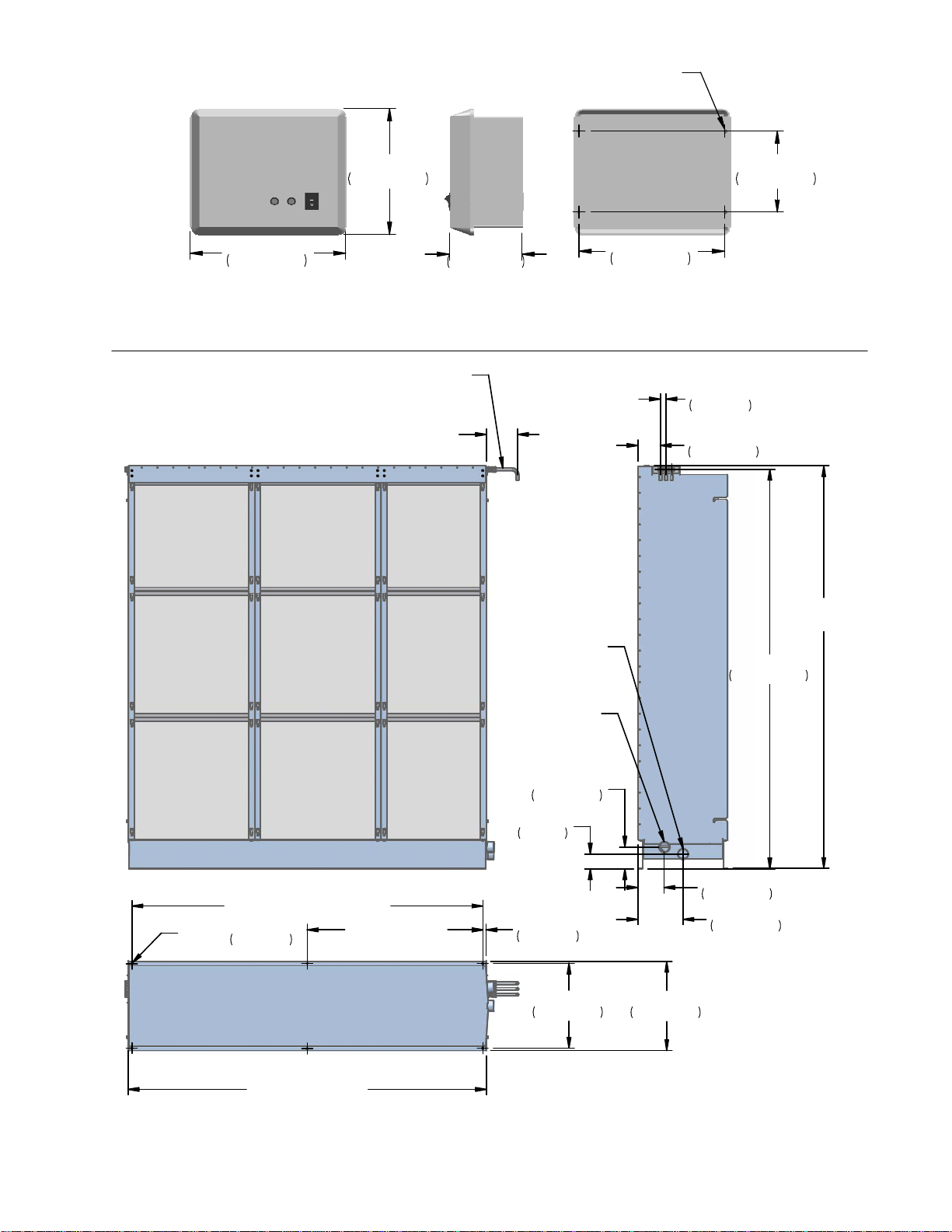
Figure 6: MHTC Reflow/Flow Control Box Dimensions
6.2 in.
15.6 cm
14.3 in.
36.3 cm
9 | The Nortec MHTC / MHB
4 x 0.31 in.
(8 mm)
O
9.3 in.
23.6 cm
11.5 in.
29.2 cm
5.4 in.
13.6 cm
6.0 in.
15.2 cm
10.75 in.
27.3 cm
Figure 7: MHB Control Box Dimensions
12 in. (30 cm) Supplied
Cut to Desired Length
1-3 x Spray Bar
1/2 in. (12.7 mm)
Tube
1.0 in.
2.7 cm
TYP
4.2 in.
10.7 cm
2.0 in (50.8 mm)
2 in. (50.8 mm)
Drain
Tube
Overflow
Tube
H=24 - 144 in.
(0.6 - 3.7 m)
74.6 in.
189.6 cm
W - 1.2 in (W - 3.2 cm)
O
0.2 in.
0.6 cm
6 X
W/2 - 0.6 in.
(W/2 - 1.6 cm)
4.1 in.
10.3 cm
2.8 in.
7 cm
0.6 in.
1.6 cm
4.9 in.
12.5 cm
8.4 in.
21.5 cm
15.8 in.
40.2 cm
16.6 in.
42.3 cm
W = 24 - 144 in.
(0.6 - 3.6 m)
Figure 8: MH Duct Module Dimensions
The Nortec MHTC / MHB | 10
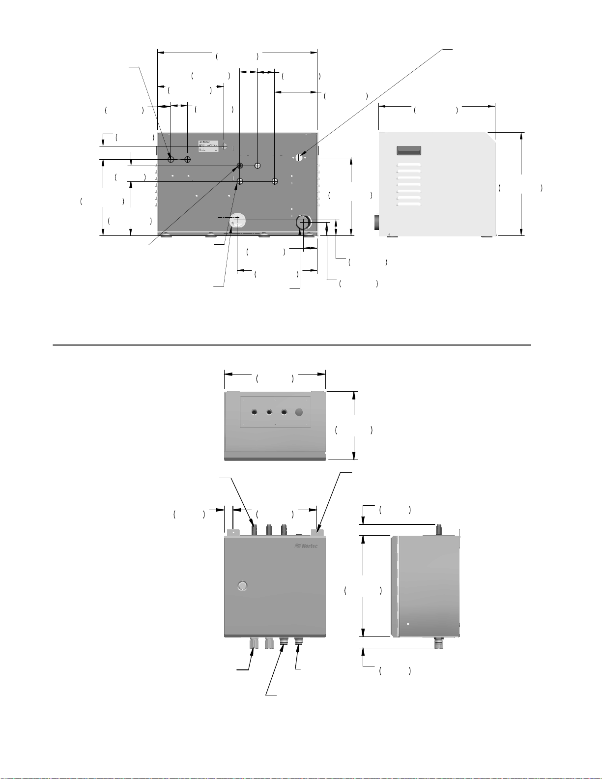
Electrical
3 x 7/8 in.
(22 mm)
11.5 in.
29.2 cm
Press. Equal.
1/2 in. (13 mm)
2.0 in.
5.2 cm
2.0 in.
5.1 cm
2.4 in.
6 cm
8.2 in.
20.8 cm
Hose Barb
2.6 in.
6.7 cm
10.0 in.
25.5 cm
2.5 in.
6.4 cm
Spray Bar
Connections
1-3 x 1/2 in.
(13 mm) Hose Barb
Drain Pan
Connection
2 in. Tube
24.1 in.
61.3 cm
2 in. ID Hose
2.1 in.
5.3 cm
12.1 in.
30.7 cm
Drain
2.6 in.
6.7 cm
6.4 in.
16.4 cm
11.8 in.
29.9 cm
2.4 in.
6.1 cm
2.0 in.
5.2 cm
Water Inlet
3/4 in BSP
(1/2 in. NPT
Adapter
provided)
17.6 in.
44.6 cm
15.6 in.
39.5 cm
Figure 9: MHTC Reflow Hydraulic Unit Dimensions
11.87
30.15
8.05
20.45
1 - 3 x 1/2 in. OD
Barbed Hose
1.00
2.55
9.87
25.07
2 x 1/4 in.
(6.4 mm)
O
1.31
3.33
11.88
30.16
2 x Water T ight
Electrical Connection
Figure 10: MHTC Flow/MHB Multi Stage Hydraulic Unit Dimensions
11 | The Nortec MHTC / MHB
Strain Relief
Drain
1/2 in. NPT
Water Inlet
1/2 in. NPT
1.32
3.36
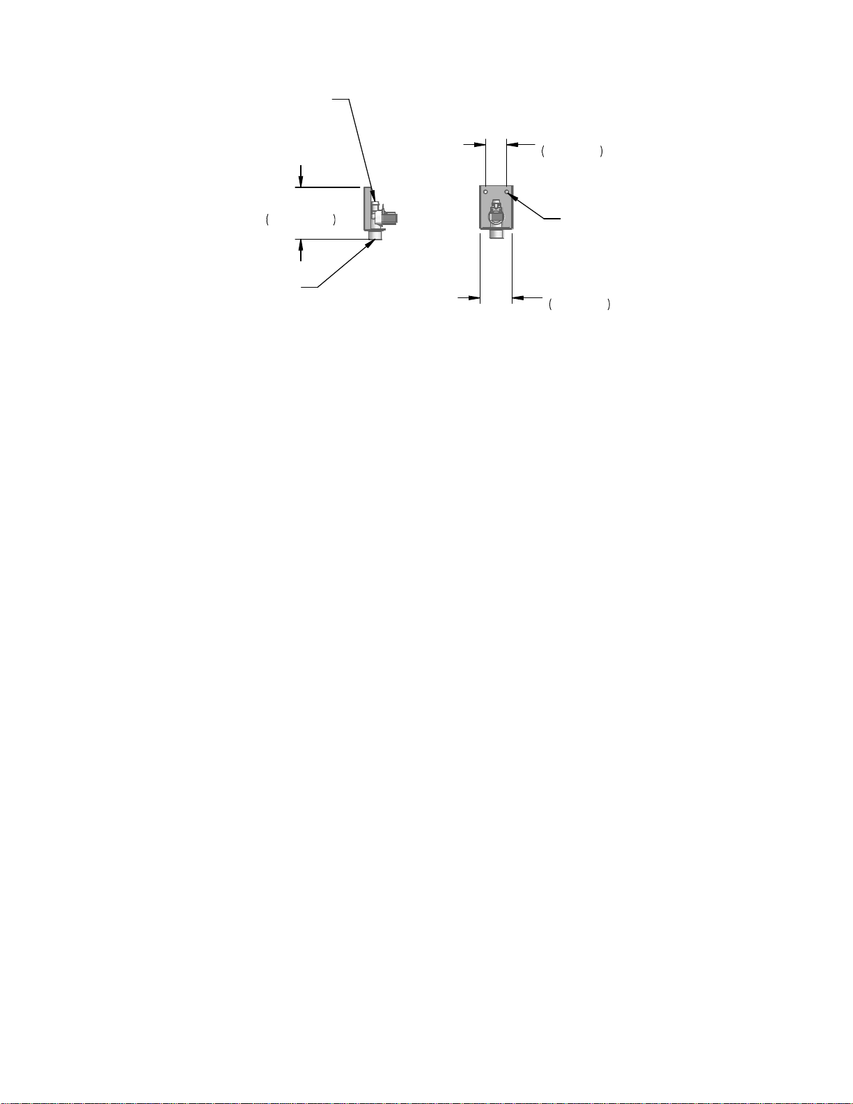
Spray Bar
Connection
1/2 in (13 mm)
Hose Barb
1.8 in.
4.4 cm
4.3 in.
10.9 cm
2 x 0.3 in.
(7.6 mm)
O
Water Inlet
3/4 in GHT
2.7 in.
6.8 cm
Figure 11: MHB Single Stage Hydraulic Unit
The Nortec MHTC / MHB | 12
 Loading...