

Page 1
Important: Read and save these instructions. This guide to be left with equipment.
MES2
Installation and
Operation Manual
Includes installation, operation
maintenance and troubleshooting
information for the MES2 Electrode
Steam humidifier
2554140-B|
24 OCT 2011
Page 2

Thank you for choosing Nortec.
INSTALLATION DATE (MM/DD/YYYY)
MODEL #
SERIAL #
CYLINDER #
Proprietary Notice
This document and the information disclosed herein are proprietary data of WALTER MEIER LTD. Neither this
document nor the information contained herein shall be reproduced, used, or disclosed to others without the
written authorization of WALTER MEIER LTD., except to the extent required for installation or maintenance of
recipient’s equipment. All references to the Nortec name should be taken as referring to WALTER MEIER LTD.
Liability Notice
Nortec does not accept any liability for installations of humidity equipment installed by unqualified personnel or
the use of parts/components/equipment that are not authorized or approved by Nortec.
Copyright Notice
Copyright 2011, WALTER MEIER LTD. All rights reserved.
Page 3

Contents
1 Introduction
2 Receiving and Unpacking
3 MES2 Models
6 Options and Accessories
7 Humidifier Components
9 Humidifier Schematic
9 How the Humidifier Works
11 Installation
12 Typical MES2 Installation
13 Location
14 Mounting
15 Plumbing
16 Steam Lines and Condensate
Returns
31 Maintenance and
Servicing
32 Required Maintenance
36 Extended Shutdown
37 Maintenance Checklist
39 Troubleshooting
41 General Troubleshooting
43 MES2 Faults
45 Wiring Diagram
46 Spare Parts
50 Warranty
19 Primary Voltage Wiring
20 Control Wiring
21 Modbus Wiring
22 MES2 Installation Checklist
23 Operation
24 User Interface
25 Humidifier Configuration
27 Modbus Configuration
30 Start Up Procedure
Page 4

Introduction
CAUTION: Servicing
Disconnect main power before performing any servicing.
The plumbing and electrical compartments contain high voltage components and
wiring. Access should be limited to authorized personnel only.
During and following operation of the humidifier, the steam and components in
contact with the steam such as the steam lines, steam distributors, cylinders, and
condensate lines can become hot and can burn if touched.
Walter Meier does not accept any liability for improperly installed humidity
equipment or the use of parts/components/equipment that are not authorized or
approved by Walter Meier.
CAUTION: Electrical
All electrical work should in accordance with the local electrical code in location
where the humidifier will finally be operated.
CAUTION: Plumbing
Drain water from humidifier can be very hot. Do not drain to public sink.
All plumbing work should be in accordance with local plumbing code in location
where the humidifier will finally be operated.
CAUTION: Installation
Do not mount on hot surfaces
Do not mount in area where freezing can occur
Do not mount on vibrating surface
The MES2 produces steam at atmospheric pressure. No devices which could block
steam output should be connected to the steam outlet.
Steam lines must be installed so that no restriction can produce backpressure in
the humidifier.
Regardless of selecting on/off or modulating control method, Nortec humidifiers
must have a closed circuit across its on/off security loop control terminal to
operate. Nortec highly recommends the use of a duct high limit humidistat and air
proving switch.
1 | Introduction
Page 5
Receiving and Unpacking
1 Check packing slip to ensure ALL material has been delivered.
2 All material shortages are to be reported to Nortec within 48 hours from receipt of goods.
Nortec assumes no responsibility for any material shortages beyond this period.
3 Inspect shipping boxes for damage and note damages on shipping waybill accordingly.
4 After unpacking, inspect equipment for damage and if damage is found, notify the shipper
promptly.
5 All Nortec products are shipped on an FOB factory basis. Any and all damage, breakage or
loss claims are to be made directly to the shipping company.
Before Installation
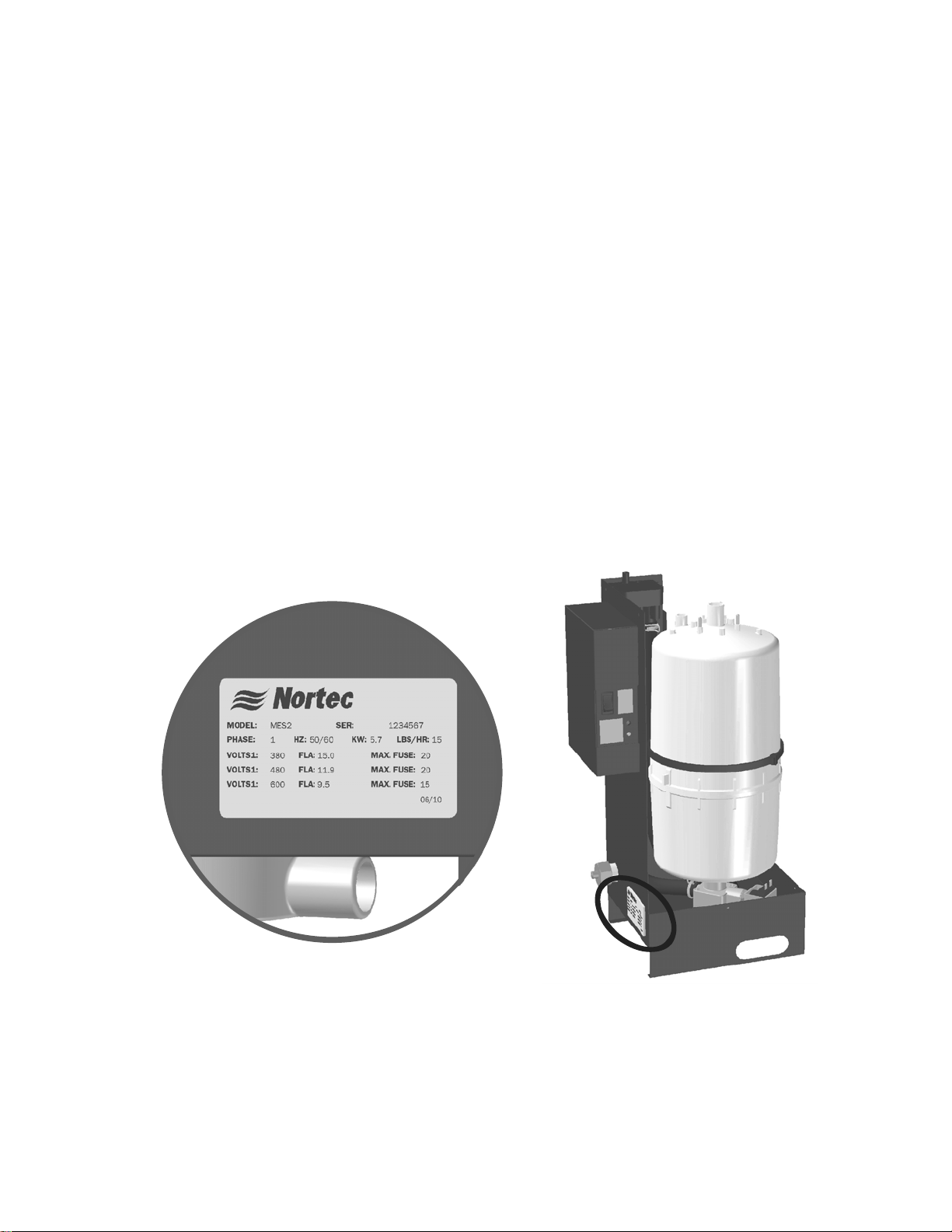
1 Ensure that available voltage and phase corresponds with humidifier voltage and phase as
indicated on humidifier’s specification label.
2 Ensure that the dedicated fused disconnect provided for the humidifier is of sufficient size to
handle the rated amps as indicated on the specification label.
3 Ensure sufficient clearances will be available as described in “Location” on page 13.
4 Ensure steam lines can be routed to distributor as described in Steam Lines and
Condensate Returns on page 16.
Figure 1: Specification Label Location
Introduction | 2
Page 6
MES2 Models
Open
Elect
ricalClosed
Elect
ric
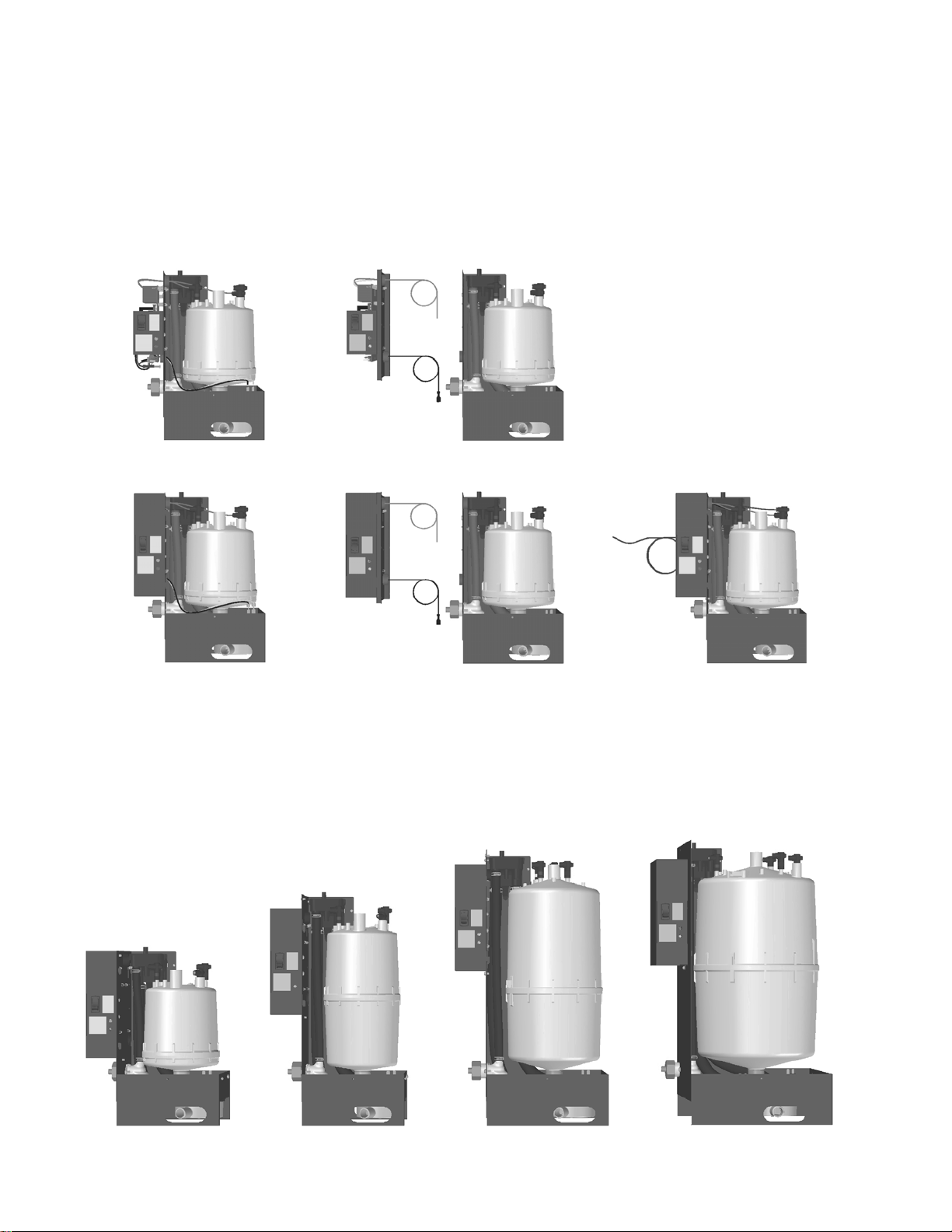
The MES2 is the most advanced OEM steam humidifier available and provides steady and
reliable humidification using the same proven cylinder technology as Nortec’s commercial
NHTC. The MES2 is offered in 5 models corresponding to control configurations as shown in
Figure 2. The remote configurations include 8 ft (2.4 m) of wiring for connecting the controls
to the plumbing cabinet. The Primary Voltage Wiring (PVW) model provides 8 feet of primary
wiring for connection to the contactor.
RemoteAttached Attached PVW
N/A
(ATT OE)
al
(ATT CE) (ATT CE PVW)
Figure 2: MES2 Models
The MES2 is available in 6 capacities ranging from 5 to 30 lb/hr (2.3 to 13.6 kg/hr) for
operation on a range of voltages and phases as outlined in Table 1: MES2 Part Numbers and
Electrical Data. The 6 capacities are packaged in 4 different cabinet sizes as shown in Figure 3.
5 lb/hr
(2.3 kg/hr)
10 lb/hr
(4.5 kg/hr)
(REM OE)
(REM CE)
15 - 20 lb/hr
(6.8 - 9 .1 kg/hr)
25 - 30 lb/hr
(11.4 - 13.6 kg/hr)
Figure 3: MES2 Capacities and Cabinets
3 | Introduction
Page 7
A
S
V
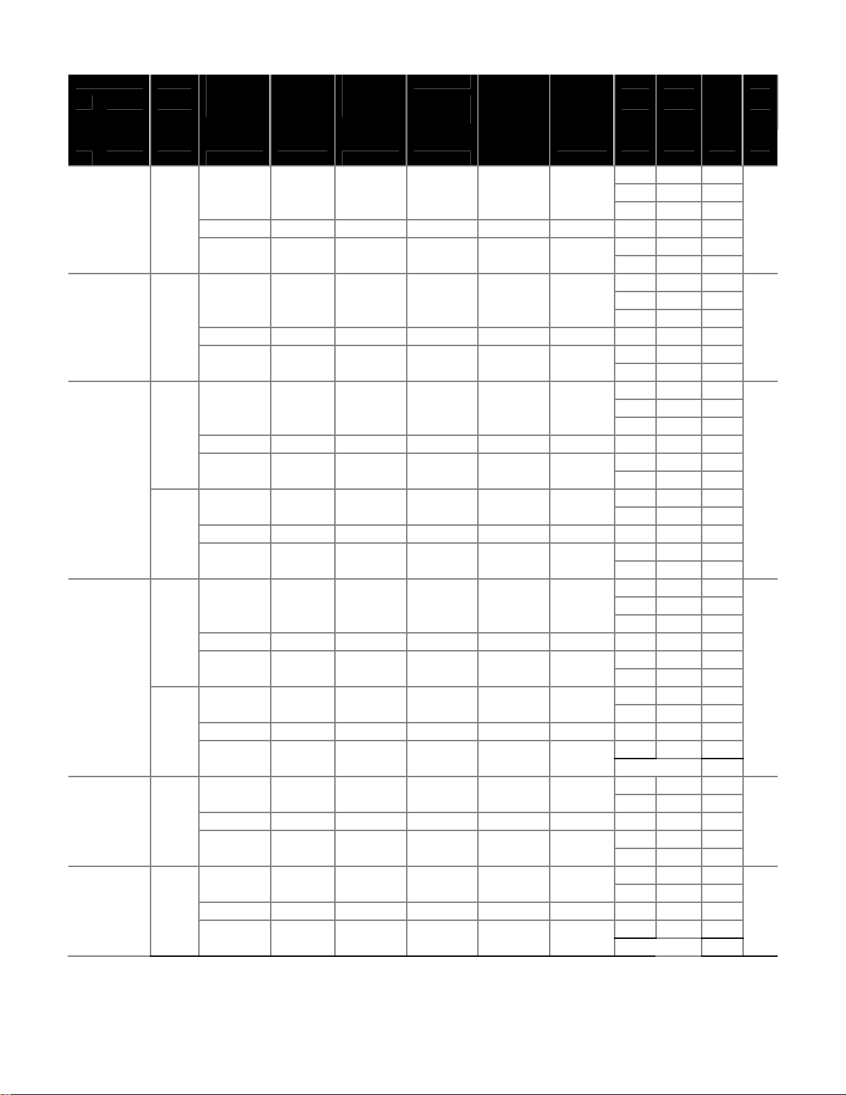
Table 1: MES2 Part Numbers and Electrical Data
Capacity Phase Attached
Closed
lb (kg) ATT OE ATT CE REM OE REM CE
Open
Elec.
5 (2.3) 1 2550262 3E+06 2550264 2550265 2550266 102 208 8.2 15 1.7
2550267 3E+06 2550269 2550270 2550271 103 380 4.5 15
2550272 3E+06 2550274 2550275 2550276 104 480 3.5 15
10 (4.5) 1 2550277 3E+06 2550279 2550280 2550281 202 208 16 25 3.4
2550282 3E+06 2550284 2550285 2550286 203 380 8.9 15
2550287 3E+06 2550289 2550290 2550291 204 480 7.1 15
15 (6.8) 1 2550300 3E+06 2550302 2550303 2550304 321 208 25 40 5.1
2550305 3E+06 2550307 2550308 2550309 305 380 13 20
2550310 3E+06 2550312 2550313 2550314 309 480 11 15
3 2550315 3E+06 2550317 2550318 2550319 303 208 14 20
2550320 3E+06 2550322 2550323 2550324 311 380 7.7 15
2550325 3E+06 2550327 2550328 2550329 311 480 6.1 15
20 (9.1) 1 2550340 3E+06 2550342 2550343 2550344 321 208 33 50 6.8
2550345 3E+06 2550347 2550348 2550349 305 380 18 30
2550350 3E+06 2550352 2550353 2550354 309 480 14 25
3 2550355 3E+06 2550357 2550358 2550359 303 208 19 30
2550360 3E+06 2550362 2550363 2550364 311 380 10 15
2550365 3E+06 2550367 2550368 2550369 311 480 8.2 15
25 (11.4) 3 2553765 3E+06 2553767 2553768 2553769 421 208 24 35 8.5
2553770 3E+06 2553772 2553773 2553774 407 380 13 20
2553775 3E+06 2553777 2553778 2553779 411 480 10 15
30 (13.6) 3 2550370 3E+06 2550372 2550373 2550374 421 208 28 40 10
2550375 3E+06 2550377 2550378 2550379 407 380 16 25
2550380 3E+06 2550382 2550383 2550384 411 480 12 20
Attached
Closed
Elec.
Remote
Open
Elec.
Remote
Elec.
ttached
Closed
Elec. PVW
ATT CE
PVW No. V A A KW
tandard
Cylinder
olts Amps Max
Ext
Fuse
240 7.1 15
277 6.1 15
600 2.8 15
240 14 20
277 12 20
600 5.7 15
240 21 30
277 18 30
600 8.5 15
240 12 20
600 4.9 15
240 28 45
277 25 35
600 11 20
240 16 25
600 6.5 15
240 20 30
600 8.2 15
240 25 40
600 9.8 15
KW
Introduction | 4
Page 8

MES2 Dimensions / Weights
0.34 (9 mm)
Condensate
0.57
1. 4
C
Re t ur n
0.30
0.8
1/ 8 NPT
Fill Connection
2.30
5.8
F
5.50
14
1. 2 8
3.3
7.79
19 .8
G
D
A
E
B
0.875 (22 mm)
St e am Out l et
0.80
2
O
3.70
9.4
1. 7 3
4.4
1.12 x 2.0 (2.85 x 5.1) Slot
Both Cabinet Sides
H
0.875 (22 mm)
O
Drain Outlet
5.45
O
13 .8
Rotate 360
v
to
Desired Position
Note: Unless otherwise specified dimensions are in inches (cm). Tolerance ±0.1 in. (0.25 cm)
Capacity
lb/hr (kg/hr) A Width B Depth C Height
5
(2.3)
10
(4.5)
15-20
(6.8 – 9.1)
25-30
(11.4 – 13.6)
Note: * Steam Outlet is not centered on MES2 5 & 10 lb/hr (2.3 & 4.5 kg/hr) models.
** Weights given for MES2 with enclosed electronics and optional plumbing enclosure. Full Weight is weight with cylinder full of
water. Full weight may exceed this value at end of cylinder life depending on the amount of scale and its composition.
7.5
(19)
7.5
(19)
8.9
(22.6)
10.3
(26.2)
6.4
(16.3)
6.4
(16.3)
7.9
(20.1)
9.8
(24.9)
12.7
(35.3)
16.8
(42.7)
20.0
(50.8)
20.7
(52.6)
D*
Steam
Outlet
4.2
(10.7)
4.2
(10.7)
5.1
(13)
5.5
(14)
E*
Steam
Outlet
5.1
(13)
5.1
(13)
4.0
(10.2)
4.9
(12.5)
F
Elec.
Pos.
0.3
(0.8)
0.3
(0.8)
1.1
(2.8)
2.2
(5.6)
G
Elec.
Height
4.9
(12.5)
8.0
(20)
11.2
(28.5)
11.6
(29.5)
2.5 (6.4) MES2 25 - 30
1.5 (3.8) MES 5 - 20
J
H
Drain
Center
5.6
(14.2)
5.6
(14.2)
6.4
(16.3)
6.8
(17.3)
J
Drain
Center
3.4
(8.6)
3.4
(8.6)
4.2
(10.7)
5.2
(13.2)
Net/Full
Weight**
lb (kg)
10.7/14.2
(5/6.6)
12.4/18.4
(5.8/8.5)
16.5/30.5
(7.8/14.2)
20.2/43.2
(9.5/20.0)
Figure 4: MES2 Dimensions and Weights
5 | Introduction
Page 9
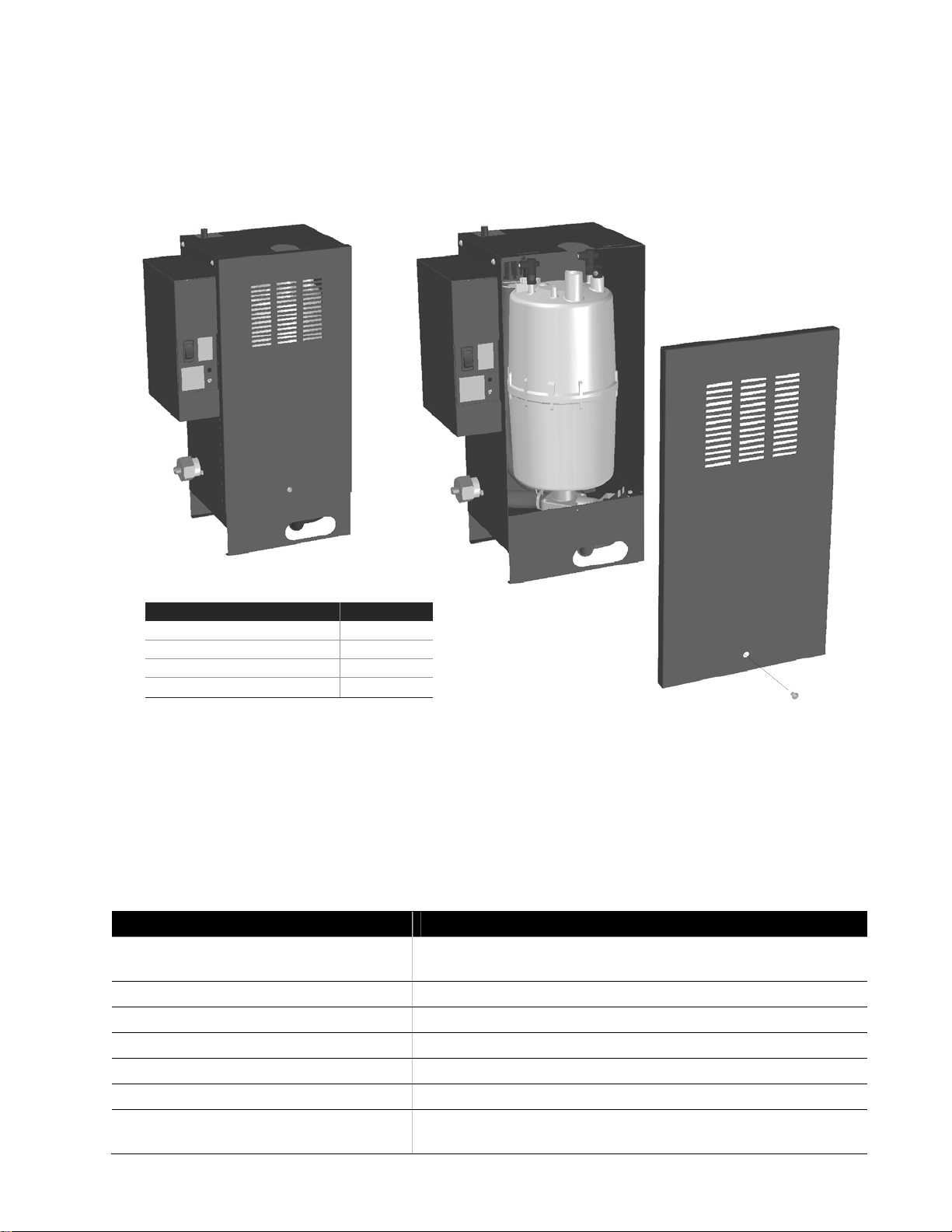
Options and Accessories
An enclosed plumbing option is available for each MES2 cabinet size. The option consists of a
fixed cabinet with an easily removable door for servicing. Figure 5 shows the enclosed
plumbing option installed on a 10 lb/hr MES2 ATT CE.
Enc losed P lumbing Part N umber s
Capacity Part No.
5 lb/hr (2.3 kg/hr)
10 lb/hr (4.5 kg/h r)
15, 20 lb/hr (6.8, 9.1 kg/hr)
25, 30 lb/hr (11.4, 13.6 kg/hr)
2554073
2554074
2554075
2554076
Figure 5: Enclosed Plumbing Option
Nortec also provides a complete line of options and accessories for every humidification
application. The following table lists some of the most common accessories available for use
with the MES2 humidifier. Refer to the installation instructions that come with the accessories
for their proper installation and operation.
Table 2: Options and Accessories
Option / Accessory Used For
Modbus Interface Controlling humidifier operation via Modbus (See Modbus Wiring
on page 21 and Modbus Configuration on page 27).
Enclosed Plumbing See above.
Steam Distributors Adding steam into air ducts.
On/Off or Modulating Control Humidistats Controlling the output of the humidifier based on sensed RH.
Air Proving Switch Insuring humidification only occurs when air is moving in a duct.
Steam Hose Connecting humidifier to steam distributor.
Condensate Hose Collecting and draining condensate that collects in steam
distributors and steam distribution lines.
Introduction | 6
Page 10
p
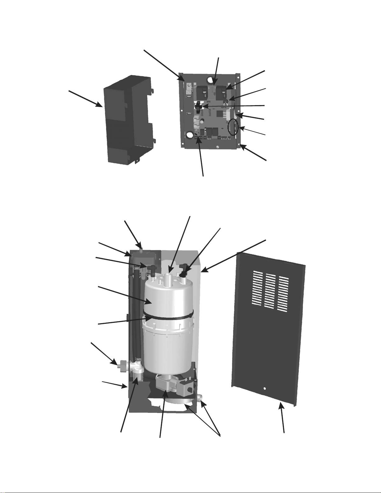
Humidifier Components
Ground Clam
Control Board
Power Relay
Electrical Cover
Fill Cup
Cyl i nder Plug
Condensate Return
Capaci ty A djustment
Potentiometer
Current Sensor
On/Off/Drain Switch
Status Lights
Bracket, Remote
El ectrical
Control Connection
Terminals
Steam Outl et
High Water Sensor
Plug
Pl umbing
Enc losure
(Optional)
Cyl i nder
Cyli nder
Tie Wrap
Fill Inlet
Drain Pan
Fill Valve
Drai n Valve
Drain Outlet
Drain Canal
Figure 6: MES2 Components
Pl umbing
Door
(Optional)
7 | Introduction
Page 11

Table 3: MES2 Components
Component Function of Component
Bracket, Remote
Electrical
Capacity Adjustment
Potentiometer
Condensate Return
Control Connection
Terminals
Current Sensor
Cylinder
Cylinder Plug
Cylinder Tie Wrap
Drain Outlet / Canal
Drain Pan
Supports the control components for MES2 models which have remote
electronics (REM).
Adjusts the maximum output of the humidifier from 100% down to 20%.
See Figure 22: Capacity Potentiometer Adjustment on page 26.
Provides a connection to return condensate to humidifier.
Terminals on the control board for connecting external controls to
humidifier.
Measures the amount of current flowing through the cylinder’s
electrodes.
Holds electrodes in water. Current between electrodes generates heat
used to generate steam.
Power connectors to electrodes in cylinder. Installer must connect wires
from contactor to cylinder plugs. (PVW model has wires installed).
Holds cylinder in place, reusable.
Combines cylinder drain water and fill cup overflow into a single drain
outlet.
Collects any water which may leak from water connections and routes it
to drain.
Drain Valve
Control Board
Electrical Cover
Fill Cup
Fill Inlet
Fill Valve
Ground Clamp
High Water sensor
Plug
On/Off/Drain Switch
Plumbing
Enclosure/ Door
Power Relay
Drains water from humidifier.
Controls all functions of the humidifier’s operation and provides input
and output connections to humidifier components.
Covers the control board and wiring on MES2 models with closed
electrical (CE).
Provides an air gap for backflow prevention.
1/8 NPT brass fitting for connecting supply water to the humidifier.
Controls flow of water into humidifier.
Electrical ground connection for humidifier.
Used to detect max water level in cylinder.
Turns power on/off to humidifier controller and drains the cylinder for
servicing. Note: Turn off humidifier disconnect to shut off primary power
to the humidifier.
The optional plumbing enclosure completely encloses the humidifiers
water components.
Turns on/off power to the contactor (supplied by others) based on a
signal from the humidifier’s controller (mounted on control board).
Status Lights
Steam Outlet
Indicate if the humidifier is operating. If the humidifier is shut down on a
fault the yellow LED flashes in sequence to indicate the fault that
occurred.
Outlet for steam generated by the humidifier. Connect to the outlet with
a steam hose and hose clamp.
Introduction | 8
Page 12
r
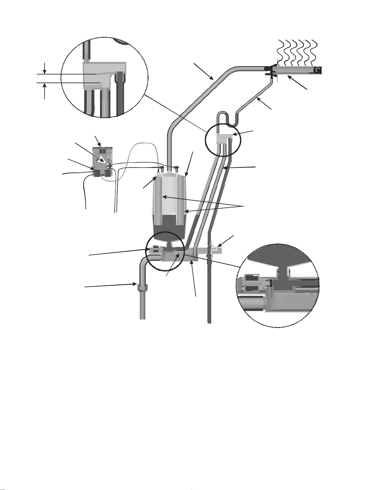
Humidifier Schematic
Air Gap
1.25 in.
(3.2 cm)
Steam Line
Steam Distributo
Condensate Return
Current Sensor
Power Relay
24 VAC
Drain Valve
External Air
Gap
Control Board
To
Contactor
Fill Cup
Cylinder
Overflow
High
Water
Sensor
Electrodes
From
Contactor
Fill Valve
Internal Air
Gap
Drain Canal
Figure 7: Humidifier Schematic
How the Humidifier Works
The MES2 is an atmospheric steam generator that uses heat generated by electrical current
flowing between submerged electrodes to generate steam. The MES2 is designed for air
humidification via steam distributor.
Steam Generation
If the MES2 is configured for On/Off operation then as soon as the safety loop between
terminal 1 and 2 is closed the humidifier assumes 100% demand, closes the power relay on
the control board, and measures the current flowing through the power wire routed through
the control board’s current sensor. If it is configured for modulating operation it waits for a
demand signal and for the safety loop between terminal 1 and 2 to be closed.
9 | Introduction
Page 13

If the demand is lower than the actual output the inlet valve is kept closed and output is
reduced by letting the water level in the cylinder decrease by evaporation.
If demand is higher than the actual output after a brief delay the fill valve is activated and
water flows into the fill cup. Water from the fill cup flows into the bottom of the cylinder
through a hose connected to the drain valve housing.
Note: The cylinder is gravity fed from the fill cup. If backpressure from the steam line is too
high it will cause water to back up in the fill cup and flow down the overflow line to the
drain.
A soon as the water in the cylinder comes in contact with the energized electrodes current
flows through the water. The resistance of the water to the electrical current generates heat
and in turn steam. The more electrode that is covered by water the higher is the current and
output. The unit continues to fill until the current matches demand or the high water sensor
detects a high water level.
The MES2 repeats the fill and boil down cycle repeatedly to match output to demand.
Over time minerals in the water will adhere to the cylinder’s electrodes. The humidifier will
automatically fill to a higher water level to maintain full capacity during the life of the
cylinder. Eventually because of scale formation it will no longer be possible for the
humidifier to reach its full capacity. The MES2 software monitors this condition and when
detected will stop operating and flash the yellow LED in a repeating sequence of 4 flashes.
Drains
As steam is produced minerals are left behind increasing the conductivity of the water. The
MES2’s patented auto adaptive cycle will monitor the water conductivity and perform drains
to maintain the water at optimal conductivity for peak performance.
The auto adaptive cycle provides the longest cylinder life in combination with keeping the
tightest control and most efficient use of water during the entire cylinder life.
Steam Distribution
The most common method for adding the steam into the air is to mount a steam distributor in a
supply air duct as shown in Figure 7: Humidifier Schematic. In an air handler the best location
for introducing the steam is after the heating coil where the air will be at its lowest humidity.
Steam Line
The steam line between the cylinder steam outlet and the distributor may be Nortec steam
hose, copper pipe, or stainless steel pipe or tube. The MES2 is an atmospheric steam
generator so it is very important no restrictions are present in the steam line and that the steam
line is sized properly to carry the full output capacity of the humidifier. See Steam Lines and
Condensate Returns on page 16 for information on selecting steam lines.
Condensate Return
Whenever steam is generated, condensate is formed in the distribution system and steam
distributor. Insulating steam lines is one important way to reduce the amount of condensate
formed. Steam lines are sloped so that condensate does not collect in the lines and create a
restriction to steam flow. The condensate must be collected and removed from the system so
that it does not build up and leak into the duct or air handler. Condensate can be returned to
the MES2 fill cup to reduce water waste or can be fed to drain.
Introduction | 10
Page 14

Installation
12 Typical MES2 Installation
13 Location
14 Mounting
15 Plumbing
16 Steam Lines and Condensate Returns
19 Primary Voltage Wiring
20 Control Wiring
21 Modbus Wiring
22 MES2 Installation Checklist
11 | Installation
Page 15
/Of
f
f
y
A
f
A
C o n t
t o
r
r
L1
r
r
r
r
A
r
Typical MES2 Installation
Control
Wiring
Pg 20
Steam
Distribution
Page 16-18
12 in. (30 cm)
min. radius*
1 ft (30 cm)
min. before
any bend*
2 in. (5 cm)
min.
1 ft (30 cm)
Support
brackets*
Condensate
trap
E
n
e
a
g
i
c
z
e
Steam Line
O
(
2
L
S
4
n
o
a
V
o
e
p
C
t
)
Front side
clearance required
for cylinder removal.
Power Relay
On/Of
Drain
Switch
Fuse
2
4
V
C
Location
Mounting
Pg 13
Fill
Line
36 in. (90 cm)
recommended
Drain
Line
Plumbing
Primary
Voltage
Pg 15
Pg 19
1/8 in.
NPT
Cold Potable Water
30 - 80 PSIG
0.875 in.
(22 mm).
OD
ir gap
recommended
Drain
7/8 in. Min.
Note:
Single Phase
Connection Shown
L2
Disconnect Contacto
Current transforme
* Dimensions and brackets are recommendations based on best practice. OEM must verify operation if they are not followed or used.
Cylinde
plug with
white
marke
Figure 8: Typical Humidifier Installation
Installation | 12
Page 16
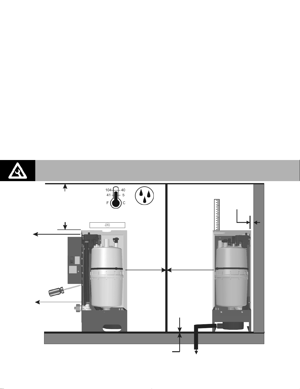
Location
Mount to structural member or on surface capable of supporting the humidifier’s operating
weight (see Figure 4: MES2 Dimensions and Weights). The humidifier may be set on its base but
clearance must be provided for the drain line to be sloped adequately. In general clearance is
not required around the humidifier except for maintenance access and electrical and plumbing
connections.
The clearance dimensions shown are recommendations based on best practice. OEM must
verify operation if they are not followed.
Install only in areas with ambient temperature 41-104°F (5–40°C) relative humidity 5 -
95%.
When possible install below the steam distributor. If mounted above the steam distributor
take care to provide proper steam line routing and proper condensate traps.
DO NOT locate the humidifier any further then absolutely necessary from the steam
distributor location as net output will be reduced as a result of heat loss through the steam
line.
The main service access required is for changing the cylinder. This access can be from the
front or right side. Right side service access is not possible with the optional plumbing
enclosure.
Note: Nortec recommends a vertical drop from the drain outlet and an air gap as close
as possible to the drain outlet to insure proper draining of the humidifier.
8 in. (20 cm)*
left side clearance
for remova l of cover
on attached closed
electronics models
0.5 in. (1.3 cm)*
top clearance
access hole required
for steam outlet and
optional condensate
return to fill cup.
only.
0 in . (0 cm)
access ho le or
additional clearance
required for fill
connection
Mount level
5-95%
in. ( cm)
00
side clearance
for front cylinder
cylinder removal
remo val
36 in. (92 cm)*
side clearance
for right side
only.
Note:
side cylinder
removal not
possib le with
enclosed
pluming option.
As close as
possible to steam
distributor
in. (92 cm)
36 *
front clearance
for front cylinder
remo val and/or fo r
attached electronics
models only.
0 in. (0 cm)
front clearance
for right side
cylinder removal
0.2 (0.5 cm)*
for fill cu p
tabs.
* Dimensions are recommendations based on best practice. OEM must verify operation if they are not followed.
13 | Installation
Access for properly sloped drain required.
0 in (0 cm) bottom clearance.
Figure 9: Mounting Location / Clearance
Page 17
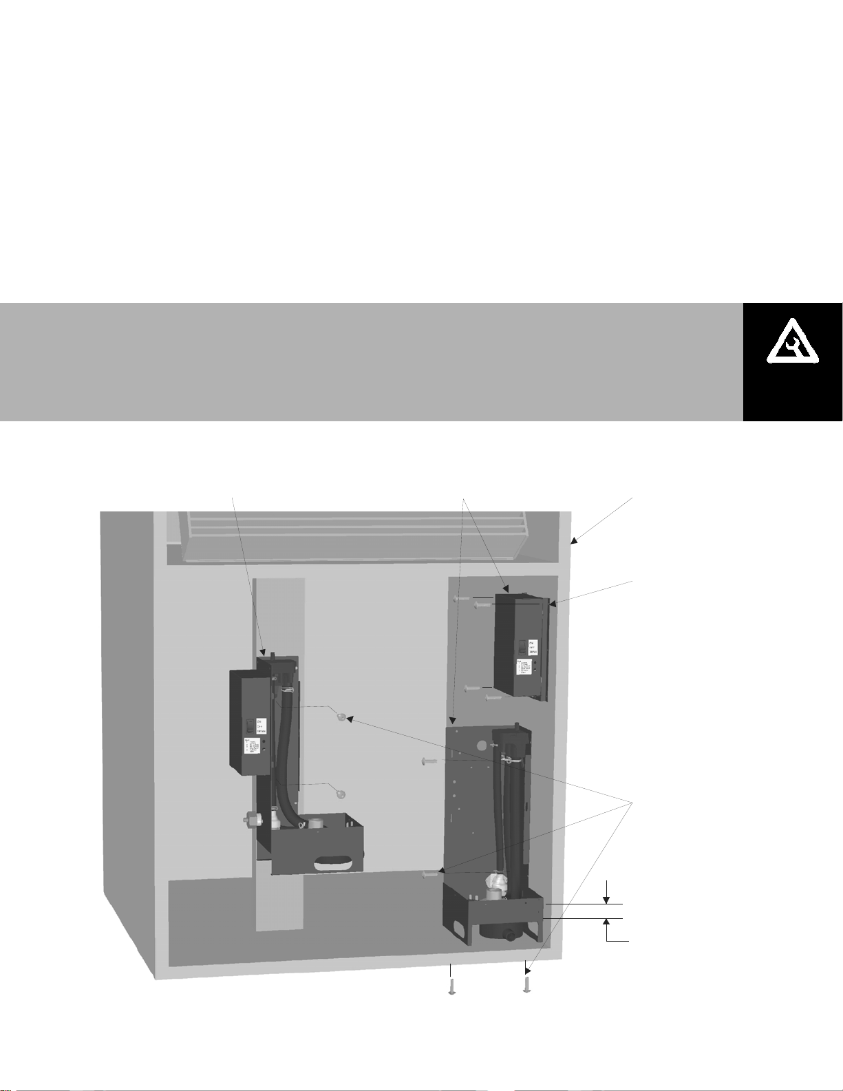
Mounting
1 The MES2 humidifier can be wall or floor mounted. No mounting holes are provided but can
be made anywhere in the base and sides of the cabinet at installation time.
2 Use a minimum of 2 x #8 screws mounted securely into structural surfaces.
3 Make sure the unit is level.
4 If enclosed plumbing option is installed then mounting screws can also be installed into the
plumbing enclosure.
5 It is the installer’s responsibility to insure that the humidifier is securely and safely mounted
in the air handler.
Note:
Installation methods shown are suggestions only actual mounting may differ and must
be verified by OEM.
When mounting to a vertical member by drilling holes in the cabinet, be careful not to
make any holes in the bottom 1 in (2.5 cm) of the drain pan.
MES2 Attached
Electronics
(Back Mounted)
MES2 Remote
Electronics
(Side/Base Mounted)
Air Handler
Remo te El ectr o n i cs
Mount using 4 s crews i
0.19 in. mounting holes
Plumbing
Drill holes in back ,
side, or base of c abinet
and sec ure with m in. of
2 x #8 Sc rews.
Figure 10: MES2 Mounting
Avoid drilling in
bottom 1 in (2.5 c m)
of drain pan.
Installation | 14
Page 18

A
r
f
r
Plumbing
1/8 in. NPT
fill connection.
0.875 in. (22 mm). OD
un-threaded outlet
Always install a water
All water supply and drain line connections should be installed in accordance with local
Supply water is recommended at 30 to 80 PSIG and 150-1200 Microsiemens (Hardness 0-
shut-off valve.
Use 1/2 in. OD coppe
to within 4 ft (1.2 m) o
humidifie
*Elbows, pipe, water shut-off valve, and air gap reducer not supplied by Nortec.
Figure 11: Water Supply and Drain Connection
plumbing codes.
12 GPG). Consult factory for water conditions outside of this range. Install water shut off
valve before humidifier to facilitate servicing.
Min. 7/8 in. OD drain line.
Ensure adequate slope to
handle flow.
ir gap recommended.
1 1/2 in. to 7/8 in.
Copper reducer is ideal.
(Nortec option P/N 2522172)
Hose must not touch the bottom
of the funnel.
The drain line should not end in a sink used frequently by personnel, or where plumbing
codes prohibit it. Route to a floor drain or equivalent for safety reasons.
Ensure drain line is adequately sized to provide free and easy draining and that an air gap is
installed as shown. A restricted drain can cause cylinder water to over concentrate and
result in poor operation.
If a drain is not located near the humidifier use a condensate pump rated for hot drain water
such as Nortec’s P/N 1429527.
15 | Installation
For humidifiers installed in some cities including the City of Los Angeles:
A city-approved spring-loaded double ball CHECK VALVE must be installed by
contractor on the potable water inlet to the humidifier. Recommended valve
manufacturer: Watts Regulator, Size 3/8” inlet and outlet, Model #7.
Each drain line from the humidifier must be routed, without dips or sags, to
terminate above the flood level rim of a city approved indirect waste receptor.
Page 19

Steam Lines and Condensate Returns
MAIN RULES FOR ATMOSPHERIC STEAM LINES
Slope the steam lines
Trap condensate (Use full size ‘T’ for Traps)
Condensate traps must be a minimum of 3 in. (15 cm) in height or duct static
pressure + 2 in. whichever is greater.
Steam lines must not have any restrictions which could cause back pressure.
1.0 in. (2.5 cm) pipe insulation recommended.
Follow recommended materials, size and length see tables.
Use Appropriate Slope Insulate Pipe
10 Degrees
m
a
e
t
S
1 ft (30 cm)
2 in.
(5 cm)
n
o
i
t
c
e
r
i
D
S
t
e
a
m
r
D
i
Note: Larger diameter lines should be used for steam runs longer than those listed. Contact Nortec for recommendation and
0.5 in.
(12 mm)
Steam Line
Material
Copper Tube 0-10 0-3 3/4 in MED-L Tubing (7/8 in. OD)
Stainless Steel
Tube
Nortec Hose < 10 < 3 Part Number 1328810 (7/8”)
instructions on proper installation of reducers for larger diameter steam lines.
Steam Output
(Lb/hr)
S
t
e
a
1ft (30 cm)
Table 5: Maximum Recommended Length of Steam Line
5 8
10 15
15
20
25
30
NOTE: 1 Contact Nortec for information on possible losses of other steam line diameters used for longer runs.
2 The use of steam line other then copper, stainless steel tube or Nortec supplied steam line will void the
warranty and may adversely affect the operation of the humidifier
e
o
t
i
c
m
D
i
Figure 12: Main Steam Line Requirements
Table 4: Recommended Steam Line Material
Steam Line Length
0-10 0-3
n
r
e
c
t
i
o
n
ft m
Distance
(ft)
20 2.0 3/4
25 2.5 3/4
2 Degrees
Steam Line Description
7/8 in. Tubing (0.049 W)
Possible Loss
(lb/hr)
1.0
1.5
1 in. (2.5 cm) pipe
insulation
Steam Line Size
(in)
3/4
3/41
1
1
Installation | 16
Page 20

e
12 in. (30 cm)
min drop to
top of ‘P’ Trap
P Trap min
6 in. (15 cm)
duct static
pressure + 2 in
whichever is
greater
Tee is same size
as steam line
or
Use a full size tee, not a 90
degree elbow for vertical
to horizontal transitions.
‘P’ Traps Use:
- NORTEC 0.375 in condensate hose
- 1/4 in Med-L copper tubing, or
- 0.375 in stainless steel tubing
Condensate drains must be sloped down.
Route to humidifier fill cup if possible.
Figure 13: Condensate Traps
12 in.(30 cm)
min. radius*
2 in. (5 cm)
min.
1 ft (30 cm)
before any
bend*
1 ft (30 cm)
Condensat
line
Support
brackets*
Condensate
trap
Connect condensate
hose to fill cup
or to drain.
Connect steam
hose to cylinder
* Dimensions and brackets are recommendations based on best practice. OEM must verify operation if they are not followed.
17 | Installation
Figure 14: Steam Distributor Above Humidifier (Hose)
Page 21

e
12 in.
(30 cm)
min. radius*
Support brackets*
Hose will soften
over time
proper support
Is necessary
1ft (30 cm)
min. before
any bend*
Obstruction
1 ft (30 cm)
Use full size condensate tee
at low point. Slope lines up
to “T” and immediately after it.
To drain
* Dimensions and brackets are recommendations based on best practice. OEM must verify operation if they are not followed.
Figure 15: Steam Distributor Below Humidifier With Obstruction (Hose)
2 in.
(5 cm)
min.
To drain
1 ft (30 cm) min.
(recommended)
No drop to
condensate
trap
No condensat
trap at vertical
transition
Steam line
not sloped
Figure 16: Common Steam Line Errors
Installation | 18
Page 22

L1
r
A
r
r
r
r
r
r
r
r
r
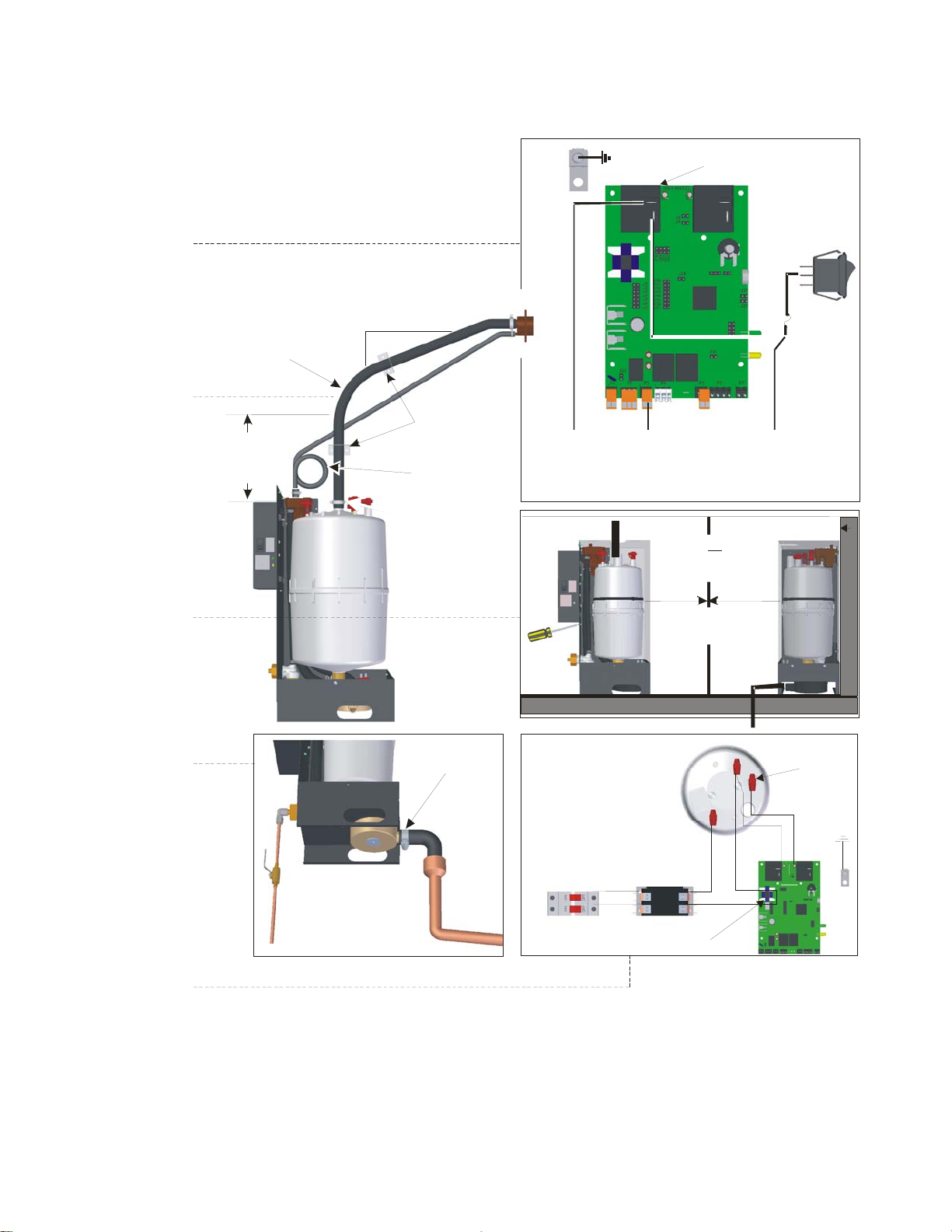
Primary Voltage Wiring
Note:
Ensure mains voltage and HWS
1
jumper settings match operating
voltage (see table below for setting,
see Figure 21 for jumper location).
Dedicated fused disconnect
2
must be installed. Fusing must
not exceed max circuit protection
as indicated on the specification
label.
Ensure that adequate powe
3
is available to carry full
humidifier amp draw as
indicated on the specification
label.
Insert wires into cylinder plugs
4
and tighten with 2mm allen wrench
to11 in-lb.
Ensure both plumbing cabinet
5
and remote electrical bracket
(if present) are grounded. Use
ground wires if required.
6
with national and local
electrical codes.
Mains Voltage Jumper HWS Jumper
600
480
380
277
240
208
Remote Electrical Bracket
ground wire
Cabinet ground wire
Secure wires with tie
wraps to tabs provided
in mounting bracket
ll wiring to be in accordance
Mains Voltage and HWS Select
J1
J2
J3
J4
J5
J6
J8
J9
3 Phase
L3
L2
L1
Disconnect
1 Phase
Cylinder Plugs
Contacto
Ground Lug
(on cabinet ATT o
on bracket REM)
Cylinde
plug with
white
marke
Current
transforme
Cylinde
plug with
white
marke
L2
19 | Installation
Disconnect
Figure 17: Primary Power Connection
Contacto
transforme
Current
Page 23

f
r
r
r
f
r
r
Control Wiring
Contacto
Contacto
Ground
24 VAC
On/Of
Safety Loop
Control
Signal
Tie wrap
wires to tabs
provided
Mandatory Wiring:
Use min. 18 AWG and keep as short as possible.
24 VAC to fuse connected to On/Off/Drain switch
1
and to power relay 0.25 in. spade connectors.
,
Ground wire from humidifier ground to air handler
2
ground.
On/Off/Safety input (24 VAC) input to point 2 of P3.
3
Optional Wiring:
Modulating control input (0-10 or 2-10 VDC)to P5
4
(J10 must be removed for modulation).
500 ohm resistor between 1-2 of P5 for mA
5
modulating control input.
Remote Fault to P2.
6
Cut-out
in cove
for wiring
Electrical Cove
(Enclosed electrical
models only)
Power Relay
Fuse+Power Relay
Contacto
Remote Fault
P2
(NO)
On/Off (Safety Loop) 24VAC
P3
Control (+)
P5
Signal (-)
24 VAC
On/Of
Drain
Switch
Fuse
Figure 18: Control Wiring
Installation | 20
Page 24

B
r
The MES2 humidifier can be operated with either On/Off controls or On/Off Safety and one
modulating input. See On/Off or Modulating Control (J10) on page 26 to configure the MES2 for
modulation. For control wiring use minimum 18 AWG and keep as short as possible. For
Modbus wiring use 18-24 AWG shielded, twisted pair 120 Ω impedance cable.
Remote fault indication is provided via a normally open relay which is closed when the controller
is in a fault condition. The dry contact may be connected to maximum of 1 amp at 24 VAC or 24
VDC.
Note: Regardless of selecting on/off or modulating control method, Nortec humidifiers
must have a closed circuit across its on/off security loop control terminal to operate.
Nortec highly recommends the use of a high limit humidistat and an air proving switch
in series for this function.
Modbus Wiring
The optional Modbus interface board can be installed onto the MES2 control board to provide
Modbus control of the MES2. In order for Modbus control to be active a jumper must be
installed on J26 of the control board. See Modbus Configuration on page 27 for information on
configuring Modbus communication.
Note:
1
Requires optional Modbus board
(PN 1509592)
2
120 Ω impedance cable.
3
4
control.
Use 18-24 AWG shielded, twisted pai
Connect shield at one end only.
J26 must be installed for Modbus
(Optional)
Modbus
RS485
Connection
Common
Modbus
Board
A
Figure 19: Modbus Wiring
21 | Installation
Page 25

MES2 Installation Checklist
Unit Serial #: _________________ No. of humidifiers: _______ Tag: _______________
Unit type: _______ __________ Voltage: ________V/_____ph
Cylinder type: Customer/Job: Address:
WATER QUALITY:
Well water City water
POWER:
Voltage, amp, fuse per Spec Label: yes no
Jumper 1-6 setting _________________
Jumper 8/9 settting ________________
Disconnect switch yes no
HUMIDIFIER MOUNTING: (Clearances around the unit Acceptable Obstruction)
Humidifier level. Cylinder removal clearance
STEAM LINE(S):
Material Diameter / Size
Slope up (min 2 in/ft). Slope down (min 0.5 in/ft)
Low point condensate traps No hose kinks / Restrictions
Type of Insulation if installed
CONDENSATE LINE(S):
P Trap min 6 in or duct press + 2 in P Trap sufficient drop to ensure flow
WATER LINE:
1/2 in to within 4ft of unit Water pressure: 30-80 psig
DRAIN LINE:
Diameter / Size ______________ Air gap within 3 ft of the unit
CYLINDER:
Seated in drain valve and secured yes no
WIRING:
Wiring connections and connectors secured yes no
CONTROLS:
On / Off / Security loop devices working correctly yes no
Jumper J10 set to
Modulating (removed)
Or
On/Off (installed)
Jumper J26 set to
Terminal block input control (removed)
Or
Modbus control (installed)
Inspected by: Date of inspection: ______/_______/______
Company:
Installation | 22
Page 26

Operation
24 User Interface
24 LED Status Lights
24 On/Off Drain Switch
25 Humidifier Configuration
26 Capacity Adjustment
26 Mains Voltage Select (J1 to J6)
26 High Water Sensor Voltage (J8 and J9)
26 On/Off or Modulating Control (J10)
26 Modulation Offset (J13)
27 Ground Fault Interrupt (GFI) (J15)
27 Modbus Control (J26)
27 Modbus Configuration
27 Modbus Addresses
30 Start Up Procedure
23 | Operation
Page 27

r
r
User Interface
LED Status Lights
The MES2 user interface includes 2 LED’s which provide information about the humidifier’s
current status.
On/Off/Drain
(Turns humidifie
On/Off and drains
Switch
the cylinder)
Green LED On
Indicates steam is being
produced
Green LED Blinking
Indicates humidifier is on
but there is no requirement
for humidity.
Yellow LED On
Indicates that water level is
high
Yellow LED Flashing
(LED will flash fixed numbe
of times then pause.)
Indicates the controller has
detected a fault and has shut down.
Number of flashes indicates
which fault. See
Troubleshooting for more
information.
Figure 20: User Interface
Yellow LED Steady On
When the yellow LED is steady on (not flashing) it indicates that the high water sensor
has interrupted filling of the cylinder. The LED is on for information only and unless it
persists for an extended period of time it does not require any action.
On/Off Drain Switch
The On/Off Drain switch turns on power to the MES2 control board or to the MES2’s drain valve.
For normal operation the switch should be set to the On position.
To manually drain the humidifier set the switch to the drain position until the cylinder is
completely empty then turn the switch off. Do not leave the switch in the drain position for
extended periods of time.
When servicing the humidifier the switch should be set to Off and the fused disconnect or
breaker should be turned to Off.
Operation | 24
Page 28

V
V
V
V
V
V
V
Humidifier Configuration
The MES2 is factory configured to operate under most conditions without the need for any
changes to its configuration. If required several settings can be made using jumpers on the
MES2’s control board. The output of the MES2 can also be reduced by using a potentiometer
on the MES2’s control board. See Figure 21: MES2 Control Board Jumpers for location of
jumpers and the capacity adjustment potentiometer.
Note: Nortec recommends not making any configuration changes unless they are required and
that any changes to the MES2’s settings be performed by a qualified technician.
J1 - J6
Mains
Voltage
Select
P11
J8 & J9
HWS Voltage
Potentiometer
Capacity
Adjustment
P11 (2-3)
Disable Self Test
J26
Modbus
Control
J13 & J15
Modulation
Offset & GFI
J10
On/Off or
Modulating
Figure 21: MES2 Control Board Jumpers
Table 6: MES2 Control Board Jumpers
Jumper Installed Removed
J1 550-600
J2 440-480
J3 380-415
J4 277
J5 220-240
J6 200-208
J8 HWS setting for 380-600 V
J9 HWS setting for 200-277
J10 On/Off Operation
J13 2-10 VDC or 4-20 mA* modulation
J15 GFI on, power relay off during drain
J26 Modbus control enabled
P11 (2-3) Self test at start up disabled
* mA modulation control requires a 500 ohm resistor installed between pins 1-2 of P5 control signal input terminal (see Figure 18:
Control Wiring.
0-10 VDC or 0-20 mA* modulation
GFI off power relay on during drain
Modbus Control disabled
Self test at start up enabled
No Affect
No Affect
No Affect
No Affect
No Affect
No Affect
No Affect
No Affect
Modulating Operation
25 | Operation
Page 29

Caution: Never adjust jumpers other than those listed in this section. Other jumpers are
factory set and must not be changed.
Capacity Adjustment
The Capacity adjustment potentiometer can adjust the capacity of the humidifier between 100%
and 20% of its rated output. (Factory setting = 100% output)
Figure 22: Capacity Potentiometer Adjustment
100%20%
Mains Voltage Select (J1 to J6)
The jumper setting must be set to match the operating voltage of the humidifier. The MES2 is
factory calibrated to provide maximum output over a range of operating voltages depending on
the setting of J1 to J6. Changing the jumper location sets the fill off amps of the humidifier to
correspond to that required at its operating voltage. One jumper only must be installed on J1 to
J6. See Table 6 for correct jumper placement.
High Water Sensor Voltage (J8 and J9)
The MES2 detects high water by measuring current flowing to its high water sensor pin (Cylinder
plug with white marker). To insure accurate detection of current, the High Water Sensor (HWS)
circuit must be configured using J8 and J9 to match the operating voltage. A jumper must be
installed on either J8 or J9, not on both. See Table 6 for correct jumper placement.
On/Off or Modulating Control (J10)
The MES2’s output can be controlled by either an On/Off humidistat or a modulating
humidistat. To set the MES2 to operate with a modulating humidistat remove Jumper J10.
(Factory setting = jumper Installed, On/Off operation)
J10 Removed– Modulating operation, the controller monitors the demand signal on
terminal point 4 of the control terminal strip and adjusts humidifier output to match it. For
mA control install a 500 ohm resistor across pins 1 and 2 of P5 control signal input terminal.
J10 Installed - The MES2 is configured for On/Off operation. The controller will ignore any
modulating signals even if they are connected.
Modulation Offset (J13)
The MES2 controller can be configured to work with a modulating humidistat with 4-20 mA or 210 VDC output. Modulation offset can be configured with jumper 13. (Factory setting = Jumper
Removed, 0-10 VDC or 0-20 mA control signal). See Table 6 for correct jumper placement.
Operation | 26
Page 30

Ground Fault Interrupt (GFI) (J15)
Ground current leakage can occur when the humidifier performs drains. With jumper J15 the
MES2 can be configured to turn off the power to the electrodes whenever a drain takes place.
See Table 6 for correct jumper placement.
Modbus Control (J26)
The MES2 can be controlled via its Modbus interface. When configured for Modbus control the
MES2 ignores On/Off and modulation control inputs on its control terminal strip and operates
strictly based on data received via Modbus. The Modbus interface can also be used to make
some configuration changes and to read the status of the MES2. See Table 7.
J26 Removed – The Modbus interface is turned off and the humidifier operates based on
control inputs at its terminal strip.
J26 Installed – The Modbus interface is turned on. The humidifier will operate strictly based
on control inputs received via Modbus and can be configured and queried using the Modbus
interface.
Disable Self Test (P11, 2-3)
On start up the MES2 performs a self test that activates all outputs briefly including the remote
fault output. To disable the self test the jumper installed on P11 pins 2-3 can be installed.
Modbus Configuration
Contact Factory – 1-866-NORTEC-1.
Modbus Addresses
The following table lists the MES2 parameters that are available via Modbus. 4XXXX
parameters can be read and written by the Modbus master. 3XXXX parameters are read only.
Table 7: Modbus Addresses
Function Description Address Details
Output
Control
Set Output Sets the desired steam output from 0-
OFF
Disables the humidifier and places the
humidifier in standby mode
ON
Enables the humidifier (humidifier will
operate based on the SET OUTPUT input)
100% This value shall be zero after a
microprocessor reset
40002 255: inhibit actions of humidifier
0: allow normal operation
40004 Remotely set humidity reading over
network. Value of 0 to 100 (per cent). If
no network signal for N minutes, reverts
to 0.
27 | Operation
Page 31

Table 7: Modbus Addresses (Continued)
Function Description Address Details
Force Drain When written to (FF), will interrupt the
humidification process and activate the
humidifier drain valve. After 20 minutes
the controller will reset this value (00).
After a microprocessor reset, the default
setting shall be (00)
Reset Run
Hour
Counter
Set Modbus
address
Set Modbus
Baud rate
Set Modbus
parity
Units Required by the control board for
Unit type Required by the control board for current
Unit voltage Required by the control board for
Unit phase Required by the control board for current
Electrode
current
Resets the humidifier controller’s run
hour counter to zero hours
Change the humidifier controller’s
MODBUS address. Range is 1-247. This
setting shall be non-volatile with a
default setting of 1.
Changes the humidifier’s baud rate.
Range is 4800, 9600, and 19200 B/sec.
This setting shall be non-volatile with a
default value of 9600 B/sec.
Change the humidifier controller’s
MODBUS parity. Range is None, Even,
Odd This setting shall be non-volatile with
a default setting of Even.
capacity calculations
and capacity calculations
current and capacity calculations
and capacity calculations
The value of the electrode current in
Amps
40005 255 will start the process, 0 will be
accepted, to clear if the request has not
been cleared itself
40006 255 will start the run hours counter
process. 0 will be accepted to clear the
run hours counter.
40201 The value changes will only take effect
following a hardware reset of the control
board.
40202 The value changes will only take effect
following a hardware reset of the control
board
40203 The value changes will only take effect
following a hardware reset of the control
board
40204 0=LBS, 1=KG
40205 Depending on the setting in UNITS
(Modbus: 40204) Hex value
representing maximum unit capacity
(100% fill off amps)
40206 Hex Value Unit Type
0 110-120
1 208
2 220-240
3 230
4 277
5 347
6 380
7 400
8 415
9 440-480
A 550-600
40207 Bit Allocation
Single phase = 1
Three phase = 2
Three phase (6 electrode) = 4
30104 Hex value representing the humidifies
current in amps Resolution: 0.10 amps
Example: 015F (hex) = 35.1 Amps
Operation | 28
Page 32

Function Description Address Details
Steam
output
Run hour
counter
Humidifier
state
Alarms The humidifier shall describe any faults
Maximum
production
Firmware
version
The current steam output in Kg/Hr. or
LBS/hr See UNITS (Modbus 40031)
The number of hours the humidifier has
been in operation since the last time the
run hour counter was reset
Describes the current state of the
humidifier and it’s I/O’s Contactor
ON/OFF Fill Valve ON/OFF Drain Valve
ON/OFF
Too long to fill Excess Current End of
cylinder life No current
The rated maximum steam production
for the humidifier
The firmware version of the humidifier
controller
30105 Hex value representing the humidifies
steam output in kg/hr Resolution: 0.10
kg or LBS Example: 013B (hex) = 31.5
kg/hr or LBS/hr
30106 Hex value representing the number of
humidifier operational hours since the
last reset. Resolution: 5 minutes
Maximum count: 5460 Hours. Example:
07D0 = 2000 hours
30107 Bit Allocation Note More than one bit
can be active at any time. Contactor on
= 1 Fill valve on = 2 Drain valve on = 4
30108 Bit Allocation Note More than one bit
can be active at any time.
Too long to fill = 1
Excess current = 2
End of cylinder life = 4
No Current = 8
30111 Value written into Unit type (40205) is
also stored here
30113 Packed BCD version3.52 would be
0x0352
29 | Operation
Page 33

Start Up Procedure
1 Examine the humidifier and installation for damage and or improper installation.
Warning: Damaged Units or improperly installed units must not be operated. Damaged or
improperly installed units may present a danger to persons and property.
2 If enclosed plumbing option is installed ensure that the front cover is in place and secured
with its retaining screw.
3 Open the supply water shut off valve.
4 Turn on the mains power using the installed disconnect.
5 Turn the On/Off switch to the “On” position.
The humidifier will perform a self-diagnostic sequence during which the LED’s and internal
components will be momentarily activated.
If an error is detected during the self-diagnostic sequence the humidifier will not start. The
yellow status LED will flash in sequence to indicate the detected fault. See Table 7:
Troubleshooting MES2 Faults on page 43 for information on diagnosing and correcting
faults.
After the system test the humidifier is in normal operation mode.
6 Check and adjust the control setpoint on the control and high limit humidistat.
7 When the external humidistat generates a demand for humidity and the security loop is
closed the green humidifying LED on the front of the humidifier will light up, the power relay
on the control board will engage, the fill valve will activate (after a delay) and the cylinder will
slowly fill with water.
Note: While the cylinder is filling with water there should be no water flowing down the drain. If
water is flowing down the drain it can indicate excessive backpressure or a leaking drain
valve. See chapter on troubleshooting starting on page 39.
8 It can take some time for the water to be heated up by the submerged electrodes and for
steam to be produced. Once the fill valve shuts off after reaching the appropriate water
level, the water in the cylinder will start to heat up until steam is generated.
Note: If operated on low conductivity water it may take several hours for the MES2 to
reach full output capacity. This is normal. During this time the humidifier will not perform
any drains and the conductivity of the water in the cylinder will increase.
Operation | 30
Page 34

Maintenance and
Servicing
32 Required Maintenance
32 Cylinder Spent Fault
32 Replacement Cylinder
33 Removing the Cylinder
34 Drain Valve Cleaning
35 Installing the New Cylinder
36 Extended Shutdown
36 Starting After Extended Shutdown
37 MES2 Maintenance Checklist
31 | Maintenance and Servicing
Page 35

r
f
r
Required Maintenance
The MES2 humidifier has been designed to require very little maintenance. Regular
maintenance consists of checking the humidifier to insure it is in good condition, replacing the
cylinder when the software advises that the cylinder is spent and cleaning out the drain valve
whenever the cylinder is replaced.
Cylinder Spent Fault
When the cylinder is spent the MES2 will stop operating and the yellow LED will flash in a
repeating pattern of 4 flashes. At this time the cylinder must be replaced. See Table 7:
Troubleshooting MES2 Faults on page 43 for more information on other flash sequences.
The steam cylinder is disposable and must be replaced at end of cylinder life. Cylinder life is
dependent on water supply conditions and humidifier usage.
Caution: Failure to replace the cylinder at the end of cylinder life will result in improper
operation and may result in damage to the humidifier. Nortec is not responsible for any
damages resulting from, or attributed to, the failure to replace a spent cylinder (see
Manufacturer’s Warranty).
Note: Nortec recommends keeping a replacement cylinder in stock throughout the
humidification season. This will prevent possible downtime when the humidifier reports
cylinder end of life.
Replacement Cylinder
The label on the existing cylinder identifies the cylinder type in its top left corner. When ordering
a cylinder always quote the three or five digit model number on the label, the humidifier’s serial
number, and the humidifiers voltage. Serial number and voltage are located on the
specification label on the left side of the humidifier.
Steam Outlet
Secure steam hose to
High Water Sensor Pin
Has a plastic collar
around it. Connect
orange high wate
sensor wire here.
outlet with hose clamp.
Electrode Pin
Connect color coded cylinde
plugs to pin with corresponding
color label. There may be 2 or 3
connections depending on
cylinder.
The spring loaded plug should
fit snugly on the pin. Replace i
loose or any signs of damage.
Label
Identifies cylinder type in
top left. Always replace
cylinder with the same
model.
Figure 23: MES2 Cylinder
Maintenance and Servicing | 32
Page 36

Removing the Cylinder
Warning
Check to see if yellow service LED is flashing (see Figure 20: User Interface on
page 24) then disconnect main power at the external disconnect before any
servicing.
The inside of the humidifier’s cabinet contains high voltage components and
wiring. Access should be limited to authorized personnel.
1 Drain the existing cylinder by switching the On/Off/Drain switch to the Drain position. Let
the humidifier drain until no more water is flowing out to drain (usually not more than 10
minutes).
2 Turn the humidifier On/Off/Drain switch to off.
3 Close supply water shut off valve.
4 Turn off power to the humidifier with the external disconnect.
5 If enclosed plumbing option is installed remove the screw securing the front cover.
6 Remove the cylinder plugs from the cylinder pins by pulling vertically.
7 Using a flat screwdriver loosen the hose clamp where the hose is connected to the cylinder.
8 Using a small flat screwdriver press the tab on the cable tie holding the cylinder in place and
pull the cable tie open.
9 Tip the top of the cylinder forward to pivot it out of the steam hose. When free of steam
hose lift the cylinder out.
Cylinder Plug
lift vertically
Hose Clamp
Tilt cylinder
forward to clear
hose and then
lift from drain
valve.
Cable Tie
On/Off/Drain Switch
33 | Maintenance and Servicing
Figure 24: Cylinder Removal
Page 37

Drain Valve Cleaning
Always clean the drain valve before installing a new cylinder. Scale from the spent cylinder may
have fallen into the drain valve and could prevent its proper operation. To properly clean the
drain valve it must be removed and disassembled.
Note: Be sure to reattach the green ground wire to reduce the risk of electrical shock.
1 Disconnect spade terminals from the drain valve.
2 Remove the screw holding the green ground wire and the two screws holding the valve to
the drain pan.
3 Squeeze the tabs of the spring clamp holding the hose to the drain valve and slide it up the
hose. Pull hose from drain valve. Lift the drain valve from the drain pan.
4 Unsnap red coil cap on solenoid and remove the solenoid from the valve.
5 Loosen brass nut holding actuator to plastic housing with a wrench and disassemble
actuator.
6 Clean actuator components and valve housing (inlet port, outlet port, and cylinder port). Put
new o-ring that was supplied with new cylinder into valve.
7 Reassemble actuator making sure tapered end of spring is oriented as shown Figure 26.
Tighten brass nut 1/4 turn past hand tight.
8 Clean out end of hose and reattach to valve. Slide hose clamp back in place and place valve
into drain pan.
9 Secure valve with 2 screws and attach green ground wire to solenoid.
Cylinder Port
and O-ring
Ground Wire
Hose and
Hose Clamp
Screws
Solenoid
Brass Nut
(Actuator)
Figure 25: Drain Valve
Spade Connectors
Maintenance and Servicing | 34
Page 38

Plunger
Spring
(Note Orientation)
Sleeve
and
Solenoid
Figure 26: Drain Valve Actuator Assembly
Installing the New Cylinder
CAUTION: Make sure the new cylinder is the same model as the one that was
removed. Model number is on top left corner of cylinder label.
1 Insert cylinder into drain valve. Tilt cylinder forward and fit end of steam hose to steam
outlet. Tip cylinder back into place.
2 Secure cylinder with the reusable cable tie. Tighten hose clamp being careful not to over
tighten and crush the plastic cylinder steam outlet.
3 Attach color-coded cylinder plugs to the corresponding color-coded cylinder pin. Push down
completely. Connect high water sensor plug. Spring-loaded plugs should fit snuggly onto
the cylinder pin. Replace if they are loose or damaged.
4 If enclosed plumbing option is installed replace the humidifier cover and secure with screw.
5 Turn on power to humidifier with the external disconnect.
6 Open supply water shut off valve.
7 Turn the humidifier On/Off /Drain switch to On.
35 | Maintenance and Servicing
Page 39

Extended Shutdown
Should it be required to disconnect power to the humidifier for a period of extended shut-down,
always drain the cylinder first. Otherwise, the electrodes are subject to harmful corrosion which
drastically shortens the cylinder life.
1 Switch the On/Off/Drain Switch to the Drain position.
2 Wait until the humidifier is completely drained (usually takes less than 10 minutes).
3 Turn the On/Off /Drain switch to the off position.
4 Shut off power to the humidifier with the external disconnect.
5 Close the supply water shut-off valve.
Caution:
Do not leave the switch in the DRAIN position indefinitely as the drain coil could burn
out.
When disconnecting power to the humidifier for an extended period of time drain the
cylinder first to prevent harmful corrosion.
Note: As long as the MES2 is powered, it will automatically drain the cylinder when there
has not been a call for humidity for an extended period of time. This feature will reduce or
prevent the possibility of corrosion of the electrodes and the accumulation of algae and
bacteria growing in the cylinder. The cylinder will remain empty until there is a call for
humidity at which time the fill valve will open and refill the cylinder. The unit will go
through its normal process for optimum operation.
Starting After Extended Shutdown
1 Check to see the humidifier has not been damaged and the installation has not been
altered.
2 Open the supply water shut-off valve.
3 Turn on the power to the humidifier with the external disconnect.
4 Turn the On/Off/ Drain switch to the On position.
5 Follow the start up procedure in the section titled Start Up Procedure on page 30.
Maintenance and Servicing | 36
Page 40

MES2 Maintenance Checklist
Model #: _________________
Serial #: _________________ Tag: ________
Cylinder #:
CHECK CYLINDER
Cylinder spent), yellow LED flashing 4 times in sequence.
(If Yellow LED is On and cylinder is not new then cylinder will have to be replaced soon.)
REPLACE CYLINDER
Cylinder drained.
Disconnect open, On/Off/Drain switch off, water shut off valve closed, cover removed.
Cylinder removed
Drain valve removed / cleaned / new O-Ring installed
Drain valve cleaned / installed / ground wire attached.
New Cylinder Installed New cylinder model #
Cylinder plug colors match cylinder dots.
Cylinder plugs snug and in good condition.
High Water Sensor plug snug and in good condition.
Steam hose attached.
Cover replaced, water shut off valve open, On/Off /Drain switch On, Disconnect Closed
(Should be same as removed cylinder)
SYSTEM CHECK
Yellow Led flashing? No Yes Flash Sequence?
(See Troubleshooting Chapter for actions if yellow LED is flashing)
Primary power disconnect turned off
Cylinder plugs snug and in good condition.
Electrical wiring not loose and in good condition,
Steam hoses and steam lines in good condition / No kinks in hose,
No Signs of water leaking around humidifier, steam line, condensate returns,
Cover replaced, water shut off valve open, On/Off /Drain switch On, Disconnect Closed
Inspected by: Date of inspection: _______/_______/______
Company:
37 | Maintenance and Servicing
Page 41

Maintenance and Servicing | 38
Page 42

Troubleshooting
40 Organization of Troubleshooting Chapter
40 Troubleshooting Requirements
41 General Troubleshooting
41 Humidifier
42 Steam Distributors
42 Modbus
42 MES2 Faults
43 LED Flash Sequence
43 Clearing a Fault
45 MES2 Wiring Diagram
39 | Troubleshooting
Page 43

Organization of Troubleshooting Chapter
The troubleshooting chapter is broken down into 2 sections.
General Troubleshooting Deals with troubleshooting incorrect humidifier operation,
steam line and plumbing issues without any control
software faults.
Humidifier Warnings and Faults Deals with faults that are generated by the humidifier’s
control software.
CAUTION: Be aware, when troubleshooting, that the humidifier is powered by high voltage
and familiarity with both good practices and wiring of the humidifier is recommended.
Any troubleshooting should be done by qualified personnel.
NOTE:
Check if yellow service LED is flashing before turning off the humidifier to determine if
a fault has occurred. See Figure 20 on page 24 and Table 7 on page 43.
Most humidifier faults are not caused by faulty equipment but rather by improper
installation. A complete fault diagnosis always involves a thorough examination of the
entire system. Often, the steam hose connection has not been properly executed, or
the fault lies with the humidity control system.
Troubleshooting Requirements
Ensure the installation meets the installation requirements outlined in the Installation
Chapter of this manual.
Familiarize yourself with the operation of the humidifier by reading the Operation Chapter on
page 24 and the section describing How the Humidifier Works on page 9 in this manual.
A generic copy of the MES2 wiring diagram is included at the end of this chapter for
reference purposes.
When contacting your local representative or Nortec for troubleshooting assistance, please
ensure the serial number has been obtained for reference purposes.
Troubleshooting | 40
Page 44

General Troubleshooting
The following section provides general guidelines for troubleshooting the MES2 humidifier and
auxiliary components. For detailed troubleshooting information refer to the manuals that were
provided with auxiliary equipment and to Table 7: Troubleshooting MES2 Faults on page 43.
Humidifier
Table 6: General Troubleshooting
Symptom Cause Corrective Action(s)
Nothing happens when On/Off
switch is turned on.
Humidifier will not humidify or
not reaching RH setpoint
1 Fuse blown 1 Check inline fuse between
On/Off/Drain switch and control
board.
2 Incorrect Voltage 2 Check voltage supplied to
On/Off/Drain switch is 24 VAC.
3 Mains power turned off 3 Turn on mains power.
1 Safety loop open. No 24 VAC at
2.
2 No demand signal (If J10
removed for modulation)
3 Not configured correctly for
On/Off or modulating control
4 Capacity has been manually
limited
1a Check if there is 24 VAC at point 2 of
Terminal P3 on the control board.
1b Check if air handler is outputting 24
VAC run signal.
1c Check wiring and operation of On/Off
devices connected in series between
output calling for humidity and point 2
of terminal P3.
2 Check voltage between P5 and
ground. 25% of full-scale signal must
be present for humidifier to start.
3 Check that J10 on control board is
removed for modulating control and
installed for On/Off control.
4 Check Manual Capacity adjustment
potentiometer. Clockwise increases
capacity.
Humidifier has faulted and
yellow LED is flashing
41 | Troubleshooting
5 Low conductivity water
6 Humidifier undersized
1 Software has detected an
abnormal condition
5 Check if yellow LED is on. If operated
on low conductivity water it may take
several hours for the MES2 to reach
full output capacity. This is normal.
During this time the humidifier will not
perform any drains and the
conductivity of the water in the
cylinder will increase.
1 Refer to Table 7: Troubleshooting
MES2 Faults.
Page 45

Steam Distributors
Symptom Cause Corrective Action(s)
Distributor spitting out water
1 Distributor not level 1 Use support at end of distributor to
ensure it is level.
2 “P” Trap too close to distributor 2 “P” Trap must be a minimum of 12 in
(30 cm) below the distributor to
ensure flow. Relocate if required.
3 Condensate line not sloped
sufficiently
4 Trap blocked 4 Check that water flows through trap.
5 Steam line not insulated 5 If steam line is long condensate build
6 Incorrect steam line installation 6 Check that steam line has been
7 Humidifier foaming and foam
carried up steam line.
3 Sufficient slope to insure flow is
required. Reinstall if required.
Clear out if blocked.
up could overload distributor
condensate port. Insulate line to
improve efficiency and install
additional condensate traps as
required.
installed with condensate traps and
slope per installation instructions on
page 16.
7a Check if foaming caused by short
cycling.
7b Check if foaming caused by blocked
or restricted drain.
7c Check if steam line is causing back
pressure and preventing proper filling.
Condensation in Air Handler 1 Installation clearances not
observed
2 Design conditions changed 2 Check supply air temperature and
3 High limit not functioning 3 Check setting and operation of high
Modbus
Symptom Cause Corrective Action(s)
No Modbus Communication
1 Incorrect Wiring 1a Use 18/24 AWG Shielded Twisted
2 Incorrect Communication
Parameters
3 Noise interference 3a Route data cable away from noise
1 Refer to distributor installation manual
for required clearances. Relocate
distributor if required.
humidity to determine if conditions
have changed.
limit. Replace if defective.
Pair, 120 Ω cable.
1b. Connect shield to one end only.
1c. Check polarity of data wires.
2 Defaults are 9600 B/sec, Modbus
Address 1, Even Parity
generating devices.
3b Install an RS485 repeater.
Troubleshooting | 42
Page 46

MES2 Faults
The self-diagnostic system built into the MES2 is continually monitoring the operation of the
humidifier. When an abnormal condition occurs that cannot be self corrected by the software
the MES2 will turn off power to the cylinder, drain the cylinder, and annunciate the fault using
the yellow status LED.
LED Flash Sequence
To differentiate between different fault conditions the yellow LED is flashed in different
sequences. Table 7 lists MES2 faults, their meaning, possible causes, and corrective actions.
Clearing a Fault
Check the flash sequence against the list of fault messages and take any necessary actions
to correct the cause(s) as outlined in Table 7: Troubleshooting MES2 Faults.
Power cycle the humidifier with the On/Off switch. Wait 3 seconds between off and on.
Table 7: Troubleshooting MES2 Faults
Yellow LED System Detected Cause Corrective Action(s)
1 flash
Excess Current
Current has exceeded
130% of max
1 Drain blocked water over
concentrated
2 Drain solenoid not energized,
water over concentrated
3 Filling too fast, fill valve
damaged
4 Water supply too conductive 4a Contact Nortec
5 Humidifier short cycling 5a Check if high limit or other
1 Clean the drain line and drain
valve.
2 Check and correct wiring to
drain valve.
3 Check fill rate and replace the
fill valve if needed.
representative for
recommendation on alternate
cylinder
4b Change the water supply
On/Off control is cycling
On/Off in less than 5
minutes. Check location and
setting of high limit.
5b Reduce the output by
turning down the capacity
potentiometer.
5c If modulating control check
if controller Pband too tight.
5d Check for temperature
swings.
43 | Troubleshooting
6 Wrong cylinder installed 6 Install correct cylinder model
7 Cylinder Spent but not
detected by software
8 Condensate from other
source
9 Back pressure 9 Eliminate back pressure
7 Replace the cylinder (see
maintenance chapter)
8 Remove condensate returns
other than from steam line.
Page 47

Table 7: Troubleshooting MES2 Faults (Continued)
Yellow LED System Detected Cause Corrective Action(s)
2 flashes
No Current
Fill valve activated for
long time but high water
level not reached.
Fill should be faster than
1” per minute.
1 Drain valve leaking or stuck
open
1 Clean drain valve or replace
(see maintenance chapter)
2 Water shut off valve closed 2 Open shut off valve
3 Fill Valve strainer blocked 3 Clean out strainer on fill valve
4 High system back pressure 4a Check for kinked hose
4b Check for proper
condensate removal (see
installation chapter)
5 High water sensor not
connected
5 Check that cylinder plug with
white marker is connected to
short electrode with a plastic
collar around it and to control
board.
6 Low water conductivity 6a Check conductivity of water.
If less than 150
microsiemens contact factory
for recommendation.
6b Add 1/4 teaspoon of salt to
fill cup and restart unit.
1 Primary wire not looped
through current transformer.
1 Open disconnect, rewire
primary wire through current
transformer.
3 flashes
4 flashes
No Current, High Water
Water level at top of
cylinder with no current
Cylinder Spent
Electrodes covered with
scale.
2 1 phase of 3 phase supply
blown
3 High water sensor plug is on
an electrode pin.
4 Cylinder plugs installed
incorrectly
1 Cylinder electrodes are
calcified.
2 Software incorrectly detected
cylinder is spent
2 Check that all phases are
energized.
3 Install high water senor plug
on cylinder pin with collar
around it.
4 Check that cylinder plugs
colors match markers next to
electrodes on cylinder and
that white marked cylinder
plug is connected to pin with
collar around it.
1 Replace cylinder with same
model number (see
maintenance chapter)
2a If fault has occurred shortly
after start up then check for
low water conductivity. (See 2
flashes cause 6)
2b Check if water in cylinder is
foaming. If yes see 1 flash Excess current causes.
Troubleshooting | 44
Page 48

MES2 Wiring Diagram
Modulation:
Remove J10 for 0-10 VDC
Remove Jumper J10 and place it on J13 for 2-10VDC
Control Signal
(0-10 Vdc, 2-10 Vdc)
(-) (+)
DRAIN
FILL
ON/OFF
Safties
S
3 Amp
Fuse
24 Vac Hot
24 VAC Common
Primary
Terminal
Block
(by others)
L1
L2 L3
Yellow LED
Green LED
Common
B
A
Install J26 For
Modbus Control
Calibration
(Do not ajust!)
Capacity
adjust
J10
RS485/TTL
Modbus Interface
Board (1509592)
R52
Mains Voltage
Select Jumpers
J6 208V
J5 230V
J4 277V
J3 380-415V
J2 460V
J1 575V
3
2
1
J13
HW Sensor Jumpers
J9 Low Voltage 200-277V
J8 High Voltage 380-600V
Drain
OFF
ON
Fault
Indication
N.O
3
1
J7
J6
J5
J4
J3
J2
J1
2
1509591
Contactor
24 Vac
(by others)
45 | Troubleshooting
J9
J8
2 or 3 electrode cylinder
NOTE: Dotted lines denote wiring by others with the exception of
Primary Voltage Wiring ( PVW ) units which will come with all
primary wiring to the cylinder and 10’ of wiring to run the electrical
back to the contactor
MES2 with Optional Modbus board
WIRING DIAGRAM
DIAGRAM NUMBER 2553788 Rev. B
DATE August 18, 2010
Figure 27: MES2 Wiring Diagram
Page 49

Exploded View and Spare Parts List
Spare Parts| 46
Page 50

MES2 Spare Parts
11
8
7
10
1
2
5
3
4
9
6
16
17
Figure 28: MES2 Spare Parts
47 | Spare Parts
12
13
14
15
Page 51

Table 8: MES2 Spare Parts List
1 1 1
1 1 1
1 1 1
3 3 3
1 1 1
1
1
1
1 1 1
1 1 1
1 1 1
1 1 1
1
1
1
1 1 1
1 1 1
1 1 1
1 1 1
1 1 1
1 1 1
1 1 1
Item Description Part No. 5 lb/hr
2.3
kg/hr
10 lb/hr
4.5
kg/hr
15 lb/hr
6.8
kg/hr
20 lb/hr
9.1
kg/hr
25 lb/hr
11.4
kg/hr
30 lb/hr
13.6
kg/hr
1 PCB MES2, 208-600V, 1 PH 2554100 2554101 2554102 2554104
PCB MES2, 208-600V, 3 PH 2554103 2554105 2554106 2554107
2 PCB Modbus Interface 1509592
3 Switch Bracket 2554036
4 Switch Rocker SPDT 1323097
5 Connector, 2 Pole 1703972
Connector, 3 Pole 1703973
6 Enclosed Plumbing
Option
2554073
2554074
2554075
2554076
1 1 1
1 1 1
1 1 1
3 3 3
1 1 1
1
1 1
7 Cylinder To order quote 3 digit number on existing cylinder, or Ser. No, Model, & Voltage
8 Cyl. Plug Black Marker 1510046
Cyl. Plug Red Marker 1510047
Cyl. Plug White Marker 1510048
Cyl. Plug Yel. Marker 1510049
9 Tie Wrap Reusable 1513003
1 (Three phase humidifiers only)
1 1 1
1 1 1
1 1 1
1 1 1
10 Fill Cup Assembly 2554069
2554070
2554071
2554072
11 Drain Valve and Coil 1456000
12 Gasket Drain Canal 1631026
13 Drain Canal Round 1102503
14 Washer Drain Canal 1325046
15 Screw #6-32x1.5 1325064
16 Fill Valve 005-020 1321061
Fill Valve 025-030 1321062
17 Fitting 3/4 to 1/8 1495072
1
1 1
1 1 1
1 1 1
1 1 1
1 1 1
1 1 1
1
1 1
1 1 1
Spare Parts| 48
Page 52

Page 53

Warranty
Nortec Humidity Ltd. (hereinafter collectively referred to as THE COMPANY), warrant for a
period of two years after installation or 30 months from manufacturer’s ship date, whichever
date is earlier, that THE COMPANY’s manufactured and assembled products, not otherwise
expressly warranted (with the exception of the cylinder), are free from defects in material and
workmanship. No warranty is made against corrosion, deterioration, or suitability of substituted
materials used as a result of compliance with government regulations.
THE COMPANY’s obligations and liabilities under this warranty are limited to furnishing
replacement parts to the customer, F.O.B. THE COMPANY’s factory, providing the defective
part(s) is returned freight prepaid by the customer. Parts used for repairs are warranted for the
balance of the term of the warranty on the original humidifier or 90 days, whichever is longer.
The warranties set forth herein are in lieu of all other warranties expressed or implied by law. No
liability whatsoever shall be attached to THE COMPANY until said products have been paid for in
full and then said liability shall be limited to the original purchase price for the product. Any
further warranty must be in writing, signed by an officer of THE COMPANY.
THE COMPANY’s limited warranty on accessories, not of the companies manufacture, such as
controls, humidistats, pumps, etc. is limited to the warranty of the original equipment
manufacturer from date of original shipment of humidifier.
THE COMPANY makes no warranty and assumes no liability unless the equipment is installed in
strict accordance with a copy of the catalog and installation manual in effect at the date of
purchase and by a contractor approved by THE COMPANY to install such equipment.
THE COMPANY makes no warranty and assumes no liability whatsoever for consequential
damage or damage resulting directly from misapplication, incorrect sizing or lack of proper
maintenance of the equipment.
THE COMPANY makes no warranty and assumes no liability whatsoever for damage resulting
from freezing of the humidifier, supply lines, drain lines, or steam distribution systems.
THE COMPANY retains the right to change the design, specification and performance criteria of
its products without notice or obligation.
Warranty | 50
Page 54

U.S.A.
1860 Renaissance Blvd.
Sturtevant, WI 53177
826 Proctor Avenue
Ogdensburg, NY 13669
CANADA
2740 Fenton Road
Ottawa, Ontario K1T
TEL: 1.866.NORTEC1
EMAIL: nortec@humidity.com
WEBSITE: www.humidity.com
3T7
 Loading...