

Noritz SCU-301-24M Installation Manual
System Controller
CAUTION
SCU-301-24M
In order to use this product safely,
read this installation manual carefully
and follow the installation instructions.
Installation Manual
Potential dangers from accidents during installation and use are divided into the following two categories.
Closely observe these warnings, they are critical to your safety.
WARNING
CAUTION
WARNING indicates a potentially hazardous situation which, if not avoided, could result
in death or serious injury.
CAUTION indicates a potentially hazardous situation which, if not avoided, may result in
minor or moderate injury.
Disconnect
Power
Ground
Requests to Installers
WARNING
•
Failures and damage caused by erroneous work or work not as instructed in this manual are not covered by the warranty.
• Refer to installation manual attached to the appliance as well.
• Check that installation was done in accordance with this Installation Manual upon completion.
• After completion of installation, be sure to hand this Installation Manual to the customer.
• When you fasten the screws on the terminals (Warning lamp terminal and so on),do not use electric drivers,
impact drivers and so forth.Tightening with excessive force may cause the terminals to be damaged and lead
to failures.
In order to use this product safely, read this installation manual carefully and follow
the installation instructions.
Contents
1. Included Accessories .................................................2
2. Required Accessories ................................................2
3. Introduction ................................................................3
4. Installing the System Controller .................................4
5. Wiring Diagram, System Diagram.............................. 7
6. Remote buttons and display overview .......................8
7. Remote initial setup ..................................................10
8. Recirculation Pump Timer Setup ..............................14
If at any time during the installation and setup of this product you have questions or concerns, please contact Noritz America
Engineering & Service at 866-766-7489 or visit http://support.noritz.com/.
SBA8938
Rev. 5/12
9.
System Check Button
10. Maintenance Monitors and Additional Settings
11. Additional Remote features
12. Additional System Controller Features
13. System design, Gas, and Water piping
14. Follow-up Service ....................................................29
15. Dimensions .............................................................. 30
──
................................................... 16
..........................................
.......................
......................
*SBA8938*
.........
17
19
21
25
1. Included Accessories
Part Shape Qty Part Shape Qty
Tapping screw 5
*1 Attached in the system controller.
*1
Assembly &
Setup Instructions
Check for any missing items
before starting installation.
2. Required Accessories
Name Usage Qty
Remote controller
RC-9018M
Remote controller Cord
RC-CORD10
RC-CORD26
CAUTION : Be sure to use the remote controller cord as listed above. If a different cord is used, the equipment may fail or not
operate properly.
* Always necessary. 1
-The communication cord between the system controller and the
remote controller can be lengthened up to a maximum total length
of 450 feet.
-The communication cord between the system controller and each
water heater can be lengthened up to a maximum total length of
45 feet.
Total number of units
in system + 1
1
When two or more multi-unit systems are installed in parallel
One remote controller is necessary for each multi-unit system (i. e. 3 multi-unit systems will require 3 system
controllers and 3 remote controllers). Each system will have separately wired remote controller cords.
For the combined use pattern
A. When there is no circulation pipe (standard type)
Number of units
13 to 24 SCU-301-24M RC-9018M
System controller
Remote controller
B. When there is a circulation pipe
Condition
Recirculation type
(circulation heat-retention with external pump)
Storage Tank Recirculation type
(circulation heat-retention with external pump)
Number of units
13 to 24 SCU-301-24M RC-9018M
13 to 24 SCU-301-24M RC-9018M
System controller
Remote controller
──
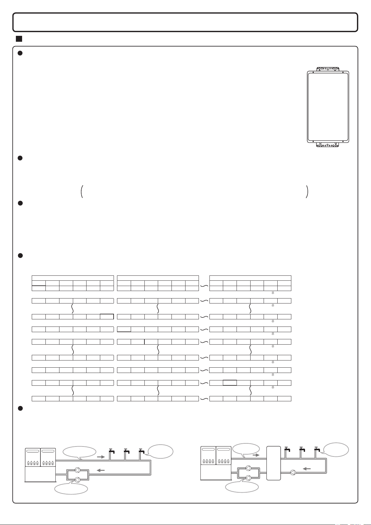
3. Introduction (see list of points below)
<Recirc>
<Tank recirc>
Introduction to the “SCU-301-24M” System Controller
Overview
This manual is intended to provide instruction for the installation, operation, and features of the SCU-301-24M system
controller. It is divided into 4 main sections:
1. Installation of the SCU-301-24M system controller
2. Initial programming of the RC-9018M remote controller
3. Additional features of the RC-9018M remote controller and the SCU-301-24M system controller
4. Plumbing diagrams and general information about water and gas piping
Please read this manual carefully and follow the instructions as written.
If you have any questions, please contact Noritz Engineering & Service at 866-766-7489 or
visit http://support.noritz.com/.
Basic Operation
The SCU-301-24M system controller is used to combine 13 to 24 Noritz heaters into a single “multi-unit system.” The
system controller stages units on and off based on hot water demand and rotates their operation to ensure even usage.
It also has two additional modes which optimize the system for operation with a recirculation line or storage tank.
Note: for systems of 1 to 6 units please use the SC-301-6M system controller
Note: for systems of 7 to 12 units please use the SC-301-12M system controller
Unit Staging
Staging allows the multi-unit system to track hot water demand from the minimum ow rate of a single unit up to the
maximum output of several units. When the primary ring heater reaches ~50% of its maximum output, the system
controller activates the next unit in the system. When both these units reach ~50% of their maximum output, a third
unit is activated and so on. The SCU-30-4M may also be congured to activate two heaters during primary ring to
allow for rapid initial hot water demand.
Unit Rotation
The SCU-30-4M system controller rotates operation of the primary ring heater every 8 hours of combustion time or
up to 24 hours of plug-in time. This helps to ensure even usage of all units.
UNIT1 UNIT2 UNIT3 UNIT4 UNIT5 UNIT6 UNIT7 UNIT8 UNIT9
1st 2nd 3rd 4th 5th 6th 7th 8th 9th 10th 11th 12th 19th 20th 21st 22nd 23rd 24th
6th 1st 2nd 3rd 4th 5th 12th 7th 8th 9th 10th 11th 24th 19th 20th 21st 22nd 23rd
2nd 3rd 4th 5th 6th 1st 8th 9th 10th 11th 12th 7th 20th 21st 22nd 23rd 24th 19th
19th 20th 21st 22nd 23rd 24th 1st 2nd 3rd 4th 5th 6th 13th 14th 15th 16th 17th 18th
24th 19th 20th 21st 22nd 23rd 6th 1st 2nd 3rd 4th 5th 18th 13th 14th 15th 16th 17th
14th 15th 16th 17th 18th 13th 20th 21st 22nd 23rd 24th 19th 8th 9th 10th 11th 12th 7th
7th 8th 9th 10th 11th 12th 13th 14th 15th 16th 17th 18th 1st 2nd 3rd 4th 5th 6th
12th 7th 8th 9th 10th 11th 18th 13th 14th 15th 16th 17th 6th 1st 2nd 3rd 4th 5th
20th 21st 22nd 23rd 24th 19th 14th 15th 16th 17th 18th 13th 2nd 3rd 4th 5th 6th 1st
GROUP 1 GROUP 2 GROUP 4
UNIT10 UNIT11 UNIT12 UNIT19 UNIT20 UNIT21 UNIT22 UNIT23 UNIT24
Rotation
Rotation
Rotation
Rotation
Rotation
Rotation
Rotation
Rotation
System Selection
The SCU-301-24M allows the user to select two additional system types: “Recirc” and “Tank recirc.” These settings
optimize performance with recirculation and storage tank systems, and allow the system controller to operate one or
two pumps.
Water heater
Hot water is circulated
in the piping.
Pump
Pump
The system controller
operates these pumps.
Instant hot
water is
available.
─3─
Water heater
Hot water is circulated
to the tank.
Pump
Pump
The system controller
operates these pumps.
Hot water
storage
tank
Pump
Instant hot
water is
available.
* These diagrams are for illustration purposes only.
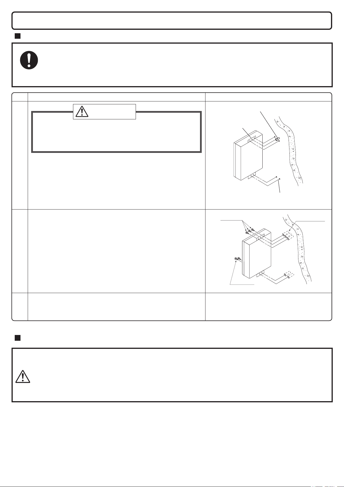
4. Installing the System Controller
Securing to the wall
●
The weight of the device will be applied to the wall. If the strength of the wall is not sufcient, reinforcement
must be done to prevent the transfer of vibration.
●
Do not drop or apply unnecessary force to the device when installing. Internal parts may be damaged and
Be sure to do
may become highly dangerous.
●
Install the unit on a vertical wall and ensure that it is level.
Item
Check
CAUTION
•
When installing with bare hands, take caution to not inict injury.
•
We recommend using gloves.
• Be careful not to hit electrical wiring, gas, or water piping
while drilling holes.
1. Drill a single screw hole, making sure to hit a stud.
2. Insert and tighten the screw and hang the unit by the upper
wall mounting bracket.
Locating Screw Holes
3. Determine and mark the positions for the remaining four
screws (two for the top bracket and two for the bottom), and
remove the unit.
4. Drill holes for the remaining four screws.
Use wall anchors if necessary.
5. Hang the unit again by the rst screw, and then insert and tighten
the remaining four screws.
6. Take waterproong measures so that water does not enter the
Mounting
building from screws mounting the device.
Location of Screw Hole
Mounting Bracket
(upper)
Tapping
Screws
Illustration
Locating Screw Holes
Wall
Anchors
Tapping
Screws
• Make sure the unit is installed securely so that it will not fall or
move due to vibrations or earthquakes.
Structure
Electrical Wiring
CAUTION
This appliance must be electrically grounded in accordance with local codes, or in the absence of local codes, with the National
Electrical Code, ANSI/NFPA 70. In Canada, the latest CSA C22.1 Electrical Code.
Caution: Label all wires prior to disconnection when servicing controls. Wiring errors can cause improper and dangerous
operation.
Verify proper operation after servicing.
Field wiring to be performed at time of appliance installation.
Consult a qualied electrician for the electrical work.
- Do not connect electrical power to all water heaters and system controller (do not turn ON
the power supply) before all electric wiring is completed. Otherwise, electric shock or failure
of the water heater and system controller may occur.
- If a remote controller cord is not connected, the temperature of the water heater is xed to
120°F (50°C) and high-temperature hot water is discharged. So check it is surely connected.
- Be sure to tighten the screw to the terminal block manually and do not use an electric
screwdriver or impact driver. Otherwise, the terminal block may be damaged.
─4─
WARNING
Electrical Shock Hazard
Do not turn power on until electrical wiring is nished. Disconnect power before servicing.
Failure to do so may result in death or serious injury from electrical shock.
• The electrical supply required by the system controller
is 120VAC at 60 Hz.
Use an appropriate circuit.
• For instructions on connecting the power cord, refer to
the “Procedure of connecting the power cord to system
controller” sheet attached in the system controller.
Ground
• To prevent electrical shock, provide a ground with resistance less than 100 .
An electrician should do this work.
Do not connect the ground to the city water or gas piping. Do not tie the ground to a telephone line.
Breaker Installation
• Mount a device which shuts off the electrical path automatically (leakage breaker) when electrical leakage is detected.
• Do not let the power cord contact the gas piping.
Tie the redundant power cord outside the system
controller. Putting the redundant length of cord inside
the system controller may cause electrical interference
and faulty operation.
CAUTION
Electrostatic discharge can affect electronic components. Take precautions to prevent electrostatic discharges from personnel
or hand tools during the system controller installation and servicing to protect the product’s electronic control.
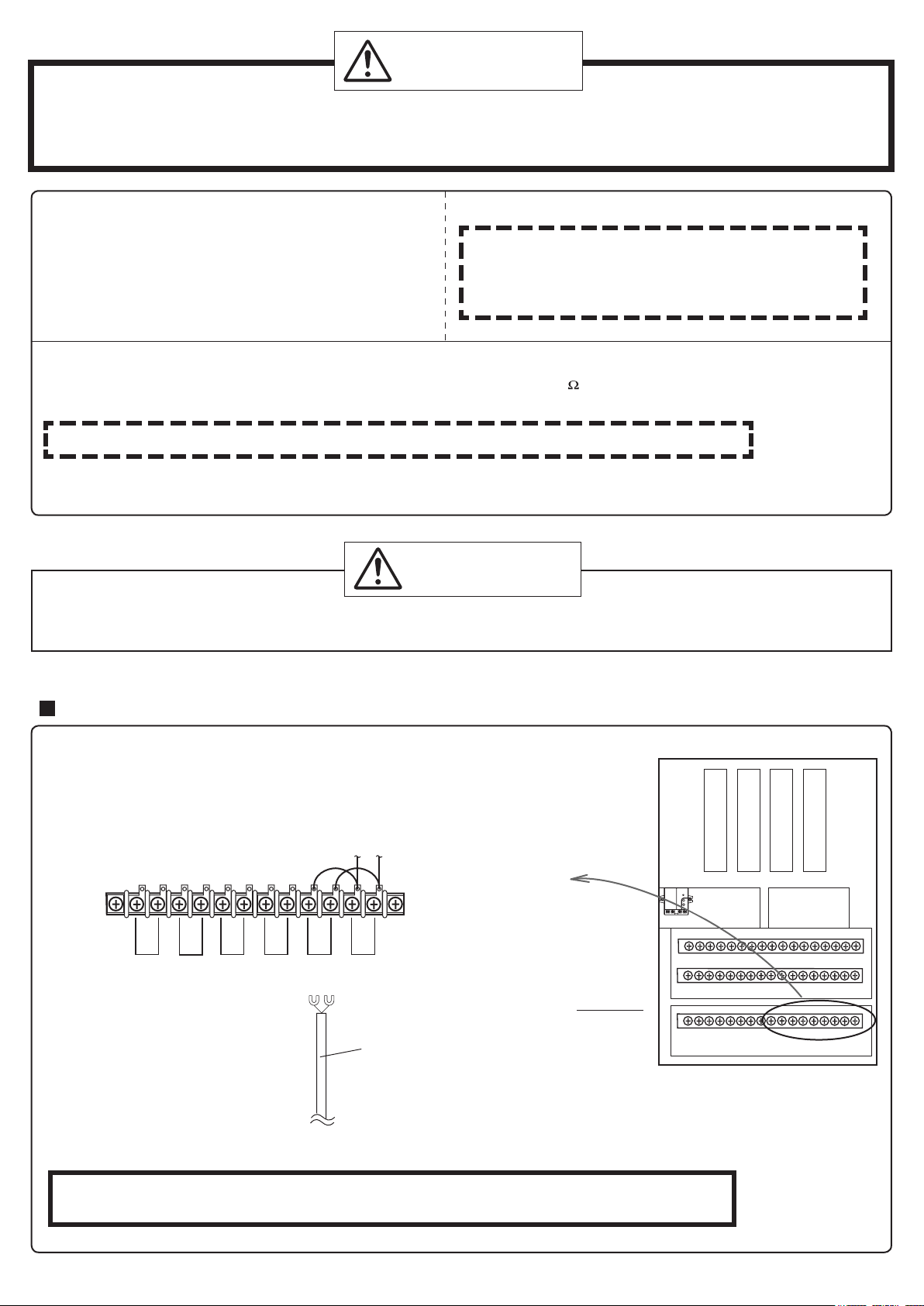
Connection with Remote controller
1. Pass the remote controller cord through one (need to be cut to make a hole) of
the grommets in the base of the system controller. Connect the Y terminals to the
remote controller terminal block as shown below.
2. Install the remote controller as outlined in the water heater installation manual.
Remote
controller 1
Remote Controller Terminal Block
(Inside System Controller)
To remote controller
Connect the communication cord with the remote controller.
Remote
controller 2
* There are two sets of remote controller terminals.
It is okay to connect to one or the other, but not both.
Only one remote controller may be connected.
Remote controller cord
System controller
* Do not connect the communication cord from the units to the remote controller terminal block.
A malfunction will occur.
─5─
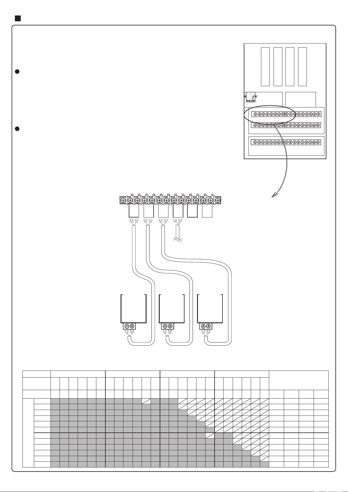
Connection with Water Heater
Connect the communication cords with the water heaters.
Before making wiring connections from each unit to the system controller, make sure that
the electrical power of each unit including the system controller has been disconnected.
1. Remove the front cover from the system controller and the cover of the external remote controller cord terminal block of each water heater.
Connecting the communication cord to Unit 1
2. Using the remote controller cord supplied with the water heater, insert the end with
Y terminals through one (need to be cut to make a hole) of the grommets in the
base of the system controller. Connect the Y terminals to terminal block “01”.
3. Cut off the connector on the other end of the remote controller cord. Attach the Y
terminals in place of the connector.
4. Connect the free end of the remote controller cord to the external remote controller
cord terminal block of Unit 1.
Connecting the communication cord to Units 2-24
5. Connect Units 2-24 in the same way as Unit 1. Be sure to connect the units to the
water heater terminals in the system controller, following the list of connections of
water heaters.
* For the terminal block that is not used, nothing should be done.
* After all connections are made, replace the front cover of the system controller (taking
special care to do not crush any wires) and the covers of the external remote controller
cord terminal blocks of all connected water heaters.
System controller
Slave controller 1
Slave controller 2
Slave controller 3
Slave controller 4
Power
PCB
Group 1
Group 3Group 4
Master
controller
Group 2
01
02 03
04
05
06
Water Heater Terminals (Inside System Controller)
Remote controller cords
Unit 1 Unit 2 Unit 3
Remote controller cord terminal block of each water heater.
List of connections of water heaters
Group No. Group 1 Group 2 Group 3 Group 4
Sub power of
each slave
controller
Water Heater
Terminal No.
13 units 6 units 5 units 2 units 0 unit
Number of Water heaters
14 units 6 units 6 units 2 units 0 unit
15 units 6 units 6 units 3 units 0 unit
16 units 6 units 6 units 4 units 0 unit
17 units 6 units 6 units 5 units 0 unit
18 units 6 units
19 units 6 units
20 units 6 units 6 units 6 units 2 units
21 units 6 units 6 units 6 units 3 units
22 units 6 units 6 units 6 units 4 units
23 units 6 units 6 units 6 units 5 units
24 units 6 units 6 units 6 units 6 units
○ ○ ○ ○
01 02 03 04 05 06 07 08 09 10 11 12 13 14 15 16 17 18 19 20 21 22 23 24
*Connect water heaters at the gray points.
Number of
connected units
Group 1 Group 2 Group 3 Group 4
6 units 6 units 0 unit
6 units 5 units 2 units
─6─
System Controller
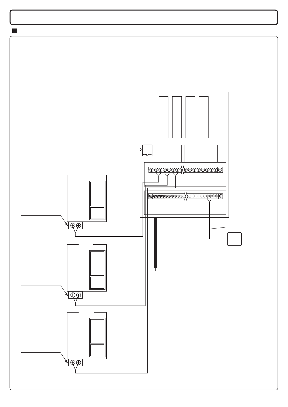
5. Wiring Diagram, System Diagram
Wiring Diagram (Multi-unit System Wiring)
CAUTION
• The below diagram shows the connection of 3 units to the system controller.
When connecting 4 or more units, follow the same procedure.
• Connect the water heaters to the system controller following the detailed wiring instructions
included with the system controller.
• Always connect a remote controller to the system controller.
* The remote controller terminal location
may differ depending on the unit.
Slave controller 1
Slave controller 2
Slave controller 3
Slave controller 4
Remote Controller Cord
terminal block
Remote Controller Cord
terminal block
Unit 1
Unit 2
PCB
Power
PCB
Remote Controller Cord
PCB
Power
PCB
Power
PCB
120VAC, 60Hz
System controller
power supply
* The power cord is not supplied with System controller.
(For procedure of connecting the power cord, refer to “Procedure of connecting
the power cord to System Controller” sheet stuck into the system controller.)
Master
controller
Water heater
Terminals
(Units 1 - 24)
Remote Controller Cord
Remote
Controller
Remote Controller Cord
terminal block
Unit 3
Remote Controller Cord
PCB
Power
PCB
Remote Controller Cord
──
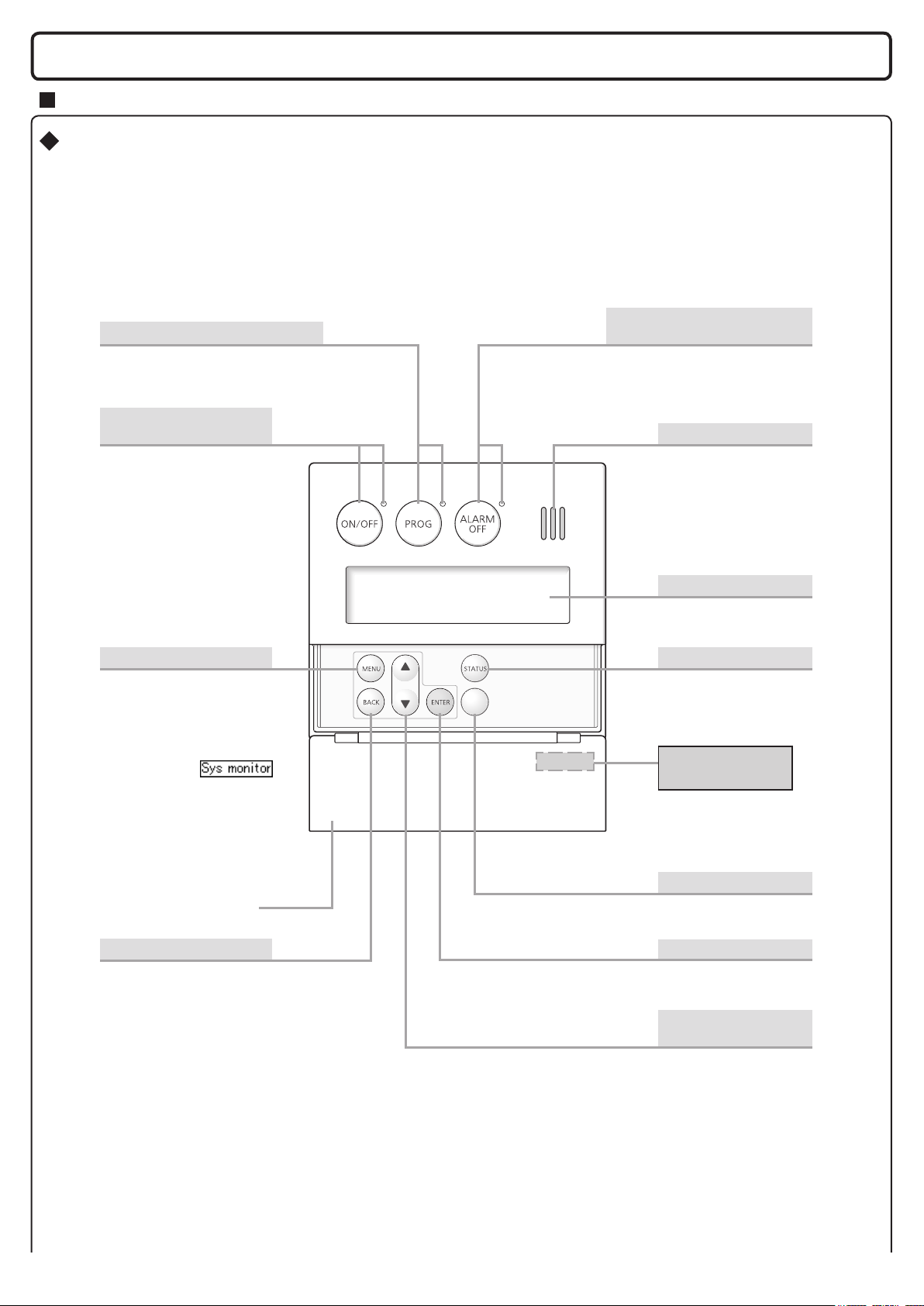
6. Remote button and display overview
Remote Controller (Required Accessories : RC-9018M)
The remote controller will emit a tone when a button is pressed.
*
This Remote Controller is not resistant to water, steam, chemicals, or UV rays. Please install it in a location where it
will not be exposed to these conditions. If it must be installed outdoors, please use a weatherproof enclosure. Consult
the RC-9018M Installation Manual for details.
Alarm Off Button
Prog Button / Indicator (Red)
Activates the automatic water heater power
“ON” or “OFF” setting as determined by the
user selected schedule.
Power ON /OFF Button
/ Indicator (Green)
For turning the water heater
on/off.
Stops the tone that is emitted
when an error occurs.
(page 29.)
/ Indicator (Red)
Speaker
Menu Button
* Use to change system
settings or to return to
the home screen.
*
If you press the menu button
and press the temperature
setting buttons,
is sometimes displayed.
However, do not use this
mode as it is meant
for
installation or service
personnel only.
Cover shown in
the open position.
Back Button
Returns to the previous
screen while making system
settings or checking status.
Display Screen
(Next page)
Status Button
Check the status of the
system or the number of
installed units.
(page 16, 29.)
Remote Controller
Part Number
The part number is
printed on the surface
of the cover.
Lock Button
Locks remote controller
operation.
Conrms changes
made by the user.
Hot Water Temperature
Setting Buttons
For setting the hot water
temperature, and
other settings.
(page 20.)
Enter Button
─8─
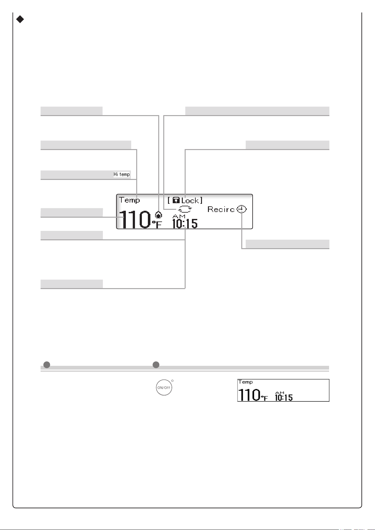
Screen Display
* The screen display shown below is for illustration purposes only.
The actual display will vary depending on how the water heater is being used.
* After a button is pressed, the display will gradually become darker to prevent unnecessary power consumption
by the remote controller.
Flame Symbol
The ame symbol is displayed during
combustion when using hot water or
recirculation functions.
Display for Temperature Setting
During normal operation, the set
temperature is displayed.
Display for High Temperature
Displays when the set temperature
is 125°F/55°C (131°F) or higher.
Temperature Setting
(Ex.: 110°F)
Clock Display
(Ex.: AM10:15)
Normally the clock display is not shown when
the power ON/OFF button is "OFF".
* This setting can be changed so that the clock is displayed
even when the power button is turned "OFF".
Error Code
A number will ash if a
failure occurs. (page 29.)
(page 19.)
*
For systems that use recirculation operation, the symbol
is displayed when the power ON/OFF button is set to "ON".
*
It is displayed during the recirculation operation.
Display for Recirculation Operation
Locked Display
The lock symbol is displayed
when the remote controller is
locked.
The clock symbol is displayed
when the recirculation timer is
activated.
(page 20.)
Recirculation Timer
(page 14 - 15.)
Note: As shipped from the factory, the remote controller is set to display in °F and gallons.
To adjust the display to °C and liters, refer to the
page 13
.
What is the home screen?
The home screen is displayed when the button is "ON".
Normally, the hot water temperature and the clock, etc. are displayed.
<Home Screen Example>
──
 Loading...