

System Controller
*SHA8754 C*
SC-201-6M INT
Installation Manual
Potential dangers from accidents during installation and use are divided into the following two
categories. Closely observe these warnings, they are critical to your safety.
WARNING
NOTICE
Denotes content that may result in fi re, serious bodily injury and even death
when ignored.
Denotes content that may result in bodily injury and physical damage when
ignored.
Requests to Installers
WARNING
Failures and damage caused by erroneous work or work not as instructed in this manual are not
covered by the warranty.
Refer to installation manual attached to the appliance as well.
Check that installation was done in accordance with this Installation Manual upon completion.
After completion of installation, be sure to hand this Installation Manual to the customer.
1.Included Accessories
Part Shape Q'ty Part Shape Q'ty
Installation Manual
(This document)
In order to use this product safely, read this installation manual carefully and
follow the installation instructions.
The following accessories are included with
this product. Check for missing items before
installing.
13
Tapping Screw
4 x 8
System Controller
Mounting Plate
Cord Bushing
*1 Use the vinyl ties for loose electrical wiring inside the unit.
SHA8754-5
Rev. 10/09
*1
Vinyl Tie
1
- 1 -
31
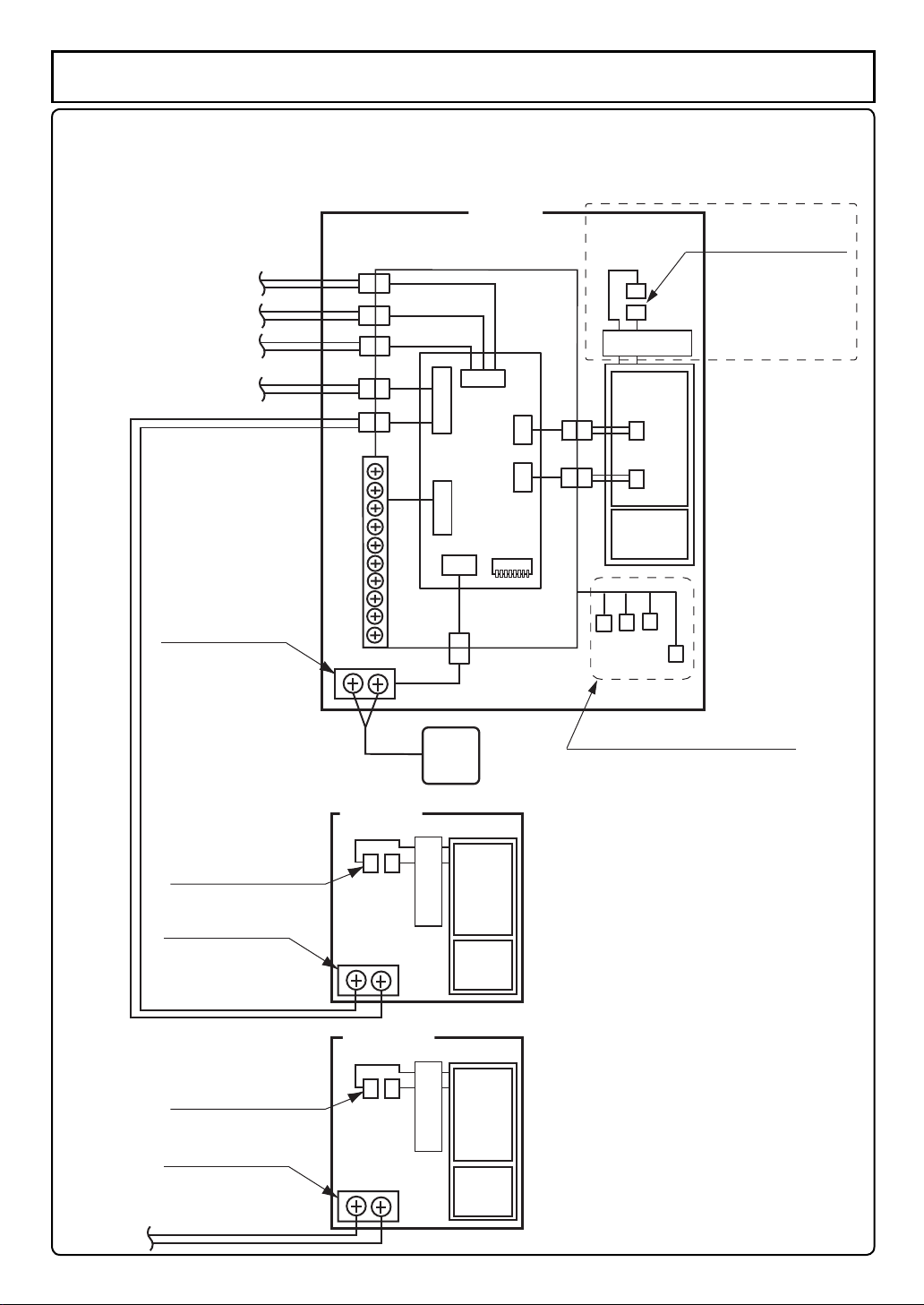
Multi-System Wiring
* Connect these to the
remote control terminal
block in each unit
No.6
No.5
No.4
No.3
No.2
Unit 1
System Controller
DIPSW
12345678
*N-132M(-ASME),N-1321M-ASME, NC380-SV-ASME
N-084M(-DV)(-ASME),N-0841MC(-DV),NCC199-SV(-DV)
N-0842MC(-DV)
NC199-OD(-DVC)
N-0931M(-DV, -OD)(-ASME) ,NC250-SV(-DV)-ASME only
Disconnect this
connector
Disconnect for
system controller
89
90
90
B5
B5
PCB
102
Power
PCB
*Remote control
terminal block
*Disconnect this
connector
Remote control
terminal block
Remote Controller Cord
*Disconnect this
connector
Remote control
terminal block
Remote Controller Cord
Unit 2
Unit 3-6
Remote
Controller
PCB
Disconnect for
system controller
Power
PCB
PCB
Disconnect for
system controller
Power
PCB
System select connectors
* The remote control terminal
location may differ depending on
the unit.
* The connector location may
be slightly different on the
actual circuit board than in
these illustrations.
- 2 -
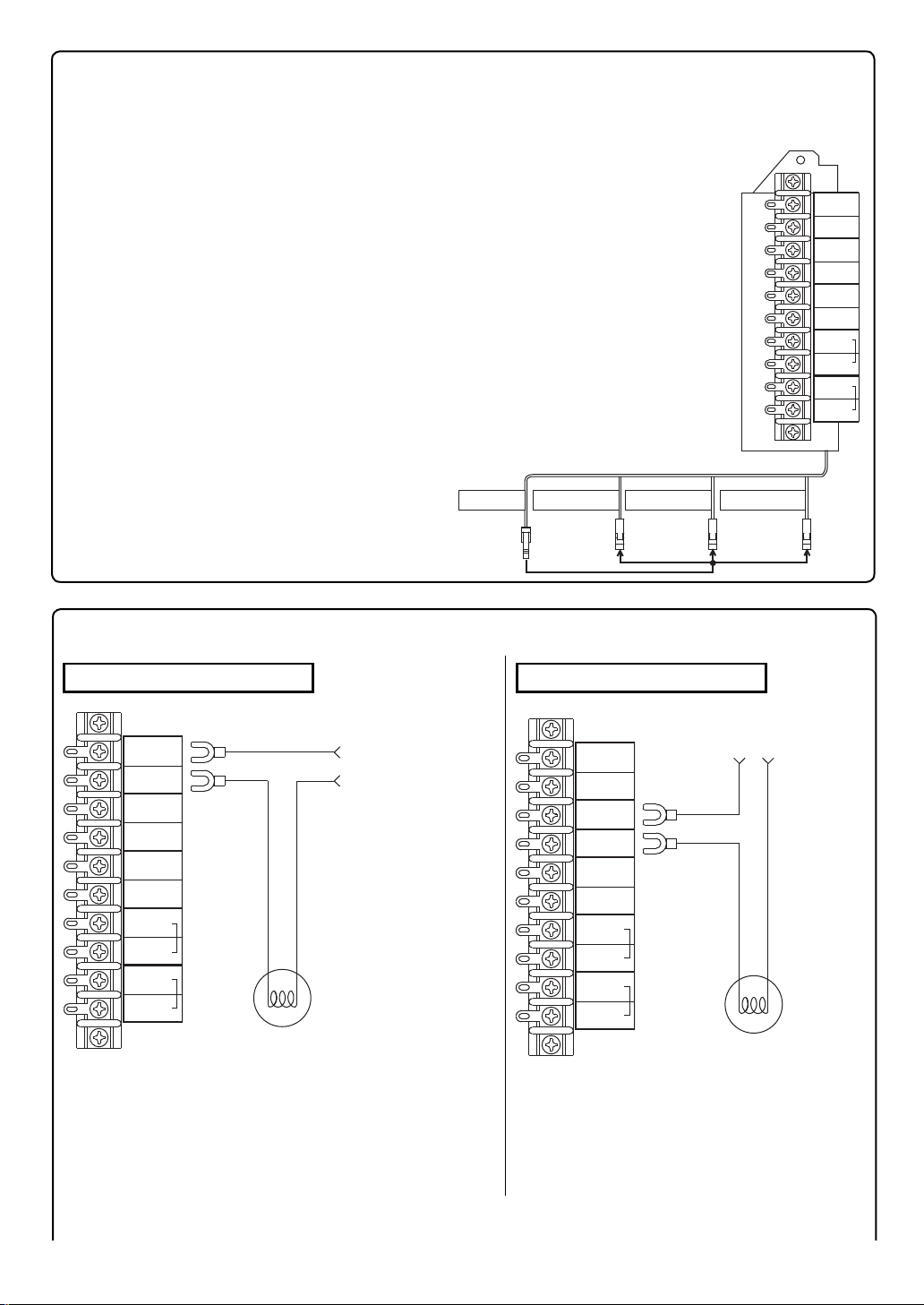
System Select Connectors
M
A
X
100W
Connect to
terminals
AC Power Supply
AC100-240V
Under 100W
Warning Light
1
2
Warning
Light
Warning
Light
Operation
Relay
Operation
Relay
Fan
Fan
Pump
1
Pump
Pump
2
Pump
If this system will be installed with a recirculation system, a storage system,
or with a fi ltration system, plug the selecter in to the connector
that corresponds to that type of system.
*If none of these circulating systems are used, do not connect the selecter.
If the units will be installed in a (1)
recirculation system:
Connect the selecter to the connector
labeled "Recirculation System" (1).
If the units will be installed with a (2)
storage tank:
Connect the selecter to the connector
labeled "Storage System" (2).
If the units will be installed with a water (3)
fi ltration system:
Connect the selecter to the connector
labeled "Filtration System" (3).
Selecter
Filtration System
Storage System
Recirculation
System
Warning
Light
Warning
Light
Operation
Relay
Operation
Relay
Fan
Fan
Pump1
Pump1
Pump2
Pump2
M
100W
A
X
(1)(2)(3)
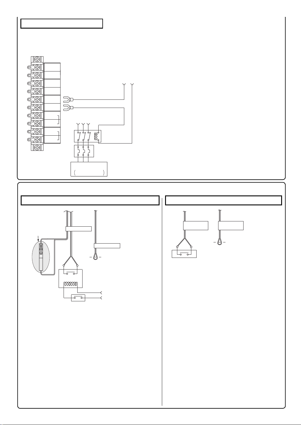
System Controller Terminals (Optional Connections)
Operation LightWarning Light
A warning light can be connected to the system as •
above to warn of any abnormal operation.
When this light fl ashes, check for an error code on
the remote controller and diagnose accordingly.
- 3 -
M
A
X
An operation light can be connected •
to the system controller as above in
order to indicate when power has been
turned on to the system.
Warning
Light
Warning
Light
Operation
Relay
Operation
Relay
Fan
Fan
Pump
Pump
Pump
Pump
100W
AC Power Supply
AC100-240V
Under 100W
Connect to
terminals
1
1
2
2
Operation Light
For connection to
Pump 1, see 1)
←
M
A
X
Circulation Pump
100W
1
2
Operation
Relay
Operation
Relay
Fan
Fan
Pump
1
Pump
Pump
2
Pump
Warning
Light
Warning
Light
Single phase AC120V or
Three phase AC240V pump voltage etc.
Relay
Thermal Relay
AC Power Supply
AC100-240V
Under 100W
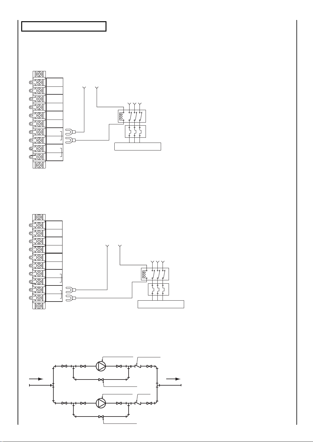
Circulation Pump Terminals
Use these terminals to control the pump in any circulating system.•
Connected this way, the system controller will control the function of the pump.
Use a normally open relay to supply power to the pump. Use a thermal relay if necessary.•
When operating with 1 circulation pump(1)
AC Power Supply
1
1
2
2
AC100-240V
Under 100W
Single phase AC120V or
Three phase AC240V pump voltage etc.
Relay
Thermal Relay
Circulation Pump
Warning
Light
Warning
Light
Operation
Relay
Operation
Relay
Fan
Fan
Pump
Pump
Pump
Pump
M
100W
A
X
*If there is only one pump, connect to "Pump 1" terminals.
If two circulating pumps will be used:(2)
Connect as below if two circulating pumps will be used. The two pumps can be set to alternate
with a dipswitch change. (Refer to the "Dipswitch Settings" section.)
*Do not connect both Pump 1 and Pump 2 to the same terminal block.
* After connecting as shown above, set dipswitch 3 to "OFF".
(Refer to the "Dipswitch Settings" section.)
Piping diagram for parallel pipe installation•
Circulation pump
Flow control valve
Circulation pump
Check valve
Check
value
Adjust the pump fl ow with the fl ow control
valves.
If multiple pumps are used, control the fl ow of
Flow control valve
- 4 -
each pump with separate valves.
Exhaust Fan Terminal
M
A
X
100W
Connect to
terminals
Exhaust Fan
Ventilation Fan
Three phase AC240V etc
Single phase AC120V
Thermal
Relay
1
2
Operation
Relay
Operation
Relay
Fan
Fan
Pump
1
Pump
Pump
2
Pump
Warning
Light
Warning
Light
Relay
AC Power Supply
AC100-240V
Under 100W
These terminals will close when any of the units are heating or when the fan on any of the units is •
blowing. These terminals can be used to control an exhaust fan or damper in this way.
Use a relay to provide power to the fan or damper. Use an additional thermal relay if necessary.•
Pressure Switch/Safety Shutoff Switch and External Operation Switch Connections
Pressure Switch/Safety Shutoff Switch Connection
Please remove
this connector
when Wind Pressure
SW are connected.
A pressure switch or other safety device can be •
installed to shut down the system under unsafe
or improper operation.
Please use a low voltage (15V) junction, normally •
open relay.
This terminal is short circuited at time of •
shipment.
In order to use this feature, cut the wire labeled
"Pressure Switch", connect it to the relay, and
disconnect the connector
Pressure Switch
15V 3.3mA
* Using the Noritz remote
Relay
controller cord, the cord
can be extended to
500m (1500ft.) maximum.
Pressure SW
Pressure Switch
Cut wire
Power Supply
Connecting the external operation switch
External
Operation Switch
External operation SW
External
Operation Switch
Cut wire
15V 3.3mA
* Using the Noritz remote
controller cord, the cord
can be extended to
500m (1500ft.) maximum.
Follow this procedure to use an external •
switch to turn power on and off to the unit
instead of the remote controller.
The power to the units will be on (1)
when the external switch is turned on
(closed).
The power to the units will be off when (2)
the external switch is turned off (open).
Use a low voltage (15V) junction.•
If the units are installed with a recirc *
ulation system,a storage tank or a
fi ltration system, the pump will also turn
on or off with this switch.
- 5 -

Multi-System
A. Installation without a recirculation system
* Do not connect to
* Disconnect this connector
Disconnect this Connector
*N-132M(-ASME),N-1321M-ASME,NC380-SV-ASME
N-084M(-DV)(-ASME),N-0841MC(-DV),NCC199-SV(-DV)
N-0842MC(-DV)
NC199-OD(-DVC)
N-0931M(-DV, -OD)(-ASME),NC250-SV(-DV)-ASME only
System Select Connector
on units 2-6 also.
"Disconnect for system controller" tag
Remote Controller
the connector.
Gas pipe
G
Pipe
Cold Water Supply
(1 1/4"-2")
Unit
No.1
System Controller
Unit No.2
Unit No.6
(1 1/4"-2")
Hot Water Pipe
- 6 -
Insulate or apply heating materials to both the cold water supply piping and the hot water piping to prevent freezing during cold •
weather and to prevent heat loss through the piping.

B-1. Example of Recirculation with a Multi-System
This system will make hot water more quickly available to remote fi xtures.
The pump will circulate water through the loop until the entire loop is warm, and then the system
controller will turn off the pump until the loop cools down.
(1 1/4"-2")
Size the water supply piping to
Water supply
*
allow for maximum flow rates
Gas Pipe
of the units.
G
Circulation Pump 2
(If Necessary)
When installing 2 pumps in parallel
Remote Controller
Circulation Pump 1
* Set dipswitch 3 to "OFF".
(See page of Dipswitch Settings)
Connect to the "Recirculation System"
Disconnect this Connector
* Also disconnect this connector on units 2-6
"Disconnect for system controller" tag
* N-132M(-ASME),N-1321M-ASME,NC380-SV-ASME
N-084M(-DV)(-ASME),N-0841MC(-DV),NCC199-SV(-DV)
N-0842MC(-DV)
N-0931M(-DV, -OD)(-ASME),NC250-SV(-DV)-ASME only
Unit 1
Unit 2
System Controller
connector.
System select connector
Expansion
Tank
(3/4"-1 1/4")
Hot Water Return Line
Size the pump to provide at least 8L/min. (2 GPM) @ 3m (30 kpa (10 feet)) of head + piping *
losses through the system. Turn the power button "ON" and check the maintenance monitors on
the unit to make sure the pump is providing adequate fl ow.
Make sure that the fl ow rate is not greater than 1.2m/sec. (4 ft./sec.).•
(3/4": 20L/min. (5 GPM), 1 1/4": 50L/min. (13 GPM))
If the fl ow is too low, the recirculation loop temperature will not be warm enough, if the fl ow is too
high, the lifetime of the unit will be reduced.
If there are multiple circulation loops, try to make the fl ow rate 3 - 5L/min. (.75 - 1.25 GPM) in *
each loop.
Use copper or stainless water piping for the entire system.*
(1 1/4"-2")
Unit 6
Hot Water
Hot Water
Supply
- 7 -

B-2. Example of Installation with a Storage Tank and Recirculation System
The pump will push water through the Multi-System to heat up the tank.
When the return temperature is high, the fl ow within the device will be limited to 10L/min. (2.6 GPM)*.
(For the 84M, the fl ow will be limited to 1.3 GPM.)
(For the KM3211WH and (L)WH(X)56, the fl ow will be limited to 5L/min.)
Hot WaterSupply
Return line
circulation pump
Hot water supply line
(Copper or Stainless Pipe)
(Copper or Stainless Pipe)
* If the tank thermostat will control the pump,
set dipswitch 2 to OFF. (See page of Dipswitch Settings)
Do not connect more than one pump to the tank thermostat.
Thermostat
Relief Valve
Hot water return line
F).
°
Hot Water
Storage Tank
G
Gas Pipe
* Set dipswitch 3 to OFF.
(See page of Dipswitch Settings)
Option 1-Tank
Remote
Controller
Thermostat Control
Option 2-Unit
Control
Pump Control
Wires (use an
external relay,
see page 4)
(if Necessary)
Storage Tank Circulation Pump 2
The system controller will stop the units from heating when the tank is up to temperature,
and the unit will cut the flow through it to 10L/min. (2.6 GPM.)
(For 84M, the flow is limited to 1.3 GPM.)
(For KM3211WH and (L)WH(X)56, the flow is limited to 5L/min.)
When installing 2 pumps in parallel
Install the plumbing so that a change in flow will not damage the pump.
disconnect this
System select connector
Connect to the “Sto-
rage system”
"Disconnect for system
Controller" tag
connector on units 2-6
* Also
connector"
Disconnect this Connector
* N-132M(-ASME),N-1321M-ASME,NC380-SV-ASME
N-084M(-DV)(-ASME),N-0841MC(-DV),NCC199-SV(-DV)
N-0842MC(-DV)
N-0931M(-DV, -OD)(-ASME),NC250-SV(-DV)-ASME only
Cold Water Supply
* Size the water supply piping to
allow for maximum flow rates
of the building.
Storage Tank Circulation Pump 1
C (10
°
C or more, the dipswitch 4 is turned to OFF.
°
System Controller
Unit 6 Unit 2 Unit 1
(1 1/4"-2")
Storage tank return line
(Copper or Stainless Pipe)
- 8 -
(1 1/4"-2")
Storage tank supply line
(Copper or Stainless Pipe)
To achieve the highest recovery, size the storage tank circulation pump for maximum capacity. *
All USA MODELS : Refer to the Installation Manual provided with the water heater for sizing guidelines.
(L)WH(X)56, (L)WHC56, KM3211WH, BC3200RA : 32L/min. (each) @ 12 m of head + piping losses through the system.
Except USA model. (See page of Dipswitch setting.)
For the set temperature of the remote control, use the set temperature (of the thermostat) + about 6 *
When the recirculation loop set temperature is adjusted to 65 *
Verify that the supply pressure to the units is at least 0.2MPa (2 bar).

2.
Gas Piping
Follow the instructions from the gas supplier.
Gas Connection
Gas fl ex lines are not recommended unless•
they are sized for the maximum input
kW (Btu/h
Do not use piping with a diameter smaller than •
the size of the gas inlet to each unit.
After installation, check the gas line for any •
leaks before using.
3.Water Piping
The plumbing should be installed by a qualifi ed plumbing contractor according to all applicable •
codes and regulations.
Insulate or apply heating materials to the supply and hot water piping to prevent freezing during •
cold weather and to prevent heat loss through the piping.
Use a union coupling or fl exible pipe for connecting the units to ease service and maintenance.•
Refer to the system diagrams for supply and hot water pipe sizing. Do not install piping that is •
smaller than the inlet or outlet water connections on the units.
•
MJ) of each unit.
Ask a qualifi ed plumber to perform the installation. Observe all
applicable codes.
Gas Valve
Install a gas shutoff valve for every unit
installed.
Gas Meter
Select a gas meter capable of supplyingthe
entire kW (Btu/h
appliances that the meter serves. Size the gas
line for the entire kW (Btu/h
•
MJ) demand of all gas
•
MJ) demand also.
If using an expansion tank, make sure it is correctly sized for the system.•
Use only copper or stainless steel pipe for all plumbing.•
Keep the plumbing as simple as possible.•
Avoid using pipes in which air can accumulate.•
Use only approved materials, and have the installation inspected upon completion.*
- 9 -

Electrical Wiring4.
Do not connect electrical power to the unit until all electrical wiring has been completed.•
NOTICE
N-132M(-ASME), N-1321M-ASME, NC380-SV-ASME
When installing the system controller, take care not to damage the internal electrical components in the (1)
unit and tie off loose electrical cords with the included vinyl ties.**
Remove the connector from the circuit board to the remote controller terminal block in the unit.(2)
Connect this disconnected connector labeled 90 from the circuit board to the connector labeled 90
from the system controller.
Connect the connector from the remote controller terminal block to the connector from the system (3)
controller labeled “To remote controller terminal ”.
Connect the B5 connector from the system controller to the B5 connector of the unit.(4)
Use the remote controller cords and the cords included with the system controller to(5)
connect the system controller to the other units.
Unit 1 (The unit with the System Controller)
* The remote controller cord can be extended up to 100m (300 ft.).
Fix with accessory screw
If the remote controller is not connected to the system, the unit will default to • a
60 °C (140 °F) temperature setting.
System Controller
Connect to the connector No.90 of the unit.
Ground Wire
Connect with
accessory screw
Slide system contoroller
into the bracken in the
back of the case.
"To remote controller terminal "
tag
Connector color: red
No.2
Connector color: red
Clamp
* Remote Controller cord
(To a remote controller)
PCB
9090
B5B5
Remote Controller Cord
Connect to the connector
B5 of the unit.
"SYSTEM CONTROLLER" tag
"
Disconnect for system controller
Disconnect this Connector
Disconnect this connector
on units 2-6 also.
"To Gas Water Heater for Multi" tag
" tag
**Note: If remote controller RC-7647M or RC-7650M ( °C temperature display) is being used, an
adjustment to all water heaters connected to the system controller will be necessary.
Make this adjustment prior to making the electrical connections to the system controller.
Refer to page 14 for instructions.
Units 2-6
(Connect each unit to corresponding wires labeled 2-6 from the system controller)
Remote Controller Cord
No.2 To Unit 2
Clamp
No.6 To Unit 6
When installing 2 or more units
Install one remote controller cord for every unit connected to the system controller. Wire each unit
independently to the system controller keeping the overall length of the remote controller cord less
than 15m(45 ft.).
- 10 -

N-084M(-DV)(-ASME), KM3211WH, (L)WH(X)56
When installing the system controller, take care not to damage the internal electrical components in(1) the
unit and tie off loose electrical cords with the included vinyl ties.**
Remove the connector from the circuit board to the remote controller terminal block in the unit.(2)
Connect this disconnected connector labeled 90 from the circuit board to the connector labeled 90
from the system controller.
Connect the connector from the remote controller terminal block to the connector from the system (3)
controller labeled "To remote controller terminal ".
Connect the B5 connector from the system controller to the B5 connector of the unit.(4)
Use the remote controller cords and the cords included with the system controller to connect the (5)
other units to the system controller.
Unit 1
(The Unit with the System Controller)
The remote controller cord length*
When using one remote controller = Maximum length 100m (300ft.).
When using two remote controllers = within 50m (150ft.) each (KM3211WH only).
When using three remote controllers = within 20m (65ft.) each (KM3211WH only).
Please refer to the installation manual of the unit about version and quantity of remote controllers *
that can be connected.
Fix with accessory screw
Ground Wire
Connect with
accessory screw
Fix with accessory screw
System controller
Mounting Plate
Slide system controller
into the bracket in the
back of the case.
"To Gas Water Heater for Multi" tag
"To remote controller terminal " tag
System Controller
Connector color: red
Remote Controller Cord
Connect to the connector No.90 of the unit.
PCB
9090
No.2
Connector color: red
B5B5
Clamp
* Remote Controller cord
(To remote controller)
Connect to the connector
B5 of the unit.
"
Disconnect for system controller
Disconnect this Connector
Disconnect this connector
on units 2-6 also.
*N-084M(-DV)(-ASME) only
" tag
**Note: If remote controller RC-7647M or RC-7650M ( °C temperature display) is being used, an
adjustment to all water heaters connected to the system controller will be necessary.
Make this adjustment prior to making the electrical connections to the system controller.
Refer to page 14 for instructions.
Units 2-6
(Connect each unit to corresponding wires labeled 2-6 from the system controller)
Remote Controller Cord
No.2 To Unit 2
No.6 To Unit 6
Clamp
When installing 2 or more units
Install one remote controller cord for every unit connected to the system controller. Wire each unit
independently to the system controller keeping the overall length of the remote controller cord less
than 15m(45 ft.).
- 11 -

N-0931M(-DV, -OD)(-ASME), NC250-SV(-DV)-ASME
N-0841MC(-DV), NCC199-SV(-DV), N-0842MC(-DV), (L)WHC56, BC3200RA
When installing the system controller, take care not to damage the internal electrical components (1)
in the unit and tie off loose electrical cords with the included vinyl ties.**
Remove the connector from the circuit board to the remote controller terminal block in the unit.(2)
Connect this disconnected connector labeled 90 from the circuit board to the connector labeled 90
from the system controller.
Connect the connector from the remote controller terminal block to the connector from the system (3)
controller labeled "To remote controller terminal ".
Connect the B5 connector from the system controller to the B5 connector of the unit.(4)
Use the remote controller cords and the cords included with the system controller to connect the (5)
other units to the system controller.
Unit 1
(The Unit with the System Controller)
The remote controller cord length*
When using one remote controller = Maximum length 100m (300ft.).
When using two remote controllers = within 50m (150ft.) each (BC3200RA only).
When using three remote controllers = within 20m (65ft.) each (BC3200RA only).
Please refer to the installation manual of the unit about version and quantity of remote controllers *
that can be connected.
Fix with accessory screw
Ground Wire
Connect with
accessory screw
Slide system controller
into the bracket in the
back of the case.
"To Gas Water Heater for Multi " tag
"To remote controller terminal " tag
System Controller
Connector color: red
No.2
Connector color: red
Remote Controller Cord
Connect to the connector No.90 of the unit.
Connect to the connector
PCB
9090
B5B5
* Remote Controller cord
(To remote controller)
B5 of the unit.
"
Disconnect for system controller
Disconnect this Connector
Disconnect this connector
on units 2-6 also.
Except (L)WHC56, BC3200RA
"SYSTEM CONTROLLER" tag
Clamp
" tag
**Note: If remote controller RC-7647M or RC-7650M ( °C temperature display) is being used, an
adjustment to all water heaters connected to the system controller will be necessary.
Make this adjustment prior to making the electrical connections to the system controller.
Refer to page 14 for instructions.
Units 2-6
(Connect each unit to corresponding wires labeled 2-6 from the system controller)
Remote Controller Cord
No.2 To Unit 2
No.6 To Unit 6
Clamp
The location of the terminals will either be inside the unit or external to the unit.*
When installing 2 or more units
Install one remote controller cord for every unit connected to the system controller. Wire each unit
independently to the system controller keeping the overall length of the remote controller cord less
than 15m(45 ft.).
- 12 -

The installer should test operate the system, explain to the
5. T rial Operation
Connect electrical power to each of the units.(1)
Open the gas shutoff valve, the main water valve, and the water shutoff valves on all of the units.(2)
Turn the power ON with the remote controller. (The Operation Lamp will light up.)(3)
Slowly open a hot water fi xture and confi rm that the units ignite in sequence and that the Burner (4)
On Lamp on the remote controller lights.
If an "11" or "12" error code fl ashes on the remote controller, there may be air in the gas line.•
Hit the Power Button ON and OFF a few times and then open the fi xture again to try igniting the
unit again.
If this fi xture does not cause all of the units to ignite, test the rest of the units by switching which •
the primary unit by pressing either the Maximum or Minimum Manifold Pressure Set Button on the
circuit board of the unit.
Operate all of the units and confi rm that the water temperature corresponds to the temperature set •
on the remote controller. Set the remote to the lowest temperature to maximize water fl ow.
If the water temperature is hotter than the set temperature, check to make sure that the remote is
connected to the system controller, and that the system controller is connected to the other units.
If the units do not operate properly, refer to the Troubleshooting section of the Owner's Manual.•
After the test operation, clean any debris off of the fi lter on the water inlet.*
customer how to use the units, and give the owner the Installation
and Operation Manual before leaving the installation.
Checking Water Flow (Maintenance Monitors) Necessary only for recirculation systems
is
N-084M(-DV)(-ASME), N-132M(-ASME), N-1321M-ASME, NC380-SV-ASME, N-0931M(-DV,-OD)(-ASME),
NC250-SV(-DV)-ASME, N-0841MC(-DV), NCC199-SV(-DV), N-0842MC(-DV)
Turn the Power button "ON".(1)
Press the temperature up and down buttons (2) △ and ▽
simultaneously for more than 2 seconds.
(The remote control will display the maintenance monitors.)
"Unit No.", "Data No." and "Data" are displayed on the remote *
controller temperature display.
Press the "FLOW METER ALARM SET" button to change (3)
which unit's information in being displayed.
(The combustion lamp of the selected unit will fl ash twice.)
When switching "Unit No.", the display will change from *
"5C→01→Data No."→"01→02→Data No."→"02→03 →
Data No."• • •"(Last Unit)No.→5C→OFF" when the "FLOW
METER ALARM SET" button is pressed.
If the "FLOW METER ALARM SET" button is not pushed to
change the Unit No., the Data No. for that Unit will then be
displayed on the remote controller.
Press the temperature up or down buttons (4) △ or ▽ to select
Data No.14. The water fl ow through that heater will be
displayed.
Repeat (2) - (3) for all water heaters. Adjust so that the total (5)
water fl ow of all devices is 2 GPM or more.
Press the temperature up and down buttons (6) △ and ▽
simultaneously for over 2 sec. to return to the temperature
display.
Temperature display
Flow Meter Alarm
Set Button
Temperature switch
(Changing the Data No.)
(Device No., Data No., Data)
Power Button
(Device No.)
- 13 -

Checking Water Flow (Maintenance Monitors)
(L)WH(X)56, (L)WHC56, KM3211WH, BC3200RA
Necessary only for recirculation systems
Power On/Off Button
Display
Set Button
Speaker
The Power On/Off Button can be set to either "ON" or "OFF" unit operation will not be affected by this setting.
However, be sure to set the Power On/Off Button to “ON” after turning on the power.
<Display procedure>
Press and hold both the up [(1) ▲] and down [▼] select buttons simultaneously for more than fi ve seconds.
“Maintenance Monitor” display will appear along with the data no. and data.(2)
Displaying data and switching data no.(3)
Press the up [a) ▲] select button to switch display to the next item no. Press the down [▼] set button to
switch display to the previous data no.
Press the set button to switch to the mode for changing the ten’s digit. Use the select buttonsb)
[▲] and [▼] in the same manner as 1) to make changes.
When pressing the setting button again:c)
If the data no. is 03, the microcomputer name of the remote controller is displayed. When the set •
button is pressed again, the unit will return to the mode of 1).
If the data no. is other than 03, the unit will return to the mode of 1).•
During maintenance monitors are displaying, the hot water temperature and other settings cannot be
adjusted.
Press the temperature up or down buttons [(4) ▲] or [▼] to select Data No.14. The water fl ow through that
heater will be displayed.
Repeat (3) - (4) for all water heaters. Adjust (so that) the total water fl ow of all devices is 8L/min. or more.(5)
<Returning to Normal Mode>
For releasing the indication, press and hold both up [(1) ▲] and down [▼] of select buttons simultaneously more
than two seconds, or leave it alone for more than 10 minutes.
Selection Button
Display No. and Unit No.
Display Unit No.
5C SC-201
01 Unit 1
02 Unit 2
•
•
•
06 Unit 6
•
•
•
Water Heater Dipswitch Settings (When using remote controller RC-7647M or RC-7650M)
N-084M(-DV)(-ASME), N-132M(-ASME), NC380-SV-ASME, N-1321M-ASME, N-0931M(-DV,-OD)(-ASME),
NC250-SV(-DV)-ASME, N-0841MC(-DV),NCC199-SV(-DV), N-0842MC(-DV), NC199-OD(-DVC)
When using remote controller RC-7647M or RC-7650M ( °C temperature display), a dipswitch change will be
necessary on all water heaters connected to the system controller. Refer to the below instructions to make the
adjustment. A remote controller will need to be connected to the water heater being adjusted.
Connect electrical power to the water heater and wait 10 seconds before proceeding to step 2.(1)
Within the fi rst ten minutes of connecting electrical power, before turning on the operation button, hit the [(2) ▲]
or [▼] button on the remote controller and hold until the display blinks "99". If "99" does not blink on the
remote controller, unplug the water heater and try again.
Use the [(3) ▲] or [▼] button on the remote controller to scroll to the appropriate dipswitch number as indicated
below.
Press the "FLOW METER ALARM SET" button for 0.5 sec to change the setting ON/OFF:(4)
ON: "priority" lamp fl ashes.
OFF: "priority" lamp goes off.
For models N-084M(-DV)(-ASME), N-132M(-ASME), N-1321M-ASME, NC380-SV-ASME:(5)
Change "A8" from OFF to ON. Do not adjust any other dipswitches!
For models
Change "2F" from OFF to ON. Do not adjust any other dipswitches!
When the dipswitch has been adjusted, confi rm the setting by pressing and holding both the [(6) ▲] and [▼]
buttons on the remote controller until the controller emits a beeping noise. The new setting will be lost if this
is not done.
Repeat this entire procedure for every water heater that will be connected to the system controller.(7)
N-0931M(-DV,-OD)(-ASME), N-0841MC(-DV), NC250-SV(-DV)-ASME, NCC199-SV(-DV), NC199-OD(-DVC):
- 14 -

Dipswitch Settings
N-084M(-DV)(-ASME), N-132M(-ASME), N-1321M-ASME, NC380-SV-ASME, N-0931M(-DV,-OD)(-ASME),
NC250-SV(-DV), N-0841MC(-DV), NCC199-SV(-DV), N-0842MC(-DV)
Disconnect the power to the units before changing the dipswitches.
(Otherwise, settings will not take effect.)
Dipswitch SW8SW7SW6SW5SW4SW3SW2SW1
Pump
abnormality
detection
Pump
rotation
NoYes
YesNo
Set temperature
* All dipswitches are set to ON from the factory.
SW2: Pump abnormality detection
Set to OFF if the pump will not be connected to the system controller, but instead the pump will
be controlled by an external control device.
SW3: Pump rotation
Set to OFF if using 2 pumps.
SW4: If the switch is set to OFF, and the Power Button is turned OFF and ON, the unit will accept
°
125
F return water (if the unit is set at that temperature or higher).
When the dipswitch is ON, the unit will allow the standard return temperature.
* Do not change any other dipswitches.
OFF
ON
1 2345678
- 15 -

Dipswitch Settings
(L)WH(X)56, (L)WHC56, KM3211WH, BC3200RA
Disconnect the power to the units before changing the dipswitches.
(Otherwise, settings will not take effect.)
Dipswitch SW8SW7SW6SW5SW4SW3SW2SW1
Pump
abnormality
detection
Pump
rotation
60 C recovery
during
hightemperature
setting
Power Button
works with
circulation
Yes
No
YesNo
Set temperature Independence
Interlock
* All dipswitches are set to ON from the factory.
SW2: Pump abnormality detection
Set to OFF if the pump will not be connected to the system controller, but instead the pump will
be controlled by an external control device.
SW3: Pump rotation
Set to OFF if using 2 pumps.
SW4: The setting temperature which the Power Button is turned ON, and OFF when the setting is
high temperature.
When the setting temperature is changed above 60°C, turn the Power Button OFF once, then
60°C is displayed when turning the Power Button ON again. (When the dipswitch is ON.)
When the dipswitch is switched to OFF, the temperature will remain at the previous setting.
(before the Power Button is turned to ON.)
SW5: Behavior when turning on the Power Button with remote controller or external operation
terminal.
When the dipswitch is set to ON, the Power Button and the circulation switch are turned ON at
the same time.
When the dipswitch is turned to OFF, only the Power Button is turned to ON.
* Do not change any other dipswitches.
OFF
ON
1 2345678
- 16 -
 Loading...