

Noritz NRC98-OD, NRC83-OD Installation Manual
Potential dangers from accidents during installation and use are divided into the following three
categories. Closely observe these warnings, they are critical to your safety.
Prohibited
Disconnect
Power
Ground
Be sure to do
WARNING:
If the information in this manual is not followed exactly, a re or explosion may result
causing property damage, personal injury or death.
NORITZ AMERICA
CORPORATION
Installation Manual
CONDENSING TANKLESS GAS WATER HEATER
NRC98-OD
(Outdoor Installation)
NRC83-OD
DANGER indicates an imminently hazardous situation which,
if not avoided, will result in death or serious injury.
WARNING indicates a potentially hazardous situation which,
if not avoided, could result in death or serious injury.
CAUTION indicates a potentially hazardous situation which,
if not avoided, may result in minor or moderate injury.
DANGER
WARNING
CAUTION
SBA8677-2
Rev. 03/13
Requests to Installers
• In order to use the water heater safely, read this installation manual carefully, and follow the installation instructions.
• Failures and damage caused by erroneous work or work not as instructed in this manual are not
covered by the warranty.
• Check that the installation was done properly in accordance with this Installation Manual upon
completion.
•
After completing installation, please either place this Installation Manual in a plastic pouch and
attach it to the side of the water heater (or the inside of the pipe cover or recess box if applicable),
or hand it to the customer to retain for future reference. Also, be sure to ll in all of the required
items on the warranty and to hand the warranty to the customer along with the Owner's Guide.
CAUTION
FOR USE IN RESIDENTIAL APPLICATIONS.
I
nstallation must conform with local codes, or in the absence of local codes, the
National Fuel Gas Code, ANSI Z223.1/NFPA 54- latest edition and/or CSA B149.1,
Natural Gas and Propane Installation Code (NSCNGPIC).
Noritz America reserves the right to discontinue, or change at any time, the
designs and/or specications of its products without notice.
CERTIFIED
R
*SBA8677*
Low NOx
Approved by
SCAQMD
14 ng/J or 20 ppm
(Natural Gas Only)

2
1.
Included Accessories
The following accessories are included with the unit.
Check for any missing items before starting installation.
Q’ty
ShapePart
1
each
Part Shape
Q’ty
3
1
Remote Controller
(See p. 19)
Remote Controller
Cord (6ft (2m))
1
2.
Optional Accessories
The accessories listed below are not
included with the units, but may be necessary
for installation.
Cross Recessed
Head Screw
Quick Connect Cord
(QC-2)
Q’ty
ShapePartPart Shape
Q’ty
1
1
Remote Controller
Cord (26ft (8m))
1
Isolation V alves
(includes pressure
relief valve)
Pipe Cover
(PC-3S)
1
1
Recess Box
(RB-900)
1
Remote Controller
Outdoor
Junction Box
Owner's Guide, Warranty,
Installation Manual
(this document)
3
G
Quick Connect
Cord
Remote Controller Cord
Gas Supply Piping
Cold Water Supply
Hot Water
Remote Controller
Terminal Block
Cord
Connector
Cord
Connector
3.
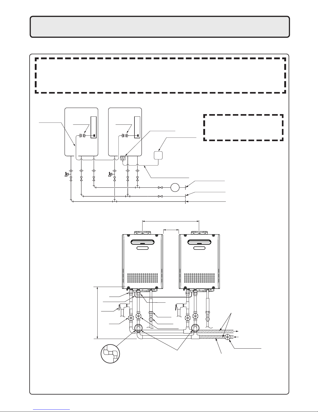
Quick Connect Multi System Installation
• The Quick Connect Multi System allows the installation of two units together utilizing only the Quick
Connect Cord.
Typical Plumbing
* When connecting two units, use only a
single remote controller.
Note: Connect the remote
controller to only one
of the units.
System Diagram
• Insulate the hot water piping to prevent heat loss. Insulate and apply heating materials to the
cold water supply piping to prevent heat loss and freezing of pipes when exposed to excessively
cold temperatures.
Union
Make this distance as short as possible.
* The hot water temperature will
become unstable as the pipe
length increases.
Quick Connect
cord
Union
Gas Valve
Union
Shutoff
Valve
Shutoff Valve
Hot Water
Cold Water
Leave enough clearance around the plumbing to
apply insulation. It will be necessary to add
bends to the piping to ensure that this clearance
is available.
Pressure
Relief
Valve
Shutoff Valve
Size the piping to allow for the
maximum flow rates of the units.
The backflow preventer is
put up before it diverges.
Distance at center: 20.3 - 36.3 in. (515 - 922mm)
Distance on sides
2 - 18 in. (50 - 457mm)
The Quick Connect Cord is 6 ft.(2m) long. Install the units 2-18" (50 - 457mm) apart from each
other to ensure the cord will be able to reach between the units. (See Typical Plumbing diagram).
(If the distance between the two units is too great, not only will the cord not be able to reach,
but the water temperature may also become unstable because of the difference in pipe length
between the two units).
4
Check the Gas
• Check that the rating plate indicates the
correct type of gas.
• Check that the gas supply line is sized for
180,000 Btuh for NRC98-OD, 157,000 Btuh
for NRC83-OD.
Check the Power
• The power supply required is 120VAC, at 60Hz.
May result in re or electric shock.
Use Extreme Caution if Using With a Solar Pre-Heater
• Using this unit with a solar pre-heater can lead to unpredictable output temperatures and
possibly scalding. If absolutely necessary, use mixing valves to ensure output temperatures do
not get to scalding levels. Do not use a solar pre-heater with the quick-connect multi-system.
4.
Before Installation
Do Not Use Equipment for Purposes Other Than Those Specied
• Do not use for other than increasing the temperature of the water supply, as unexpected accidents
may occur as a result.
Check Water Supply Quality
• If the water supply is in excess of 12 grains per gallon (200 mg/L) of hardness, acidic or otherwise
impure, treat the water with approved methods in order to ensure full warranty coverage.
WARNING
CAUTION
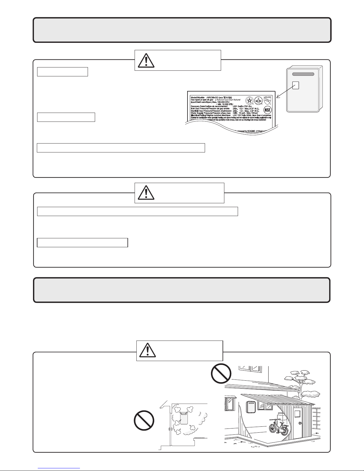
5.
Choosing Installation Site
* Locate the appliance in an area where leakage from the unit or connections will not result in damage
to the area adjacent to the appliance or to the lower oors of the structure. When such locations can-
not be avoided, it is recommended that a suitable drain pan, adequately drained, be installed under
the appliance. The pan must not restrict combustion air ow.
DANGER
Indoor
• This water heater is for outdoor installation only.
Never install it indoors.
Do not enclose the termination with corrugated
metal or other materials.
This will cause carbon monoxide
poisoning and a potential re
hazard.
5
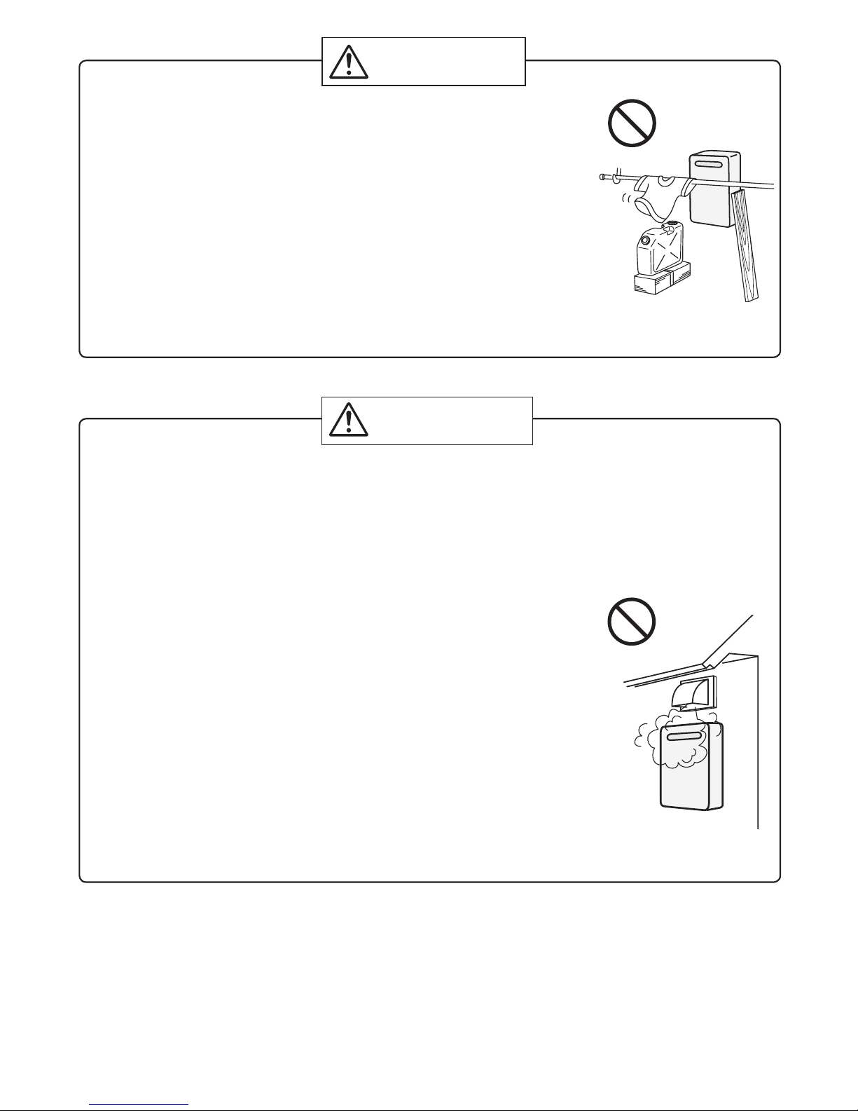
• Avoid places where res are common, such as those where gasoline,
benzene and adhesives are handled, or places in which corrosive gases
(ammonia, chlorine, sulfur, ethylene compounds, acids) are present.
Using the incorrect voltage may result in re or cracking.
• Avoid installation in places where dust or debris will accumulate.
Dust may block the air-supply opening, causing the performance of the
device fan to drop and incomplete combustion to occur as a result.
• Avoid installation in places where special chemical agents
(e.g., hair spray or spray detergent) are used.
Ignition failures and malfunction may occur as a result.
• Carbon Monoxide Poisoning Hazard. Do not install this water heater in a
mobile home, recreational vehicle or on a boat.
• Install the water heater in a location where it is free from obstacles and
stagnant air.
• Consult with the customer concerning the location of installation.
• Do not install the water heater near staircases or emergency exits.
• Do not install the water heater where the exhaust will blow on outer walls
or material not resistant to heat. Also consider the surrounding trees and
animals.
The heat and moisture from the water heater may cause discoloration of
walls and resinous materials, or corrosion of aluminum materials.
• Do not locate the vent termination directed towards a window or any
other structure which has glass or wired glass facing the termination.
• Install in a location where the exhaust gas ow will not be affected by
fans or range hoods.
• Take care that noise and exhaust gas will not affect neighbors.
Avoid installation on common walls as the unit will make some operational noises while it is running.
• Avoid installation where the unit will be exposed to excessive winds.
• Before installing, make sure that the vent termination will have the proper
clearances according to the National Fuel Gas Code (ANSI Z223.1).
Prohibited
WARNING
CAUTION
Prohibited
State of California: The water heater must be braced, anchored or strapped to avoid moving during an
earthquake. Contact local utilities for code requirements in your area or call: 1-866-766-7489 and request instructions.
The Commonwealth of Massachusetts:
1) The outdoor units (OD) can only be used if they are for summer use only.
2) The water heater can be used for hot water only and not in a combination of domestic and space
heating.
6
6.
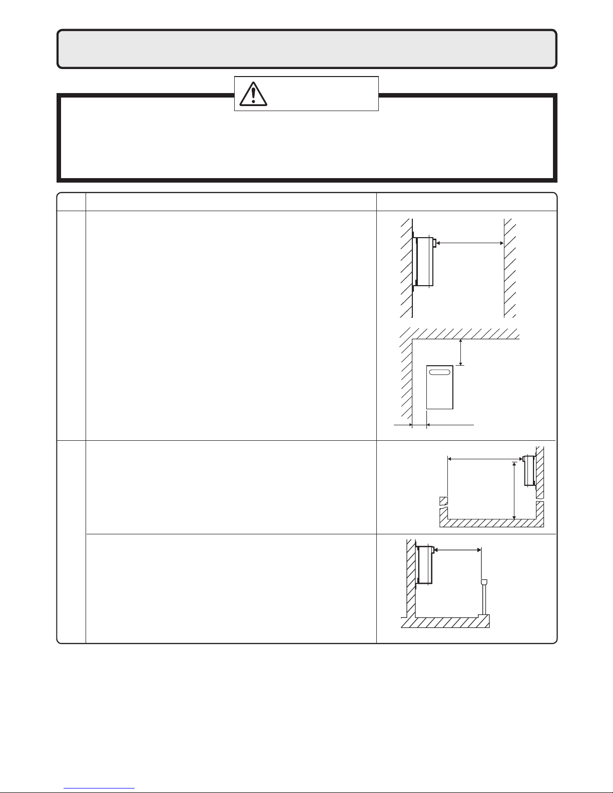
Installation Clearances
Before installing, check for the following:
Install in accordance with relevant building and mechanical codes, as well as any local, state or
national regulations, or in the absence of local and state codes, to the National Fuel Gas Code
ANSI Z223.1/NFPA 54 – latest edition. In Canada, see NSCNGPIC for detailed requirements.
WARNING
Item Check
• When installing the unit on a balcony, etc., secure an
evacuation route of 24" (600mm) or more in width.
• Provide clearance of 24" (600mm) or more in front of
the unit to facilitate inspection and repair. Do install the
unit such as the wall of the second oor where the unit
is out of reach.
• When installing the unit in a common side corridor, provide
a clearance of 47" (1,190mm) or more in front of the unit.
• Set the bottom edge of the exhaust port about
84" (2,130mm) from the corridor oor.
Handrail
common side
corridor
balcony, etc.
Handrail
about 84"
(2,130mm)
• Maintain the following clearance from both combustible
and non-combustible materials.
24" (600mm)
or more
36" (900mm)
or more
Surrounding the area of installation
24" (600mm)
or more
47" (1,190mm) or more
Required Clearances From Heater
Illustration
6" (150mm)
or more
7
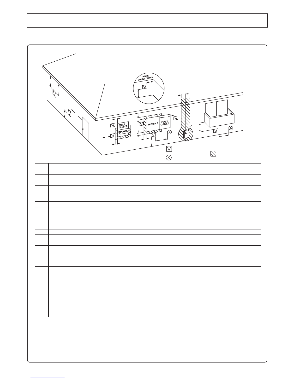
Clearance Requirements from Vent Terminations to Building Openings
* All clearance requirements are in accordance with ANSI Z21.10.3 and the National Fuel Gas Code,
ANSI Z223.1 and in Canada, in accordance with NSCNGPIC.
DescriptionRef
A=
Clearance above grade, veranda, porch,
deck, or balcony
B=
Clearance to window or door that may
be opened
C=
Clearance to permanently closed window
D=
Vertical clearance to ventilated soffit
located above the terminal within a
horizontal distance of 2 feet (61 cm)
from the center line of the terminal
*
E=
Clearance to unventilated soffit
*
F=
Clearance to outside corner
*
G=
Clearance to inside corner
*
H=
Clearance to each side of center line
extended above meter/regulator assembly
3 ft (91 cm) within a height
15 ft (4.5 m) above the
meter/regulator assembly
I=
Clearance to service regulator vent outlet
3 ft (91 cm)
J=
Clearance to nonmechanical air supply
inlet to building or the combustion air inlet
to any other appliance
K=
Clearance to a mechanical air supply inlet
6 ft (1.83 m)
L=
Clearance above paved sidewalk or paved
driveway located on public property
Clearance under veranda, porch, deck,
or balcony
7 ft (2.13 m)†
M=
1
In accordance with the current CSA B149.1 Natural Gas and Propane Installation Code
2
In accordance with the current ANSI Z223.1 / NFPA 54 National Fuel Gas Code
† A vent shall not terminate directly above a sidewalk or paved driveway that is located between two single
family dwellings and serves both dwellings.
‡ Permitted only if veranda, porch, deck, or balcony is fully open on a minimum of two sides beneath the floor.
* Clearance in accordance with local installation codes and the requirements of the gas supplier.
Clearance to opposite wall is 24 inches (60 cm).
12 in (30 cm)‡
*
12 in (30 cm)
36 in (91 cm)
*
*
*
*
*
*
*
*
3 ft (91 cm) above if within
10 ft (3 m) horizontally
*
12 in (30 cm)
4 ft (1.2 m) below or to side
of opening; 1 ft (30 cm)
above opening
36 in (91 cm)
4 ft (1.2 m) below or to side
of opening; 1 ft (30 cm)
above opening
US Non-Direct Vent
Installations
2
Canadian Non-Direct Vent
Installations
1
Vent Terminal
D
E
B
B
F
B
A
G
H
I
C
B
M
K
J
B
B
L
Air Supply Inlet
Area Where Terminal
is Not Permitted
A
8
Illustration
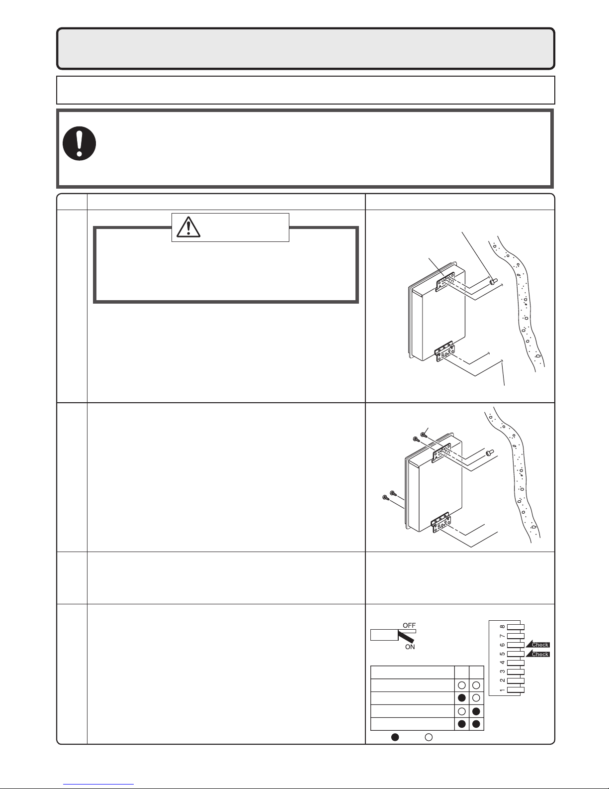
7.
Installation
Check
4. Drill holes for the remaining four screws.
5. Hang the unit again by the rst screw, and then
insert and tighten the remaining four screws.
6. Take waterproong measures so that water does
not enter the building from screws mounting the
device.
• Make sure the unit is installed securely so that it will
not fall or move due to vibrations or earthquakes.
Securing to the wall
1. Drill a single screw hole, making sure to hit a stud.
2. Insert and tighten the screw and hang the unit by
the upper wall mounting bracket.
3. Determine the positions for the remaining four screws
(two for the top bracket and two for the bottom), and
remove the unit.
• The weight of the device will be applied to the wall. If the strength of the wall is not suf-
cient, reinforcement must be done to prevent the transfer of vibration.
• Do not drop or apply unnecessary force to the device when installing. Internal parts may
be damaged and may become highly dangerous.
• Install the unit on a vertical wall and ensure that it is level.
Locating Screw Holes
Mounting
Structure
• When installing with bare hands, take caution to
not inict injury.
• Be careful not to hit electrical wiring, gas, or water
piping while drilling holes.
Item
CAUTION
Be sure to do
Mounting Bracket
(upper)
Anchoring Screw
(Arrangement at the eld)
Location of Screw Hole
Locating Screw Holes
Installations at Elevations
Above 2,000 ft.
• Adjust the dip switches as illustrated in the table to
the right if this water heater is installed at an altitude
of 2000 ft. (610m) or higher.
• Disconnect power to the water heater before chang-
ing the dip switches. Failure to perform this step will
result in a "73" code displayed on the remote controller and a cease in operation. If this occurs, discon-
nect, then reconnect power to the water heater to
reset the system.
Note : Please refer to page 19 for the location of the
dip switch bank.
* Do not change any other dipswitches.
* High elevation adjustment.
65
2,001 - 4,000 ft (611 - 1,220m)
0 - 2,000 ft (0 - 610m)
ON= OFF=
4,001 - 6,000 ft (1,221 - 1,830m)
6,001 - 8,000 ft (1,831 - 2,440m)
9
Gas Meter
Select a gas meter capable of supplying the entire
btuh demand of all gas appliances in the building.
Gas Connection
• Do not use piping with a diameter smaller than
the inlet diameter of the water heater.
• Gas flex lines are not recommended unless
they are rated for 180,000 btuh(NRC98-OD),
157,000 btuh(NRC83-OD).
• Install a gas shutoff valve on the supply line.
• Use only approved gas piping materials.
Follow the instructions from the gas supplier.
Gas Pressure
Size the gas line according to total btuh demand
of the building and length from the meter or
regulator so that the following supply pressures
are available even at maximum demand:
Natural Gas Supply Pressure
Min. 4" WC
Max. 10.5" WC
LP Gas Supply Pressure
Min. 8" WC
Max. 14" WC
8.
Gas Piping
The appliance and its individual shutoff valve must be disconnected from the gas supply piping system
during any pressure testing of that system at test pressures in excess of 1⁄2 psig (3.5 kPa).
The Appliance must be isolated from the gas supply piping system by closing its individual manual shut-
off valve during any pressure testing of the gas supply piping system at test pressures equal to or less
than
1
⁄2 psig (3.5 kPa).
The appliance and its gas connections must be leak tested before placing the appliance in operation.
The inlet gas pressure must be within the range specied. This is for the purposes of input adjustment.
In order to choose the proper size for the gas line, consult local codes or the National Fuel Gas Code
ANSI Z223.1.
Natural Gas
Meter
**See next page for the pipe capacity charts.
Noritz Condensing Tankless Gas Water Heater
(NRC98-OD 180,000 Btuh)
(NRC83-OD 157,000 Btuh)
Clothes Dryer
(35,000 Btuh)
Barbecue
(50,000 Btuh)
Gas Range Stove
(65,000 Btuh)
10' (3m)
10' (3m)
10' (3m)
10' (3m)
5' (1.5m)
5' (1.5m)
5' (1.5m)
5' (1.5m)5' (1.5m) 5' (1.5m)
Gas Fireplace
(25,000 Btuh)
Instructions
1. Size each outlet branch starting from the furthest
using the Btuh required and the length from the
meter.
2. Size each section of the main line using the
length to the furthest outlet and the Btuh
required by everything after that section.
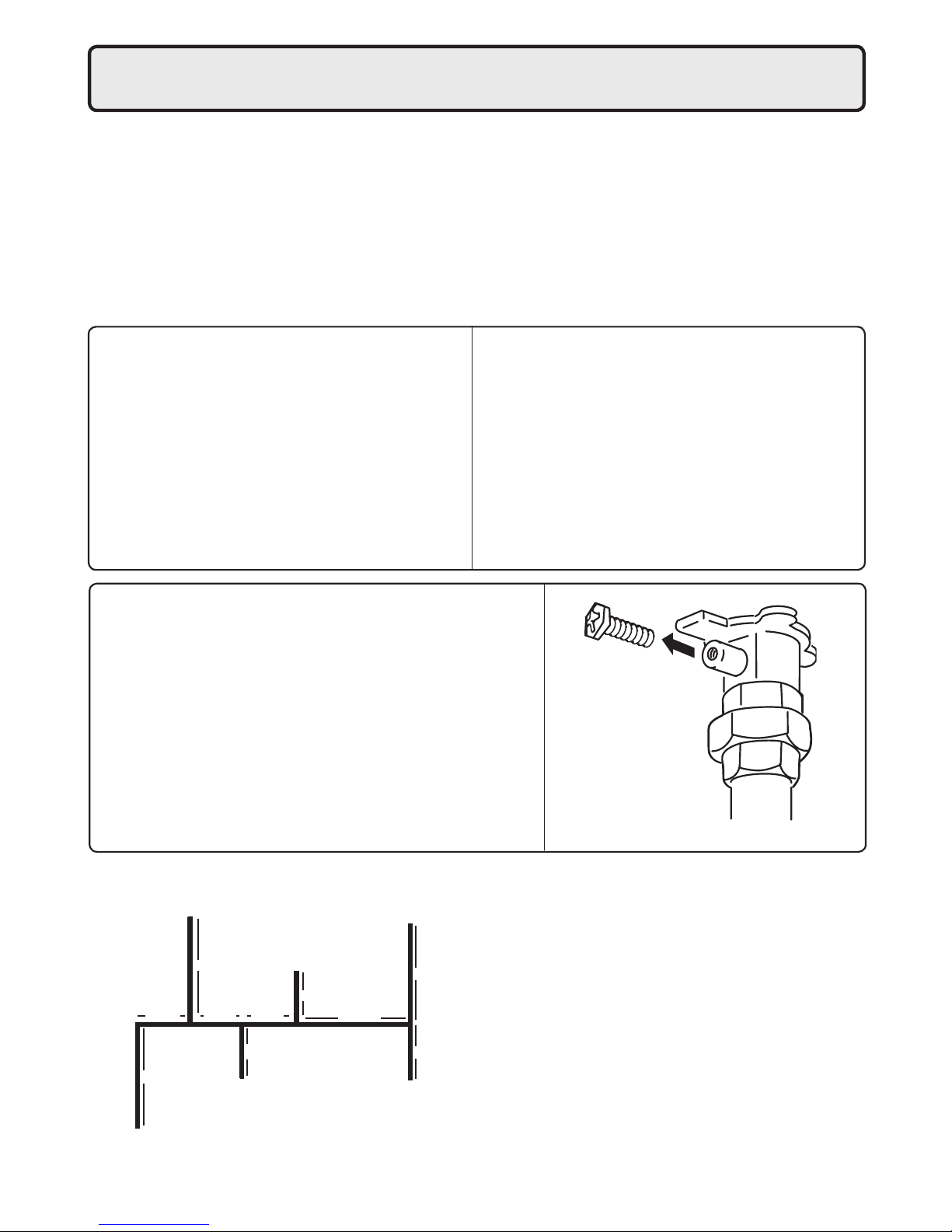
Sample Gas Line
Sample Calculation
Outlet A: 45' (13.5m) (Use 50' (15m)), 50,000 Btuh requires 1/2"
Outlet B: 40' (12m), 65,000 Btuh requires 1/2"
Section 1: 45' (13.5m) (Use 50' (15m)), 115,000 Btuh requires 3/4"
Outlet C: 30' (9m), 35,000 Btuh requires 1/2"
Section 2: 45' (13.5m) (Use 50' (15m)), 150,000 Btuh requires 3/4"
Outlet D: 25' (7.5m) (Use 30' (9m)), 25,000 Btuh requires 1/2"
Section 3: 45' (13.5m) (Use 50' (15m)), 175,000 Btuh requires 1"
Outlet E: 25' (7.5m) (Use 30' (9m)),
180,000 Btuh requires 3/4" (NRC98-OD),
157,000 Btuh requires 3/4" (NRC83-OD)
Section 4: 45' (13.5m) (Use 50' (15m)), 355,000 Btuh requires 1-1/4"
Section 3 Section 2
Section 1
Outlet A
Outlet B
Outlet C
Outlet D
Outlet E
Section 4
Measuring Gas Pressure
In order to check the gas supply pressure to the unit, a
tap is provided on the gas inlet. Remove the hex head
philips screw from the tap, and connect a manometer
using a silicon tube.
In order to check the gas manifold pressure, a pair of
taps are provided on the gas valve inside the unit.
The pressure can be checked either by removing the hex
head philips screw and connecting a manometer with a
silicon tube, or by removing the 1/8" NPT screw with an
allen wrench and connecting the appropriate pressure
gauge.
 Loading...