

Page 1
R24
Installation & Maintenance
Instructions
Warning - Feedback Pilot Regulators
Norgren manufacturers two types of feedback
pilot regulators (the R41 and the 11-104). Use
the R41, the 11-104-002, or the 11-104-003
feedback pilot regulator to control outlet
pressures greater than 100 psig (7 bar). Use
the Norgren 11-104-001 feedback pilot
regulator to control outlet pressures at or less
than 100 psig (7bar). The feedback line must
sense R24 outlet pressure and must be
connected before turning on air pressure. If
the feedback line is not connected, R24 outlet
pressure will rapidly increase to inlet pressure
when the feedback pilot adjusting knob is
turned clockwise.
4.
Install a pressure gauge in a gauge port on the R24, or
to the application point downstream of the R24. Do not
connect the gauge to the pilot pressure line, as this
pressure is not the same as the R24 outlet pressure. Locate
the gauge next to the pilot regulator. Plug unused gauge
ports.
5. Install a general purpose filter upstream of the regulator.
ADJUSTMENT
1. Before applying inlet pressure to regulators, turn pilot
regulator adjustment counterclockwise to remove all
force on regulating spring.
2. Apply inlet pressure, then turn pilot regulator adjustment
clockwise to increase and counterclockwise to decrease
pressure setting.
3. Always approach the desired pressure from a lower
pressure. When reducing from a higher to a lower
setting, first reduce to some pressure less than that
desired, then bring up to the desired pressure.
IM-414.240.01
(2/02)
Replaces NIP-245
Pilot Operated Regulator
© Norgren 2002
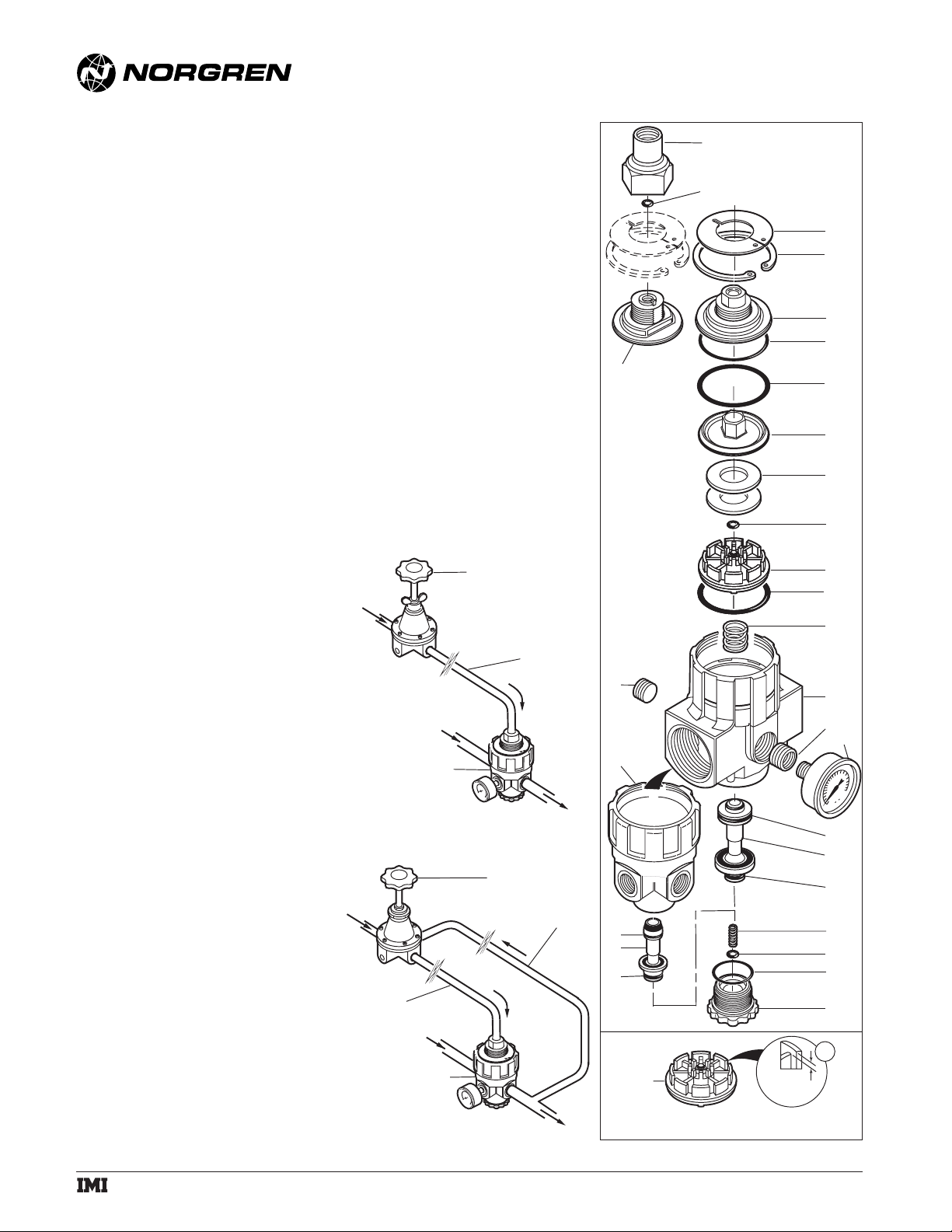
Figure 2. Feedback Pilot Installation
Figure 1. Conventional Pilot Installation
TECHNICAL DATA
Fluid: Compressed air
Inlet pressure range: 10 psig (0.7 bar) to 300 psig (20
bar). For best performance, inlet pressure should be
at least 10 psig (0.7 bar) greater than the desired
regulated pressure, but must not exceed the specified
maximum.
Operating temperature: 0° to +175°F (-20° to +80°C).
Air supply must be dry enough to avoid ice formation
at temperatures below +35°F (+2°C).
Typical flow at 150 psig (10.3 bar) inlet pressure,
90 psig (6.3 bar) set pressure, and 15 psig (1 bar)
droop from set:
1/2" ports:220 scfm (104 dm
3
/s)
1-1/4" ports: 700 scfm (330 dm3/s)
Maximum bleed rate at 50 psig (3.5 bar) outlet
pressure: 0.031 scfm (0.015 dm
3
/s). Maximum bleed
rate occurs under dead-end (no flow) conditions.
Port sizes:
Main Gauge Pilot
1/4" 1/4" 1/4"
3/8" 3/8" 1/4"
1/2", 3/4", 1", 1-1/4" 1/2" 1/4"
Thread type:
Main and gauge ports: PTF, ISO G, or ISO Rc
Pilot port: PTF with PTF main ports, ISO G with
ISO G and ISO Rc main ports
Materials:
Body, top cap: Zinc
Main valve, adjusting screw: Brass
Pilot valve, relief valve, bottom plug: Acetal
Elastomers: Nitrile
REPLACEMENT ITEMS
Service kit - 1/4", 3/8" 1/2" ported regulators
Items 2, 7, 9, 12, 13, 16, 17, 18, 19, 23 ..............5292-54
Service kit - 3/4", 1", 1-1/4" ported regulators
Items 2, 7, 9, 12, 13, 17, 20, 21, 22, 23 ..............5292-55
PANEL MOUNTING DIMENSIONS
Panel mounting hole diameter: 1.26" (32 mm)
Maximum panel thickness: 0.12" (3 mm)
INSTALLATION
1. Shut off air pressure. Install regulators in air line -
● upstream of lubricators and cycling valves.
● at any angle.
● install the R24 pilot operated regulator as close as
possible to the device being serviced.
● install the pilot regulator at any convenient, accessible
location.
2. Use pipe thread sealant on male threads only when
making the following pipe connections. Do not allow
sealant to enter interior of regulator.
● Connect inlet and outlet air lines to R24 main ports
with air flow in direction of arrow on body.
● Connect inlet and outlet air lines to the main ports of a
relieving type pilot regulator. The inlet port of the R40
and R41 is marked IN, and the outlet port is marked
OUT. The direction of air flow thru the 11-104 pilot is
indicated by an arrow on the bottom of the body.
● Connect the outlet of the pilot regulator to the pilot port
in the top cap of the R24. This is the pilot pressure line.
3.Special Instructions for a Feedback Pilot:
Connect one end of the feedback line to the feedback port
on the pilot regulator. The feedback port on the R41 is
marked FDBK. The 11-104 has two 1/8" PTF feedback
ports. Plug the unused feedback port. Connect the other
end of the feedback line to a gauge port on the R24 or, if
maximum precision pressure regulation is desired, to the
application point downstream of the R24. Keep the
feedback line as short as possible and unrestricted. Use
1/4" or 3/8 " OD copper tube for the feedback line. Plug
unused gauge ports.
CONVENTIONAL
SUPPLY
AIR
SUPPLY
AIR
PILOT OPERATED
REGULATOR
SUPPLY
AIR
PILOT
PRESSURE
LINE
SUPPLY
AIR
PILOT OPERATED
REGULATOR
PILOT REGULATOR
PILOT
PRESSURE
LINE
OUTLET AIR
FEEDBACK
PILOT REGULATOR
FEEDBACK
LINE
1
2
5
26
24
19
18
19
11
0.188"
(5mm)
3
4
6
7
9
8
10
12
11
13
14
25
27
28
21
20
22
23
16
17
15
A
a subsidiary of IMI plc
OUTLET
AIR
Page 2
R24
Installation & Maintenance
Instructions
WARNING
These products are intended for use in industrial
compressed air systems only. Do not use these products
where pressures and temperatures can exceed those listed
under Technical Data.
If outlet pressure in excess of the regulator pressure
setting could cause downstream equipment to rupture or
malfunction, install a pressure relief device downstream of
the regulator. The relief pressure and flow capacity of the
relief device must satisfy system requirements.
The accuracy of the indication of pressure gauges can
change, both during shipment (despite care in packaging)
and during the service life. If a pressure gauge is to be
used with these products and if inaccurate indications may
be hazardous to personnel or property, the gauge should be
calibrated before initial installation and at regular intervals
during use.
Before using these products with fluids other than air,
for non industrial applications, or for life-support systems
consult Norgren.
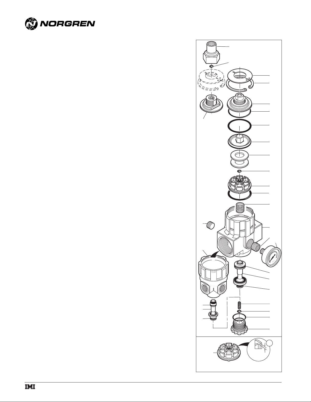
DISASSEMBLY
1. Regulator can be disassembled without removal from air
line.
2. Shut off inlet pressure to pilot regulator and to the R24.
Reduce pressure in inlet and outlet lines to zero.
3. Turn pilot regulator adjustment counterclockwise to
remove all force on regulating spring.
4. Disassemble in general accordance with the item numbers
on exploded view. On early models, unscrew adapter (1),
then remove o-ring (2). Current models do not use these
items.
WARNING
Prior to performing step 5, make certain air
pressure upstream and downstream of the R24
is at zero psi.
5. Use retaining ring pliers to remove the top plate (3) and
retaining ring (4). Pull cap (5 or 6) and o-ring (7) from
body.
6. Pull upper and lower piston assemblies (8 thru 13) from
body. Remove spring (14).
7. Unscrew bottom plug (15) to gain access to the parts (16
thru 23) located in the lower portion of the body.
CLEANING
1. Clean parts with warm water and soap.
2. Rinse and dry parts. Blow out internal passages in body
(24, 25) with clean, dry compressed air.
3. Inspect parts. Replace those found to be damaged.
ASSEMBLY
1. Lubricate o-rings and surfaces in contact with o-rings with
a light coat of good quality o-ring grease.
2. Place spring (14) in position in the body, then place the
upper and lower piston assembly (8 thru 13 *) in the
body. Place o-ring (7) in position on the cap (5 or 6) then
place cap in body.
3. Use retaining ring pliers to install retaining ring (4) and
top plate (3).
WARNING
Make sure retaining ring (4) is fully seated in the
groove in body.
4. On early models, install o-ring (2) and air pilot adapter (1).
5. Install lower section parts (16 thru 23) in body.
6. Torque Table
Item Torque Inch-Pounds (Nm)
1 (adapter
)
50 to 75 (5.6 to 8.5)
12 (Bottom plug) 20 to 30 (2.3 to 3.4)
* Two washers (10) are used on current R24 regulators.
Three washers were used on early R24 regulators
manufactured from September, 1993 to March, 1994. The
design of the piston (11) was changed in early 1994, and
one washer was eliminated. The washer support ribs on
the early pistons (Detail A of exploded view) are recessed
approximately 0.188" (5mm). The support ribs on current
pistons are recessed approximately 0.063" (2mm) . Use
only 2 washers (10) when replacing the early piston with a
current piston.
IM-414.240.02
(2/02)
Pilot Operated Regulator
© Norgren 2002
1
2
5
26
24
3
4
6
7
9
8
10
12
11
13
14
25
27
28
21
20
22
a subsidiary of IMI plc
0.188"
(5mm)
23
16
17
15
A
19
18
19
11
 Loading...