


Section 14
Lubricators
Compressed air tool lubricators are available in modular or inline models in port sizes from 1/8" to 2". Machine bearing lubricators are available in 8 to 32 inch ratings.
Contents
Lubricator Overview . . . . . . . . . . . . . . . . . . . . . . . . . . . . . . . . . . . . ALE-14-B L07 Miniature Micro-Fog® Lubricator 1/8" and 1/4" Ports . . . . . . . ALE-14-2 L72 Excelon Micro-Fog and Oil-Fog Lubricator
1/4" and 3/8" Ports . . . . . . . . . . . . . . . . . . . . . . . . . . . . . . . . . . . ALE-14-4 L73 Excelon Micro-Fog and Oil-Fog Lubricators
1/4", 3/8", and 1/2" Ports . . . . . . . . . . . . . . . . . . . . . . . . . . . . . . ALE-14-6 L74 Excelon Micro-Fog and Oil-Fog Lubricators
3/8", 1/2", and 3/4" Ports . . . . . . . . . . . . . . . . . . . . . . . . . . . . . . . ALE-14-8 L64 Olympian Plus Micro-Fog and Oil-Fog Lubricators
1/4", 3/8", 1/2", and 3/4" Ports. . . . . . . . . . . . . . . . . . . . . . . . . . ALE-14-10 L68 Olympian Micro-Fog and Oil-Fog Lubricator
3/4", 1, 1-1/4", and 1-1/2" Ports . . . . . . . . . . . . . . . . . . . . . . . . . ALE-14-12 L17 Micro-Fog and Oil-Fog Lubricators
3/4", 1", 1-1/4" and 1-1/2" Ports . . . . . . . . . . . . . . . . . . . . . . . . ALE-14-14 10-028 Oil-Fog Lubricator 1-1/2" Port . . . . . . . . . . . . . . . . . . . . . . ALE-14-16 10-076 Oil-Fog Lubricator 2" Port . . . . . . . . . . . . . . . . . . . . . . . . . ALE-14-18 10-015 Micro-Fog Machine Bearing Lubricator,
8 to 32 Bearing Inch Ratings, 1/4" Port . . . . . . . . . . . . . . . . . . ALE-14-20
L07 |
L72M/C |
L73M/C |
L74M/C |
L64M/C |
L68 |
L17 |
10-028 |
10-076 |
10-015 |
|
|
|
|
|
|
|
|
Littleton, CO USA |
Phone 303-794-2611 |
Fax 303-795-9487 |
ALE-14-A |
|

Lubricator Overview
1.1GENERAL OVERVIEW
Norgren manufactures two main types of lubricators: Oil-Fog and Micro-Fog. These units are mounted directly into the pipe and add small amounts of oil to the air flowing through them.
Oil Fog-Lubricators:
All the oil droplets seen in the sight dome are added directly into the air flow. This results in relatively large oil droplets passing downstream, suitable for heavy lubrication applications eg single cylinders and tools. Most competitive in line lubricators are of the Oil-Fog type.
Micro-Fog Lubricators:
The oil droplets seen in the sight dome are atomized and collected in the area above the oil in the bowl. The smaller lighter particles are drawn into the air flow and pass downstream.
As a result typically only 10% of the oil seen as drops in the sight dome is passed downstream. The remainder falls back into the oil reservoir. Consequently, drip rate settings are somewhat higher than their Oil-Fog equivalent. This makes setting much easier, particularly in low flow applications.
The fine Micro-Fog oil particles can travel long distances through complex pipe work making Micro-Fog lubricators suitable for multiple valve and cylinder circuits.
1.2WHAT ARE THE DIFFERENCES BETWEEN MICRO-FOG AND OIL-FOG?
1.2.1Oil-Fog:
•Large oil particles not as fine as micro-fog.
•All oil drips seen in sight domes are delivered downstream.
•For applications over short distances.
•Should be mounted at same level or higher than device being lubricated.
•Standard bowls can be filled under pressure. (Not on rapid cycle units).
•Suitable for heavy lubrication applications eg single large cylinders and tools.
•Has a flow sensor which provides constant oil output density for varying flows.
OIL-FOG LUBRICATOR
Sight dome
|
Body |
|
Flow |
|
sensor |
|
Check |
|
valve |
|
Bowl |
Metal bowl |
Syphon |
sight glass |
tube |
|
Oil |
|
Drain |
|
(optional) |
MICRO-FOG LUBRICATOR
|
Sight |
|
dome |
|
Body |
|
Flow |
|
sensor |
|
Generator |
|
assembly |
|
Bowl |
Metal bowl |
|
sight glass |
Syphon |
|
tube |
|
Oil |
|
Drain |
|
(optional) |
1.2.2Micro-Fog:
•Small oil particles; less than 2 micron.
•Only 10% of ‘drip rate’ is delivered downstream as active lubricant (remainder is returned to main oil reservoir).
•High drip rates make drip setting easier in low flow applications.
•Can be mounted above or below the point of application.
•Cannot be filled without shutting off upstream air (unless a quick fill cap or remote fill device is used).
•For use with lengthy air lines, multiple valve and cylinder circuits.
•Has a flow sensor to provide an almost constant oil output density for varying flows.
1.2.3 Can Oil-Fog and Micro-Fog Units be Converted?
Generally not, simply changing a green (Oil-Fog) sight dome for a red (Micro-Fog) sight dome does not change the function.
Some lubricators are designed around a cartridge insert. In this case it may be possible to swap the cartridge and sight domes to change the function.
ALE-14-B |
Littleton, CO USA |
Phone 303-794-2611 |
Fax 303-795-9487 |

Lubricator Overview
|
bar |
|
|
psig |
|
|
|
|
|
|
|
|
Flow Characteristics |
|
|
|
|
|
|
|
|
|
||||||||||||||||
|
|
|
|
|
|
|
|
|
|
|
|
|
|
|
|
|
|
|
|
|
|
|
|
|
|
|
|
|
|
|
|
|
|
|
|
|
||
|
.5 |
|
|
|
|
|
|
|
|
|
|
|
|
|
|
|
|
|
|
|
|
|
|
|
|
|
|
|
|
|
|
|
|
|
|
|
|
|
|
|
7 |
|
|
|
|
|
|
|
|
|
35 |
|
|
60 |
|
|
|
90 |
|
|
120 |
|
160 |
|
180 psig |
|
|
||||||||||
|
|
|
|
|
|
|
|
|
|
|
|
|
|
|
|
|
|
|
|
|||||||||||||||||||
|
|
|
|
|
|
|
|
|
|
|
|
|
|
|
|
|
|
|
|
|
|
|
|
|
|
|
|
|
|
|
|
|
|
|
|
|
|
|
Drop |
.4 |
|
|
6 |
|
|
|
|
|
|
|
|
|
|
|
|
|
|
|
|
|
|
|
|
|
|
|
|
|
|
|
|
|
|
|
|
|
|
|
|
|
|
|
|
|
|
|
|
|
|
|
|
|
|
|
|
|
|
|
|
|
|
|
|
|
|
|
|
|
|
|
|
|
|
|||
|
|
|
|
|
|
|
|
|
|
|
|
|
|
|
|
|
|
|
|
|
|
|
|
|
|
|
|
|
|
|
|
|
|
|
|
|||
|
|
5 |
|
|
|
|
|
|
|
|
|
|
|
|
|
|
|
|
|
|
|
|
|
|
|
|
|
|
|
|
|
|
|
|
|
|
||
.3 |
|
|
|
|
|
|
|
|
|
|
|
|
|
|
|
|
|
|
|
|
|
|
|
|
|
|
|
|
|
|
|
|
|
|
|
|
||
Pressure |
|
|
|
|
|
|
|
|
|
|
|
|
|
|
|
|
|
|
|
|
|
|
|
|
|
|
|
|
|
|
|
|
|
|
|
|
||
|
|
4 |
|
|
|
|
|
|
|
|
|
|
|
|
|
|
|
|
|
|
|
|
|
|
|
|
|
|
|
|
|
|
|
|
|
|
||
|
|
|
|
|
|
|
|
|
|
|
|
|
|
|
|
|
|
|
|
|
|
|
|
|
|
|
|
|
|
|
|
|
|
|
|
|||
|
|
|
|
|
|
|
|
|
|
|
|
|
|
|
|
|
|
|
|
|
|
|
|
|
|
|
|
|
|
|
|
|
|
|
|
|
|
|
|
.2 |
|
|
3 |
|
|
|
|
|
|
|
|
|
|
|
|
|
|
|
|
|
|
|
|
|
|
|
|
|
|
|
|
|
|
|
|
|
|
|
|
|
|
|
|
|
|
|
|
|
|
|
|
|
|
|
|
|
|
|
|
|
|
|
|
|
|
|
|
|
|
|
|
|
|
|
||
|
|
|
|
|
|
|
|
|
|
|
|
|
|
|
|
|
|
|
|
|
|
|
|
|
|
|
|
|
|
|
|
|
|
|
|
|
||
|
|
|
2 |
|
|
|
|
|
|
|
|
|
|
|
|
|
|
|
|
|
|
|
|
|
|
|
|
|
|
|
|
|
|
|
|
|
|
|
|
.1 |
|
|
|
|
|
|
|
|
|
|
|
|
|
|
|
|
|
|
|
|
|
|
|
|
|
|
|
|
|
|
|
|
|
|
|
|
|
|
|
|
|
|
|
|
|
|
|
|
|
|
|
|
|
|
|
|
|
|
|
|
|
|
|
|
|
|
|
|
|
|
|
|
|
|||
|
|
|
1 |
|
|
|
|
|
|
|
|
|
|
|
|
|
|
|
|
|
|
|
|
|
|
|
|
|
|
|
|
|
|
|
|
|
|
|
|
|
|
|
|
|
|
|
|
|
|
|
|
|
|
|
|
|
|
|
|
|
|
|
|
|
|
|
|
|
|
|
|
|
|
|
|
||
|
|
|
|
|
|
|
|
|
|
|
|
|
|
|
|
|
|
|
|
|
|
|
|
|
|
|
|
|
|
|
|
|
|
|
|
|
|
|
|
|
|
|
|
|
|
|
|
|
|
|
|
|
|
|
|
|
|
|
|
|
|
|
|
|
|
|
|
|
|
|
|
|
|
|
|
|
|
|
0 |
|
|
0 |
|
|
|
|
|
|
|
|
|
|
|
|
|
|
|
|
|
|
|
|
|
|
|
|
|
|
|
|
|
|
|
|
|
|
|
|
|
0 |
20 |
40 |
60 |
80 |
|
100 |
120 |
140 |
160 |
180 |
200 |
|
scfm |
||||||||||||||||||||||
|
|
|
|
|
|
|
|
|
|
|
|
|
|
|
|
|
|
|
|
|
|
|
|
|
|
|
|
|
|
|
|
|
|
|
|
|
|
|
|
|
|
|
|
|
|
|
|
|
|
|
|
|
|
|
|
|
|
|
|
|
|
|
|
|
|
|
|
|
|
|
|
|
|
|
|
||
|
|
|
0 |
10 |
20 |
30 |
40 |
50 |
60 |
70 80 |
|
90 100 |
dm 3/s |
|||||||||||||||||||||||||
Air Flow
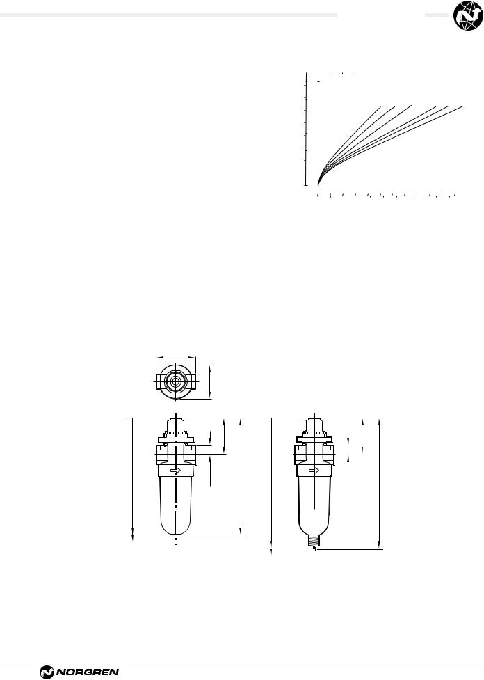
1.3LUBRICATOR SIZING
Lubricators are sized by downstream flow requirements. An analysis of air flow use must be made. After determining how much air flow is needed, a lubricator can be chosen. Manufacturers’ curves will be like the one shown. For example, 50 scfm of 90 psig lubricated air is required. Enter the curve on the horizontal axis at the required flow. Read up to intersect the 90 psig line. Read the pressure drop on left, vertical axis as approximately 2.3 psid. Pressure drop should be less than 5 psid. If pressure drop is more than 5 psid, choose a larger lubricator.
Always be sure that the lubricants in your system are compatible with the materials in the lubricator you choose. This is especially important for plastic lubricator reservoirs. If in doubt, check with the factory or use a metal reservoir.
1.4SETTING LUBRICATOR DRIP RATES
1.4.1What is the Correct Drip Rate Setting?
The drip rate will depend on the application, the amount of lubrication required, the flow through the lubricator and the lubricator type. In Micro-Fog lubricators only 10% of the droplets in the sight dome are carried downstream. The drip rate in Micro-Fog lubricators therefore tends to be much higher.
The following table can be used to estimate drip rate for required flow. This is very much a rule of thumb. In practice it is necessary to fine tune the oil drip rate in each application.
Typical Drip Rate |
Typical Drip Rate |
Approx |
|
per Minute |
per Minute |
Flow |
|
Micro-Fog |
Oil-Fog |
scfm |
|
|
|
(dm3/s) |
|
20 |
2 |
10 |
(5) |
40 |
4 |
20 |
(10) |
60 |
6 |
30 |
(15) |
80 |
8 |
40 |
(20) |
100 |
10 |
50 |
(25) |
120 |
12 |
60 |
(30) |
1.3.2Can the Drip Rate be Shut Off?
In lubricators with needle valve type sight dome, yes.
Some Norgren sight domes use a felt pad which is soaked in oil at the point where the drops are formed. With this type of sight dome the oil droplets cease once the felt pad dries out.
With the new style dome (L72/73/74 and L07) complete shut off is not possible. Minimum adjustment for the drip rate is around 1 drop per minute.
1.5FILLING METHODS
1.5.1Oil-Fog and Micro-Fog Lubricators:
The standard Oil-Fog lubricators can be filled under pressure ie without switching off the upstream air. When a fill plug is removed a check valve in the lubricator body isolates the inlet pressure from the bowl and the reservoir will depressurize. The lubricator can then be filled with oil. When the fill plug is replaced, the reservoir will re-pressurize.
The standard Micro-Fog unit can only be filled without isolating the upstream pressure if a remote fill or quick fill nipple accessory is fitted. To remove the fill plug of a Micro-Fog lubricator whilse under pressure can be dangerous. If in doubt shut off the upstream air!
1.5.2Remote Fill Devices:
The remote oil fill system provides a means of filling from a remote fill point, a single lubricator or a bank of lubricators manifolded together. The remote fill point may be connected to a portable reservoir or to a centralized, permanent reservoir. A portable reservoir permits the use of different lubricants in different groups of lubricators to suit the requirements of the machinery being lubricated. The lubrication oil must be fed in at a higher pressure than exists in the bowl.
The devices are NOT intended for connection to an oil feed line which is under constant pressure from a pump or pressurized reservoir. The device cannot reset until the pressure is removed. Such lines are a potential safety hazard if they should leak or become broken.
1.5.3Quick Fill Nipples:
The quick fill system is an alternative which allows ease of filling a single Micro-Fog or Oil-Fog lubricator without switching off the mains air (on some units the quick fill nipple replaces the filler plug).
To fill the lubricator, a quick fill connector piped to a portable oil reservoir is snapped in place over the quick fill nipple. The main oil reservoir can now be pumped (or pressurized) to a pressure greater than the lubricator bowl and the lubricator filled.
Littleton, CO USA |
Phone 303-794-2611 |
Fax 303-795-9487 |
ALE-14-C |

Lubricator Overview
1.6OPTIONS AND ACCESSORIES
1.6.1Where can Liquid Level Switches be Fitted?
Liquid level detection methods can be attached to the 1 quart bowl and 2 & 5 gallon tanks.
1.6.2Where can Remote Fill and Liquid Level Switches be Fitted?
1.7LARGE TANKS/RESERVOIRS
1.7.1Which Units have Large Tanks/Reservoirs?
All units in basic 1/2” and above have optional larger bowls/tanks.
Olympian Plus and Excelon 74 are limited to 1 quart as standard. For 2 and 5 gallon capacity use 15/17 Series, or the 10-028/-076 (2”) lubricators.
The smaller bowls, L73 and up, are all capable of either remote fill or liquid level detection (but not both at the same time!). The 2 quart and 2 & 5 gallon tanks only can have the liquid level switches fitted.
1.6.3How do Liquid Level Switches Work?
Liquid level switches are bipolar reed switches which change state when the float rises and falls.
Liquid level switches are normally connected to give an electrical signal when the float falls (ie when the liquid level is too low). In critical applications the logic could be reversed. Maximum and minimum settings are possible too.
1.8APPLICATION SPECIFIC UNITS
1.8.1Do we Make Bearing Lubricators?
These are aerosol type lubricators. These lubricators use air to get the oil to the point of lubrication, however the tool or application is not powered by the air. Although produced by Norgren, systems for their application are designed and sold by Engineering and General Lubrication Systems.
1.8.2What is a Fixed Venturi (Bi-Directional) Lubricator?
Standard Norgren lubricators use a flow sensor to achieve constant oil density with varying flows. In some applications high flow is more important than constant density and a fixed venturi can be used instead of a flow sensor. It may also be useful in systems with rapid cycling. Consult Air Line for more details.
1.9OILS
1.9.1What Oils are Recommended?
Recommended oils fall into 2 categories:-
1Oils recommended for use with all Norgren units (valves, cylinders, fittings and FRL’s).
2Oils which can be used with Norgren
lubricators but not necessarily with other Norgren equipment.
Refer to ALE-29-2 for recommended lubricants.
1.9.2Can Non-Recommended Oils be Used?
Some oils can be tested for suitability, but Norgren cannot be responsible for use of non-recommended lubricants.
ALE-14-D |
Littleton, CO USA |
Phone 303-794-2611 |
Fax 303-795-9487 |

|
|
|
Lubricators Overview |
|
|
|
|
|
|
|
|
||
|
1.10 SIMPLE LUBRICATOR TROUBLESHOOTING |
|
|
|||
|
|
|
|
|
||
|
Problem |
Possible Cause |
Remedy |
|
||
|
|
|
|
|
||
|
No Drip Rate |
Oil adjustment knob fully clockwise. |
Readjust knob. |
|
||
|
|
Low oil level. |
Check oil level. |
|
||
|
|
Airflow through lubricator too low. |
Use smaller size lubricator. |
|
||
|
|
|
Remove bowl and sight feed adjustment dome and |
|
||
|
|
|
clear syphon tube. |
|
||
|
|
Blocked oil filter screen. |
Remove sight feed adjustment dome and clean or |
|
||
|
|
|
replace screen located in dome assembly. |
|
||
|
|
Air leaks. |
Check bowl, filler plug and sight dome seals. |
|
||
|
|
|
Tighten if necessary. |
|
||
|
|
|
|
|
||
|
Oil Foaming |
Over aeration. |
Check bowl seals for slight leaks. |
|
||
|
|
|
|
|
||
|
Oil Emulsified |
Water in lubricator. |
Fit filter immediately upstream. |
|
||
|
|
|
|
|
||
|
Drip Rate changes after setting |
Fade. |
Readjust drip rate. |
|
||
|
|
|
|
|
|
|
Littleton, CO USA |
Phone 303-794-2611 |
Fax 303-795-9487 |
ALE-14-E |
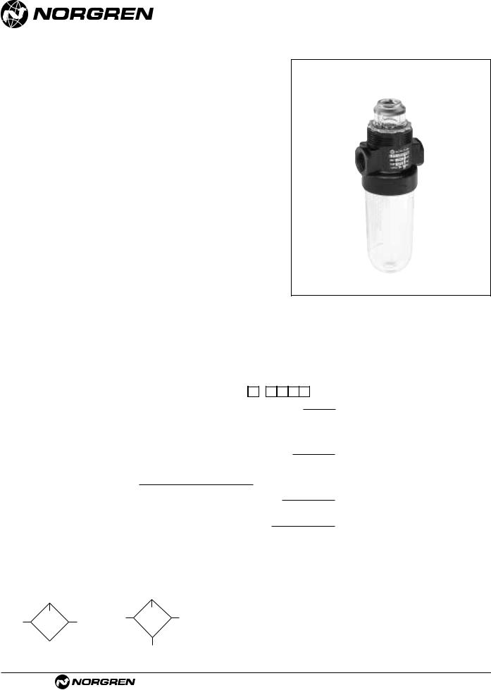
L07
Miniature Series 07 Micro-Fog
Lubricator 1/8" and 1/4" Port Sizes
●Compact design
●Provides air line lubrication to one or more air driven tools or other devices
●Nearly constant oil density output with varying air flow
●All around (360°) visibility of the sight-feed dome simplifies installation and adjustment
●Screw-on bowl reduces maintenance time
●Can be disassembled without the use of tools or removal from the air line
Ordering Information. Models listed include PTF threads and transparent bowl with manual drain.
Port Size |
Model Numbers |
Flow scfm (dm3/s)* |
Weight lbs (kg) |
1/8" |
L07-100-MPAA |
10 (5.0 dm3/s) |
0.28 (0.13) |
1/4" |
L07-200-MPAA |
14 (6.7 dm3/s) |
0.28 (0.13) |
* Approximate flow at 90 psig (6.3 bar) inlet pressure and 7 psig (0.5 bar) pressure drop.
Alternative Models |
|
|
L |
0 |
7 |
- |
|
|
|
- |
M |
P |
|
|
||||||||
|
|
|
|
|
|
|
|
|
|
|
|
|
|
|
|
|
|
|
|
|
|
|
Port Size |
Substitute |
|
|
|
|
|
|
|
|
|
|
|
|
|
|
|
|
|
|
|
|
|
|
|
|
|
|
|
|
|
|
|
|
|
|
|
|
|
|
|
|
|
|
||
1/8" |
1 |
|
|
|
|
|
|
|
|
|
|
|
|
|
|
|
|
|
|
|
|
|
1/4" |
2 |
|
|
|
|
|
|
|
|
|
|
|
|
|
|
|
|
|
|
|
|
|
|
|
|
|
|
|
|
|
|
|
|
|
|
|
|
|
|
|
|
|
|
|
|
Option |
Substitute |
|
|
|
|
|
|
|
|
|
|
|
|
|
|
|
|
|
|
|
|
|
|
|
|
|
|
|
|
|
|
|
|
|
|
|
|
|
|
|
|
||||
Not applicable |
0 |
|
|
|
|
|
|
|
|
|
|
|
|
|
|
|
|
|
|
|
|
|
|
|
|
|
|
|
|
|
|
|
|
|
|
|
|
|
|
|
|
|
|
|
|
Option |
Substitute |
|
|
|
|
|
|
|
|
|
|
|
|
|
|
|
|
|
|
|
||
|
|
|
|
|
|
|
|
|||||||||||||||
Not applicable |
0 |
|
|
|
|
|
|
|
|
|
|
|
|
|
|
|
|
|
|
|
|
|
|
|
|
|
|
|
|
|
|
|
|
|
|
|
|
|
|
|
|
|
|
|
|
Threads |
Substitute |
|
PTF |
A |
|
ISO Rc taper |
B |
|
ISO G parallel |
G |
|
|
|
|
Bowl and Drain |
Substitute |
|
Transparent without drain |
Q |
|
Metal with drain |
M |
|
Transparent with drain |
A |
|
|
|
|
Flow |
Substitute |
|
Unidirection |
P |
|
|
|
|
Lubricator Type |
|
Substitute |
Micro-Fog |
|
M |
ISO Symbols
No drain |
Manual drain |
See Section ALE-25 for Accessories
ALE-14-2 |
Littleton, CO USA |
Phone 303-794-2611 |
Fax 303-795-9487 |
Technical Data
Fluid: Compressed air
Maximum pressure
Transparent bowl: 150 psig (10 bar)
Metal bowl: 250 psig (17 bar)
Operating temperature*
Transparent bowl: 0° to 125°F (-20° to 50°C)
Metal bowl: 0° to 175°F (-20° to 80°C)
*Air supply must be dry enough to avoid ice formation at temperatures below 35°F (2°C)
Start point (i.e. minimum flow required for lubricator operation): 0.5 scfm (0.24 dm3/s) at 90 psig (6.3 bar) inlet pressure
Typical flow at 90 psig (6.3 bar) inlet pressure at 7 psig (0.5 bar) pressure drop:
1/8" ports: 10 scfm (5 dm3/s) 1/4" ports: 14 scfm (6.7 dm3/s)
Nominal bowl size: 1 fluid ounce (31 ml)
Drain connection: Will fit 1/8-27 and 1/8-28 pipe thread
Recommended lubricants: See Section ALE-29. Materials
Body: Zinc Bowl
Transparent: Polycarbonate Metal: Zinc
Sight-feed dome: Transparent nylon
Elastomers: Neoprene & nitrile
All Dimensions in Inches (mm)
Panel mounting hole diameter: 1.9" (30 mm)
Maximum panel thickness: 0.25” (6 mm)
|
1.63 (41) |
|
|
|
1.45 (37) |
|
|
|
|
1.65 (42) |
|
7.21 (183)† |
0.38 (10) |
4.72 (120) |
7.60 (193)† |
Without Drain
† Minimum clearance to remove bowl.
L07 Lubricators
Typical Performance Characteristics
|
|
|
|
|
|
|
|
|
FLOW CHARACTERISTICS |
|
|
|
|
|
|
|
|
|
||||||||
|
bar d |
psid |
|
|
|
|
|
|
|
|
|
|
|
|
|
|
|
|
|
|
|
|
|
|
|
|
|
|
PORT SIZE: 1/4" |
|
|
|
|
|
|
|
|
|
|
|
|
|
|
|
|
|
|
||||||
|
0.8 |
|
|
|
|
|
|
|
|
|
|
|
|
|
|
|
|
|
|
|
|
|
|
|
|
|
|
|
|
|
|
|
|
|
|
|
|
|
INLET PRESSURE: psig (bar g) |
|
|
|
|
|
|||||||||
|
|
|
|
|
|
|
|
|
|
|
|
|
|
|
|
|
|
|||||||||
|
|
10 |
|
|
|
|
|
|
|
|
23 |
36 |
58 |
|
91 |
116 |
150 |
|
|
|
||||||
DROOP |
|
|
|
|
|
|
|
|
|
|
(1.6) |
(2.5) |
(4.0) |
(6.3) |
(8) |
(10) |
|
|
|
|||||||
0.6 |
|
|
|
|
|
|
|
|
|
|
|
|
|
|
|
|
|
|
|
|
|
|
|
|
|
|
|
|
|
|
|
|
|
|
|
|
|
|
|
|
|
|
|
|
|
|
|
|
|
|
|
|
|
PRESSURE |
|
8 |
|
|
|
|
|
|
|
|
|
|
|
|
|
|
|
|
|
|
|
|
|
|
|
|
|
|
|
|
|
|
|
|
|
|
|
|
|
|
|
|
|
|
|
|
|
|
|
|
|||
0.4 |
6 |
|
|
|
|
|
|
|
|
|
|
|
|
|
|
|
|
|
|
|
|
|
|
|
|
|
|
|
|
|
|
|
|
|
|
|
|
|
|
|
|
|
|
|
|
|
|
|
|
|
|
||
|
|
|
|
|
|
|
|
|
|
|
|
|
|
|
|
|
|
|
|
|
|
|
|
|
|
|
|
0.2 |
4 |
|
|
|
|
|
|
|
|
|
|
|
|
|
|
|
|
|
|
|
|
|
|
|
|
|
|
|
|
|
|
|
|
|
|
|
|
|
|
|
|
|
|
|
|
|
|
|
|
|||
|
|
|
|
|
|
|
|
|
|
|
|
|
|
|
|
|
|
|
|
|
|
|
|
|
|
|
|
|
2 |
|
|
|
|
|
|
|
|
|
|
|
|
|
|
|
|
|
|
|
|
|
|
|
|
|
|
|
|
|
|
|
|
|
|
|
|
|
|
|
|
|
|
|
|
|
|
|
|
|
||
|
0 |
0 |
|
|
|
|
|
|
|
|
|
|
|
|
|
|
|
|
|
|
|
|
|
|
|
|
|
|
|
|
|
|
|
|
|
|
|
|
|
|
|
|
|
|
|
|
|
|
|
|
|||
|
|
0 |
4 |
|
8 |
|
|
|
12 |
16 |
|
20 |
24 |
|
scfm |
|||||||||||
|
|
|
|
|
|
|
|
|
|
|
|
|
|
|
|
|
|
|
||||||||
|
|
0 |
2 |
|
4 |
|
|
|
6 |
8 |
|
10 |
|
|
|
dm3/s |
||||||||||
|
|
|
|
|
|
|
|
|
|
|
|
|
AIR FLOW |
|
|
|
|
|
|
|
|
|
||||
Service Kits |
|
|
|
|
|
|
|
|
|
|
|
|
|
|
|
|
|
|
||||||||
|
|
|
|
|
|
|
|
|
|
|
|
|
|
|
|
|
||||||||||
|
Item |
|
|
|
|
|
|
|
Type |
|
|
|
|
|
|
Part number |
||||||||||
|
Service kit |
|
Seal and o-ring |
|
3795-03 |
|
|
|
||||||||||||||||||
|
Replacement drain |
|
Manual |
|
|
|
|
|
773-03 |
|
|
|
|
|||||||||||||
Service kit includes o-ring, seal, and bowl o-ring.
|
|
1.65 (42) |
|
|
|
|
|
||
|
|
|
||
|
|
|||
|
|
|
|
|
0.38 (10) |
|
(130) |
||
|
||||
|
|
5.12 |
||
Manua Drain
Littleton, CO USA |
Phone 303-794-2611 |
Fax 303-795-9487 |
ALE-14-3 |
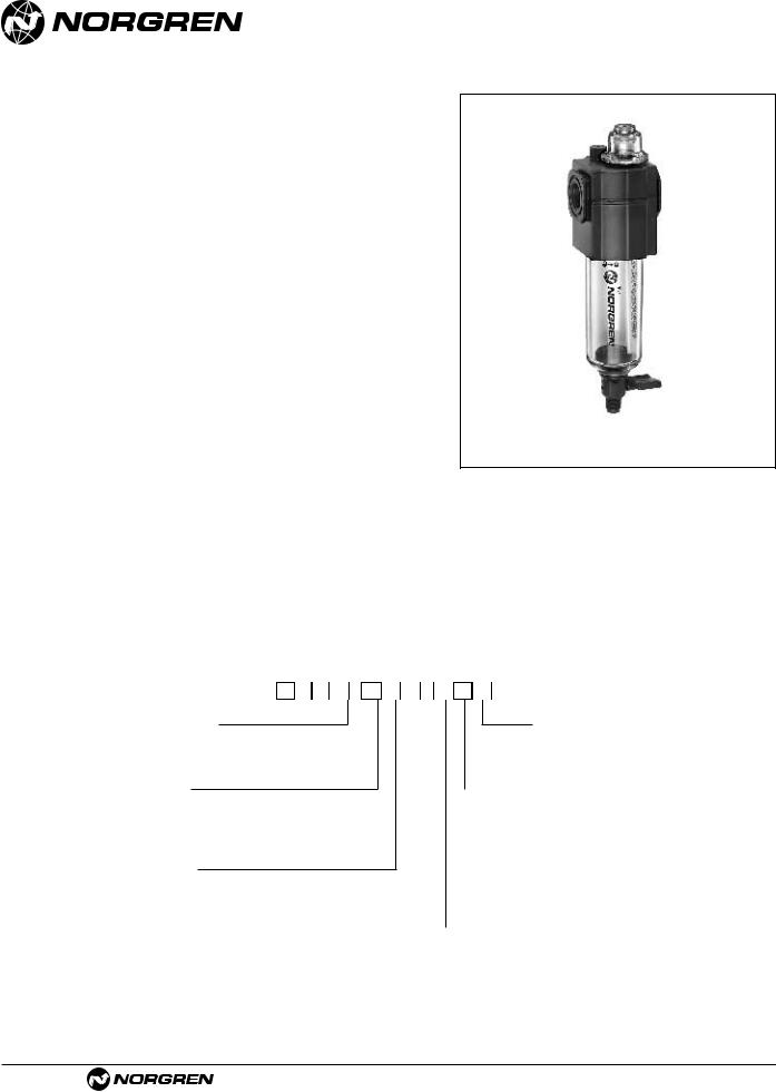
L72M, L72C
Excelon 72 Micro-Fog and Oil-Fog
Lubricator 1/4", 3/8" Port Sizes
●Excelon design allows in-line or modular installation
●Quick release bayonet bowl
●Flow sensor provides a consistent oil/air ratio over a wide range of flows
●Highly visible, prismatic liquid level indicator lens on metal bowls
●All round (360°) visibility of sight-feed dome for ease of drip rate setting
●Modular installations with Excelon 72, 73, and 74 series can be made to suit particular applications
Use Micro-Fog models in applications with one or more points of lubrication.
Use Oil-Fog models to lubricate a single tool, cylinder or other air driven device.
Ordering Information. Models listed include PTF threads, manual drain, and long transparent bowl without guard.
Type |
Main Port Size |
Model Number |
Flow* scfm (dm3/s) |
Weight lb (kg)† |
Micro-Fog |
1/4" |
L72M-2AP-QLN |
51 (24) |
1.1 (0.49) |
|
3/8" |
L72M-3AP-QLN |
51 (24) |
1.1 (0.49) |
Oil-Fog |
1/4" |
L72C-2AP-QLN |
51 (24) |
1.1 (0.49) |
|
3/8" |
L72C-3AP-QLN |
51 (24) |
1.1 (0.49) |
*Typical flow with 90 psig (6.3 bar) inlet pressure and a pressure drop of 7 psig (0.5 bar).
Alternative Models |
L 7 2 |
- P - |
|
Type |
|
Substitute |
|
|
|
|
Options |
Substitute |
||
Oil-Fog |
|
|
C |
|
|
|
|
None |
N |
|
Micro-Fog |
|
|
M |
|
|
|
|
|
|
|
|
|
|
|
|
|
Pyrex dome |
P† |
|||
|
|
|
|
|
|
|
|
|
|
|
Port Size |
|
Substitute |
|
|
|
|
Bowl |
Substitute |
||
|
|
|
|
|
|
|
|
|
Short metal with plastic liquid level indicator |
D |
1/4" |
|
2 |
|
|
|
|
|
|||
|
|
|
|
|
|
Short metal with Pyrex liquid level indicator |
R |
|||
3/8" |
|
3 |
|
|
|
|
|
|||
|
|
|
|
|
|
Long metal with plastic liquid level indicator |
E |
|||
|
|
|
|
|
|
|
|
|
||
|
|
|
|
|
|
|
|
|
Long metal with Pyrex liquid level indicator |
U |
|
|
|
|
|
|
|
|
|
Short transparent without guard |
T |
Threads |
|
|
Substitute |
|
|
|
|
|||
|
|
|
|
|
|
Long transparent without guard |
L |
|||
PTF |
|
|
A |
|
|
|
|
|||
|
|
|
|
|
|
Long transparent with guard |
W |
|||
ISO Rc taper |
|
|
B |
|
|
|
|
|||
|
|
|
|
|
|
|
|
|||
ISO G parallel |
|
|
G |
|
|
|
|
|
|
|
|
|
|
|
|
|
|
|
|
|
|
|
|
|
|
|
|
|
|
|
Drain |
Substitute |
|
|
|
|
|
|
|
|
|
||
|
|
|
|
|
|
|
|
|
Closed bottom bowl |
E |
|
|
|
|
|
|
|
|
|
1/4 turn manual |
Q |
† For use with metal bowl with Pyrex sight glass
See Section ALE-25 for Accessories
ALE-14-4 |
Littleton, CO USA |
Phone 303-794-2611 |
Fax 303-795-9487 |
 Loading...