

Nordyne MGHA-056A AB FC-02, MGHA-070A AA FC-01, MGHA-056A AB FC-01, MGHA-056A AA FC-01, MGHA-070A AA FC-02 Installation Instructions Manual
...
Some of the info we offer in our downloads can be quite old. It’s rare that prices
for parts are listed in manuals, but if you see any please ignore them as the
prices are probably obsolete.
Most manuals contain parts lists and diagrams. The older the unit, the more
you’ll find obsolete parts. In same cases the parts may still be available, but
under a new part number. In other cases a generic part may be suitable for use.
For help in finding parts, please visit our parts store at
www.HVACpartstore.com.
Please note that specifications and illustrations are subject to change without notice and without
incurring obligations.
The information contained in this download is for the use of qualified individuals who have been
trained to interpret this data. All repairs on HVAC equipment should be performed by a qualified
technician. In some states, counties or cities, the law states that repairs must only be done by
licensed individuals. Persons not legally or technically qualified should not attempt to interpret
this information or perform any repairs
.

Downflow, DirectVent (Sealed Combustion)
Forced
Air
Gas
and
Oil Furnaces
Installation Instructions/Owners Manual
Includes
Warranty and Replacement Parts
Ust
Series MG, MM,
MS
and MB
For
installatlon
In:
1,
Manufactured Homes
2 AecreatioMI Vehicles, Park Models. Manulaetured Buildings
3.
Modular HomesIBuildings
4 Slle ConstructIOn
-ResidenllaliCommerclal
FOR YOUR SAFETY
Do
not5tore0rlisegasali""orothe
rflammableIIapors and
IIq
1I1d
5
in Ihe vK:,nity01thisorany
other
appliar>ce
A WARNING:
Improper Inslallatlon, adjustment,
slter.lion,
service
or
ma;nlenanCfO
can
cauSe
Injuryorproperty
damsg<!. ReIer
10
this manual.
for
assistance or additionallnlormatlon consult
a
qualilied
installer, aervice agencyorthe
gas
supplier.
FORYOUR SAFETY
WHATTO DO IFYOU
SMELL
GAS
00
not Iry to
IIgl11
any appliance.
• Do not touch any electncal swuch: do not
use
any phoneInyour
bu,ldlng
• Immediatelycali your gas supplier from a ne,ghbor's phooe, Follow
the gas supplier's inSlrUClions.
If you cannot reach your gas supplier. call tile tire department
A WARNING:
Should
overheating
occur,orthe
gas
supply
lailto
shut
011,
shul
011
the
manualg8S
valvetothe
appliance
belore
6hutlingoNlha
electrical
supply.
AWARNING:
00
not
use
this
Bpplianceilany
part
has been
submerged
under
water.
Immediately
calla
ql1lllilied
service
techniciantoinspecl
tile
appliance andtoreplace
any
pan01the
conlrol
system and
any gas
control
that
has
been submerg<ld underwater.
Leave these
instrue!ions
with
the
homeowner.
Advise
unit
owner/user
to
lollow
the
maintenance
recommendations
outlined. Have a
qualilil!d
service
technician
periodically
check
all
wiring
connections
and
service
unit
as needed.
NORDYNE
mamJ1ac'ur6r
01
/
.-..... .
,.
11.11 "
IQII
..
,~
MIIIE&
prooucrs
-
--
These instructoons are primarily intended to assist qualified mdiv,duals experienced m the proper installat,on of heat,ng and!
or
air condiliOnlng apphances. Some localcodesrequire lICensed installation service personnel forlhls type ofequIpment. Read
alllnstrlJCtlo~
carelully before starting the Installation

TABLE
OF CONTENTS
WARRANTY,.
SPECIFICATIONS.
.,
, ,.,., ,.,.
OWNERS INFORMATION ...
MANUFACTURER WARRANTY, OWNER RESPONSIBILITY
..
INSTALLATION
STANDARDS.
UNIT LOCATION ..
MINIMUM CLEARANCES,
RETURN
AIR
PROViSiONS.....
AIR
DISTRIBUTION SYSTEMS
..
ROOF JACK SELECTION
DUCT CONNECTOR SELECTION
INSTALLATION.".....
FLOOR OPENING AND FUEL LINE HOLE
CEILING AND ROOF OPENINGS
DUCT OPENINGS ......
FURNACE MOUNTING
PLATE.
DUCT CONNECTOR
..
FURNACE
.""
.
ROOF
JACK.
."
" "...
INSTALLATION
OF
TRANSIT_MODE VENTING SYSTEM
ELECTRICAL WIRING
FUEL PIPING.
LIGHTING AND FURNACE SHLIT DOWN
STANDING PILOT
(MGHA
MGHB,
MGBB).
SEOUENCEOFOPERATION-STANDING PILOT
DIRECT IGNITION IMMHA, MMHB. MMBB, MBHA. MBBA)
..
SEQUENCEOFOPERATION_DIRECT IGNITION
INSTRUCTIONS-GAS GUN (MBHA. MBBA)
INSTRUCTIONS-OIL GUN IMSHA MSBA)
__
SEQUENCE OF OPERATION OIL GUN
SEOUENCE OF OPERATION GAS GUN
SERVICE GUIDE
BURNER ADJUSTMENT
GAS CONVERSION,
TROUBLESHOOTING
MAINTENANCE
ACCESSORIES
WIRING DIAGRAMS,
REPLACEMENT PARTS LIST IMG, MM)
REPLACEMENT PARTS LIST
1MB
MSI '
............... " 4
. 5
,
....
,7
..,..,7
...,
".
..
e
..............
. e
,
..
...." 9
'"
.....
11
"
"
"
......
12
"
... 12
......" 13
"
"
"
"
.
.17
H
."
19
"
"
.~
"
"
~
.,,22
"
.."..
, ........ , ,..""".
,,,22
....................,
..,..
,22
"
,.., ,,24
."..25
............ 27
..
~
..
39
•
MGHA-
~!j§
AA
Fe
-02
"""'''00
~
1
,:L"m~,
M-Mobile Home
0\
or
02
Fuel. Type01Combu.lion
Special Uae
G·G"".
Direct Vent. ATM Burner
HR-HOl
Su~ace.
Dlrecl Ign,Ii<ln. 100% Shut·OII
B·Gas, Dlreci Vent, Gun Burner FC-Field
Corw,,~ible
M·Gas, Duecl Venl, Induced Dralt FO·Q;I
S·OiI. Direct
VenT.
Gun Burner po-Starnlard Pilot
w~nduce<l
Dralt
Comfort
Mode
.;::
"
HA·AJC
Adaptable
HB·
3
T""
AJC
Rea<tytw"" rolav
BA_AlC
Adaptable
up to 4 tons
BB-
4 Ton
AJC
RM<tylwltl1
relay
C.l>i",,1
Oimen.ion.IH~W~0)
A-56- < 19,314-.23_314-)
B_W
COli
Callitv
176-x19·314"
x 23·314")
L Efe<:lrlcal
Coda
HMling
Capacily
A·1PHi60
HlI120
VAC
Input. BTUH 1000'0)
Tabla
2.
Modell<!onliti""li"n
NORDYNE-manulaclurer
ollntertherm
and
Miller
produCIS.
-------

--------------_0
THIS
WARRANTY1$EFFECTIVEONFURNACES
INSTALLED
AFTER
JANUARY"1994
NORDYNE
LIMITED WARRANTY
Gas, Oil, Electrical Furnaces and Electrical Heat Modules
installed in a Manufactured Home.
Repls.c.ment
""",
cove'ogo
R~"""",'
""""
"""1Ii1od
""""'
lho trrtrl$
Of
tt-o,
...
"....
Iy
'-
'.nlod
Of'<-!
lOr
thO
'''''''''ndo'
of
"'"..,,,,,I
c""o"'\10 0'
tho
<lelK
""",
,0plac.O
.PPLI.NCE
TRADE·IN OPTION
If •
,.placomon'Oea1
.,chorl'}O'
...
nol
"".,Ia~
'O'
tI>.
mo<Ie<
',"naco
NORDYNE
INC.,,;r1
no!,......
0
,.,LInd
lor
t'>etum.>oo.
bu'
.............
C'_
to a NOIlDYNE
INC
<ll<t"""'o<
to,
....
hoa'
.'dlango'
TtHI
0'''''
,,;,
bo
pa.sed
'"
thO..""'.
""""""
II>tfI'"_
<>uri"""""
o!
tho
.........,.
_ bo
...-
'0
....
p"o-cI'W.'
ot
a
<>ow
""nac.
'T IS
HIE
SDLE RESPONSlB,UTY OF
THE
OWNERIUSEROFTHE
.PPLIANCE TO SEE
THaT
THE
APPLI.NCEISPROPERLY
M.IN·
T.INED
.ND
SERVICED OUR'NG
TNE
UFEOFTHE
.PPLI.NCE.
F.ILURE TO
H.~E
NOR
....
L
SER~ICE
.ND
....
INTEN.NCE PER·
FORMED
ON
THE
.PPUaNCE
....
YVOlD
.HIS
W.RR.NTV,
HEaT
UCH.HGER
IGAS
.ND
Oll
FURN.CES),
Hoat
.'Ch<InIIOrs
wt>och
t~.
"""
to
,,,
..
a.
••
""""""0
I,,,,,,
...
OOVOI'go
,I
o
Hit
c",,_
...
cooO<,,",,"' w
••
~10<110
'
...
t",,''OC'
<I"c<
""""""
"'1011<"11'
"""'"'
_..,.,
_,
""
"'"
1_
•.
,ttl>t
....
'
'''''''''ngot
in
...
oppOonc.
ton
"""
10 ,..lKl
"
ma"''''0<""""mo,,,'-oo
.tlr'....
.Xj>O'o_ o!
....
fiIII1
ya'
o!
oovo'OI/O"""'"
pan.
bul
""""
Iho
..
>1t>
"OUII"""'"
ya,o!
....
pan. NORDVNE
INC
.....
pr<Mdo.
NOROYNE
'NC
[>._.
,_,ulOn,
.....
,UChlIngo,atno
0"'-'9"
wntch
....
tie
"""""0<1
10
on
""""",t",,
H"""*
hrm
lor
"",la1>OO
"""
~
oppUan:r r,toght
""",~.
lor
,""
"""''''''''-''\lO'
......., _
....
01
thO
""""",tuM,
ot
"'"
ow>_..
Ubor
"""'9'" "
,opla<o
_
"".t
.""hangooott., tho _ yeo,
..
....
,...,.,.....,..
....
Of
'ho
_rl
...
,
ot
tho
opprlallCO
B"Y'I'
protoe'""
pion,
.'.
av",I.~,"
'h,ough
yoo,
NOADYNE INC
o.,""'u'o<.
fix'
pion
p''''''do.
yoo w,tIl
ad<l""".1
yea"
ol
..,"'".
protec,,,,n.
rho
bu-y
..
1""'''''''''''
pia"
"""IbepmChaS""
wit"'"
180
day>
I,,,,,, tho oat<
,he
luma""
woo
"."IIe<l.
Conlac1.
NOROYNE
INC
DlSlnOOlO,'"roo'
.re.
fOtmo,.
do,.
....
Tho
homeown,,,
poe'.1
,uppllo<l w,'
h",ISProdUCl
h;>,.
1<$,
ol NOR
DVNEINC
o.s"tl"'""
lOt
YOU'
,~'.ronco
T
<I
""'.,n
warran'y.."',,'"
And
,.pI""",.,.",
pan.
, Tho""'\1"')'
,oad
'ho
,pplr.aOCB
warran'y
in,,,,,,,,,,,,,,,.
2
M.k.
oil,."",,,
""""",
,.""""""ndo<l",
'!wi
nc.rr..ow<>or's
"",,,ual
""ppIIBd
""'h
'Ml.POIIa""o
3
II
'ho
p,""'-m
,"I
po
..
"IS.
oontO<:!
'''''
wMCOIoo,..,
WhO
in
..
alod
'ho
'PP~.OCB.
'"
4
COnlllC'
Ihe
comp,my
f,om
whICh
you
p<Jfch
....<I,tHI
opplio"".
10'
...
"'a,,,,<,0'tho
0OO"4"lny
..
ho
in"allt<l
tho
II>ml>C.
S,
111c«tho'
a","ance..ne.<I""
c",,'acla
NORDYNE
'NC
o.st~"'Ot
,n
\'OU'
are.
IS<>••"""""'"
ItS'),
6
II
oil.,
loIIowltlQ
'''''
.""".d••
c'''''''",
you
a'e
.,,1
na....-.g
dolllCulty.
conloct '
...
NOADYNE
INC
Tecr.-.ca.1
S<>"'lCe
~paNmen'ln
S1.
Loo,..
'-10
T.cnnic.1
~fvi<:.
Dop..lmonl
NORDVNE INC
PO
8".
46yn
St.Louio,
'-10 63146-6Y11
JI4·a1a~200
(NOl.: colll•
.,I
c.ll.
will
nolbeoe".p'.dl
C.UTION:
U50
o! •
,.
r>'ICO
fl""
00'
,,"'ho"'""0'OIl
P'O"OO
by
NORDYNE
'NC,
may
'.""'
....
""'"
ondIor
PO"'"
""""JO'''
.,c
...
o! NORDYN" INC:.
_
".","'y
o"""',nco
."I'.ocn..""
..cnatgo'
"'.
"'"
,.,..,.,...
~'yOf
"
..
_'-UHf.
"""
no!
pOyablo oy
NORDYNE
'NC
.....1...
''''''
'"
part.
O'
U.,.,,,,,,
to
\Ill,
"I'r>Ur>co
001
C<J<nP'l"'"
""'"
'IORDYNE
INC:.
""'9"
0""'0<
""",",,,,,,
""",.icot""",
wntch
'.-'
"'"
"",
"""'..<.<
_rsoly
onoet
"'"
"'"
",,"'.''''11
etIO,oct.""""
...
,
v<>d
...
w""aOly
In
ad,,,,,,,,
'"
P'"""""ll
....
,"""'.
f"m
'"""on"_w,,,""ty
,opI&<:omon'
pOrt
• fIORD>NE
INC
dl,U."",,";1
poy
....
5Or>'ICO
firm
....
W>or
"""'I/O'
based
00 NORDYNE
INC:,..orranty
Iat>or,...
prooJ'am. Tho
labor
....
bo
paid
lor
_k
perfort!*l
<lur1ng
....
iomdoo
w",,,.,,ty
pe,,,,,,
wntch
" two ....
""
from
tho
""too!purcnas.
ot
....
__
•.
FI~E
YEAR
P.RTS
.ND
rwD
YEaR
L.8DR
COVER.GE,
If
""Y
p'-rt01""
_"""'.
t.., """ " "",..,..'"
rnato
,.,
0<
_.~
ur.oo,
""'_
""
.M
,.""".
,,;"""
I,..
yO""
'rom
oa,.
o!
....
00_
PO''''''''
oa,.
ot
"",
OfIr>Unc.
I'"
"""'"'"..
'"""
_nco
....
.-..taIoO.,""",
~I
oq..o~),
"
NORDYNE
INC
Do'''"'''O'
WJI
'uwIY"'oplac..".ro
pan,
~
,oq..o,"",
.,
no
Ch'''I/0.'""..""or."
aLJI"""".<I
or""",
Orm.
F'toghl ChatI/O' lor ....
,.".."...-
0""or....
""*
"spoo
....
~ty
01
....
appbatIC.
""""',
THIS
WARRANTY
DOES
NOT
COVER,
, Con""'"11
....
Iu~. trom
"""
f","
10 or>olhor
• "'dillS,.g tNI
_,
onll<,pa'or onhilhorroos'"
J
""y
_'0"'''10'..".""traM.
",".,oneo
""",_Iho
irwdo
and
OOJ"Id.ofthe
""""OJ'.
•
Notmal
maonlonAnCO,
ouch.,
001
""'LV.
rer:<a<_n!.
bI,.,
,~."""",
.oo.
LIMJTATIONS:
n",
....
rron'Y
""..-os
""'Y"
NOROYNE
INC
oppI",,",.,
in'laIIed
"""
_,.,ed
..,.,...
...
oont
.......tal
USAaMC"""""
..,
acoordanco
...
m
NOAOYNE
INC,
~~fIo:a1lOnS"""
onlho&ppllar>co
dola
pIoto!
!.abo!
and nstrucl>Dn.
"'I»'*'
_
tho
&ppIoance:
on<!
""".
not
COIIor
I
.....
duo
10
~t,
..
>USe,
otIo.o.
tavory
~I>O<I,
or....,., .
'"
oppIianco <:ootrols req<Jrod
10
.d.""
"'"
owl
•..,.
"""'.,00<>10
....
strucl",~
"'zo,
9~ophi<:
Ioc._
0'I......
""o<y
Tr..
warranty
go"'"
you
""""fic
......
r<gnI<
,""
y<>.J
may hlI""
01_
,,!jilt.
wntch
v.",
~om
,ta'o'o
,ta,
•.
Some,..,
..
00
oo'llilow
10m..""",
""
""'"
Ion<)
an
~
w..,.royI....
or
""
tho
.,c<.,"'"
0'
~",1a"""
of
"""""'
...
or
0"",<>QUO
"'ra1""rnaI/O', so thO.oovo
10m.."""
<.<
.'0"""'"
rnay
00'
aPI'iY
to you
"fr..
lOa,
,...,ty"
....
only
..
pr
...
w'''.'''Y"""',
",,"""nc.
_ 00
"'
.....
"."maro.
"1"."""_
or
.go.."""'t
by
'"y
PO'''''''
5IIllI
..
>1Ii"
or
"'"""-"\l
""
flO
R
DYNE
INC
.•
"1'
im<>lo-:l
10""""''''",
including
mo"""""·
a"",ty,"'o
OmllOO
'0 tho.-.tIIIi
~\'O
,."
PO""" o!
.,.,..a"...,ty.
NOR·
DYNE
INC.
"no!
h"'''.
tor
any oonstqL
..
nMl
0'
"""""'laI
c..ngo,
causo"byany
""toe''"""
",,"~.nc
•.
•
NORDVNE
INC, "",,oN. , oppliatw:o
.~.,,,
I duo'"<loIOClS"
mo.t~","11>'ld
w",'"",nS/>ol>
,
""'mal
u
urvteo
kY
Iho benolJt
of
hi
o<9'Ia'
""",",-uw, only, as
••
, forth Iow.
ISub_
O'WJlers
""1
ot>toin
.....
"''''nly
",_
"'-Y
cootaclNORDYNE
INC.
irl
wr~oy
.,""v.
"'"
~"
...
fnod)_
Th<s
w,,,.roy,,
v<>d
"'ho..""'
_,
....
t
..
atll,""'"....
appI.aoco
hlI' """'" ,",oov"".
llit.,""0'"",oc""

t
f
r
NonCE
TO INSTALLER
Installerisadvisedtofollow carefully all instruc1ions
and
warnings in this
manualtoinsure
maximum
performance,
safety.and operahngefficiency01these
appliances,
Improper
installation
may
create
hazardous
conditions.
and
will void
the appliance warramy_
1.
SPECIFICATIONS
GENERAL DESCRIPTION
MG. MM,
MS,
andMBSeries gas and oil fumaces are U.L.
Listed and
CSA
certified direct
vent
(sealed combustion).
downflow
healing
and
appliances (or manufactured (mobile)
homes. recrealional vehICles. and for
useInresidentiaV
modular/commercial
construction,
The
furnace
must
be
located so that
venting
canbeproperty achieved,
"A"
cabinet
models
may
be
Installed with Optional Coil
CalJlnet
Model
'911969
for
air
condltloning_
Mulli·spe&d. healinglcoolinQ
blowers
1/3HP(pin 9019981
are
lactory'provldedOnMGBB.
MMBB,
MSBA,
and
MBBA
models.
Add~ionally.
blowermodels
113HP(pin
901998) and
1/2
HP
(pin 901999) are
cerl~led
lor
held
inSlaliatlon in
tumacemodelsMG(H,B}(A,B);MM(H.B)(A,B);MS{H.B)(A,B):
and MB(H,B)
(A,B}when
use<J
inconlunct,on
w~h
2,wlre
relay
(pin 9019S4);
5·w"e
relay (pin 901995):
and
2·wire relay
used wllh
AlC
ready units
(MG(H.B)B
and
MM(H.B)B (pin
902649).
GA.
"_"000....
AG.
.•
"."
........
_
..
,....,.
_"'''-0)-
_ .•' ....r
_"'''-0)-
-
..
'"
-
"--
"
" "
...
~
..
""
"""""
..
,.
..
"
'0'
-_.
~
,
"
" "
"
..
" "
•
-~
..
.....
L'
..
"
.,',
0."
• 0"
_.T""",_
".
..,
"-,,
".
.,
..
"
"B" cab,nel
models
are tactory eqUipped with a lJuilHn coil
cavity
'CSA
1"",,,,'OIJtolIl
TKlle
4.
Ga.
Almo.pheric
Furnece.
liZ'"
NFPT
Gas \falvt Inlet
DESCRIPTION
DOS
'''''COO
ORA
....,
""'OCT"'''''''"
.'00'''_'.
$Iaoo,og P,lol
Eieclrn:
Ignl!lonJIon
_
....
,"-"
-"-"
....
,
_
.........
,
_"-",',0,
AIC
'daOlllbl,
Hal
$!IIMC";
r4JC
readv w're/,jy
-
."
"
.
-
~-
•
"
"
""".,
MGHA-05M (A,6)FC
MMHB-<l56A
IA.BIHR
~-
.,
..
"
,,,,,.,
MGHA-O?OA
(A,BIFC
MMH6·0?OA
(A.B)HR
_0.0.
••
MGHA-O??A
(A,BIFC
-
•
,
•
..
MMHB-onA
(A.B)HR
..
" " "
•
MGHA·090A
IA_BIPO
MMHB-09OA
(A_BlHR
_I
.......
,,·os
""
,,.
,>-I,
SraMmg
PliOI
3
100
EI'Clric ignilion •
1M
·CS.
~'Outpul
NC
agaglablll wlrelav
HoI
SUrfllC,1NCrudy
wlrei,y
Tabl,
5.
Ga.
Forced
Dr.ft.
Direcl Ignition
MGHB-05M IA.BIFC MMBB·056A6HR
""••""
""-0...
n_.e
..
MGHB-O?OA
(A,6IFC MMB6·070A6HR
.•
"""
.........
MGHB-onA (A,6IFC
MMB6·0nA6HR
........
,..,
-."-",
....
...........
"
-.
......
,
- - - -
MGHB-090A (A,6IPQ MMB6-000 A6
HR
""w"
...,w,.
...""
.
_00
-
••
-
••
StaMmg P,lot
,,~
Gas Gun
!l!C
r4dagla/*'
--
" "
•
•
NC
IIddOI.lQlft
wl",tay
MBHA-06SA
(A.BlFC
._-
"
•
,
"
-~.
MGBB-056ABFe
MBHA-oaSA
IA_BIFC
"
"
"
MGBB·070ABFC
Gu
Gun 4
1<10
NC
ild.lglabi,
'0
"
•
MGBB·onA6FC
MBBA·06M IA.SIFC
"'-''''''
•••
..
'"
.
MBSA·OSSA
'A.S'FC -
..
.
..
MGBB·09OABPO
....
'''"'''.00
"-,,
"os
".,
,,-os
EI,ctt'"
IgM.""
Oji
Gun
r41C
Milglam,
Hoi
S"'tace/r4/C i1aapw>!e MSHA-066A {A,B)FO
Table6.Gas A &
Oil
Gun Furnace.
MMHA-~A
IA.BIHR
MSHA-08SA IAB\FO
For
Tables
4
".
MMHA-070A IA.BIHR
Or/
aim.
roa
NC
"<I4mobl,
Eleclr>cal
Supply , ,'"120
\ro~s.
roHz. IIPH
MMHA-OnA (A.BIHR
MSBA-066A (A.B)FO
FuseorBreaker
15
Amps
MMHA-09OA
iA.BIHR
Th-errnosla.
C"cuiL
24
\ro~s,
roH •.15\rAe
MSBA-OSSA
IA_BlFO
Nom.
Anh::>palot
Sell'''9
"""""
..
""
..."..
...... ""_..,,
0.4
see
11>&
lumaee
labtllor
listed opuonal
aor
c""d~jomn9
equipment.
NORDYNE·
manufacturerofIntertherm
and
Miller
products.
_
----.
ABOUT
YOUR
CENTRAL
FURNACE
SYSTEM
Some specifIC examples of service calls whieh cannOI
be
Includedinwalfanly
payments
a'e'
A CAUTION:
COOn:otuty
..........
1hese
respon$IbIlIIlf"""'vo..-
rnanoJIaoctured
housng
dealer.
servK:fl
COI'l"CI3nyor
gas
suppIIe.
IOtnere_
be
no
1nISI.IRderstandu>g
al
a
tal"
,.....
1,
ConvelltngtMtumace10use anorhe. 1ypeotgas.
2 Repalnng
dld
work ,n the
home
tound to belautry
3 Correcl<f'l9 wmng proDlems In
Ina
elecr"cal
Cltcu,1
su~ngthelun;ace
4 Resenltlg
clrl;:\'"
I>leal<etsororne.
SWl1Cne.s
5 Com!c::IlnQprotllemsolHltomprope'gaaSUpplyP<flSUre
I<}
rne tumace,
6 Prow:I,ng Instructo::ltlal
tra,""'9
on
how
10
hgl\!and operate
the
lumace
7. Furnace
problems
caused
by
InslaHallon01an a,r
cond~""",r,
hear
pumpororner
a"
cornlOr1
d8Vrce1;.
8 AcId"'ll a Rool.Jack extensoon
llKa
.....
01
.........
1
WIfld
--,
9
ReVOSIfI9
IOStalla.lX:ln
oIl1le
lurnaceI....
~
(Roo!
-
10 AdjusI"'II
or
calbrarrng
01
tMrrnosla1
The manufacturerotrhls tutnllCe has been Involved in lhe
de~n
01
productstor tile manufacru'edhOrne ,ndusrry
Since
ItIe t,rsI mobile horneorIra.....
wn
001".
NOROVNE
ongon"..:t
rile
_I&d
comtlU$l'On tySrem. whodl
separales the
tumace
combus\lOn
s~em
rrom the
IMtlg
......01the
home,
now.
Slandllldtor rile
manutectu.-d
I\ome
'ndusuy
NOROVNE
etIQItlHlS
<18
...
100«I
lilt'
I~I
central healing
system and
tne
t'rsl cenlral ail con;lft,oner
tor
.....nu1ac1ured
.,~,
NOROYNEISdedlcel&d
10
~g
rotl$CUSlomtrstheln:!'Sl
healing
"tid
ooohng
comlorl
pclSSlbIe,
NOAOVNE
COO5Iantly
seeks
10
lunne.
ret
....
Il$
procIlIelS
10
QOf'IlIfIUOUsIy
prOVIde
excePloona'
c:orRoI1
Folow
tne
0tlIIr\JdI0flS
on
U.
000lcIel
caretuly
and
U.
appIIilnCe
Wlil
pn:lIIIOt ITIllny yeats
01
supeoor
pertormence
d you....sl'110 cool
rour
hOrne .utomelJCally
""'"
a centrel
...
COf'<!llIOfW>g
sysIem
~1~le
IIlI!
exce!lenl NOROVNE
~
systems avallabie from )'OUt heatrog
and
cooiono;I
conlracror
TheM
')'$lams
are GUIQIlI(110 WQrIl
be$!
wei
yourNOFlOVNEI.....-..ce.ndl\elle_ca~
..
9"_,ed
IOdeWe.opIImUmptrlol .....nce
wMnlTlllledWltllNOAOVNE
fTIoV"daetured IlOme lumac
..
NOROVNE
alSOoftersWll-.hHter5.
t
~
__
""lin;
system5 specllleelly Geso;Jf'ld lor
........
ilCI
...
ed hoosIng
aooIIca1lORS
Cheek
WIth
your
motIde
home
dealer.
your
heahflg
and
COOhng
contraclO,
or
)'Ou' dlSlrll:>Ulor
10'
'nlI'lrmallOn-
Wrote
dlreclty1011I41
tiOClory
{PO
eo.
-46911,St
lOUIS.
MO
631461 d you are
nol
allie10locate a source
lor
NOROVNE manuliOClu'ed l.ou
...
'\9
produe\Sonyoura...
•
•
•
Never
anempt
to
alter
or
modify
thl.
fumace
or
My
01
Its
components.
Never
attempt
to
repair
damaged
or
Inoperable
components.
Such
acllon
should
ClUM
un,.fe
operation,
explosion
and/or
fire
uphyxiatian.
" •
malfunction
has
occurred,
orIfyou
.HI
that
the
furnacei.not
operating
a.
tt
should,
contactaquaUlied
Hrvica
BiJIlncy
or
gas
1Jt1l1ty
for
assist.nce.
4.
INSTALLATION
STANDARDS
Installer shan be tal'l'llbar
....
11I
and
~
WlthaMCOGel
and
...gulanons apphcable
10
lhe
onslallal.oon011_
heatrog
appIlances
and
relale<1
equoprnent In
Ioeu
01
local
codes,
tlla
inslallal.oon shan
be
on
accordance Wllhmecu.renl pr(MSOOI'lI
01
one
or
more
or
the
lo1lowtng standards.
a.
Federal ManulaClumd
Hom.-
C()n$tTUeloons
& Sately
Standard (H.U,D, Title 24,
Pall
260)
b. Amencan NatIOnal
Slandard
jANSI.119.2iT11FPA,
501
C) 10'
al
fec,eatlOMl
~l'IIele
Ins'-llalOOns.
c. Aml'ncanNalKJnaI
$landa'd
(ANSI·Z223,liTIIFPA·$t)
and/orC
...
NlCGA614910ra~98S·t"edtu'nace models.
d. Amencan NallOnal Standard (ANSI·Z95, I
iTIIFP
...
·3l)
andlo'
CSA
8139
10' all o,I·I"ed tumace moOels,
e Amer.canNallOnal Slanda,d(ANSI·CI iTIIFPA-70) and/
Of
CSA 22,1 Canadian EJectnc
CoOl
PM
1 to,
an
electneal frek' w,nng
I urms have been ,nvest,gated under slandards UL
NOROYNE·
m.nul.clurer
ollntert;rei~
grimIer
prOducts.
_
3.
MANUFACTURER
WARRANTY.
OWNER'S
RESPONSIBIUTIES
A warriltl1y cen,hcate Wllh
lui
datallsII'ncluded
w~h
these
,nSlructoons. Howeve., NORDVNE
WlII
nol
be
responSlbH!
lor
any
COSIS
foundneee$$!
rytocorrectprotll-ems (lue to'mproper
setup,
""pfoper
Itlslalllll>On.
lu.nace
adjustments,
~roper
operallng p,ocedufe on tile pan or the user, etc
IllS
1IIeso..
responM>lhty01rhe
hOm&OWfler
tomake canaon
me
gas
rumace has
been
correc:I'y
WIuPan(l convened
10
the proper
lue1lLP
gasorNalu-ral gaS) and a(llusled
10
operal"
prOl*rIy
..
~s
rumaces are manulaclure(l
lor
Naturalgas andmU$l~tMllll convened
wilen
us'ngl,P,
gas
5.
UNIT LOCATION
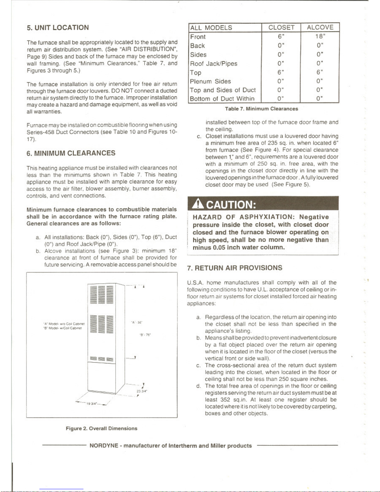
The lurnace shallbeappropnately located to the supply and
retum air dIstribution system. (See "AIR DISTRIBUTION".
Page9)Sides and backof the furnace maybeeoclosed
by
wall framing. (See "Minimum Clearances: Table7.and
Figures 3 through 5.)
The furnace installationisonly ,ntended for free air retum
Ihmugh the furnace door louvers. DO NOT connect a dueled
returna"sySlem directlytothe fumace. Improper installalion
may create a hazard and damage equIpment, as wellasvoid
all warranties.
Furnace maybe InstalledoncombustiblefloOring when
USing
5elles-458 Duct Connectors (see Table10and FIgures 10·
17).
6.
MINIMUM CLEARANCES
Th,s heat",," apphance mustbeInstalled
WIth
clearances
not
less than the minImUms shownInTable7.ThIS
heatIng
appliance mustbeInstalled
With
ample clearance
lor
easy
acceSStothe air lilter. blower assembly. burner assembly.
controls, and vent connections.
Minimum
furnace
clearancestocombustible
materialS
shallbeIn
accordance
with
Ihe
furnace
rallng
plate.
General clearances are as
follows:
a.
All IOstallat,ons; Back (0"), SIdes (0"). Top (6"), Duct
(0") and Roof Jack/Pipe (0")
b Alcove installations (see Ftgure
31:
minImum
18"
clearance at tront of turnace shall be provided lor
future sel\llcing. Aremovable accesspanel should be
III
ALL
MODELS
CLOSET
ALCOVE
Front
'"
""
Back
0"
0"
Sides
0"
0"
Roof
Jack/Pipes
0"
0"
Top
'"
'"
Plenum
Sides
0"
0"
Top
and
SidesofDuct
0"
0"
BottomofDUCI
WIthin
0"
0"
installed between top01the "..mace door
I'ame
and
the cell,ng
c. Closet installatIons
mUSI
use a Iouve'ed door
haVIng
a minImum free area of 235
sq,
on.
when Iocaled
S"
from fumace
l$a<>
Figure
4),
For
speCIal
clearance
between
1,"
and 6". reqUIrements are a louvered door
wllh a minimumof250 sq
,n
Iree a'ea.
With
the
openmgsInthe closet
Ooor
<mectlyinhne
wnh the
louveredopeOlngs
,n
thefurnacedoo' ,Afuliy louvered
c10sel
door mayoeuse<J
(Sa<>
Figure
51.
A CAUTION:
HAZARD
OF
ASPHYXIATION:
Negative
pressure
Inside
the
closet,
with
closet
door
closed
and
the
furnace
blower
operating
on
high
speed,
shall
be
no
more
negative
than
minus
0,05
Inch
water
column.
7.
RETURN AIR PROVISIONS
U.S.A. home manufactures shall comply W'lh ali of the
follOWIng
condilionsto have
U.L
acceptanceof ceilingorm·
floor return all systems for
clOSe!
Installed forced air heanng
appliances;
---
/
..
".
,
•
,,~
..
•
a Regardlessofthe location. the returnairopening mto
Ihe closet shall notbeleSS
lhan specliiedinlhe
appliance's I,stlng
b Meansshallbe provldedlOpreVenl lnadvenentclosure
by
a Ilat oblect placed ove' the returna"opening
whenItIS
located In Ihe lloor of Ihecloset (versus lhe
ven>eal
fronl or Side walil
c,
The cross"sechonal area01the relurn
dUCI
system
leading into the closet, when located in the floo,
Or
ceiling shall notbeless than 250 square ,nches.
d The total hee area ot open,ngs ,n the
Hoor
or ceiling
reglslersservingtne relurn airductsystem must be
at
least 352 sq.in.
AI
leasl one reglste, should
be
Iocaledwhereitisnotlikely
10becoveredby carpellng.
boxes and olhe,oblects,
Figure2.Ove",11
Dimensions
NORDYNE - manufaClUreroflntertherm
Bnd
Miller
products

e Materials located
,1'1
the
,,,'um duct system have a
llam<!
spread class,hcal,on ot
200
or
~SS,
f.
Noncombustible pans
havrng1"upturned flanges a,e
located beneath opefllngs
,1'1
a floor duct syslem,
g.
Wiring malerials located in
the
return duct system
shall conform10Art,,,le" 300-22Ofthe NatIOnal
Electrical Code (ANSI C1INFPA-701.
h.
Gas
pipingISnot
run,nOr
Ihroug"
the
relum
dOCI
system,
Test
lt1e
negative
pressu,e
Illlhe closet
wilh
the
air-
circulating fan operatingath'gh speed and the closet
close<'l,
The
negatove pressure
IS
10
be
no
more
negatIve than m,nus 0.05 ioch water column.
For floor return systems.
tile
manutaclured home
manufacturer shall all,. a prominent ma,l"ng on
or
nea, the appliance whereItCanbeeasily read when
the
closet doorisopen. The marketlng sllall 'ead:
HAZARDOFASPHYXIATION:
00
not cover
or
restrict return air opening.
A
CAUTION:
Three typical drslnbut,on
systems
are
illustrated mF,gure6,
For proper air dlstribuhOn, Ihe supply duel system musl be
deSigned so
lhallhe
slatlC pressure
measured
e~le,"al
to
the furnace
does
nol
exceeolhe
Iisteo
stallC
pressure
raling
shown
on
lhe furnace rahng plale.
8. AIR DISTRIBUTION
SYSTEMS
Locanon, size.
and
number01reg,sters shouldbeselec1ed
on the basisof
beSI
aor
distnl>u!Jon
and
floor planofIhe home.
.
_.
w.,
o·
,--
Figure3.Alcove Instalillion
0·
....
CIo"
to
F"
,.
o.-
,
figure4,Closet In.lallation
~
~----~--
"
~
~
~
:~~~:>".
ill
~
~
~
-<
r:'"
-""''''
~~~
"'''''''''
I
~~§
.-
>
02",
~~
~iiii~
r
~
~
iiii
~
(~S
~,
•
"'i'<''''
~:g,:§~
\.,
~i'<''''
"'~,...
II!
•
'-
"",a:
~
~L05E
~~
I,
,
"
[
flgur.6.Typical Supply
Duct
System
============~";O;;;";O;';";;;';~~m;;;.;";";'.;,;';":,rer
01
lnlerlherm
and
Miller
products.
_

9.
ROOF
JACK
SELECTION
,,-
This
;0<01
~'oo
above ceifing
Flashing
.!.ack
'-,.
,
111
/
/
C~vity
I
"~-
-
•
-,-
•
00
I
J
Furn"".
~-.
-
-'-
''''''
Ceding
Flal
Roo
Flue
PI~
CombuSl1
Air
Pipe
APPLICATION NOTES'
a.
FO, SO. SOT and FOT Senes Roof Jacks with a 5"
diameterinner vent pipe may be used with all models
ot
MG, MM. MS. andMBseries
gas and oillumaces,
b.
F_Flat, Flashing: Adjusts Irom
0112toat
least
1112
root slope
C,
S~Slant
Flashing tor
2.5112
Slope: adjusts
1112
to
41
12 root slope,
a Determ",e depth
ot
ceiling caVily trom
centel
of root
openlr>g
to center of ceiling opelllng, (See DimenSIon
"A"
in
Figure
7.)
b.
Determ",eceillngheight arid sublract height ottumace.
(See D,menslO/ls "B"
in
Figure 7.)
c.
AdddlmensOonsA+B (and Xfrom Table 9 and F'9ure
8 if stant deck flashing is used), The lotallength of
(A
+ B +X)Will
be
w~hin
the minimum and maximum
range of one of the Root Jacks
l>StedInTable 8.
Nole: Install only Root Jack Assemblies listedinTable 6
on
this Ileating appliance,
ROOF
JACK
EXTENSION
Figure
7. Rool Jack A
••
embfleo
Figure
8
~
"X"
(SEE
TABLE
~I
~
ROOf
JACK
SLANT DECK
FLASHING
ROOF
OPENING
CEILING
OPENING
CEILING
PITCHED
,~
ROOF
JACK
WITH
2',112
SLANT
FLASHING
Under some circumstances it maybedeSirable to raise the
Roof Jack by
USing
a furnace Root
lack
exlenslon (external
extensIOn pin 901937,IIIIernai extension pin 901935).
An
extenSIOn
or high
Wind
senes roof jack may helptosolve a
pilol outage caused by unusual wirld elleels because
of
geographICal features such as hiils. trees. tall buildings, etc
The extenSion
IS
availableas an opllonal accessoryand may
be purchased through your NQROYNE distributor.
,
I
,
MODEL
,
APPROX, ADJ.
NUMBER
LENGTHS'
BELOW FLASHING
F01323
-5
13- - 23-
F02343
-5
23" - 43"
501835
-5
18"-35"
502447
-5
24--47"
503253
-5 32" ·53"
504895
-5 48" - 95"
I
50T2442
-5
24"-42-
50T2745
-5 27" - 45"
50145B1
-5 45" - 81"
IFOT2846
-5
28" - 46-
2h
112
SLANT
DECK
SOT
~I
,
.....
."".....,
'"<L"''''_G
T"~T
""
0""'""
OT_
---
27
45
-5
L
6.7.;,",-
,...,TN
--
"'"GlN
5/12
ROOf
SLOPE
Tablee,Rool J..k A
....
mbl>e.
Fig~re
9.
NORDYNE -
manulacturer
ollntertherm
and
Miller
products
--------.
lop
0I5I4'PIY
Ulluel
(SH
Fogure
10)
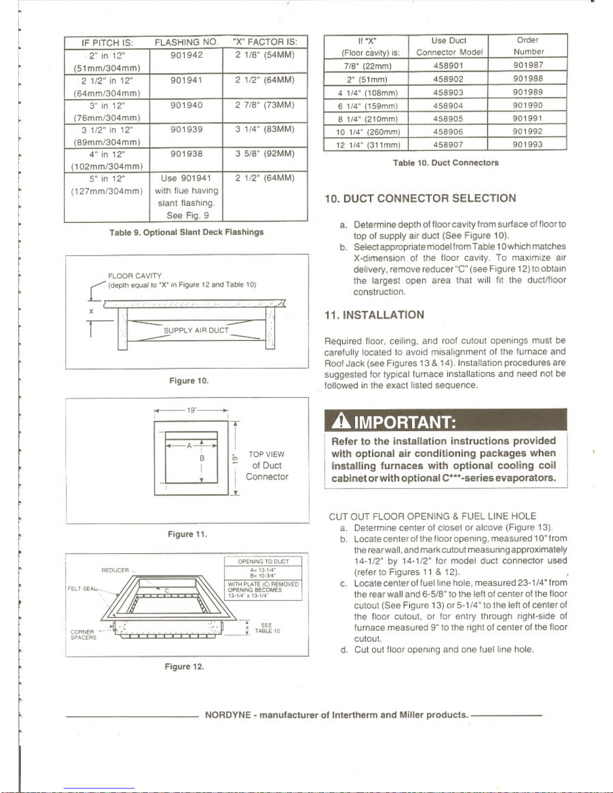
b.
Seled
appropniIlemodltlt<omTable 10wtw;:hma\C11e'5
X~
01
the lloof
caVl1y,
To maJOffille
a"
deIlvery.remtlIIe reducer"C"
(Me
F"ilure
12JIOoblam
lhe largest open area
tNI
WIll
lIt lhe duetnloor
conSlruc1lOR.
11.INSTAL.L.ATION
Required floor.
ceol,ng.
and loot
CulOu!
openongs
must
be
carefully located to
aVOid
m'sallgnmenlotrhe
lurnace
and
Rool Jack (sef! Figures
13&'4),
Installahon procedules a'e
suggested
lor
typlCallumace Inslallat,ons and
r.ee<:l
not
be
Tolowed in ,he exact IIs'ed
seO
....nce
Flgu..-,O.
R.00f'I
CAVITY
C
I
__
IO•X
...
F9n
'Z_T_'OI
1-1
2~""~oC=r
IF
~ITCH
IS
FLASHING
NO
.X" FACTOI'lIS'
..
,
UN
0ut:1
~,
2·InI:!'"
901942
21/8"
(54MMj
rFloo<
cav,M
is. ConnI<:lOr
MOGel
NumD~r
(51mm/304mm)
718"
122/Ml1
458~01
901987
2 112·
on
12·
90194,
2
112"
(~MM)
l'" 151/Ml)
453902
901988
{64mm/304mml
4
114·
(108mm\
458903
901989
3·
on
'2"
90,940
2
718"
(73MM)
6
114"
(\5!1r1m\
458904
901990
{76mml304mml
8 fl4"
(211;lmm1
458905
901\191
3 '12"
on
'2"
901939
3
114"
(83MM)
'A
,,..
(26Onwn)
.~~
9011192
(89""nI304mml
121(4·
1311"",,)
458907
901993
4"
on
12"
90\938
3 5/8"
(92/o1MJ
(lQ2rnm/J.04mml
T_
10.
Duel
Cor._lI:>n
S"on12'"
U
...
90194\
2
11'2"
(64MMJ
{127"""~"""1
WIth
......
MYIn'iJ
10. DUCT CONNECTOR SELECTION
"""
.....
.
""...Ell
'
a.
Del~dep(h
01Iloo<
cawytromsurlace
0I11oor1O
r
r
t
[
l
r
A IMPORTANT:
Reiertothe
inatallalion
Inalructlona
provided
with
optional
air
conditioning
packages when
Installing
furnaces
with
optional
cooling
coil
cablnetorwith
optional
C'"
"""es
evaporators.
_.-
.~.
Rgu..-l1.
"'''4'
•••
.........
1(0(:
"'l_
-_.
,,.,,
.
,,.
...
CUT
OUT
flOOR
OPENING
& FUEL LINE
HOlE
"'.
Det
.......
~e<
~
etoMt
Of
aJeQvoe (Fogure 1
J)
b Locatecenle<
~1helloorope<Wlg
.
..-sured
10" lrom
there.arwal!.andll'lllll<e>*llAmeasunngawoOXli,ralety
14-1/2" by
""1/2"
lor
r\""IOdII'I
d\lCI
co
..
...ao<
used
(<eter10FIgUf8S
11
&
12)
.
c.
Locateceote<01lue!
...
hole.
measured
23-1/4"
lrom
1I1e
rear will and
&-518"10
Ille
Ie/I
~
centerIII
tIE
IlDor
CUlout
(SH
Fogure
13)or5·114"
10
lhe
leh01<:ente'
III
me IIoor Culout.
or
IOf
efllry mrougtl ngM·SIde
01
furnace measurf(l 9"10rl'\f
.igt11
ot
~Ier
01
the
noor
culOul.
d
CUI
out
Hoor
QPe"'ng and
OI"H!!~
~ne
hole.
Figure
12.
- NORDVNE"
menllt.clur••ollntertherm
and
Miller
prodllcl
•.
_
..
_-'
...
-
...
.......
_-'"
~.-
b. GeI1lel'
ouct
connec1Of
.nd
pu$h
I)adl
.QalO'lSl
.ea.
edge
01
I'Ioor
opel
'"
og
C.
Mark CUlOIA
1oc:a1Kln
(tab
am)
and
rerTIOW! duel
,-
d_
Cut out duel
opetWlg
1!."
IiIrger tNln
....
marl<ed
.
flllu.a
16.0...
1Connector
,
I I
,
..
,.'
-_
........
--
~
.
~
.
-
•
•
-'
~
-
".
....
"
...
-
,
'0
"-
.
~-
•
_0
-0
•
"
...
..............
.-
..'".-.u.
01'
<LOS,,,""...
""""
.
I
..."""
.OHMIl
,
.""
DUC'
""""-
,
""-,
."".-
I
,
....
'-'
..
•
•
/N:'
,
-
-
•
<F<f~~
,
-
J"
...~,..'•.
~
,-
,
"""'"CI.~_
--
~-
•
~-
-
-
•
,
,
•
~
-
-------.-
'.
-----.-::
,
-
..-..
..........
--
•
•
Flgou" 13. Closet
0'
Ako
...
...
""
..1•.
Cul-Out
I
oc:_
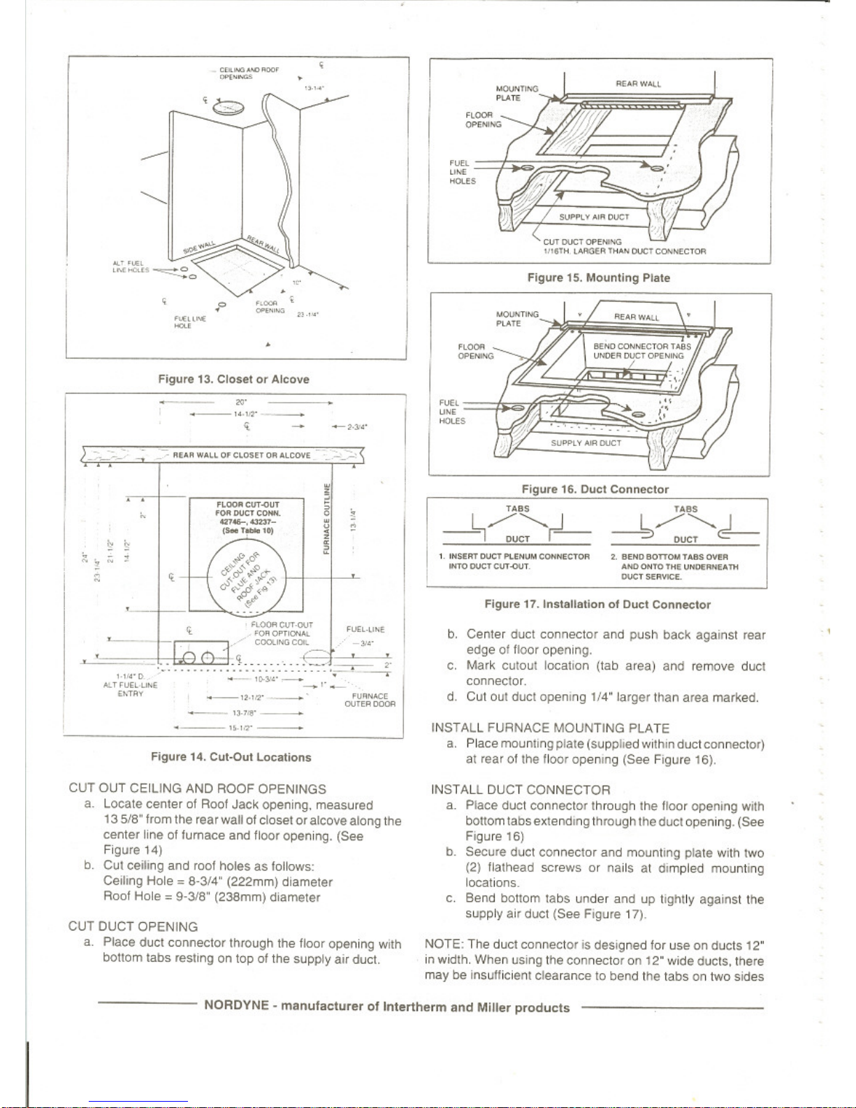
INSTALL FURNACE MOUNTING
ptA
TE
il-
Place
mounlIn§l
pa.
..
(S\lJlDlIed
W<Itwl
ouct
t<:A.."""""
ill
rear
ollhe
IIoor
opel-Ill
(See
Fogu.e 16).
ClIT
0lIT
CEILING AND ROOF OPENINGS
._ Lox.al.
<:enl.'
04
Roo!
Jack
openong.
measu
..
d
13
5/8"from
lhe
IU'
wd
04
dosel
CO"
~
8loog l1Ie
cen1et
"""
of
tumillCfl and
1100<
openong.
(See
Ff{j
.....
,.)
b
CUI
QeWlg
and
root
holes
as tallows,
CeUlg
Hole.
8·3/."
(222mml
d'amete'
Roo!
Hole.
g.3Jll" (238mm) d<ameter
CUT DUCT OPENING
a
P~c.
dUCl
connector through the floor opening
Wllh
bOnom
labs
'eSllng on topofthe
supply.It
duct.
INSTAll.
DUCT CONNECTOFl
..
Place duel connector lhrougll
lhe
IIoor
opel_ogWllh
bolIom
labs1!1Iendo:'lg
ll1fOo.1O/1lhe
ducl
~I
,"ig.
(See
Figure
15)
b Secure d...et conneclOf and mountmg plate
WIlh
two
(21
!lathead .crewso.nails aI (IImpled
mount"'9
locations
C Bend bonom labs
uode.
anduptlglltly
aQall1st
tile
SllPPly."
dUCI
(See
Figure 17)
NOTE,
Tile
d...et connecto.,s deSigned for use
on
ducts
12·
in
wJd1h.
When
USing
the connector
on
12" w,(le ducts, there
may be insuMicienl clearance to bend tne tabs
on
two s,aes
-------
NORDYNE -
manufaclur.r
ollnt.rlhe'm
and
Miller
p.oducts
•
•
INSTALL ROOF JACK
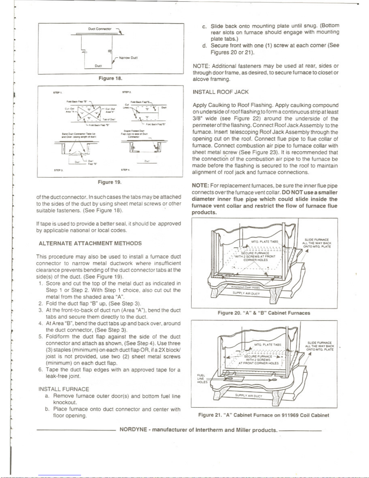
c Stide
bacl<
01'10
m:lOnli"ll
plale untit snug. (Bot1om
"'Ilr
stolS on
lumace
should e"<Jall€' with mount''''J
plate 18bs.)
d. Secure front with ooe (1) screw al
each
comer
(Set!
Figu,es
20
or
2t),
Apply Caulkmg to Roof FlashIng. Apply caUlkIng
compDl'n(!
on
Undersideofrootflashing,lDformacon\lnuousstnpatleasl
3/B" wKle
(see
Figure 22) around
the
unde""de
of the
penmelerofthe Hasnln9, Connect Rool
Jack
AssemblytoIhe
fumace.lnsell
telescop<ng
ROOf
Jack
Assemblylhrough
tile
opelll"ll
CUI
on the rool. Connect flue ll'Pl! 10 llue coHar
of
fumace, Connect combustIOn air
P<Pl!
to
lumac
.. collar with
sheet melal
SCrew
(See
Flgufe 23). II is rocommende<! that
the
connection of
the
combuSlIon
alf
p,pe to the Iurnace be
maoe
betore the flashIng is secUfeo to
tt>e
roof10maintain
alignment
01
roof jack and turnace COflIlllCIIOIlS.
NOTE: Addiloonallasteners
may
be
used
al
rear,
SlOeS
or
T1lfOUgh
(100<
frame.as(les"ect,10 secure
lurnace
tocloset
or
aICO"" framIng.
..
-
............
-",,-';."-;
...
\.\_'!"-
'
..
~-."",
---
'._'_.-
-
--v.R2,.t-
_
..
~
-'.
".'
'0"
_.
•
,"
-
......
---'-"
---_.-
u-~
~
r
f
Figure
1lI.
Olille
dllC1
conne<:lO'. In
such
CaseS too
tabs
maybeattached
to
the
sides
01
the
ductbyUSing
sheel
melal
screws
or other
sUitable
lasteners.
(SeeF'gure
18)
NOTE: Forreplacement lumaces,
bes"re
the
Innerllue
pipe
connects
overlhe
fumaceventcollar.00NOT
uae..amaller
diameler
inner
Ilue
pipe
Which
could
alid..inside
lhe
lurnace
vent
collar
and
reslricllhe
Ilow01lumac..lIue
producls.
FiGure
21.
"A"
Callin..t
Fum""
.. on
"196'
Coil Ceblnel
--
....'......
y'"""
'""OM",
"."
•
--
...'...w••
'"""
""toM'
.....
"
IIJI'
•
"'
....
.,,,-
-,.
~o~"~"'_
.,~~~
•
«_
'..-.co
~"',"""'ws
."
....
'
"""/:
""'
..
."-.-
...
C>
.
'"""
.-"0,,,,_,,,,
..._..
c..ooo_.
~.
"
~"""",,,WS
.,,""",
=-0._..
}
."
Figure
20.
-A"&-B"
Ceblnel Furn..:
..
It tapeIS
Use<110
provide a
bene'
seal.,tshouldbeapproved
by
applicable natKlOllIOflOCal
codes
Til,s procedure
may
also be used10,nstall a furnace
dUel
ccmnector 10 narrow
melal
dUClwor1<
whe'e
Insulh"",n1
c~a,ance
prevents bending
of
lhe
Que!
ccone<:IO'
tabs
at the
sKleis)
01
the
duct
(See
F'!lure 19)
1 SCore
and
Cui the top
01
the
metal
ductasIndICated
,n
Slep'
or
Step 2. With Slep ,
chOICe.
also cut
001
the
melal from the shaded
a,ea
"A"
2 Fold the duct
Hap
-go
up.
(See
Step 3l
3.
At the
fronHp·Di!ckofdUCI
run
(Area
"A"),
oer>d
the
dUCI
labs
and
secUfe u
....md<re<:lly
to
the
duel
4AtArea"S",
bend
the dUCl1abs up
an<!
back
o"e"
around
'he
duct
connectO'.lSet!
Step 3),
5.
Foict/lorm the
duel
flap
a'1a"ut
the
sode
ot the duet
COMedO,
an<!
attach as
s!>Own,
(Set! Step 4). Use Ih,,,,,
(3) staples(mlnomum)oneachduct flap OR.
~
a2Xblock/
""stis1101
p<0\fItIe<l. use two (2) Sr.eel metal screws
(minImum) on each
duct
llap.
6.
Tape
the duel flap edges
With
an approved tape tor a
leak·f,ee
jomt
ALTERNATE
ATTACHMENT
METHODS
INSTALL FURNACE
a. Remove furnace
oute,
doorlsj
an<!
b<:1lI0m
tvet tIne
knockout
b,
Place fumace onlO duct connectO' and center
w~h
floo, opening
NORDYNE·
manufactu,eroftnlertf\erm
and
Millar
producls.
_
 Loading...