

Page 1
Nordson Corporation
OPERATOR CARD
P/N 187695-03
Manual Iso-Flor HD and VC Voltage Block Systems
Safety
WARNING: Operating the system with more
than one spray device connected to it may be
unsafe and in violation of National Fire
Prevention Association (NFPA) regulations.
It also voids the warranty. If this occurs,
Nordson Corporation will not be responsible
for the performance or life of the system.
WARNING: Allow only qualified personnel to
perform the following tasks. Follow the
safety instructions in this document and all
other related documentation.
WARNING: Risk of electrical shock. Shut off
the electrostatic voltage before opening the
cabinet door. Failure to observe this warning
could result in personal injury, death, or
equipment damage.
WARNING: Make sure the room where you
are working is sufficiently ventilated during
the flushing procedure. Avoid breathing
vapors over prolonged periods of time.
WARNING: Ground all electrically
conductive equipment in the spray area.
Check the Iso-Flo cabinet ground. Make
sure all internal and external connections are
clean and secure. Ungrounded conductive
equipment can store a static charge which
could ignite a fire or cause an explosion if a
hot spark is discharged.
CAUTION: Failure to use a compatible
cleaning solution could cause equipment
damage or fluid contamination.
To use this equipment safely,
S follow the instructions in this operator’s card and
the referenced manuals.
S obtain and read the Material Safety Data Sheets
for all materials used.
Introduction
This operator’s card contains basic information
necessary for daily operations. For other information,
refer to the product manual.
The procedures and figures in this document can
vary depending on your system setup, safety
regulations, and system requirements.
1
Page 2
Startup
Operation
The startup procedure assumes the system was left
full of coating material after the last shutdown. For
daily startup, see Figure 1 and do the following:
1. Make sure the electrostatic voltage is off.
2. Turn on compressed air to the Iso-Flo system (5).
Verify that the setting is 5−8 bar (80−120 psi).
3. Turn on the fluid inlet pressure. Verify that the
setting is 5−10.3 bar (80−150 psi).
4. Turn on the electrostatic voltage. Verify that the
setting is 60 kV or less.
Refer to Operation for the procedures to follow to
begin spraying.
1
2
3
4
See Figure 1. Squeezing the trigger on the spray
device (1) activates the Iso-Flo system and spraying
can begin. Before spraying, check the fluid pressure,
atomizing air, and fan pattern and adjust as needed.
NOTE: The Iso-Flo system supplies about 40 oz of
coating material continuously. In most situations
there are enough pauses between parts to allow the
system to refill itself. If your operation does not
provide these pauses, release the trigger on the
spray device completely for 5−15 seconds. Do this
every 2−5 minutes (depending on the spray gun flow
rate).
NOTE: For Iso-Flo VC system, the supply volume
can be adjusted to less than the full 40 oz capacity.
Fluid Pressure Adjustment
To adjust the fluid output pressure and flow rate, see
Figure 1 and do the following:
1. Turn the fluid pressure adjustment knob (4) in
small increments.
2. Squeeze the trigger on the spray device (1) and
check the spray pattern. Continue adjusting the
pressure as needed.
NOTE: The fluid pressure should be 0.7−2.1 bar
(10−30 psi). If you reach a setting outside of this
range, try selecting a different fluid tip size. For
details on selecting a fluid tip, refer to the instructions
provided with your spray gun.
5
6
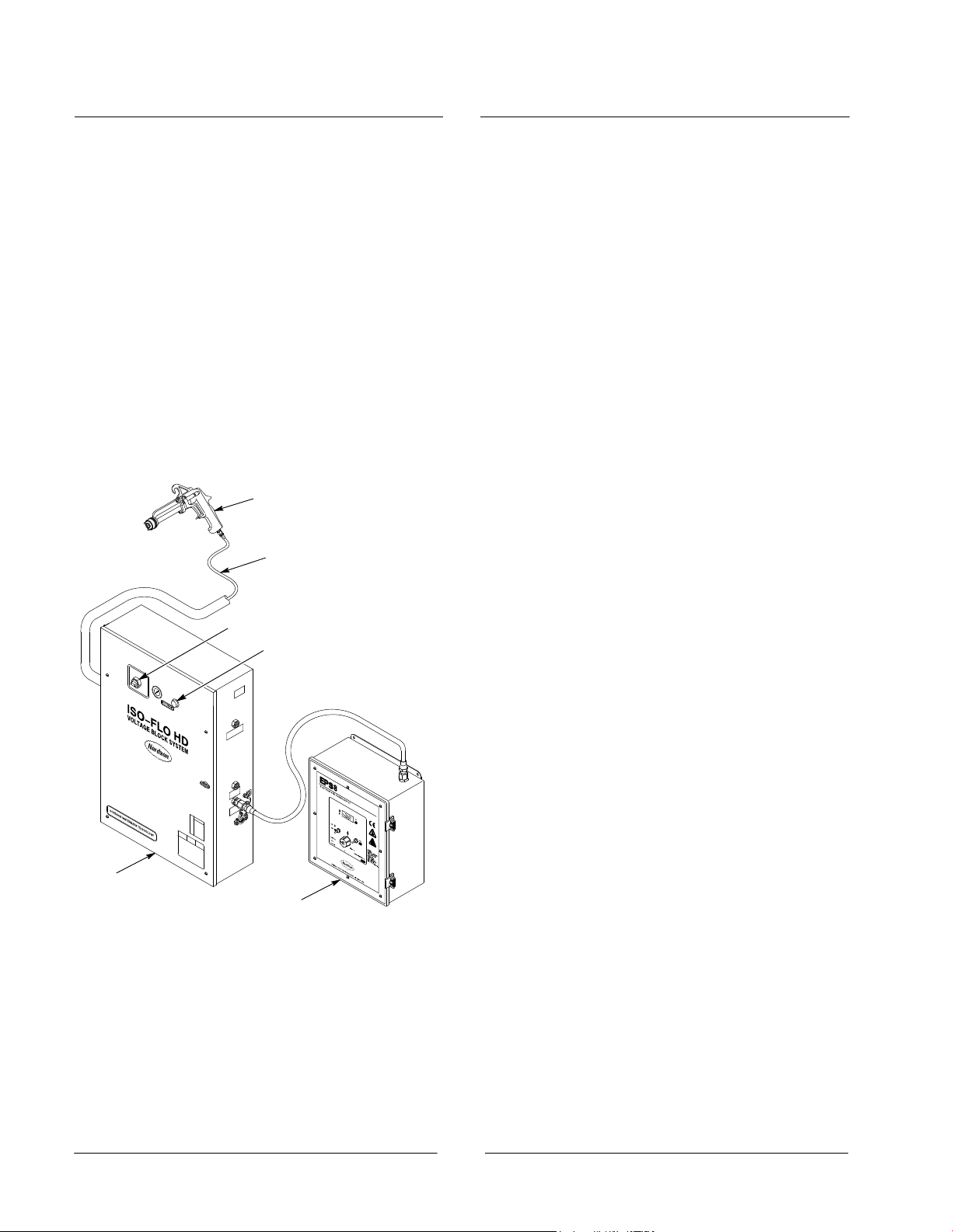
Figure 1 Basic System Components
1. Spray device
2. Fluid hose
3. Toggle valve
4. Fluid pressure adjustment knob
5. Iso-Flo HD system
6. Electrostatic power supply
Atomizing Air Adjustment
Use the externally supplied air regulator to adjust the
atomizing air until you achieve the required
atomization. To maximize electrostatics, select the
lowest possible pressure at which you can achieve
good atomization.
1300374A
NOTE: The atomizing air setting should be
2.1−3.5 bar (30−50 psi). Electrostatics will not
activate below 2.1 bar (30 psi).
Fan Pattern Adjustment
Refer to the instructions provided with your spray gun
for information on adjusting the fan pattern.
2
Page 3

Shutdown
NOTE: Coating materials containing solids that do
not settle out quickly may be left in the system
overnight. Flush all system components when the
system is out of service for more than 24 hours or
when using coating materials containing solids that
settle out.
Short-Term
For short-term shutdown, see Figure 1 and follow
these steps:
1. Shut off electrostatic voltage to the system.
2. Shut off compressed air to the system.
3. Shut off the fluid supply to the system.
4. Squeeze the trigger on the spray device (1) to
relieve compressed air pressure.
5. Open the cabinet door. Move the shuttle to
manually separate the couplings.
6. Clean the male and female couplings with a
compatible cleaning solution.
7. Close the cabinet door.
Long-Term
To shut down the system for an extended period,
follow these steps:
1. Shut off electrostatic voltage to the system.
2. Flush the system with compatible cleaning
solution, following steps 1−5 in Changing Coating
Material or Cleaning the System.
3. Open the cabinet door. Move the shuttle to
manually separate the couplings.
4. Clean the male and female couplings and the
interior and exterior of the cabinet and its
components with a compatible cleaning solution.
5. Close the cabinet door.
Changing Coating Material or Cleaning the System
To change coating material or clean the system, see
Figure 1 and do the following:
1. Shut off electrostatic voltage to the system.
2. Shut off the fluid supply to the system.
3. Hold the toggle valve (3) in the EMPTY position
and trigger the spray device (1) into the spray
booth or a grounded waste container to expel any
remaining coating material.
4. Supply cleaning solution to the Iso-Flo system (5)
through the fluid input supply.
5. Hold the toggle valve (3) in the EMPTY position
and trigger the spray device (1) into the spray
booth or a grounded waste container. This
flushes the system pump, hose, and spray
device. Continue until the cleaning solution and
any remaining air are eliminated.
6. Replace the cleaning solution with new coating
material. Hold the toggle valve (3) in the EMPTY
position and trigger the spray device (1) into the
spray booth or a grounded waste container.
Continue until the coating material purges any
remaining cleaning solution from the system.
7. Release the spray device (1) trigger and the
toggle valve (3). The new coating material enters
the system.
Iso-Flo VC: Settings and Adjusting Volume Control
Refer to the Iso-Flo VC System manual (part number
1606746) for procedure.
3
Page 4

Maintenance
The following procedures describe the maintenance
required to keep the system operating at its
maximum efficiency.
Daily
1. Shut off electrostatic voltage to the system.
2. Shut off compressed air to the system.
3. Shut off the fluid supply to the system.
4. Squeeze the trigger on the spray device to relieve
compressed air pressure.
5. Open the cabinet door. Move the shuttle to
manually separate the couplings.
6. Clean the male and female couplings with a
compatible cleaning solution to prevent coating
material buildup.
7. Apply a small amount of compatible lubricant to
both couplings. This will keep the coating
material from sticking and will facilitate cleanup.
8. Close the cabinet door.
Weekly
1. Shut off electrostatic voltage to the system.
2. Shut off compressed air to the system.
4. Squeeze the trigger on the spray device to relieve
compressed air pressure.
5. Flush the system with a compatible cleaning
solution, as needed, following steps 1−5 in
Changing Coating Material or Cleaning the
System.
6. Open the cabinet door. Move the shuttle to
manually separate the couplings.
7. Clean the male and female couplings with a
compatible cleaning solution. Lightly coat the
female coupling shafts with O-ring grease. Use a
stiff brush to work the grease through the spring.
8. The lubrication cup is located on the front of the
pump. Unscrew the plug on the top of the
lubrication cup and add
diluted Q-solvent to the cup.
NOTE: Fill the lubrication cup to the bottom of its
vent hole. This will equal the
diluted Q-solvent that is needed.
9. If your Iso-Flo unit is not equipped with an air
lubricator, remove the air supply hose and add
5−10 drops of lightweight valve oil into the
1
/4-in. NPT fitting labeled COMPRESSED AIR on
the side of the unit.
1
/2 ounce of properly
1
/2 ounce of properly
3. Shut off the fluid supply to the system.
Original copyright date 1997. Iso-Flo, Nordson, and the Nordson logo are registered trademarks of Nordson Corporation.
10. Close the cabinet door.
Issued 04/15
4
 Loading...