


Control System CS 20
for MX / MC Hot Melt Material Applicators
Manual P/N 412 960 D
± English ±
NORDSON ENGINEERING GMBH LÜNEBURG GERMANY

Note
This manual applies to MX/MC units with CS 20 central units with the following P/N:
P/N 448 513
P/N 449 507
P/N 449 485
P/N 449 509
Order number
P/N = Order number for Nordson products
Notice
This is a Nordson Corporation publication which is protected by copyright. Original copyright date 1999.
No part of this document may be photocopied, reproduced, or translated to another language without the prior written consent of Nordson Corporation. The information contained in this publication is subject to change without notice.
Trademarks
AccuJet, AquaGuard, Asymtek, Automove, Autotech, Blue Box, CF, CanWorks, Century, Clean Coat, CleanSleeve, CleanSpray, Compumelt, Control Coat, Cross-Cut, Cyclo-Kinetic, Dispensejet, DispenseMate, Durafiber, Durasystem, Easy Coat, Easymove Plus, Econo-Coat, EPREG, ETI, Excel 2000, Flex-O-Coat, FlexiCoat,Flexi-Spray, Flow Sentry, Fluidmove, FoamMelt, FoamMix, Helix, Horizon, Hose Mole, Hot Shot, Hot Stitch, Isocoil, Isocore, Iso-Flo, JR, KB30, Little Squirt, Magnastatic, MEG, Meltex, MicroSet, Millenium, Mini Squirt, Moist-Cure, Mountaingate, MultiScan, Nordson, OmniScan, Opticoat, Package of Values, Pattern View, PluraFoam, Porous Coat, PowderGrid, Powderware, Pro-Flo, ProLink, Pro-Meter, Pro-Stream, PRX, RBX, Rhino, S. design stylized, Saturn, SC5, Select Charge, Select Coat, Select Cure, Slautterback, Smart-Coat, Spray Squirt, Spraymelt, Super Squirt, Sure Coat, System Sentry, Tela-Therm, Trends, Tribomatic, UniScan, UpTime, Veritec, Versa-Coat, Versa-Screen, Versa-Spray, Watermark, When you expect more. are registered trademarks ± ± of Nordson Corporation.
ATS, Aerocharge, Auto-Flo, AutoScan, BetterBook, Chameleon, CanNeck, Check Mate, COLORMAX, Control Weave, Controlled Fiberization, CPX, E-Nordson, EasyClean, Eclipse, Equi=Bead, Fillmaster, Gluie, Ink-Dot, Iso-Flex, Kinetix, Maxima, MicroFin, Minimeter, Multifil, OptiMix, PluraMix, Primarc, Prism, Process Sentry, PurTech, Pulse Spray, Seal Sentry, Select Series, Sensomatic, Shaftshield, Spectral, Spectrum, Sure Brand, Swirl Coat, Vista, Walcom, 2 Rings (Design) are trademarks ± T ± of Nordson Corporation.
Designations and trademarks stated in this document may be brands that, when used by third parties for their own purposes, could lead to violation of the owners' rights.
COV_EN_412960D |
CS03 |
|
Issued 07/01 |
E 2001 Nordson Corporation
All rights reserved

Table of Contents |
I |
Table of Contents
Overview
1. Safety . . . . . . . . . . . . . . . . . . . . . . . . . . . . . . . . . . . . . . . . . . . . . . . . . . . . . 1 2. Intended Use . . . . . . . . . . . . . . . . . . . . . . . . . . . . . . . . . . . . . . . . . . . . . . . 1 Unintended Use . . . . . . . . . . . . . . . . . . . . . . . . . . . . . . . . . . . . . . . . . . 1 Residual Risks . . . . . . . . . . . . . . . . . . . . . . . . . . . . . . . . . . . . . . . . . . . 1 3. Note on Manual . . . . . . . . . . . . . . . . . . . . . . . . . . . . . . . . . . . . . . . . . . . . . 1
4. PROFIBUS DP . . . . . . . . . . . . . . . . . . . . . . . . . . . . . . . . . . . . . . . . . . . . . 2
General Information . . . . . . . . . . . . . . . . . . . . . . . . . . . . . . . . . . . . . . . 2
Plug Connectors . . . . . . . . . . . . . . . . . . . . . . . . . . . . . . . . . . . . . . . . . . 2
Installation . . . . . . . . . . . . . . . . . . . . . . . . . . . . . . . . . . . . . . . . . . . . . . . 2
Transmission Speed . . . . . . . . . . . . . . . . . . . . . . . . . . . . . . . . . . . . . . 3
Guidelines . . . . . . . . . . . . . . . . . . . . . . . . . . . . . . . . . . . . . . . . . . . . . . . 3
Host . . . . . . . . . . . . . . . . . . . . . . . . . . . . . . . . . . . . . . . . . . . . . . . . . . 3
Definition of Terms . . . . . . . . . . . . . . . . . . . . . . . . . . . . . . . . . . . . . . . . 3
Stand Alone Mode . . . . . . . . . . . . . . . . . . . . . . . . . . . . . . . . . . . . . . 3
Remote Mode . . . . . . . . . . . . . . . . . . . . . . . . . . . . . . . . . . . . . . . . . . 3
5. Control Panel . . . . . . . . . . . . . . . . . . . . . . . . . . . . . . . . . . . . . . . . . . . . . . . 4 6. Control Panel for Double Stream Pumps . . . . . . . . . . . . . . . . . . . . . . . 5 7. Indication Lamps and Indicator Beacon . . . . . . . . . . . . . . . . . . . . . . . . 6 8. Overview of Settings . . . . . . . . . . . . . . . . . . . . . . . . . . . . . . . . . . . . . . . . . 7 Temperature Part . . . . . . . . . . . . . . . . . . . . . . . . . . . . . . . . . . . . . . . . . 7 Motor Part . . . . . . . . . . . . . . . . . . . . . . . . . . . . . . . . . . . . . . . . . . . . . . . 8
E 2001 Nordson Corporation All rights reserved
CS03 |
P/N 412960D |
Issued 07/01 |
|

II Table of Contents
Operating the Temperature
Part
1. Operation Overview . . . . . . . . . . . . . . . . . . . . . . . . . . . . . . . . . . . . . . . . 11 2. Display Overview . . . . . . . . . . . . . . . . . . . . . . . . . . . . . . . . . . . . . . . . . . . 12 Overview of Parameters Set by Channel . . . . . . . . . . . . . . . . . . . . 13 3. Basic Settings . . . . . . . . . . . . . . . . . . . . . . . . . . . . . . . . . . . . . . . . . . . . . 14 Startup Control with Leading Channel . . . . . . . . . . . . . . . . . . . . . . 14 Temperature Display, Selecting Celsius or Fahrenheit . . . . . . . . 14 Switching Scan Mode On/Off . . . . . . . . . . . . . . . . . . . . . . . . . . . . . . 14 Selecting Control or Measuring Mode . . . . . . . . . . . . . . . . . . . . . . . 15 Switching Channel On/Off . . . . . . . . . . . . . . . . . . . . . . . . . . . . . . . . . 15
4. Switching Immediate Temperature Setback On/Off . . . . . . . . . . . . . 16 5. Setting Temperature . . . . . . . . . . . . . . . . . . . . . . . . . . . . . . . . . . . . . . . . 16 6. Setting Parameters . . . . . . . . . . . . . . . . . . . . . . . . . . . . . . . . . . . . . . . . . 17 Setting Parameters by Channel . . . . . . . . . . . . . . . . . . . . . . . . . . . . 17 Example of Selecting Parameter Set . . . . . . . . . . . . . . . . . . . . . 17 Return Parameter to Factory Setting . . . . . . . . . . . . . . . . . . . . . . . 17 Parameter Overview . . . . . . . . . . . . . . . . . . . . . . . . . . . . . . . . . . . . . 18 SPL = Setback Temperature . . . . . . . . . . . . . . . . . . . . . . . . . . . . 18 h SPL = Setback Period . . . . . . . . . . . . . . . . . . . . . . . . . . . . . . . 18 Co OFF = Inert Gas Interval . . . . . . . . . . . . . . . . . . . . . . . . . . . . 18 Co On = Inert Gas Injection Period . . . . . . . . . . . . . . . . . . . . . . . 18 t1 = Control Mode . . . . . . . . . . . . . . . . . . . . . . . . . . . . . . . . . . . . . 18 Lo = Undertemperature Value/Interlock . . . . . . . . . . . . . . . . . . . 19 Hi = Overtemperature Value . . . . . . . . . . . . . . . . . . . . . . . . . . . . 19 OFF = Overtemperature Shutdown . . . . . . . . . . . . . . . . . . . . . . 19 Pid = Predefined Control Parameters . . . . . . . . . . . . . . . . . . . . 19 On = Regulation Ratio (Display) . . . . . . . . . . . . . . . . . . . . . . . . . 20 SE = Service Display . . . . . . . . . . . . . . . . . . . . . . . . . . . . . . . . . . . 20
7. Automatic Fault Displays . . . . . . . . . . . . . . . . . . . . . . . . . . . . . . . . . . . . 20
8. Bar Graph (Option) . . . . . . . . . . . . . . . . . . . . . . . . . . . . . . . . . . . . . . . . . 22
P/N 412960D |
CS03 |
|
Issued 07/01 |
E 2001 Nordson Corporation
All rights reserved

Table of Contents |
III |
Operating the Motor Part
1. Operation Overview . . . . . . . . . . . . . . . . . . . . . . . . . . . . . . . . . . . . . . . . 24
2. Display Overview . . . . . . . . . . . . . . . . . . . . . . . . . . . . . . . . . . . . . . . . . . . 25
3. Pressure Control . . . . . . . . . . . . . . . . . . . . . . . . . . . . . . . . . . . . . . . . . . . 27
4. Basic Settings . . . . . . . . . . . . . . . . . . . . . . . . . . . . . . . . . . . . . . . . . . . . . 28
Selecting Manual or Automatic Mode . . . . . . . . . . . . . . . . . . . . . . . 28
Selecting Pressure Display (Option) bar or psi . . . . . . . . . . . . . . . 28
5. Test . . . . . . . . . . . . . . . . . . . . . . . . . . . . . . . . . . . . . . . . . . . . . . . . . . . . . . 29
6. Switching ON Motor(s) . . . . . . . . . . . . . . . . . . . . . . . . . . . . . . . . . . . . . . 29
Motor Startup Protection . . . . . . . . . . . . . . . . . . . . . . . . . . . . . . . . . . 29
7. Switching OFF Motor(s) . . . . . . . . . . . . . . . . . . . . . . . . . . . . . . . . . . . . . 30
Switch Off one Motor . . . . . . . . . . . . . . . . . . . . . . . . . . . . . . . . . . . . . 30
Switch Off all Motors . . . . . . . . . . . . . . . . . . . . . . . . . . . . . . . . . . . . . 30
8. Set Speed (Manual Mode) . . . . . . . . . . . . . . . . . . . . . . . . . . . . . . . . . . . 30 9. Setting Speed (Automatic Mode) . . . . . . . . . . . . . . . . . . . . . . . . . . . . . 31 Speed Parameters in Automatic Mode . . . . . . . . . . . . . . . . . . . . . . 31 10. Switching Automatic Temperature Setback ON/OFF . . . . . . . . . . . . 33
11. Setting Parameters . . . . . . . . . . . . . . . . . . . . . . . . . . . . . . . . . . . . . . . . . 33 Return Parameter to Factory Setting . . . . . . . . . . . . . . . . . . . . . . . 33 Parameter Overview . . . . . . . . . . . . . . . . . . . . . . . . . . . . . . . . . . . . . 34 rLo = Motor Speed at 0 % Pilot Voltage . . . . . . . . . . . . . . . . . . . 34 rhi = Motor Speed at Pilot Voltage Uhi . . . . . . . . . . . . . . . . . . . . 34
Uhi = Pilot Voltage
at which the Motor Rotates Constantly at rhi . . . . . . . . . . . . . . 34 rLo, rhi and Uhi, Graphic Illustration . . . . . . . . . . . . . . . . . . . . . . 34 PSH = Pressure at Pilot Voltage Uhi . . . . . . . . . . . . . . . . . . . . . 35 PSL = Pressure at 0 % Pilot Voltage . . . . . . . . . . . . . . . . . . . . . 35 PSP = Pressure Setpoint (Manual Mode) . . . . . . . . . . . . . . . . . 35 PSL, PSH and Uhi, Graphic Illustration . . . . . . . . . . . . . . . . . . . 35
PAH = Pressure Monitoring
for Overpressure (when Pressure Controlled) . . . . . . . . . . . . . 36
PAL = Pressure Monitoring
for Underpressure (when Pressure Controlled) . . . . . . . . . . . . 36
E 2001 Nordson Corporation All rights reserved
CS03 |
P/N 412960D |
Issued 07/01 |
|

IV Table of Contents
Operating the Motor Part
(contd.)
SPL = Temperature Setback after Motor Standstill . . . . . . . . . 36 PdS = Second Display for Double Stream Pumps . . . . . . . . . . 36 PrS = Variable Pressure Measuring Range . . . . . . . . . . . . . . . 37 Plo = Pressure Monitoring for Underpressure . . . . . . . . . . . . . 37 Phi = Pressure Monitoring for Overpressure . . . . . . . . . . . . . . . 37 SLo = Threshold Value Switch, Lower Value . . . . . . . . . . . . . . 38 Shi = Threshold Value Switch, Upper Value . . . . . . . . . . . . . . . 38 SLo and Shi, Graphic Illustration . . . . . . . . . . . . . . . . . . . . . . . . . 38 drS = Reverse Speed . . . . . . . . . . . . . . . . . . . . . . . . . . . . . . . . . . 38 drt = Reverse Time . . . . . . . . . . . . . . . . . . . . . . . . . . . . . . . . . . . . 38 rPU = Adapting Speed to Special Gearbox . . . . . . . . . . . . . . . . 39 r_d = Limiting Value for Speed Alarm . . . . . . . . . . . . . . . . . . . . . 39 Adr = Field Bus Address of Unit . . . . . . . . . . . . . . . . . . . . . . . . . 39 CoF = Inert Gas Control (Interval) . . . . . . . . . . . . . . . . . . . . . . . 40 Con = Inert Gas Control (Injection Period) . . . . . . . . . . . . . . . . 40 C1 = Forcibly Actuated Inert Gas Injection . . . . . . . . . . . . . . . . 40 C2 = Forcibly Actuated Air Exhaust (Vacuum Pump) . . . . . . . 40
12. Service Displays . . . . . . . . . . . . . . . . . . . . . . . . . . . . . . . . . . . . . . . . . . . 41
Service Displays di and do . . . . . . . . . . . . . . . . . . . . . . . . . . . . . . . . 43
Code of DIP Switch S 6 . . . . . . . . . . . . . . . . . . . . . . . . . . . . . . . . . . . 43
Service Display Error . . . . . . . . . . . . . . . . . . . . . . . . . . . . . . . . . . . . . 44
P/N 412960D |
CS03 |
|
Issued 07/01 |
E 2001 Nordson Corporation
All rights reserved

Table of Contents |
V |
Technical Appendix of the
Temperature Part
1. Diagnosis Program . . . . . . . . . . . . . . . . . . . . . . . . . . . . . . . . . . . . . . . . . 51 Activating the Diagnosis Program . . . . . . . . . . . . . . . . . . . . . . . . . . 52 Test phase 0 . . . . . . . . . . . . . . . . . . . . . . . . . . . . . . . . . . . . . . . . . . . . 52 Test Phases 1 to n . . . . . . . . . . . . . . . . . . . . . . . . . . . . . . . . . . . . . . . 53 Ending the Diagnosis Program . . . . . . . . . . . . . . . . . . . . . . . . . . . . 54
2. Correcting Temperature Sensors . . . . . . . . . . . . . . . . . . . . . . . . . . . . . 54
3. Temperature Control Panel Board . . . . . . . . . . . . . . . . . . . . . . . . . . . . 55
Fuses . . . . . . . . . . . . . . . . . . . . . . . . . . . . . . . . . . . . . . . . . . . . . . . . . . 55
LED's . . . . . . . . . . . . . . . . . . . . . . . . . . . . . . . . . . . . . . . . . . . . . . . . . . 55
DIP Switch S 7 . . . . . . . . . . . . . . . . . . . . . . . . . . . . . . . . . . . . . . . . . . 56
DIP Switch S 8 . . . . . . . . . . . . . . . . . . . . . . . . . . . . . . . . . . . . . . . . . . 56
DIP Switch S 8, Switch 6 . . . . . . . . . . . . . . . . . . . . . . . . . . . . . . . . . . 57
Plug Connectors . . . . . . . . . . . . . . . . . . . . . . . . . . . . . . . . . . . . . . . . . 57
4. Temperature Control Module . . . . . . . . . . . . . . . . . . . . . . . . . . . . . . . . . 58
Fe-CuNi . . . . . . . . . . . . . . . . . . . . . . . . . . . . . . . . . . . . . . . . . . . . . . . . 58
Pt 100, Ni 120 . . . . . . . . . . . . . . . . . . . . . . . . . . . . . . . . . . . . . . . . . . . 59
LED's . . . . . . . . . . . . . . . . . . . . . . . . . . . . . . . . . . . . . . . . . . . . . . . . . . 60
Plug Connectors . . . . . . . . . . . . . . . . . . . . . . . . . . . . . . . . . . . . . . . . . 61
Selector Switch S 1 . . . . . . . . . . . . . . . . . . . . . . . . . . . . . . . . . . . . . . 62
DIP Switch S 2 . . . . . . . . . . . . . . . . . . . . . . . . . . . . . . . . . . . . . . . . . . 62
DIP Switch S 3 . . . . . . . . . . . . . . . . . . . . . . . . . . . . . . . . . . . . . . . . . . 62
Potentiometer P 1 . . . . . . . . . . . . . . . . . . . . . . . . . . . . . . . . . . . . . . . . 62
Switch S . . . . . . . . . . . . . . . . . . . . . . . . . . . . . . . . . . . . . . . . . . . . . . . . 62
5. Voltage Control of Temperature Control Module . . . . . . . . . . . . . . . . 63
Fuses . . . . . . . . . . . . . . . . . . . . . . . . . . . . . . . . . . . . . . . . . . . . . . . . . . 63
LED's . . . . . . . . . . . . . . . . . . . . . . . . . . . . . . . . . . . . . . . . . . . . . . . . . . 63
Plug Connectors . . . . . . . . . . . . . . . . . . . . . . . . . . . . . . . . . . . . . . . . . 63
E 2001 Nordson Corporation All rights reserved
CS03 |
P/N 412960D |
Issued 07/01 |
|

VI Table of Contents
Technical Appendix of the
Temperature Part (contd.)
6. |
Bar Graph (Option) . . . . . . . . . . . . . . . . . . . . . . . . . . . . . . . . . . . . . . . . . |
64 |
|
Fuses . . . . . . . . . . . . . . . . . . . . . . . . . . . . . . . . . . . . . . . . . . . . . . . . . . |
64 |
|
LED's . . . . . . . . . . . . . . . . . . . . . . . . . . . . . . . . . . . . . . . . . . . . . . . . . . |
64 |
|
Plug Connectors . . . . . . . . . . . . . . . . . . . . . . . . . . . . . . . . . . . . . . . . . |
65 |
|
Selector Switch S 2 . . . . . . . . . . . . . . . . . . . . . . . . . . . . . . . . . . . . . . |
65 |
|
DIP Switch S 1 . . . . . . . . . . . . . . . . . . . . . . . . . . . . . . . . . . . . . . . . . . |
65 |
|
DIP Switch S 3 . . . . . . . . . . . . . . . . . . . . . . . . . . . . . . . . . . . . . . . . . . |
66 |
|
Basic Settings (Switches 1 and 2) . . . . . . . . . . . . . . . . . . . . . . . |
66 |
|
Setting Deviation Values (Switches 3 to 8) . . . . . . . . . . . . . . . . |
66 |
7. |
Temperature Comparison Measuring Point . . . . . . . . . . . . . . . . . . . . |
67 |
P/N 412960D |
CS03 |
|
Issued 07/01 |
E 2001 Nordson Corporation
All rights reserved

Table of Contents |
VII |
Technical Appendix of the
Motor Part
1. Central Module with Digital Input/Output . . . . . . . . . . . . . . . . . . . . . . . 69 2. Central Module . . . . . . . . . . . . . . . . . . . . . . . . . . . . . . . . . . . . . . . . . . . . 69 Fuses . . . . . . . . . . . . . . . . . . . . . . . . . . . . . . . . . . . . . . . . . . . . . . . . . . 69 LED's . . . . . . . . . . . . . . . . . . . . . . . . . . . . . . . . . . . . . . . . . . . . . . . . . . 70 Potentiometer R 18, R 42 . . . . . . . . . . . . . . . . . . . . . . . . . . . . . . . . . 70 DIP Switch S 1 . . . . . . . . . . . . . . . . . . . . . . . . . . . . . . . . . . . . . . . . . . 70 DIP Switch S 6 . . . . . . . . . . . . . . . . . . . . . . . . . . . . . . . . . . . . . . . . . . 71 Button S 3 . . . . . . . . . . . . . . . . . . . . . . . . . . . . . . . . . . . . . . . . . . . . . . 71 Switch S 2 . . . . . . . . . . . . . . . . . . . . . . . . . . . . . . . . . . . . . . . . . . . . . . 71 Switch S 15 . . . . . . . . . . . . . . . . . . . . . . . . . . . . . . . . . . . . . . . . . . . . . 71 Plug Connectors . . . . . . . . . . . . . . . . . . . . . . . . . . . . . . . . . . . . . . . . . 72 Aligning Pilot Voltage . . . . . . . . . . . . . . . . . . . . . . . . . . . . . . . . . . . . . 74 Aligning Pilot Voltage Input 0 to 10 VDC . . . . . . . . . . . . . . . . . . 74 Aligning Pilot Voltage Input 0 to 160 VDC . . . . . . . . . . . . . . . . . 74
3. Digital Module . . . . . . . . . . . . . . . . . . . . . . . . . . . . . . . . . . . . . . . . . . . . . 75 Fuses . . . . . . . . . . . . . . . . . . . . . . . . . . . . . . . . . . . . . . . . . . . . . . . . . . 75 LED's . . . . . . . . . . . . . . . . . . . . . . . . . . . . . . . . . . . . . . . . . . . . . . . . . . 75 DIP Switch S 12 . . . . . . . . . . . . . . . . . . . . . . . . . . . . . . . . . . . . . . . . . 75 Selector Switch S 11 . . . . . . . . . . . . . . . . . . . . . . . . . . . . . . . . . . . . . 76 Plug Connectors . . . . . . . . . . . . . . . . . . . . . . . . . . . . . . . . . . . . . . . . . 76 Function of Input Signals . . . . . . . . . . . . . . . . . . . . . . . . . . . . . . . . . . 80 Function of Output Signals . . . . . . . . . . . . . . . . . . . . . . . . . . . . . . . . 84 Fuses (Separate Digital Module) . . . . . . . . . . . . . . . . . . . . . . . . . . . 87 LED's (Separate Digital Module) . . . . . . . . . . . . . . . . . . . . . . . . . . . 88 DIP Switch S 2 (Separate Digital Module) . . . . . . . . . . . . . . . . . . . 88 Selector Switch S 1 (Separate Digital Module) . . . . . . . . . . . . . . . 88 Plug Connectors X1 to X5 (Separate Digital Module) . . . . . . . . . 88 Plug Connectors (MC Standard Units) . . . . . . . . . . . . . . . . . . . . . . 89 Function of Input Signals (MC Standard Units) . . . . . . . . . . . . . . . 90 Function of Output Signals (MC Standard Units) . . . . . . . . . . . . . 91
E 2001 Nordson Corporation All rights reserved
CS03 |
P/N 412960D |
Issued 07/01 |
|

VIII Table of Contents
Technical Appendix of the
Motor Part (contd.)
4. Field Bus Communication Module . . . . . . . . . . . . . . . . . . . . . . . . . . . . 92
LED's . . . . . . . . . . . . . . . . . . . . . . . . . . . . . . . . . . . . . . . . . . . . . . . . . . 92
PROFIBUS Plug Connectors . . . . . . . . . . . . . . . . . . . . . . . . . . . . . . 92
5. Motor Control Panel Board . . . . . . . . . . . . . . . . . . . . . . . . . . . . . . . . . . 93
Fuses . . . . . . . . . . . . . . . . . . . . . . . . . . . . . . . . . . . . . . . . . . . . . . . . . . 93
LED's . . . . . . . . . . . . . . . . . . . . . . . . . . . . . . . . . . . . . . . . . . . . . . . . . . 93
DIP Switch S 1 . . . . . . . . . . . . . . . . . . . . . . . . . . . . . . . . . . . . . . . . . . 94
DIP Switch S 2 . . . . . . . . . . . . . . . . . . . . . . . . . . . . . . . . . . . . . . . . . . 94
Plug Connectors . . . . . . . . . . . . . . . . . . . . . . . . . . . . . . . . . . . . . . . . . 94
6. Analog Module . . . . . . . . . . . . . . . . . . . . . . . . . . . . . . . . . . . . . . . . . . . . . 96 Fuses . . . . . . . . . . . . . . . . . . . . . . . . . . . . . . . . . . . . . . . . . . . . . . . . . . 96 LED's . . . . . . . . . . . . . . . . . . . . . . . . . . . . . . . . . . . . . . . . . . . . . . . . . . 96 Potentiometer R 48 . . . . . . . . . . . . . . . . . . . . . . . . . . . . . . . . . . . . . . 96 Potentiometer R 48 . . . . . . . . . . . . . . . . . . . . . . . . . . . . . . . . . . . . . . 97 DIP Switch S 2 . . . . . . . . . . . . . . . . . . . . . . . . . . . . . . . . . . . . . . . . . . 97 Selector Switch S 1 . . . . . . . . . . . . . . . . . . . . . . . . . . . . . . . . . . . . . . 97 Jumper S 3 to S 10 . . . . . . . . . . . . . . . . . . . . . . . . . . . . . . . . . . . . . . . 97 Plug Connectors . . . . . . . . . . . . . . . . . . . . . . . . . . . . . . . . . . . . . . . . . 98
7. Level Monitoring . . . . . . . . . . . . . . . . . . . . . . . . . . . . . . . . . . . . . . . . . . 100
Analog Inputs with Digital Function . . . . . . . . . . . . . . . . . . . . . . . . 100
Interlinking of Alarms when Level Fault Occurs . . . . . . . . . . . . . 100
Messages . . . . . . . . . . . . . . . . . . . . . . . . . . . . . . . . . . . . . . . . . . . . . . 100
Plug Connectors . . . . . . . . . . . . . . . . . . . . . . . . . . . . . . . . . . . . . . . . 100
8. Motor Module . . . . . . . . . . . . . . . . . . . . . . . . . . . . . . . . . . . . . . . . . . . . . 101
Fuses . . . . . . . . . . . . . . . . . . . . . . . . . . . . . . . . . . . . . . . . . . . . . . . . . 101
LED's . . . . . . . . . . . . . . . . . . . . . . . . . . . . . . . . . . . . . . . . . . . . . . . . . 101
DIP Switch S 2 . . . . . . . . . . . . . . . . . . . . . . . . . . . . . . . . . . . . . . . . . 102
Selector Switch S 1 . . . . . . . . . . . . . . . . . . . . . . . . . . . . . . . . . . . . . 102
Switch S 3 . . . . . . . . . . . . . . . . . . . . . . . . . . . . . . . . . . . . . . . . . . . . . 102
Potentiometer R 8 . . . . . . . . . . . . . . . . . . . . . . . . . . . . . . . . . . . . . . . 102
Potentiometer R 36 . . . . . . . . . . . . . . . . . . . . . . . . . . . . . . . . . . . . . 102
Plug Connectors . . . . . . . . . . . . . . . . . . . . . . . . . . . . . . . . . . . . . . . . 102
Aligning the Motor Module . . . . . . . . . . . . . . . . . . . . . . . . . . . . . . . 105
P/N 412960D |
CS03 |
|
Issued 07/01 |
E 2001 Nordson Corporation
All rights reserved
Control system CS 20 |
1 |
Overview
1.Safety
2.Intended Use
Unintended Use
Residual Risks
3. Note on Manual
WARNING: Allow only qualified personnel to perform the following tasks. Observe and follow the safety instructions in this document and all other related documentation.
The control system may only be used to regulate and control Nordson units/systems. The values stated under Specifications in the manual for the unit/system (temperatures, speeds, etc.) must be complied with. Nordson will grant no warranty and assume no liability for damage resulting from incorrect settings.
Any other use is considered to be unintended. Nordson will assume no liability for personal injury or property damage resulting from unintended use.
Intended use includes the observance of Nordson safety regulations.
The control system may not be used under the following conditions:
SIn defective condition
SIn a potentially explosive atmosphere
SWhen unauthorized changes or modifications have been made by the customer
SBy an electrostatically charged person.
Nordson knows of no residual risks.
This manual applies to
SThe control system CS 20
SThe control system CS 20 with PROFIBUS DP.
E 2001 Nordson Corporation All rights reserved
CS03 |
P/N 412960D |
Issued 07/01 |
|

2 Control system CS 20
4. PROFIBUS DP
General Information
Plug Connectors
Installation
When a control system CS 20 without PROFIBUS interface is used, this chapter can be ignored.
For the control system CS 20 with PROFIBUS DP, also refer to separate documents Communication Data List and Field Bus Interface PROFIBUS DP.
PROFIBUS DP uses the master-slave access method (Refer to EN 50170). Nordson units on the PROFIBUS are always slaves.
Each unit on the PROFIBUS needs a field bus address for communication purposes. Each address may be assigned only once in the field bus. The address of the Nordson unit is set on the motor control panel with the parameter ADR.
Also refer to Technical Appendix of Motor Part, Field Bus Communication Module, PROFIBUS Plug Connectors.
The PROFIBUS interface plug connectors are located on the clear cover of the central module.
With the control system CS 20, the cable screen is linked to protective grounding / functional grounding with the plug connector X 22.
Two-wire connection according to EIA-RS 485.
Line A (usually green) and line B (usually red) must be the same on the entire bus.
To ensure smooth operation, the field bus must end with an active bus terminator (terminating resistors) at the beginning and the end of a PROFIBUS segment.
We recommend attaching both sides of the bus cable screen to protective grounding / functional grounding. When the potential is not the same at both ends, an equipotential bonding conductor should be laid.
P/N 412960D |
CS03 |
|
Issued 07/01 |
E 2001 Nordson Corporation
All rights reserved

Control system CS 20 |
3 |
Transmission Speed
Guidelines
Definition of Terms
To minimize electromagnetic compatibility disruptions, the lowest possible Baud rate should be selected. Recommendation: 1500 kBaud.
For additional information, also refer to PROFIBUS Guideline, Setup Guidelines PROFIBUS DP/FMS, published by the PROFIBUS Nutzerorganisation e. V. (user organization).
Host
Customer's higher-order control unit, also called master.
In conjunction with the option PROFIBUS DP, the modes stand alone and remote are available. For information on changing the mode using the mode switch, also refer to separate manual/supplement for the unit and to the wiring diagram.
When the mode is changed, activation of the startup protection causes all of the drives to stop.
Stand Alone Mode
Stand alone mode is used mainly to visualize data for maintenance and repair purposes. The unit is operated just like a unit without PROFIBUS:
SControl access only from control panel and from external control signals via an interface
SParameter input only via control panel
SOn the host, all parameters can be displayed but not changed. The host can read actual values.
Remote Mode
In remote mode, the host controls the unit:
SControl access only from host
SParameter input only via host
SOn the control panel, all parameters can be displayed but not changed. Actual values are shown on the control panel.
E 2001 Nordson Corporation All rights reserved
CS03 |
P/N 412960D |
Issued 07/01 |
|
4 Control system CS 20
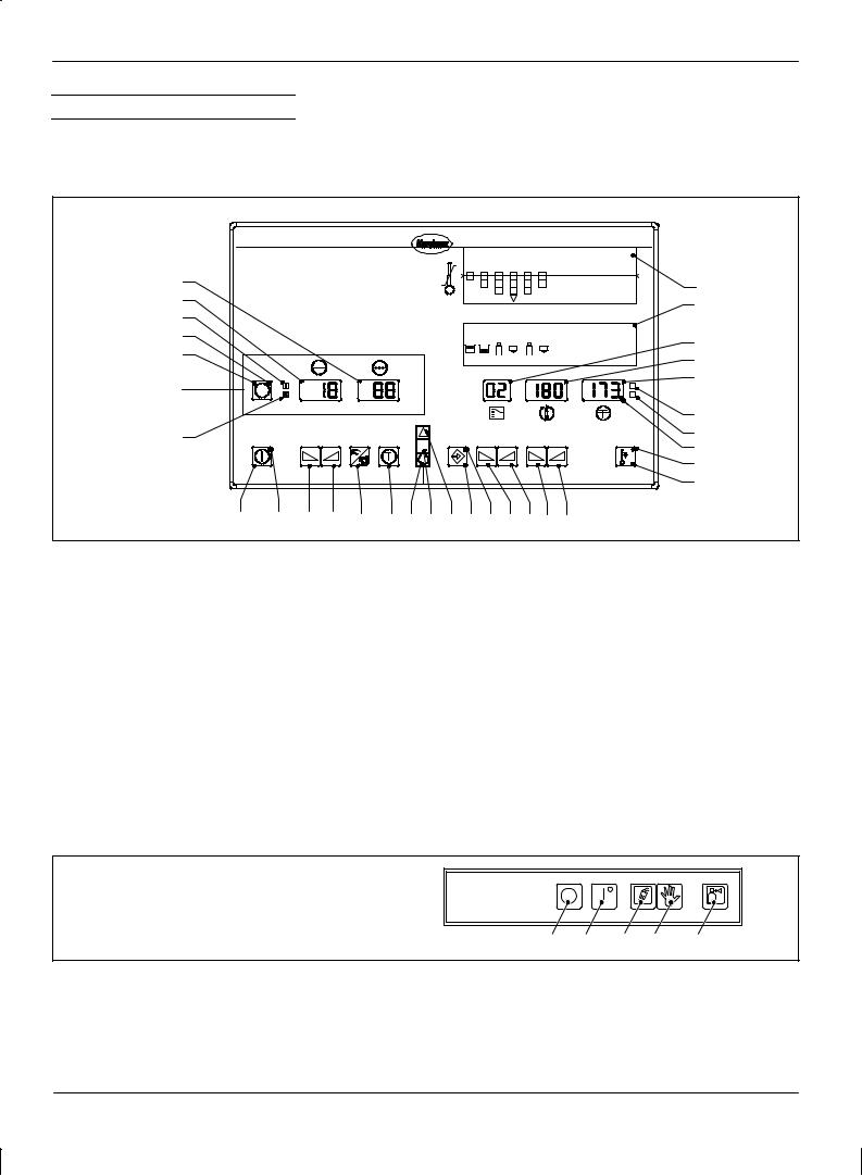
5. Control Panel
The control panel is divided into motor and temperature parts. The elements found in the dotted line box are also referred to as the motor panel in the following description (up to 6 motor panels per control system are possible). The motor/pump speed is indicated with the SI-unit min-1 (equivalent to rpm).
Motor part |
Temperature part |
1 2 3 4 5 6
R
31
30
29
28 |
|
|
1 |
2 |
3 |
4 |
5 |
6 |
|
|
|
|
|
|
|
|
|
27 |
|
|
|
|
1 |
1 |
2 |
2 |
|
|
n |
|
|
|
|
|
|
|
|
min |
|
|
|
|
|
|
Motor panel |
M1 |
min±1 |
bar |
|
|
|
|
C |
|
x10 psi |
|
|
|
|
F |
||
26 |
|
|
|
|
|
|
|
|
1
2
3
4
5
6
7 8
9
10
25 |
24 |
23 |
22 |
21 |
20 19 18 17 16 15 14 1312 11 |
MXCO001L084A0195 |
Fig. 1
1.Bar graph (option)
2.Channel allocation
3.Display Temperature channels
4.Display Temperature setpoint
5.Display Actual temperature
6.Illuminated symbol
! " "$" (°C)
7.Illuminated symbol ! "
F ! # (°F)
8.Decimal point H #
9.LED ! #$! " #
10.Key Temperature setback on/off
11.Key ! " %$"
12. |
Key ! " %$" |
23. |
Key ! " # ! $ " |
|
13. |
Key $ |
24. |
LED # ! " O |
|
14. |
Key & |
25. |
Key # ! " O O |
|
15. |
LED # ! ' |
26. |
Illuminated symbol $ |
|
16. |
Enter key |
27. |
Key Motor pre-selection |
|
17. |
Indication lamp # % $# (red) |
28. |
LED # ! ! (" # |
|
18. |
Indication lamp & # O (white) |
29. |
Illuminated symbol # ! O |
|
19. |
Indication lamp ' (green) |
30. |
Display # !$ |
" |
20. |
Key "# |
31. |
Display ! ""$! O |
# |
21.Key $ $# #
22.Key ! " # ! $ "
Only MC units
Refer to separate unit manual for key description
Fig. 2 Additional control panel MC
1.Key Heating off
2.Key Heating on
1 |
2 |
3 |
4 |
5 |
|
|
|
|
002159 |
3. |
Illuminated symbol Inert gas supply |
5. Illuminated symbol Inert gas bottle |
4. |
Key Purge (inert gas flush) |
empty |
|
P/N 412960D |
CS03 |
|
Issued 07/01 |
E 2001 Nordson Corporation
All rights reserved

Control system CS 20 |
5 |
6.Control Panel for Double Stream Pumps
A pressure sensor can be installed for each pump stream. The control system offers the option of displaying both pump stream pressures. There are two display lines for each motor on the motor control panel (Fig. 3). In the second line of each display, the pressure of the second pump stream and all parameters relevant for this pump stream are shown.
27 |
30 |
31 |
|
29 |
bar |
|
min±1 |
|
|
|
psi |
|
26 |
|
bar psi
25 |
23 |
22 |
21 |
20 |
002353
Fig. 3 Motor control panel for 1 motor
If the system contains a control panel for double stream pumps, the software automatically activates the functions needed for the double stream pumps. If the system uses an analog module to compile pressure, both pressure displays are activated for each motor.
E 2001 Nordson Corporation All rights reserved
CS03 |
P/N 412960D |
Issued 07/01 |
|

6 Control system CS 20
7.Indication Lamps and Indicator Beacon
The indication lamps and the optional indicator beacon show the operating modes: Collective fault, Switched on and Ready for operation.
The switching of the indicator beacon is carried out differently depending on the unit series. For certain series and special versions, the indicator beacon may contain further lamps. The functioning is described in the manual for the unit/system.
|
|
|
|
|
|
|
|
|
|
|
|
|
|
17 Red |
|
|
1 |
2 |
3 |
4 |
5 |
6 |
7 |
8 |
9 |
10 11 |
12 |
18 White |
|
|
|
|
|
|
|
|
|
|
|
|
|
|
|
|
|
|
1 |
2 |
3 |
4 |
5 |
6 |
7 |
8 |
9 |
10 11 |
12 |
|
|
|
|
|
|
1 |
1 |
2 |
2 |
3 |
3 |
4 |
4 |
1 |
2 |
|
M1 |
min±1 |
bar |
|
|
|
|
|
|
|
|
|
|
C |
19 Green |
|
|
psi |
|
|
|
|
|
|
|
|
|
|
F |
|
|
|
|
|
|
|
|
|
|
|
|
|
|
|
MXCO054L067A1295 |
Fig. 4 (Also refer to Fig. 1 for position numbers)
Indication lamp |
Message(s) |
Notes |
|
|
|
Red (17) |
Overtemperature message from control system |
Display 5: Hi blinking |
Collective fault |
Overtemperature shutdown by control system, |
Displays 3, 4 and 5: 2 ±±± ±±± blinking |
|
e.g. channel 2 |
|
|
|
|
|
Undertemperature during operation |
Display 5: Lo blinking |
|
Ambient temperature too high |
Displays 3, 4 and 5: AM bIE nT blinking |
|
Temperature sensor short circuit |
Display 5: - S - blinking |
|
Temperature sensor interruption |
Display 5: ± E ± blinking |
|
|
|
|
Speed alarm (special function) |
Display 30: r_d indicated |
|
Memory error |
Displays 4 and 5: Error blinking |
|
|
|
|
Coupling fault (special function) |
Display 30: CLU indicated |
|
|
|
|
Underpressure alarm (special function) |
Display 30: Plo indicated |
|
|
|
|
Overpressure alarm (special function) |
Display 30: Phi indicated |
|
|
|
|
Safety valve opened (special function) |
Display 30: bPo indicated |
|
|
|
|
Other error messages |
Display 30: Err indicated |
|
(Refer to service display Error) |
Display 31: Error number indicated |
|
|
|
White (18) |
After switching on the unit and during the initial heating |
If, after the initial heating phase (1 hour and longer), the |
Switched on |
phase, only the white indication lamp is lit |
green indication lamp is not lit: Refer to manual Unit/system, |
|
section Troubleshooting |
|
|
|
|
|
|
|
Green (19) |
The green indication lamp does not light until all channels |
|
Ready for opera- |
have reached their temperature setpoints and when the fol- |
|
lowing conditions have been met: |
|
|
tion |
|
|
|
|
|
|
Release Unit must be bridged or activated |
Refer to manual Unit/system, section Installation, XS 2 |
|
|
Interface |
|
|
|
|
Temperature setback may not be switched on |
Refer to section Temperature Setback in this manual and to |
|
|
section Installation, Interface XS 2 in the manual Unit/system. |
|
|
|
P/N 412960D |
CS03 |
|
Issued 07/01 |
E 2001 Nordson Corporation
All rights reserved

Control system CS 20 |
7 |
8. Overview of Settings
Temperature Part
The possible settings and parameters described here are not available for every unit/system (Refer to column Notes).
The indexes in the column Notes indicate the corresponding position in the separate communication data list. These references can be ignored when a control system CS 20 without PROFIBUS is used.
± ± ± means that the function is switched off. Do this by setting the value to > 9.99.
Parameter |
Function / possible setting |
Setting range |
Factory |
Notes |
|
|
|
|
|
setting |
|
|
|
|
|
|
|
|
|
Temperature setpoint for each channel |
Refer to manual for |
Depends on |
Index 154 |
|
|
|
unit/system, section |
unit |
|
|
|
|
Specifications |
|
|
|
|
|
|
|
|
|
SPL |
Temperature setback (setback value) |
5 to 100 °C (9 to 180 °F) |
50 °C |
Index 166 |
h |
SPL |
Temperature setback (setback period) |
0.05 to 9.99 hours |
± ± ± (off) |
± |
|
|
|
|
|
|
CO |
OFF |
Inert gas control (interval) |
2 to 120 minutes |
30 minutes |
Index 36 |
|
|
|
|
|
Option |
|
|
|
|
|
|
CO |
On |
Inert gas control (injection period) |
2 to 120 seconds |
5 seconds |
Index 35 |
|
|
|
|
|
Option |
|
|
|
|
|
|
|
t1 |
Control mode |
1 to 180 minutes |
30 min |
Only for MC 4420, |
|
|
|
|
|
channel 11 and 12 |
|
|
|
|
|
|
|
Lo |
Undertemperature value |
5 to 30 °C (9 to 54 °F) |
10 °C |
Index 163 |
|
Hi |
Overtemperature value |
5 to 30 °C (9 to 54 °F) |
10 °C |
Index 164 |
|
OFF |
Overtemperature shutdown |
70 to 260 °C (158 to 500 °F); |
± |
Only display |
|
|
|
70 to 280 °C (158 to 536 °F) |
|
|
|
|
|
with high temperature units |
|
|
|
|
|
|
|
|
|
Pid |
Predefined control parameters |
SLO, nor, FA1, FA2 |
nor |
SLO: Slow controlled |
|
|
|
|
|
system |
|
|
|
|
|
nor: Normal controlled |
|
|
|
|
|
system |
|
|
|
|
|
FA1: Fast controlled system |
|
|
|
|
|
FA2: Fast controlled system |
|
|
|
|
|
|
|
SE |
Service display (sensor type) |
Pt, FEC, ni |
± |
Only display |
|
|
|
|
|
|
|
°C |
Select temperature display in °C or °F |
°C / °F |
°C |
± |
|
CLr |
Return parameter to factory setting |
no / yes |
no |
± |
|
|
|
|
|
|
E 2001 Nordson Corporation All rights reserved
CS03 |
P/N 412960D |
Issued 07/01 |
|

8 |
Control system CS 20 |
|
|
|
|
||
Motor Part |
OFF means that the function is switched off. Do this by setting value to 0 |
|
|||||
|
|
(zero). |
|
|
|
|
|
|
|
|
|
|
|
|
|
Parameter |
Function / possible setting |
|
Setting range |
Factory setting |
Notes |
|
|
|
|
|
|
|
|
|
|
rSP |
|
Speed setpoint for each motor panel |
|
1.0 to 100 min-1 |
5.0 min-1 |
Index 75 |
|
|
|
(manual mode) |
|
|
|
|
|
|
|
|
|
|
|
|
|
rLo |
|
Speed at 0% pilot voltage |
|
1.0 to 100 min-1 |
1.0 min-1 |
Index 80 |
|
|
|
|
|
|
|
Special function may be |
|
|
|
|
|
|
|
activated |
|
|
|
|
|
|
|
|
|
rhi |
|
Speed at pilot voltage Uhi |
|
1.0 to 100 min-1 |
80 min-1 |
Index 79 |
|
Uhi |
|
Pilot voltage in % at which the motor |
|
0 to 100 % pilot voltage |
100 % |
Index 78 |
|
|
|
rotates at speed rhi. If the pilot voltage |
|
|
|
Special function may be |
|
|
|
exceeds Uhi, the speed remains constant |
|
|
|
|
|
|
|
|
|
|
activated |
|
|
|
|
at rhi. |
|
|
|
|
|
|
|
|
|
|
|
|
|
|
|
|
|
|
|
|
|
PSL |
|
Pressure at 0% pilot voltage |
|
0.1 bar to 70 % of pressure |
1 % of pressure |
Special function |
|
|
|
|
|
measuring range upper limit |
measuring range |
|
|
|
|
|
|
|
upper limit |
|
|
|
|
|
|
|
|
|
|
PSH |
|
Pressure at pilot voltage Uhi |
|
0.1 bar to 70 % of pressure |
10 % of pressure |
Special function |
|
|
|
|
|
measuring range upper limit |
measuring range |
|
|
|
|
|
|
|
upper limit |
|
|
|
|
|
|
|
|
|
|
PSP |
|
Pressure setpoint for each motor panel |
|
OFF or 0.1 to 70 % of |
OFF |
Special function |
|
|
|
(manual mode) |
|
pressure measuring range |
|
|
|
|
|
|
|
upper limit |
|
|
|
|
|
|
|
|
|
|
|
PAH |
|
Overpressure value |
|
OFF or 2.0 to 30 % of |
OFF |
Special function |
|
|
|
|
|
pressure measuring range |
|
|
|
|
|
|
|
upper limit |
|
|
|
|
|
|
|
|
|
|
|
PAL |
|
Underpressure value |
|
OFF or 2.0 to 30 % of |
OFF |
Special function |
|
|
|
|
|
pressure measuring range |
|
|
|
|
|
|
|
upper limit |
|
|
|
|
|
|
|
|
|
|
|
SPL |
|
Period after motor standstill at which the |
|
15 to 240 minutes |
OFF |
± |
|
|
|
temperature setback is automatically |
|
|
|
|
|
|
|
switched on |
|
|
|
|
|
|
|
|
|
|
|
|
|
PSI |
|
Select pressure display in bar or psi |
|
no (bar) / yes (psi) |
(no) bar |
Option |
|
|
|
|
|
|
|
|
|
PdS |
|
Switch on/off second line of display when |
|
ON: Second line switched |
ON |
The parameter is shown |
|
|
|
both single and double stream pumps are |
|
on |
|
only in the second line. |
|
|
|
used. |
|
OFF: Second line switched |
|
|
|
|
|
|
|
|
|
|
|
|
|
|
|
off |
|
|
|
|
|
|
|
|
|
|
|
PrS |
|
Variable pressure measuring range |
|
1 to 680 bar |
100 bar |
Special function |
|
|
|
|
|
|
|
|
|
Plo |
|
Pressure monitoring for underpressure |
|
OFF or 1 to x bar |
OFF |
Index 126 |
|
|
|
|
|
(x = pressure sensor |
|
Special function |
|
|
|
|
|
measuring range) |
|
|
|
|
|
|
|
|
|
|
|
|
|
|
|
|
|
|
|
Phi |
|
Pressure monitoring for overpressure |
|
OFF or 1 to x bar |
OFF |
Index 125 |
|
|
|
|
|
(x = pressure sensor |
|
Special function |
|
|
|
|
|
measuring range) |
|
|
|
|
|
|
|
|
|
|
|
|
|
|
|
|
|
|
|
P/N 412960D |
CS03 |
|
Issued 07/01 |
E 2001 Nordson Corporation
All rights reserved

Control system CS 20 |
9 |
Parameter |
Function / possible setting |
Setting range |
Factory |
Notes |
|
|
|
|
setting |
|
|
|
|
|
|
|
|
SLo |
Threshold value switch |
OFF or 1.0 to 100 % pilot |
OFF |
Index 94 |
|
|
(Pilot voltage in % at which the motor stops) |
voltage |
|
Option |
|
|
|
|
|||
|
|
|
|
|
|
Shi |
Threshold value switch |
OFF or 1.0 to 100 % pilot |
OFF |
Index 95 |
|
|
(Pilot voltage in % at which the motor starts) |
voltage |
|
Option |
|
|
|
|
|||
|
|
|
|
|
|
drS |
Reverse mode |
OFF or 1.0 to 100 min-1 |
OFF |
Index 86 |
|
|
(Speed at which the motor rotates in |
|
|
Option |
|
|
reverse after switching off) |
|
|
|
|
|
|
|
|
|
|
drt |
Reverse mode |
0.5 to 25 seconds |
0.5 seconds |
Index 87 |
|
|
(Period in which the motor rotates in reverse |
|
|
Option |
|
|
after switching off) |
|
|
|
|
|
|
|
|
|
|
rPU |
Adapting speed to special gearbox |
1.0 to 250 min-1 |
100 min-1 |
Index 83 |
|
|
|
|
|
Special function may be |
|
|
|
|
|
activated |
|
|
|
|
|
|
|
r_d |
Speed alarm |
OFF or 2 to 10 min-1 |
OFF |
Index 81 |
|
|
|
|
|
Only on units with actual speed |
|
|
|
|
|
compiling |
|
|
|
|
|
|
|
Con |
Inert gas control (injection period) |
OFF or 2 to 120 seconds |
5 seconds |
Con: Index 35 |
|
|
|
|
|
CoF: Index 36 |
|
CoF |
Inert gas control (interval) |
2 to 120 minutes |
30 minutes |
||
The parameters Con, CoF, C1 |
|||||
|
|
|
|
||
|
|
|
|
and C2 are only in the system if |
|
C1 |
Forcibly actuated inert gas injection |
2 to 240 seconds |
30 seconds |
||
|
|
|
|
the selector switch S 11 of the |
|
|
|
|
|
central module is set to B. They |
|
C2 |
Forcibly actuated air exhaust (vacuum |
OFF or 2 to 240 seconds |
60 seconds |
||
are used only for certain units in |
|||||
|
pump) |
|
|
||
|
|
|
the series MC ... . |
||
|
|
|
|
||
CLr |
Return values to factory setting |
no / yes |
no |
± |
|
|
|
|
|
|
|
Adr |
Field bus address of unit |
2 to 126 |
10 |
Index 9 |
|
|
|
|
|
Only with option PROFIBUS DP |
|
|
|
|
|
|
E 2001 Nordson Corporation All rights reserved
CS03 |
P/N 412960D |
Issued 07/01 |
|

10 Control system CS 20
Operating the Temperature Part
WARNING: Allow only qualified personnel to perform the following tasks. Observe and follow the safety instructions in this document and all other related documentation.
Operation by electrostatically-charged persons can lead to improper functioning of the control system.
P/N 412960D |
CS03 |
|
Issued 07/01 |
E 2001 Nordson Corporation
All rights reserved
Control system CS 20 |
11 |
1. Operation Overview
Displays |
C / F status display |
Refer to Overview of Displays and Diagnosis
Program in technical appendix.
|
|
3 |
|
4 |
5 |
|
|
|
|
|
C |
|
|
|
|
|
F |
|
|
|
|
|
Decimal point |
|
|
|
|
|
Lit when the displayed |
|
|
|
|
|
channel is heating. |
16 |
14 |
13 |
12 |
11 |
10 |
|
|
|
|
|
MXCO004L050A0295 |
Switching channels / selecting parameters
Press key 13 or 14 until the desired channel appears in display 3.
When the highest channel that is switched on is exceeded, the following displays/parameters can be called up:
SPL Temperature setback value
h SPL Temperature setback period
Co |
OFF Inert gas interval (option) |
Co |
On Inert gas injection period (option) |
Lo |
Undertemperature value |
Hi |
Overtemperature value |
OFF Overtemperature switchoff
SE Service display (sensor type)
°C / °F Temperature unit
CLr Return parameter to factory setting
If no other key is pressed with 120 sec., these displays return to the leading channel or the channel with the lowest number.
Switching on/off immediate temperature setback
Switching ON: Press key 10; SPL blinks in display 4 and the LED in the key lights.
Switching OFF: Press key 10 or wait until the setback period has expired (if the setback period is longer than 9.99 hours, the temperature setback is not automatically ended).
Note: The temperature setback can also be switched on via the XS 2 interface. When the temperature setback is switched on, SPL blinks in displays 4 and 30 (Fig. 1). A setback period is ineffective in this case.
Note: The Automatic Temperature Setback After Motor Standstill is ended by pressing key 25 (Fig. 1) on the motor part. Press key 25 for approx. 2 seconds.
Setting temperature setpoint and parameters
Hold down key 16 and increase value with key 11 or decrease with key 12 .
Pressing once changes the value by 1, holding the key changes the value faster.
The LED in key 16 is lit when adjustable parameters are shown in displays 3, 4 and 5. The following parameters can be adjusted:
Temperature setpoint
SPL Temperature setback value
h SPL Temperature setback period
Co |
OFF Inert gas interval (option) |
|
Co |
On |
Inert gas injection period (option) |
Lo |
|
Undertemperature value |
Hi |
|
Overtemperature value |
°C / °F |
Temperature unit |
|
CLr |
|
Return parameter to factory setting |
t1 |
|
(only MC 4420) |
Fig. 5
E 2001 Nordson Corporation All rights reserved
CS03 |
P/N 412960D |
Issued 07/01 |
|

12 Control system CS 20
2. Display Overview
Some parameters can be set individually for each channel. Refer to
Setting Parameters by Channel.
Values can be adjusted in these displays (through parameter Hi)
Lo / untertemperature (during initial heating phase) Initial display when unit is switched on.
Channel |
Temperature setpoint Undertemperature |
Normal display
Appears when the channel is heated up.
Channel |
Temperature setpoint Actual temperature |
SPL / temperature setback
Setback value
Setback period
9.99 hours exceeded
CO / inert gas control (option)
For MX units
Interval
Injection period
Control mode
Only for MC 4420, channel 11 and 12
Time
Lo / undertemperature value
Hi / overtemperature value
B
B
B
When the highest active channel is exceeded, these displays can be called up in this order.
B
OFF / overtemperature shutdown
The overtemperature shutdown value is set automatically 30 °C (54 °F) higher than the highest temperature setpoint value.
SE / service display (sensor type)
The type of temperature sensor used can be determined via the service display.
Fe-CuNi
Temperature unit (°C / °F)
Return parameter to factory setting
Operating mode displays
Appear automatically.
Temperature setback on
Also refer to Switching immediate temperature setback on/off.
Unit release not switched
Heaters and motors are switched off
Startup control with leading channel is active.
B
Fig. 6
P/N 412960D |
CS03 |
|
Issued 07/01 |
E 2001 Nordson Corporation
All rights reserved

|
Control system CS 20 |
13 |
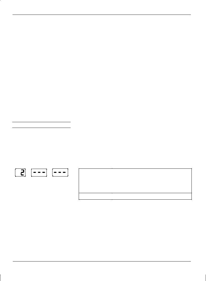
Automatic Fault Displays |
|
|
Overtemperature shutdown |
Undertemperature during operation |
|
Ambient temperature too high |
Overtemperature |
|
Temperature sensor interruption |
Memory error |
|
|
Diagnosis displays |
|
|
Not shown here. Refer to Technical Appendix for |
|
Temperature sensor short circuit |
Temperature Part, Diagnosis Program. |
|
|
|
Fig. 7
Overview of Parameters Set by Channel
Also refer to Setting Parameters, Setting Parameters by Channel and DIP switch S 8 on the temperature control panel board.
Normal display
Display by channel
PID parameter set
Regulation ratio (only display)
Service display (sensor type)
Fig. 8
E 2001 Nordson Corporation All rights reserved
CS03 |
P/N 412960D |
Issued 07/01 |
|

14 Control system CS 20
3. Basic Settings
Startup Control with Leading Channel
The startup control with leading channel is only active if a leading channel has been selected. It prevents hot melt material from charring in hoses/application heads and the build-up of material expansion pressure during the initial heating phase. It also helps to save energy.
WARNING: If no leading channel has been selected, the tank temperature can be set to an unpermissible high value. This can damage O-rings and the allowable temperature of the unit surfaces may be exceeded. This warning does not apply to high temperature units!
Factory setting: The factory setting depends on the system model. The channel with the longest initial heating phase should be chosen as leading channel.
Setting range: See Technical Appendix of the Temperature Part, Temperature Control Panel Board, DIP Switch S 8
e e e i e ec i e i e ei
|
|
3 |
|
4 |
5 |
|
|
|
|
|
C |
|
|
|
|
|
F |
|
|
|
|
|
8 |
|
15 |
|
|
|
9 |
16 |
14 |
13 |
12 |
11 |
10 |
MXCO010S025A0295
Fig. 9 Details from Fig. 1
Depending on the display selected, either C (Celsius) or F (Fahrenheit) of status display 8 is lit. When display is in Fahrenheit, the control system continues to use Celsius internally. This may result in up to one degree Fahrenheit being skipped.
Changing: Use key 13 to select display temperature unit. Press key 16 until ±P± blinks in display 5. Change to the other temperature unit using key 11 or key 12. Status display 8 changes accordingly.
Factory setting: Degrees Celsius (°C)
Switching Scan Mode On/Off |
In Scan Mode, all activated channels are displayed consecutively at |
|
|
3 second intervals. |
|
|
Switching ON: Press keys 13 and 14 simultaneously. |
|
|
Switching OFF: Press key 13 or 14. |
|
|
|
|
|
Factory setting: |
Scan Mode switched off |
P/N 412960D |
CS03 |
|
Issued 07/01 |
E 2001 Nordson Corporation
All rights reserved

Control system CS 20 |
15 |
Selecting Control or Measuring Mode
Control mode is the normal function of a channel. The actual temperature is adapted to the setpoint temperature and kept stable.
In measuring mode, temperature control and monitoring for faults do not take place. Display 4 is switched off. The measured temperature appears in display 5. The leading channel cannot be switched into measuring mode.
|
|
3 |
|
4 |
5 |
|
|
|
|
|
C |
|
|
|
|
|
F |
|
|
|
|
|
8 |
|
15 |
|
|
|
9 |
16 |
14 |
13 |
12 |
11 |
10 |
MXCO010S025A0295
Factory setting: Control mode
Selecting measuring mode: Set temperature setpoint of the channel to be measured to 40 C (104 F). Press and hold key 16 and press key 12 twice.
Switching back to control mode: Press and hold key 16 and press key
11 twice.
Fig. 10 Details from Fig. 1
Switching Channel On/Off
Unused channels are switched off. Switched-off channels are no longer displayed. The leading channel can not be switched off. Switching on unconnected channels causes error message 34.
Switching off: Set temperature setpoint to 40 °C (104 °F). Press and hold key 16 and press key 12 once.
Switching ON:
1.Use key 13 or 14 to select the last switched-on channel.
2.Press and hold key 16 and use key 13 or 14 to select the switched-off channel.
3.Press and hold key 16 and use key 11 to set the temperature setpoint to 40 C (104 F) or higher.
Display examples
Channel Temperature setpoint Actual temperature |
Status |
|
Channel switched on and |
|
Channel in control mode and |
|
Channel activated |
|
Channel switched on and |
|
Channel in measuring mode and |
|
Channel activated |
|
Channel switched on and |
|
Channel not activated |
|
or Unit release not switched |
|
Channel switched off and |
|
Channel not activated |
|
This means that the channels that are |
|
switched off are not displayed in the menu |
E 2001 Nordson Corporation All rights reserved
CS03 |
P/N 412960D |
Issued 07/01 |
|

16 Control system CS 20
4.Switching Immediate Temperature Setback On/Off
5. Setting Temperature
|
|
3 |
|
4 |
5 |
|
|
|
|
|
C |
|
|
|
|
|
F |
|
|
|
|
|
8 |
|
15 |
|
|
|
9 |
16 |
14 |
13 |
12 |
11 |
10 |
MXCO010S025A0295
Fig. 11 Details from Fig. 1
The temperature setback serves to protect the hot melt material and to save energy during breaks in production. The setback temperature and setback period can be set (refer to Parameter Overview, Parameters SPL and h SPL).
The temperature setback is switched on and off by the operator. (Refer to
Switching On/Off Automatic Temperature Setback in the motor part)
Switching ON: Press key 10; SPL blinks in display 4 and the LED in the key lights.
Switching OFF: Press key 10 or wait until the setback period has expired (if the setback period is longer than 9.99 hours, the temperature setback is not automatically ended).
The temperature setback can also be switched on via the XS 2 interface. When the temperature setback is switched on, SPL blinks in displays 4 and 30 (Fig. 1). A setback period is ineffective in this case.
WARNING: When setting the temperature, the temperature prescribed by the material manufacturer is decisive. The maximum operating temperatures of the unit and of heated system components may not be exceeded.
Nordson will not assume any guarantee or liability for damage caused by incorrect temperature settings.
1.Selecting channel: Press key 13 or 14.
2.Press and hold key 16 (in display 4, ±P± blinks) and use key 11 to increase value or key 12 to decrease value.
Pressing once changes the value by 1, holding the key changes the value faster.
Factory setting: |
Depends on unit |
|
|
Setting range: |
Refer to manual unit/system, section |
|
Specifications |
P/N 412960D |
CS03 |
|
Issued 07/01 |
E 2001 Nordson Corporation
All rights reserved

Control system CS 20 |
17 |
6. Setting Parameters
Setback value
Setting Parameters by Channel
Return Parameter to Factory Setting
1.Press key 13 or 14 until the desired parameters appear in displays 3 and/or 4.
2.Press and hold key 16 (in display 5, ±P± blinks) and use key 11 to increase value or key 12 to decrease value.
Pressing once changes the value by 1, holding the key changes the value faster.
With the parameters SPL, Hi and Lo, all of which can be set individually for each channel, three lines appear in the display when at least one channel has a setting that differs from the others. A setting that applies to all channels is usually sufficient.
Refer to DIP switch S 8 on the temperature control panel board.
Example of Selecting Parameter Set
1.Press and hold keys 11 und 12, then press key16 until the display blinks.
2.Press key 13 or 14 until the desired channel is displayed. Channels that are switched off are automatically skipped.
3.Press key 11 or 12 until Pid is displayed.
4.Select parameter set (Refer to previous section, Setting Parameters)
5.Press and hold keys 11 and 12, then press key 16 at the same time to leave the menu.
If no keys are pressed for approx. 2 minutes, the program automatically returns to the normal display.
1.Press key 13 or 14 until parameter CLr appears in display 4.
2.Press and hold key 16 (in display 5, ±P± blinks) and set displayed value from no to yes, using key 11 or 12.
3.Release all keys. The temperature parameters (with the exception of temperature setpoint values) will be reset to factory settings.
The value will be no again after resetting.
E 2001 Nordson Corporation All rights reserved
CS03 |
P/N 412960D |
Issued 07/01 |
|

18 Control system CS 20
Parameter Overview |
SPL = Setback Temperature |
|
h SPL = Setback Period |
The temperature setback serves to protect the hot melt material and to save energy during breaks in production. After the setback period has expired, the heating is automatically switched back on, but not automatically if the setback period has been set to higher than 9.99 hours. After 9.99 hours, three dashes appear in display 5 (Fig. 1).
SPL |
|
Factory setting: |
50 °C |
|
|
|
|
|
|
Setting range: |
5 °C to 100 °C (9 °F to 180 °C) |
|
|
|
|
h |
SPL |
Factory setting: |
± ± ± (off) |
|
|
|
|
|
|
Setting range: |
0.05 to 9.99 hours |
|
|
|
|
Note: The temperature setback period affects all channels. The setback temperature can also be entered by channel (Also refer to
Display Overview, Setting Parameters by Channel).
The temperature can not be lowered below the lowest temperature setpoint. The setting range for the parameter SPL in then automatically limited.
Co OFF = Inert Gas Interval
Co On = Inert Gas Injection Period
The inert gas control serves to switch on/off the solenoid valve of the optional inert gas equipment. Injection period and interval (time between two injections) can be set.
CO |
OFF |
Factory setting: |
30 minutes |
|
|
|
|
|
|
Setting range: |
2 to 120 minutes |
|
|
|
|
CO |
On |
Factory setting: |
5 seconds |
|
|
|
|
|
|
Setting range: |
2 to 120 seconds |
|
|
|
|
Note: Special function may be activated (only together with optional inert gas equipment). Refer to Technical Appendix of the Tempera- ture Part, Temperature Control Panel Board, DIP-Switch S 8.
This additional function must be deactivated for units in the series
MC ... The inert gas equipment described in the motor part is used with these units (parameters CoF and Con )
t1 = Control Mode
Time in which the temperature channels 11 and 12 are in control mode. When this time has expired, the channels are automatically deactivated.
t1 |
Factory setting: |
30 minutes |
Note: Only for MC 4420, channel 11 and 12. |
|
|
|
|
|
Setting range: |
1 to 180 minutes |
|
|
|
|
|
P/N 412960D |
CS03 |
|
Issued 07/01 |
E 2001 Nordson Corporation
All rights reserved

Control system CS 20 |
19 |
Lo = Undertemperature Value/Interlock
The undertemperature locking device prevents the unit or system from being started up when the application material is too cold until the temperature setpoint minus undertemperature value has been exceeded. On every initial heating, however, the locking device is not released until the actual temperature is 3 °C (5.4 °F) below the temperature setpoint .
The undertemperature locking device blocks the motors, and possibly other components of the application system. Refer to the Wiring Diagram for an indication of which components are blocked.
Lo |
Factory setting: |
10 °C |
Note: The undertemperature value can also be entered by channel |
|
|
|
(Also refer to Display Overview, Setting Parameters by Channel). |
|
Setting range: |
5 °C to 30 °C (9 °F to 54 °C) |
Note for MC 4420:The alarm is deactivated for channels 11 and 12. |
|
|
|
|
|
|
|
|
Hi = Overtemperature Value
When the temperature setpoint plus overtemperature value has been reached, the relay output Collective fault is switched and the red indication lamp Collective fault lights. The unit remains ready for operation.
Hi |
Factory setting: |
10 °C |
Note: The overtemperature value can also be entered by channel |
|
|
|
(Also refer to Display Overview, Setting Parameters by Channel). |
|
Setting range: |
5 °C to 30 °C (9 °F to 54 °C) |
Note for MC 4420: The alarm is deactivated for channels 11 and 12. |
|
|
|
|
|
|
|
|
OFF = Overtemperature Shutdown
When the overtemperature shutdown reacts (refer to Automatic fault displays), there is a unit fault. Switch off the unit and have the fault eliminated by qualified personnel.
Pid = Predefined Control Parameters
WARNING: The PID controller may be adjusted only by personnel trained especially in control technology.
The control parameters (parameter sets SLO, nor, FA1, FA2) can only be set by channel. Refer to DIP switch S 8 on the temperature control panel board.
Pid |
Factory setting: |
nor |
SLO: Slow controlled system |
|
|
|
nor: Normal controlled system |
|
|
|
FA1: Fast controlled system |
|
Setting range: |
SLO, nor, FA1, FA2 |
|
|
|
|
FA2: Fast controlled system |
|
|
|
|
E 2001 Nordson Corporation All rights reserved
CS03 |
P/N 412960D |
Issued 07/01 |
|
20 |
Control system CS 20 |
|
|
|
|
On = Regulation Ratio (Display) |
|
|
|
The regulation ratio determines the percentage of an interval during |
|
|
|
which the heater output is switched on. |
|
|
|
Range of values: 0 to 100 % |
|
|
|
100 % means that the heater output is always on. |
|
|
|
SE = Service Display |
|
|
|
The user can find out the type of temperature sensor used for |
|
|
|
temperature module 1 via the service display SE; for each channel under |
|
|
|
Setting by Channel: |
|
|
|
S FEC = Fe-CuNi |
|
|
|
S Pt = Pt 100 |
|
|
|
S ni = Ni 120. |
|
7. |
Automatic Fault Displays |
If multiple faults are present, the channel with the lowest channel number |
|
|
|
and the fault with the highest priority are displayed. |
|
|
|
The number of a faulty channel appears in the left display; the fault |
|
|
|
indication is shown in the middle and right displays. |
|
|
|
Overtemperature shutdown |
|
|
|
The shutdown depends on the setting of the DIP switch S 8.8 on the |
|
|
|
temperature control panel board (Refer to Technical Appendix for |
|
|
|
Temperature Part). |
|
|
|
Activation |
When the overtemperature shutdown value is |
|
|
|
reached |
|
|
|
or |
|
|
|
Shutdown temperature was exceeded for more |
|
|
|
than 120 seconds / temperature increased |
|
|
Deactivation |
Switch on/off unit |
P/N 412960D |
CS03 |
|
Issued 07/01 |
E 2001 Nordson Corporation
All rights reserved
 Loading...