

NordicTrack VXR 475 NTEVEX84916.0 User Manual
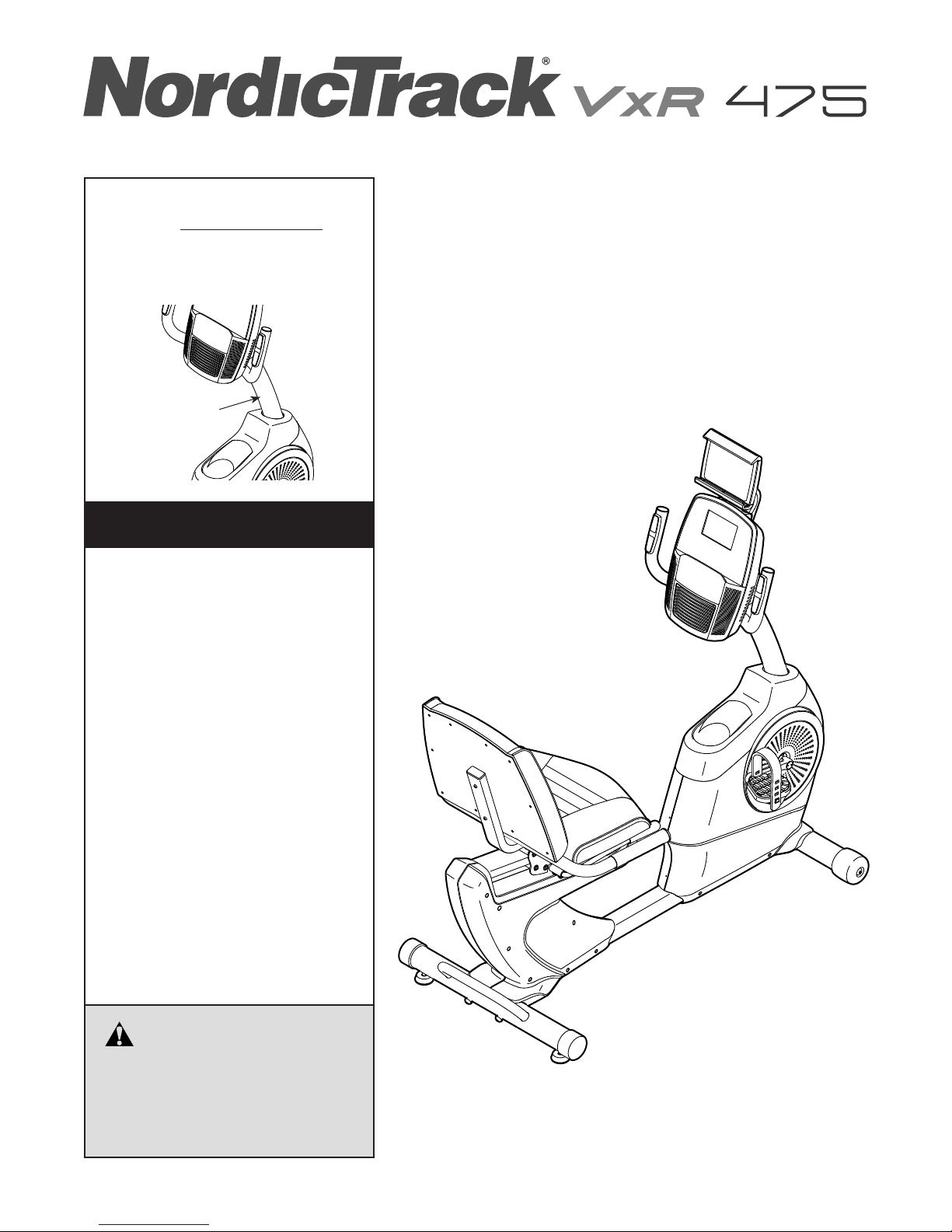
Model No. NTEVEX84916.0
Serial No.
Write the serial number in the space
above for reference.
Serial
Number
Decal
CUSTOMER SERVICE
UNITED KINGDOM
Call: 0330 123 1045
From Ireland: 053 92 36102
Website: www.iconsupport.eu
E-mail: csuk@iconeurope.com
Write:
ICON Health & Fitness, Ltd.
Unit 1D, The Gateway
Fryers Way, Silkwood Park
OSSETT
WF5 9TJ
UNITED KINGDOM
USER’S MANUAL
AUSTRALIA
Call: 1800 993 770
E-mail: australiacc@iconfitness.com
Write:
ICON Health & Fitness
PO Box 635
WINSTON HILLS NSW 2153
AUSTRALIA
CAUTION
Read all precautions and
instructions in this manual before
using this equipment. Keep this
manual for future reference.
www.iconeurope.com
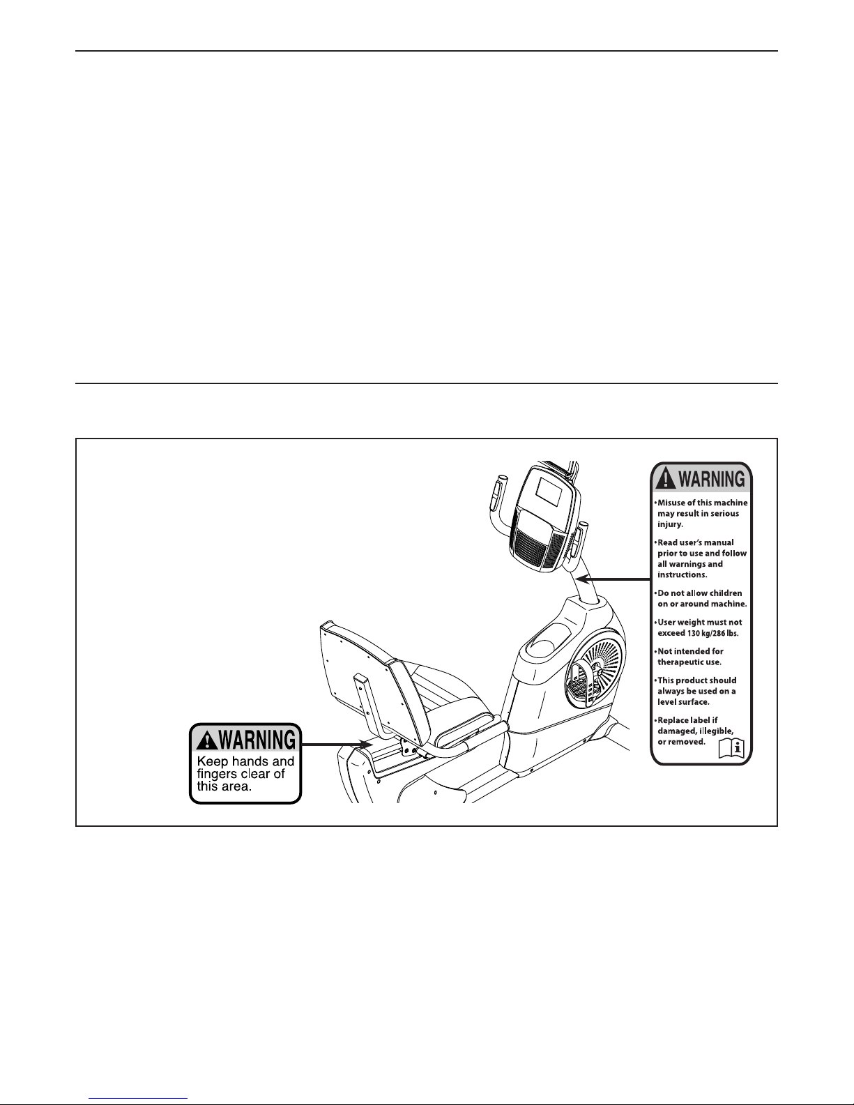
TABLE OF CONTENTS
WARNING DECAL PLACEMENT . . . . . . . . . . . . . . . . . . . . . . . . . . . . . . . . . . . . . . . . . . . . . . . . . . . . . . . . . . . . . . .2
IMPORTANT PRECAUTIONS ..................................................................3
BEFORE YOU BEGIN. . . . . . . . . . . . . . . . . . . . . . . . . . . . . . . . . . . . . . . . . . . . . . . . . . . . . . . . . . . . . . . . . . . . . . . .4
PART IDENTIFICATION CHART. . . . . . . . . . . . . . . . . . . . . . . . . . . . . . . . . . . . . . . . . . . . . . . . . . . . . . . . . . . . . . . .5
ASSEMBLY . . . . . . . . . . . . . . . . . . . . . . . . . . . . . . . . . . . . . . . . . . . . . . . . . . . . . . . . . . . . . . . . . . . . . . . . . . . . . . . .6
HOW TO USE THE EXERCISE BIKE. . . . . . . . . . . . . . . . . . . . . . . . . . . . . . . . . . . . . . . . . . . . . . . . . . . . . . . . . . . 13
MAINTENANCE AND TROUBLESHOOTING ....................................................22
EXERCISE GUIDELINES ....................................................................23
PART LIST. . . . . . . . . . . . . . . . . . . . . . . . . . . . . . . . . . . . . . . . . . . . . . . . . . . . . . . . . . . . . . . . . . . . . . . . . . . . . . . .25
EXPLODED DRAWING. . . . . . . . . . . . . . . . . . . . . . . . . . . . . . . . . . . . . . . . . . . . . . . . . . . . . . . . . . . . . . . . . . . . . .26
ORDERING REPLACEMENT PARTS .................................................. Back Cover
RECYCLING INFORMATION ......................................................... Back Cover
WARNING DECAL PLACEMENT
This drawing shows the location(s) of the warning
decal(s). If a decal is missing or illegible, see
the front cover of this manual and request a
free replacement decal. Apply the decal in the
location shown. Note: The decal(s) may not be
shown at actual size.
NORDICTRACK is a registered trademark of ICON Health & Fitness, Inc. IFIT is a registered trademark of ICON
Health & Fitness, Inc. App Store is a trademark of Apple Inc., registered in the U.S. and other countries. Android
and Google Play are trademarks of Google Inc. The BLUETOOTH® word mark and logos are registered trademarks of Bluetooth SIG, Inc. and are used under license. IOS is a trademark or registered trademark of Cisco in
the U.S. and other countries and is used under license.
2

IMPORTANT PRECAUTIONS
WARNING: To reduce the risk of serious injury, read all important precautions and
instructions in this manual and all warnings on your exercise bike before using your exercise bike.
ICON assumes no responsibility for personal injury or property damage sustained by or through the
use of this product.
1. It is the responsibility of the owner to ensure
that all users of the exercise bike are adequately informed of all precautions.
2. Before beginning any exercise program,
consult your physician. This is especially
important for persons over age 35 or persons with pre-existing health problems.
3. The exercise bike is not intended for use by
persons with reduced physical, sensory, or
mental capabilities or lack of experience and
knowledge, unless they are given supervision or instruction about use of the exercise
bike by someone responsible for their safety.
4. Use the exercise bike only as described in
this manual.
5. The exercise bike is intended for home use
only. Do not use the exercise bike in a commercial, rental, or institutional setting.
6. Keep the exercise bike indoors, away from
moisture and dust. Do not put the exercise
bike in a garage or covered patio, or near
water.
7. Place the exercise bike on a level surface
with at least 2 ft. (0.6 m) of clearance around
the exercise bike. To protect the floor or
carpet from damage, place a mat under the
exercise bike.
8. Inspect and properly tighten all parts each
time the exercise bike is used. Replace any
worn parts immediately.
9. Keep children under age 13 and pets away
from the exercise bike at all times.
10. Wear appropriate clothes while exercising;
do not wear loose clothes that could become
caught on the exercise bike. Always wear
athletic shoes for foot protection.
11. The exercise bike should not be used
by persons weighing more than 286 lbs.
(130 kg).
12. Be careful when mounting and dismounting
the exercise bike.
13. The heart rate monitor is not a medical
device. Various factors, including the user’s
movement, may affect the accuracy of heart
rate readings. The heart rate monitor is
intended only as an exercise aid in determining heart rate trends in general.
14. Always keep your back straight while using
the exercise bike; do not arch your back.
15. Over exercising may result in serious injury
or death. If you feel faint, if you become short
of breath, or if you experience pain while
exercising, stop immediately and cool down.
3
BEFORE YOU BEGIN
Thank you for selecting the new NORDICTRACK®
VXR 475 exercise bike. Cycling is an effective exercise
for increasing cardiovascular fitness, building endurance, and toning the body. The VXR 475 exercise bike
provides a selection of features designed to make your
workouts at home more effective and enjoyable.
For your benefit, read this manual carefully before
you use the exercise bike. If you have questions after
Length: 4 ft. 9 in. (145 cm)
Width: 2 ft. 1 in. (64 cm)
Weight: 101 lbs. (46 kg)
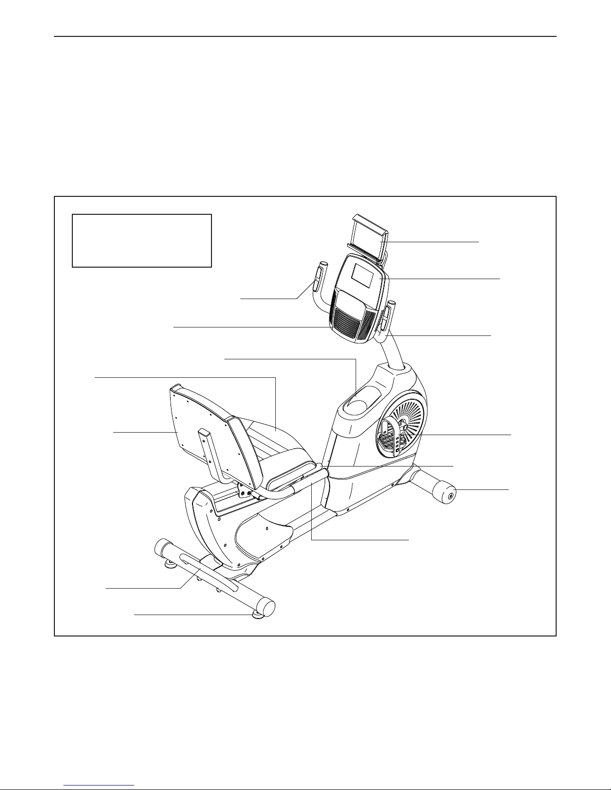
Heart Rate Monitor
Fan
Accessory Tray
reading this manual, please see the front cover of this
manual. To help us assist you, note the product model
number and serial number before contacting us. The
model number and the location of the serial number
decal are shown on the front cover of this manual.
Before reading further, please familiarize yourself with
the parts that are labeled in the drawing below.
Tablet Holder
Console
Handlebar
Seat
Backrest
Handle
Leveling Foot
Pedal
Adjustment Handle
Wheel
Handlebar
4
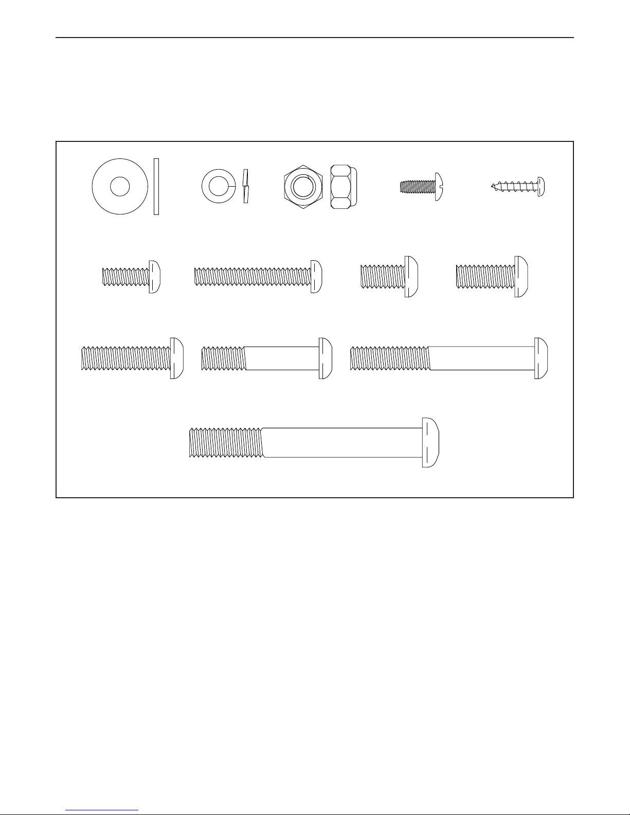
PART IDENTIFICATION CHART
Use the drawings below to identify the small parts needed for assembly. The number in parentheses below each
drawing is the key number of the part, from the PART LIST near the end of this manual. The number following the
key number is the quantity needed for assembly. Note: If a part is not in the hardware kit, check to see if it
has been preassembled. Extra parts may be included.
M6 Washer (35)–2
M6 x 16mm
Screw (33)–2
M8 x 30mm
Screw (41)–1
M6 Split
Washer (34)–2
M6 x 40mm
Screw (27)–6
M8 x 40mm
Screw (28)–4
M8 Locknut
(25)–2
M8 x 15mm
Screw (24)–4
M10 x 80mm Screw (21)–4
M4 x 12mm
Machine
Screw (18)–4
M8 x 63mm Bolt
(26)–2
M4 x 16mm
Screw (49)–6
M8 x 20mm
Screw (42)–1
5
ASSEMBLY
• Assembly requires two persons.
• Place all parts in a cleared area and remove the
packing materials. Do not dispose of the packing
materials until you nish all assembly steps.
• Left parts are marked “L” or “Left” and right parts
are marked “R” or “Right.”
• To identify small parts, see page 5.
1. Go to www.iconsupport.eu on your computer
and register your product.
• activates your warranty
• saves you time if you ever need to contact
Customer Service
• allows us to notify you of upgrades and offers
Note: If you do not have internet access, call
Customer Service (see the front cover of this
manual) and register your product.
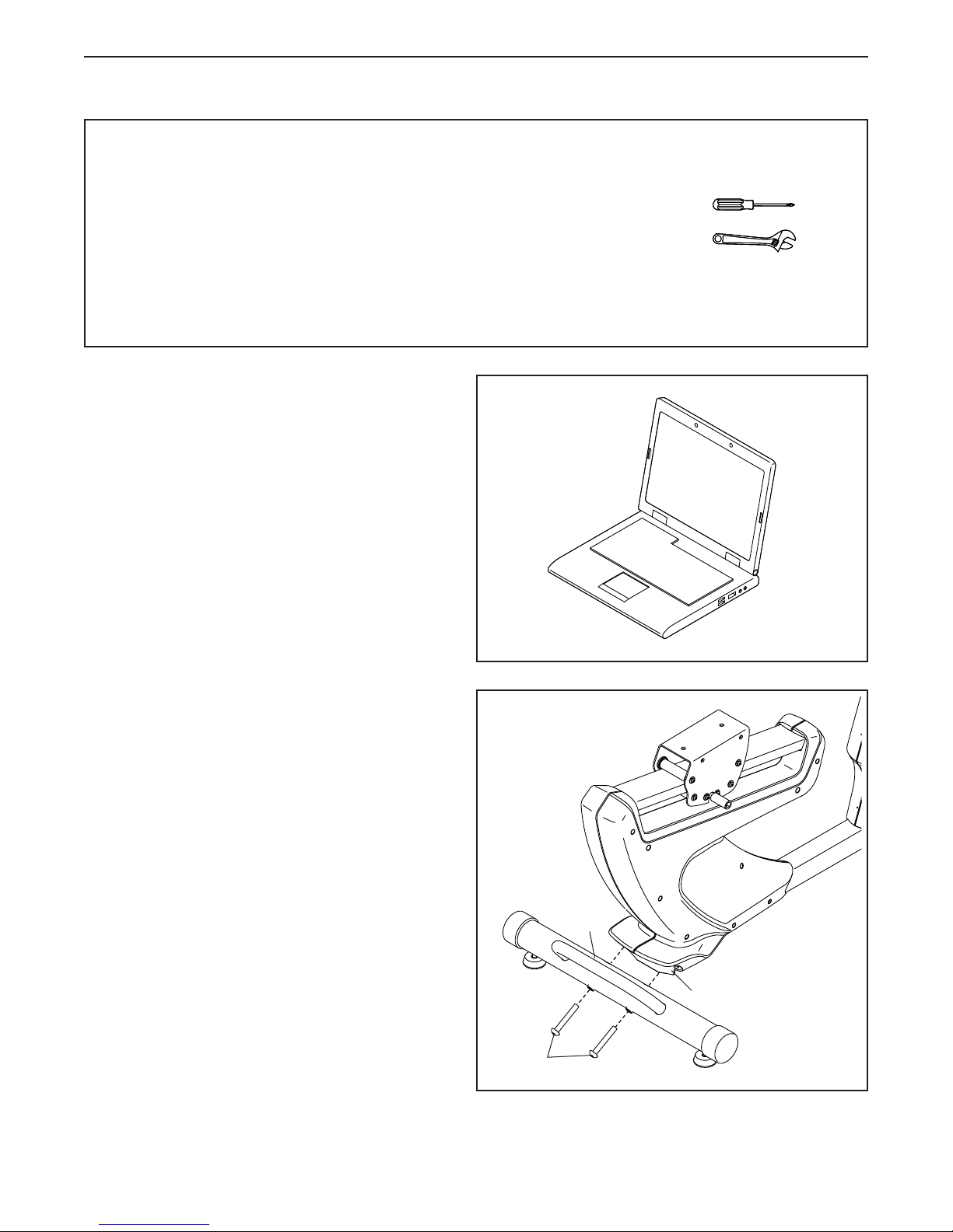
In addition to the included tool(s), assembly
requires the following tools:
one Phillips screwdriver
one adjustable wrench
Assembly may be easier if you have a set of
wrenches. To avoid damaging parts, do not use
power tools.
1
2. Orient the Rear Stabilizer (3) as shown.
While a second person lifts the rear of the Frame
(1), attach the Rear Stabilizer (3) to the Frame
with two M10 x 80mm Screws (21).
2
3
1
21
6
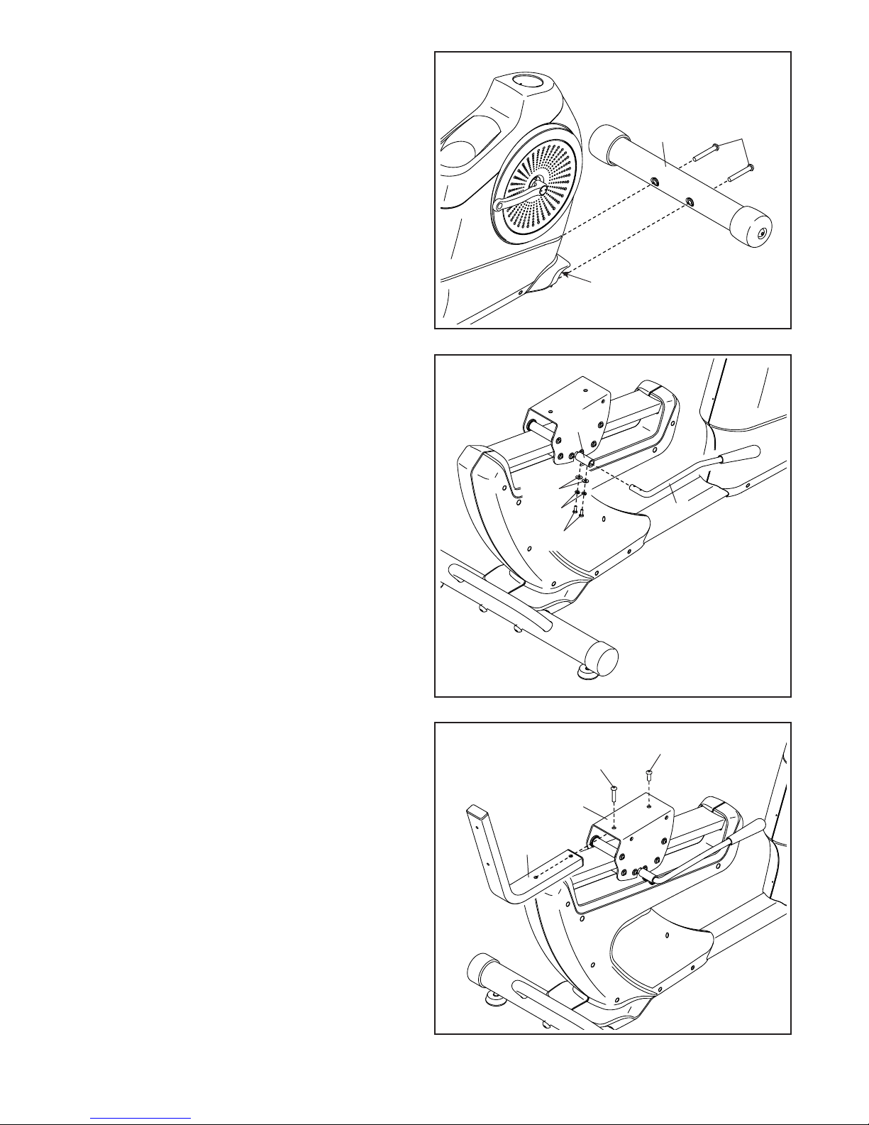
3. Orient the Front Stabilizer (2) as indicated by the
sticker.
While a second person lifts the front of the
Frame (1), attach the Front Stabilizer (2) to the
Frame with two M10 x 80mm Screws (21).
3
2
1
21
4. Orient the Adjustment Lever (6) as shown.
Attach the Adjustment Lever (6) to the Brake
Axle (37) with two M6 x 16mm Screws (33),
two M6 Split Washers (34), and two M6
Washers (35).
5. Orient the Backrest Frame (8) as shown.
Attach the Backrest Frame (8) to the Seat
Carriage (7) with an M8 x 20mm Screw (42) and
an M8 x 30mm Screw (41).
4
37
35
34
33
5
41
7
6
42
8
7

6. Orient the Seat (10) and the Seat Frame (9) as
shown.
Attach the Seat (10) to the Seat Frame (9) with
four M6 x 40mm Screws (27); start all the
Screws, and then tighten them.
6
10
9
27
27
7. Attach the Seat Frame (9) to the Seat Carriage
(7) with four M8 x 40mm Screws (28); start all
the Screws, and then tighten them.
7
28
9
7
28
8
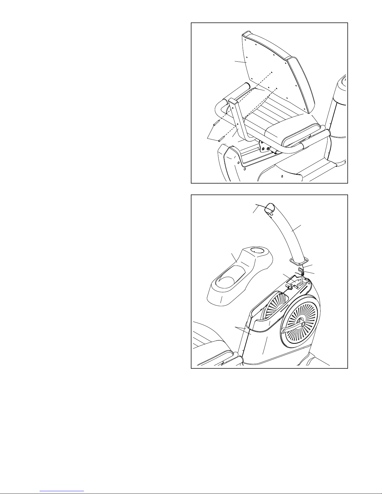
8. Orient the Backrest (11) as shown.
Attach the Backrest (11) to the Backrest Frame
(8) with two M6 x 40mm Screws (27).
8
11
9. Remove the Accessory Tray (5) from the Left
and Right Front Shields (57, 58). Set the
Accessory Tray aside. Tip: It may be necessary
to use a standard screwdriver to release the
tabs on the Accessory Tray.
Have a second person hold the Upright (4) near
the Frame (1).
Locate the wire tie (A) inside the Upright (4). Tie
the lower end of the wire tie to the Main Wire
(77). Then, pull the other end of the wire tie
upward until the Main Wire is routed through the
Upright.
Tip: To prevent the Main Wire (77) from falling
into the Upright (4), secure it to the Upright
with the wire tie (A).
27
9
8
5
57, 58
A
4
A
1
77
9
 Loading...