


nordictrack.com
Model No. NTEX89918.0
Serial No.
Write the serial number in the
space above for reference.
Serial Number
Decal
ACTIVATE YOUR
WARRANTY
To register your product and
activate your warranty today,
go to my.nordictrack.com.
CUSTOMER CARE
USER’S MANUAL
For service at any time, go to
nordictrackservice.com.
Or call 1-800-TO-BE-FIT
(1-800-862-3348)
Mon.–Fri. 6 a.m.–6 p.m. MT
Sat. 8 a.m.–12 p.m. MT
Please do not contact the store.
CAUTION
Read all precautions and instructions in this manual before using
this equipment. Keep this manual
for future reference.
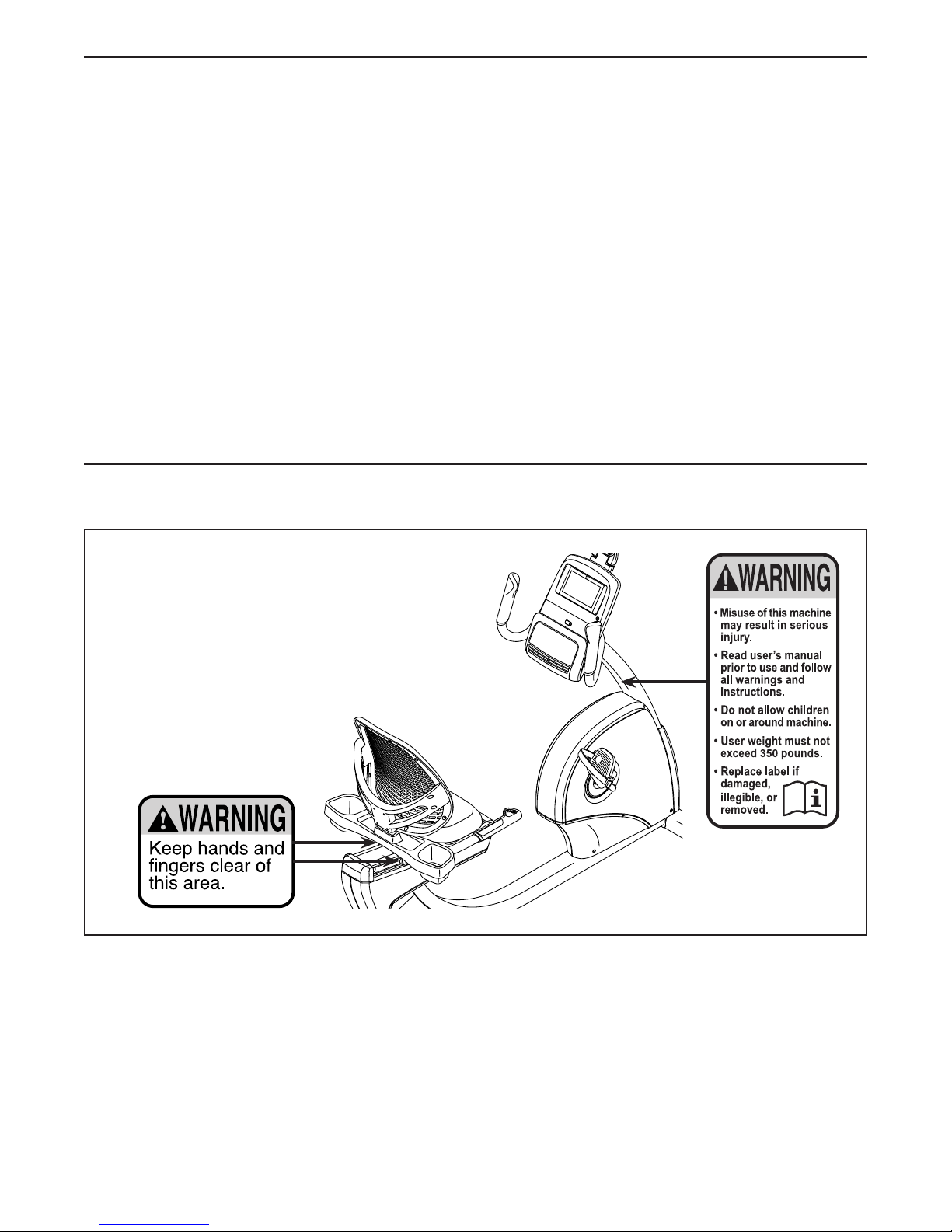
TABLE OF CONTENTS
WARNING DECAL PLACEMENT . . . . . . . . . . . . . . . . . . . . . . . . . . . . . . . . . . . . . . . . . . . . . . . . . . . . . . . . . . . . . . .2
IMPORTANT PRECAUTIONS ..................................................................3
BEFORE YOU BEGIN. . . . . . . . . . . . . . . . . . . . . . . . . . . . . . . . . . . . . . . . . . . . . . . . . . . . . . . . . . . . . . . . . . . . . . . .5
PART IDENTIFICATION CHART. . . . . . . . . . . . . . . . . . . . . . . . . . . . . . . . . . . . . . . . . . . . . . . . . . . . . . . . . . . . . . . .6
ASSEMBLY . . . . . . . . . . . . . . . . . . . . . . . . . . . . . . . . . . . . . . . . . . . . . . . . . . . . . . . . . . . . . . . . . . . . . . . . . . . . . . . .7
THE CHEST HEART RATE MONITOR. . . . . . . . . . . . . . . . . . . . . . . . . . . . . . . . . . . . . . . . . . . . . . . . . . . . . . . . . .15
HOW TO USE THE EXERCISE BIKE. . . . . . . . . . . . . . . . . . . . . . . . . . . . . . . . . . . . . . . . . . . . . . . . . . . . . . . . . . . 16
FCC INFORMATION . . . . . . . . . . . . . . . . . . . . . . . . . . . . . . . . . . . . . . . . . . . . . . . . . . . . . . . . . . . . . . . . . . . . . . . .27
MAINTENANCE AND TROUBLESHOOTING .....................................................28
EXERCISE GUIDELINES ....................................................................30
PART LIST. . . . . . . . . . . . . . . . . . . . . . . . . . . . . . . . . . . . . . . . . . . . . . . . . . . . . . . . . . . . . . . . . . . . . . . . . . . . . . . .32
EXPLODED DRAWING. . . . . . . . . . . . . . . . . . . . . . . . . . . . . . . . . . . . . . . . . . . . . . . . . . . . . . . . . . . . . . . . . . . . . .34
ORDERING REPLACEMENT PARTS .................................................. Back Cover
LIMITED WARRANTY. . . . . . . . . . . . . . . . . . . . . . . . . . . . . . . . . . . . . . . . . . . . . . . . . . . . . . . . . . . . . . . Back Cover
WARNING DECAL PLACEMENT
This drawing shows the location(s) of the warning
decal(s). If a decal is missing or illegible, see
the front cover of this manual and request a
free replacement decal. Apply the decal in the
location shown. Note: The decal(s) may not be
shown at actual size.
NORDICTRACK and IFIT are registered trademarks of ICON Health & Fitness, Inc. The BLUETOOTH® word
mark and logos are registered trademarks of Bluetooth SIG, Inc. and are used under license. Google Maps is a
trademark of Google Inc. Wi-Fi is a registered trademark of Wi-Fi Alliance. WPA and WPA2 are trademarks of
Wi-Fi Alliance.
2

IMPORTANT PRECAUTIONS
WARNING: To reduce the risk of serious injury, read all important precautions and
instructions in this manual and all warnings on your exercise bike before using your exercise bike.
ICON assumes no responsibility for personal injury or property damage sustained by or through the
use of this product.
1. It is the responsibility of the owner to ensure
that all users of the exercise bike are adequately informed of all precautions.
2. Before beginning any exercise program,
consult your physician. This is especially
important for persons over age 35 or persons with pre-existing health problems.
3. The exercise bike is not intended for use by
persons with reduced physical, sensory, or
mental capabilities or lack of experience and
knowledge, unless they are given supervision or instruction about use of the exercise
bike by someone responsible for their safety.
4. Use the exercise bike only as described in
this manual.
5. The exercise bike is intended for home use
only. Do not use the exercise bike in a commercial, rental, or institutional setting.
6. Keep the exercise bike indoors, away from
moisture and dust. Do not put the exercise
bike in a garage or covered patio, or near
water.
7. Place the exercise bike on a level surface
with at least 2 ft. (0.6 m) of clearance around
the exercise bike. To protect the floor or
carpet from damage, place a mat under the
exercise bike.
8. Inspect and properly tighten all parts each
time the exercise bike is used. Replace any
worn parts immediately.
9. Keep children under age 13 and pets away
from the exercise bike at all times.
10. Wear appropriate clothes while exercising;
do not wear loose clothes that could become
caught on the exercise bike. Always wear
athletic shoes for foot protection.
11. The exercise bike should not be used
by persons weighing more than 350 lbs.
(159 kg).
12. Be careful when mounting and dismounting
the exercise bike.
13. The heart rate monitor is not a medical
device. Various factors, including the user’s
movement, may affect the accuracy of heart
rate readings. The heart rate monitor is
intended only as an exercise aid in determining heart rate trends in general.
14. Always keep your back straight while using
the exercise bike; do not arch your back.
15. Over exercising may result in serious injury
or death. If you feel faint, if you become short
of breath, or if you experience pain while
exercising, stop immediately and cool down.
3

STANDARD SERVICE PLANS
all
4
BEFORE YOU BEGIN
Thank you for selecting the revolutionary
NORDICTRACK® VR 25 exercise bike. Cycling is an
effective exercise for increasing cardiovascular tness,
building endurance, and toning the body. The VR 25
exercise bike provides an impressive selection of features designed to make your workouts at home more
effective and enjoyable.
For your benet, read this manual carefully before
you use the exercise bike. If you have questions after
Length: 5 ft. 8 in. (173 cm)
Width: 1 ft. 10 in. (56 cm)
Fan
reading this manual, please see the front cover of this
manual. To help us assist you, note the product model
number and serial number before contacting us. The
model number and the location of the serial number
decal are shown on the front cover of this manual.
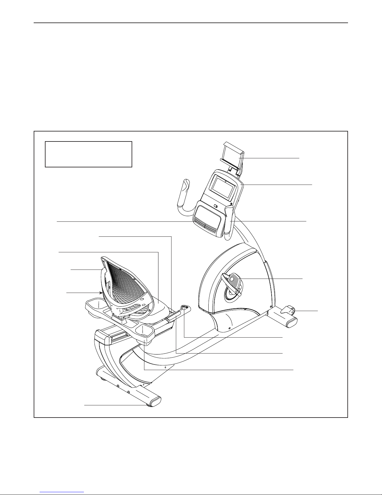
Before reading further, please familiarize yourself with
the parts that are labeled in the drawing below.
Tablet Holder
Console
Handlebar
Adjustment Handle
Seat
Backrest
Volume
Control
Leveling Foot
Pedal/Strap
Wheel
Resistance Control
Heart Rate Monitor
Accessory Tray
5
PART IDENTIFICATION CHART
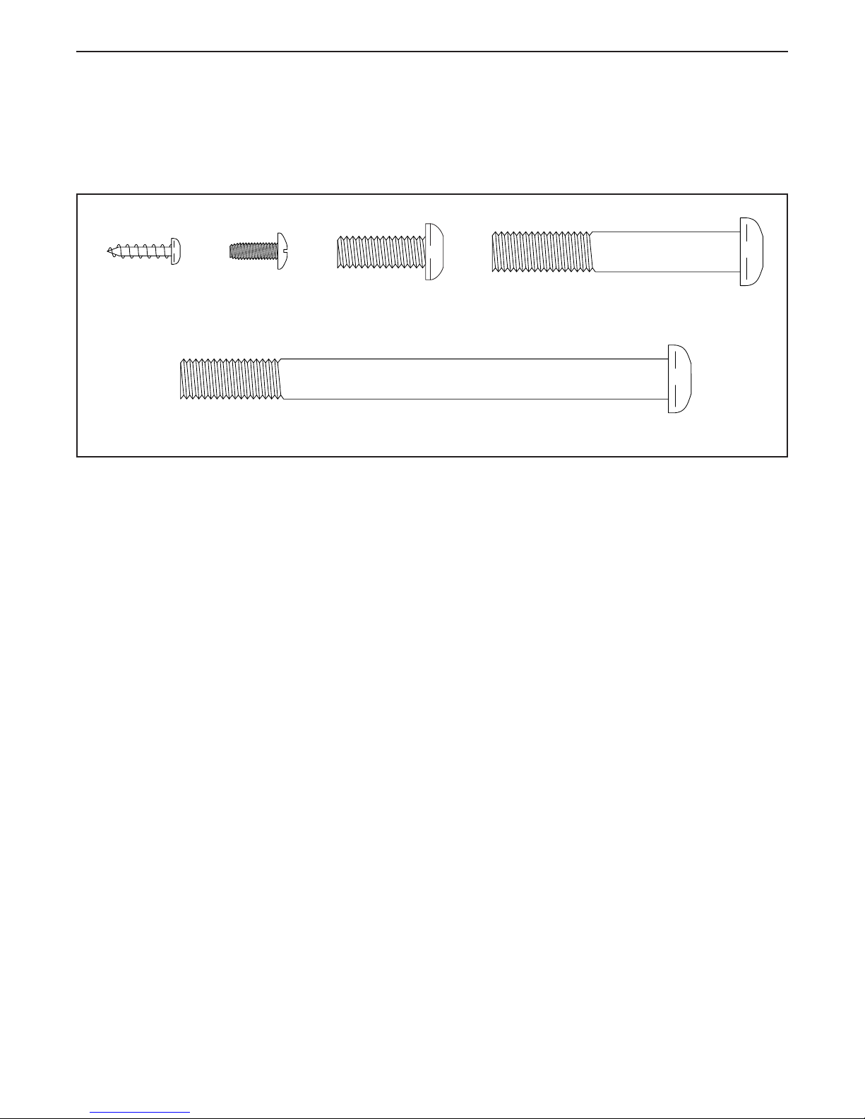
Use the drawings below to identify the small parts needed for assembly. The number in parentheses below each
drawing is the key number of the part, from the PART LIST near the end of this manual. The number following the
key number is the quantity needed for assembly. Note: If a part is not in the hardware kit, check to see if it
has been preassembled. Extra parts may be included.
M4 x 16mm
Screw (77)–6
Tablet Holder
Screw (54)–4
M8 x 22mm
Screw (69)–2
M10 x 122mm Screw (65)–4
M10 x 62mm Screw (70)–4
6
ASSEMBLY
• Assembly requires two persons.
• Place all parts in a cleared area and remove the
packing materials. Do not dispose of the packing
materials until you nish all assembly steps.
• Left parts are marked “L” or “Left” and right parts
are marked “R” or “Right.”
• To identify small parts, see page 6.
1. Go to my.nordictrack.com on your computer
and register your product.
• documents your ownership
• activates your warranty
• ensures priority customer support if assistance
is ever needed
Note: If you do not have internet access, call
Customer Care (see the front cover of this
manual) and register your product.
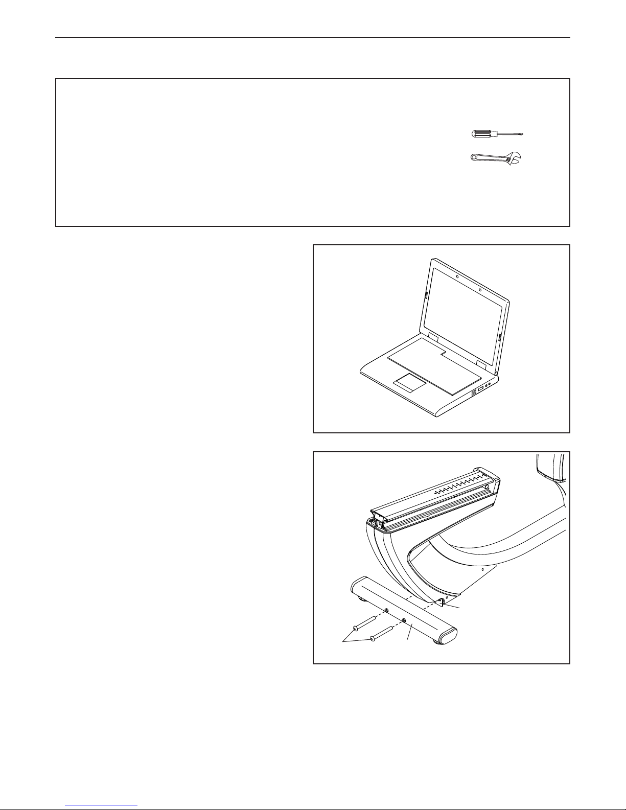
In addition to the included tool(s), assembly
requires the following tools:
one Phillips screwdriver
one adjustable wrench
Assembly may be easier if you have a set of
wrenches. To avoid damaging parts, do not use
power tools.
1
2. Set a sturdy piece of packing material under the
rear of the Frame (1). Have a second person
hold the Frame to prevent it from tipping
while you complete this step.
Orient the Rear Stabilizer (16) as indicated by
the sticker. Attach the Rear Stabilizer to the
Frame (1) with two M10 x 122mm Screws (65).
Then, remove the packing material.
2
1
65
16
7
3. Set a sturdy piece of packing material under the
front of the Frame (1). Have a second person
hold the Frame to prevent it from tipping
while you complete this step.
Orient the Front Stabilizer (15) as shown. Attach
the Front Stabilizer to the Frame (1) with two
M10 x 122mm Screws (65).
3
65
Then, remove the packing material.
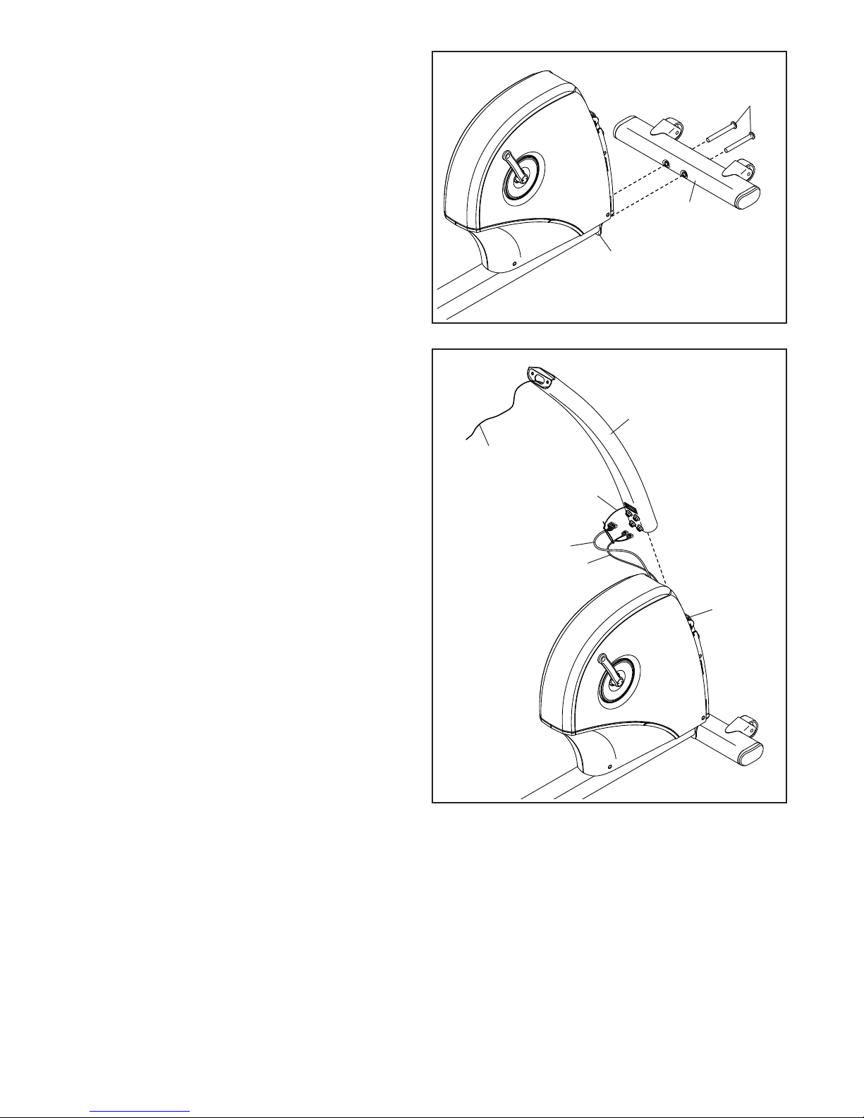
4. Orient the Upright (2) as shown. Have a second
person hold the Upright near the front of the
Frame (1).
Tie the lower end of the wire tie (A) in the Upright
(2) to the Main Wire (43) and to the Frame Pulse
Wire (42) in the Frame (1).
Then, pull the upper end of the wire tie (A)
until the Wires (42, 43) are routed through the
Upright (2).
15
1
4
2
A
A
43
42
1
8
5. Tip: Avoid pinching the wires. Slide the
Upright (2) onto the Frame (1).
Attach the Upright (2) with four M10 x 62mm
Screws (70); start all the Screws, and then
tighten them.
5
Avoid pinching
the wires
2
70
1
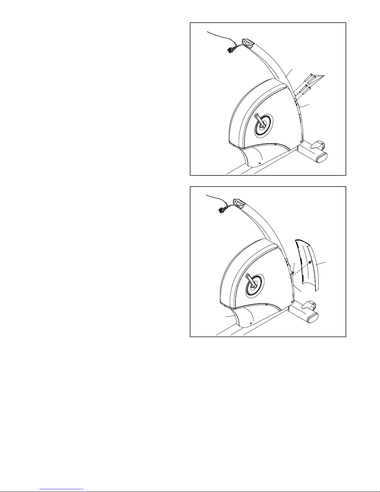
6. Press the mount on the Front Shield (58) into the
Frame (1). Then, press the Front Shield onto the
Left and Right Front Shields (13, 14).
6
1
14
13
58
9
7. Orient the Upright Cover (57) as shown. Hold the
Upright Cover near the Upright (2), and insert
the wire tie (A) and the wires (B) upward through
the Upright Cover.
Then, slide the Upright Cover (57) onto the
Upright (2).
7
2
A
57
B
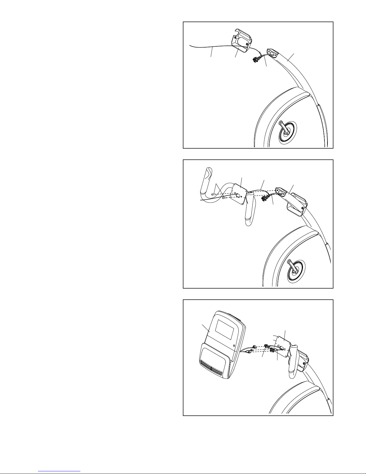
8. Orient the Handlebar (7) as shown. While a
second person holds the Handlebar near the
Upright (2), insert the wire tie (A) and the wires
(B) upward through the Handlebar.
Tip: Avoid pinching the wires. Attach the
Handlebar (7) to the Upright (2) with two
M8 x 22mm Screws (69).
9. Untie and discard the wire tie on the Main Wire
(43) and the Frame Pulse Wires (42).
While a second person holds the Console (4)
near the Handlebar (7), connect the wires on the
Console to the Main Wire (43) and the Frame
Pulse Wires (42).
8
69
Avoid pinching
the wires
9
4
7
A
2
B
7
Insert the excess wire into the Handlebar (7).
Tip: It may be helpful to insert the connectors
on the wires one at a time through the hole in
the Handlebar.
10
43
42
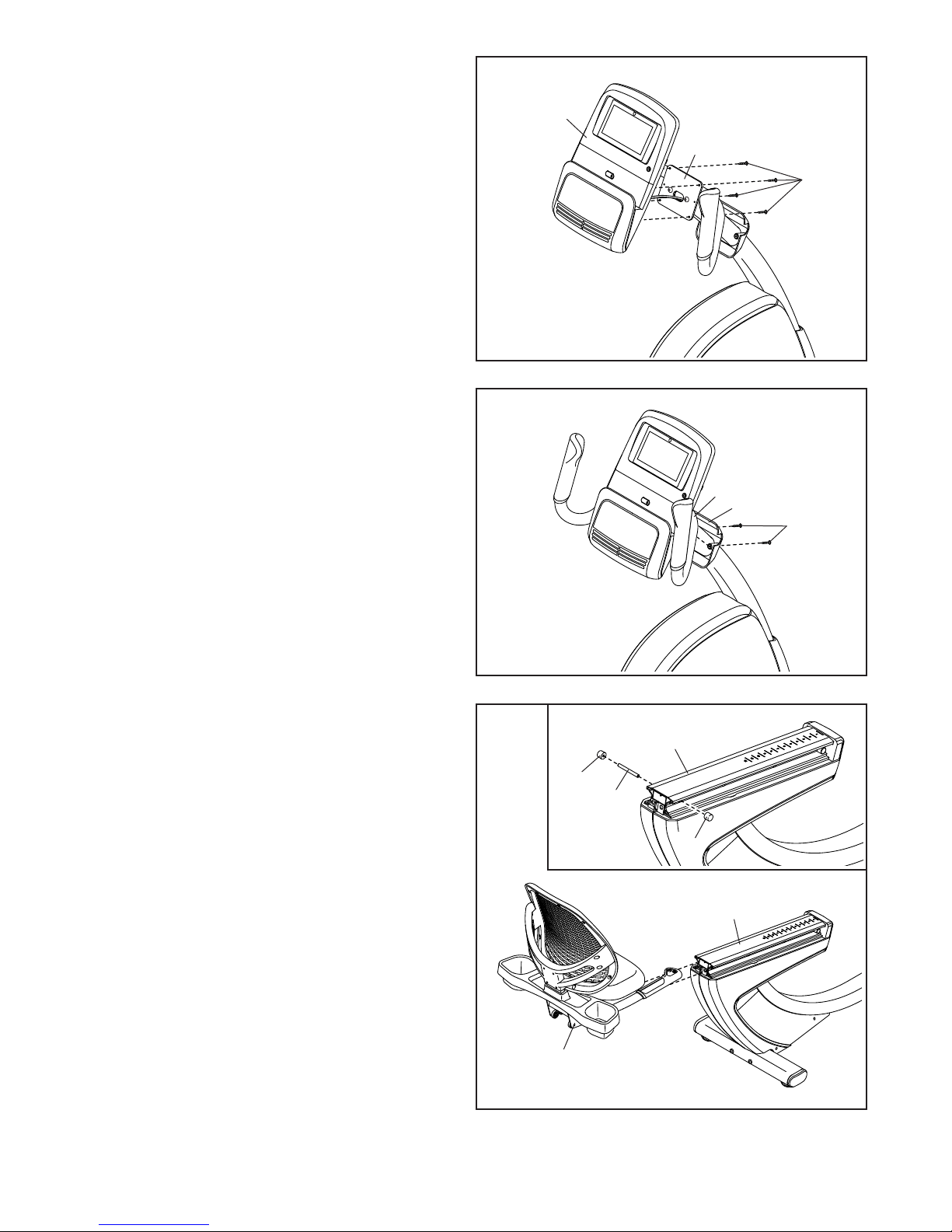
10. Tip: Avoid pinching the wires. Attach the
Console (4) to the Handlebar (7) with four
M4 x 16mm Screws (77); start all the Screws,
and then tighten them.
10
4
7
77
Avoid pinching
the wires
11. Attach the Upright Cover (57) to the Handlebar
(7) with two M4 x 16mm Screws (77).
12. See the inset drawing. Loosen and remove the
Rail Caps (62), and then remove the Rail Rod
(60) from the Rail (5). Set these parts aside
until step 13.
Orient the seat assembly as shown. Then, slide
the Seat Carriage (41) onto the Rail (5).
11
12
62
60
7
57
77
5
62
5
41
11
 Loading...