

NordicTrack Viewpoint 3000 NTL11806.0, Viewpoint 3000, NTL11806.0 User Manual
Model No. NTL11806.0
Serial No.
Write the serial number in the space
above for reference.
Serial Number /
Decal
QUESTIONS?
As a manufacturer, we are corn =
mitted to providing complete
customer satisfaction. If you
have questions, or if parts are
damaged or missing, PLEASE
CONTACT OUR CUSTOMER
SERVICE DEPARTMENT
DIRECTLY.
'S UAL
CALL TOLL=FREE:
1-888-825-2588
Mon.-Fri., 6 a.m.-6 p.m. MST
ON THE WEB:
www.nordictrackservice.com
www.nordictrack.com
new products, prizes,
fitness tips, and much more!

TABLE OF CONTENTS
iMPORTANT PRECAUTIONS ................................................................. 3
BEFORE YOU BEGIN ....................................................................... 6
ASSEMBLY ............................................................................... 7
OPERATION AND ADJUSTMENT ............................................................ 14
HOW TO FOLD AND MOVE THE TREADMILL .................................................. 27
TROUBLESHOOTING ...................................................................... 29
CONDiTiONiNG GUiDELiNES ............................................................... 32
PART LiST ............................................................................... 34
ORDERING REPLACEMENT PARTS .......................................................... 35
EXPLODED DRAWING ..................................................................... 36
LiMiTED WARRANTY ............................................................... Back Cover
NordicTrack is a registered trademark of iCON IP, inc.
2
iMPORTANT PRECAUTIONS
WARN ING: Toreducetheriskofburns,fire,eJectdcshock,or injury topersons,readthe
following important precautions and information before operating the treadmill.
1. it is the responsibility of the owner to ensure
that all users of this treadmill are adequately
informed of all warnings and precautions.
2. Use the treadmill only as described.
.
Place the treadmill on a level surface, with at
Jeast eight feet of clearance behind it and two
feet on each side. Do not place the treadmill
on any surface that blocks air openings. To
protect the floor or carpet from damage, place
a mat under the treadmill.
4. Keep the treadmill indoors, away from mois-
ture and dust. Do not put the treadmill in a
garage or covered patio, or near water.
5. Do not operate the treadmill where aerosol
products are used or where oxygen is being
administered.
6. Keep children under the age of 12 and pets
away from the treadmill at alatimes.
7. The treadmill should not be used by persons
weighing more than 350 pounds.
8. Never allow more than one person on the
treadmill at a time.
9. Wear appropriate exercise clothes when
using the treadmill. Do not wear loose cJothes
that could become caught in the treadmill.
AthJetic support cJothes are recommended for
both men and women. A/ways wear athletic
shoes.Never use the treadmi//withbare feet,
wearing only stockings,orinsandals.
10. When connecting the power cord (see page 14),
plug the power cord into a surge suppressor
(not included) and plug the surge suppressor
into a grounded circuit capable of carrying 15
or more amps. No other appliance should be on
the same circuit. Do not use an extension cord.
11. Use only a single-outlet surge suppressor that
meets all of the specifications described on
page 14. To purchase a surge suppressor, see
your local NordicTrack dealer or call the toll-
free telephone number on the front cover of
this manual and order part number 146148, or
see your local electronics store.
12. Failure to use a properly functioning surge
suppressor could result in damage to the con-
trol system of the treadmill, if the control sys-
tem is damaged, the walking belt may change
speed, accelerate, or stop unexpectedly,
which may result in a fall and serious injury.
13. Keep the power cord and the surge suppres-
sor away from heated surfaces.
14. Never move the walking belt while the power
is turned off. Do not operate the treadmill if
the power cord or plug is damaged, or if the
treadmill is not working properly. (See
TROUBLESHOOTING on page 29 if the tread-
mill is not working properly.)
15. Read, understand, and test the emergency
stop procedure before using the treadmill (see
HOW TO TURN ON THE POWER on page 16).
16. Never start the treadmill while you are stand-
ing on the walking belt. Always hold the
handrails while using the treadmill.
17. The treadmill is capable of high speeds.
Adjust the speed in small increments to avoid
sudden jumps in speed.
18. The pulse sensor is not a medical device.
Various factors, including the user's move-
ment, may affect the accuracy of heart rate
readings. The pulse sensor is intended only
as an exercise aid in determining heart rate
trends in general
19. Never leave the treadmill unattended while it
is running. Always remove the key, unplug the
power cord, and switch the reset/off circuit
breaker to the off position when the treadmill
is not in use. (See the drawing on page 6 for
the location of the reset/off circuit breaker.)
20. Do not attempt to raise, lower, or move the
treadmiJl until it is properly assembled. (See
ASSEMBLY on page 7, and HOW TO FOLD
AND MOVE THE TREADMILL on page 27.) You
must be able to safely lift 45 pounds (20 kg) to
raise, Jower, or move the treadmill.
3
21. Do not change the incline of the treadmill by
placing objects under the treadmill.
22. When folding or moving the treadmill, make
sure that the frame is held securely by the pin
on the latch knob.
or other electric light or power circuits, or
where it can fall into such power lines or cir-
cuits. When installing an outside antenna sys=
tern, extreme care should be taken to keep
from touching such power lines or circuits, as
contact with them might be fatal.
23. Inspect and properly tighten all parts of the
treadmiU regularly.
24. Never insert or drop any object into any
opening.
2s.DANGER: Alwaysunplugthepower
cord immediately after use, before cleaning
the treadmill, and before performing the main-
tenance and adjustment procedures de-
scribed in this manual. Never remove the
motor hood unless instructed to do so by an
authorized service representative. Servicing
other than the procedures in this manual
should be performed by an authorized service
representative only.
26. The treadmill is intended for in-home use
only. Do not use the treadmill in any commer=
cial, rental, or institutional setting.
27. If an outside antenna or cable system is con=
nected, be sure that the antenna or cable sys-
tem is grounded to provide some protection
against voltage surges and built=up static
charges. Section 810 of the National
Electrical Code, ANSI/NFPA No. 70-1984, pro-
vides information with respect to proper
grounding of the mast and supporting struc-
ture, grounding of the lead-in wire to an an=
tenna discharge unit, size of grounding con=
ductors, location of antenna discharge unit,
connection to grounding electrodes, and re-
quirements for the grounding electrode.
28. An outside antenna system should not be lo-
cated in the vicinity of overhead power lines
29. To reduce the risk of electric shock, do not re-
move the cover or the back of the television.
There are no user serviceable parts inside.
Refer servicing to qualified service personnel.
30. Upon completion of any service or repairs to
the treadmill or the television, ask the service
technician to perform safety checks to con-
firm that the unit is in proper operating con-
dition.
Use No. 10 AWG (5.3ram 2)copper, No. 8
AWG (8.4ram 2)aluminum, No. 17 AWG
(1.0ram 2)copper-clad steel or bronze wire,
or larger as a ground wire.
Secure an antenna lead-in and ground wires
to the house with stand-off insulators
spaced from 4 to 6 feet (1.22 to 1.83m)
apart.
Mount an antenna discharge unit as close
as possible to where the lead-in enters the
house.
Use a jumper wire not smaller than No. 6
AWG (13.3mm 2)copper, or the equivalent
when a separate antenna-grounding elec-
trode is used. See NEC Section 810-21 (j).
Note to CATV system installer: This reminder is
provided to call the CATV system instailer's at=
tention to Article 820-40 of the NEC that provides
guidelines for proper grounding and, in particu-
lar, specifies that the cable ground shah be con-
nected to the grounding system of the building,
as close to the point of cable entry as practical
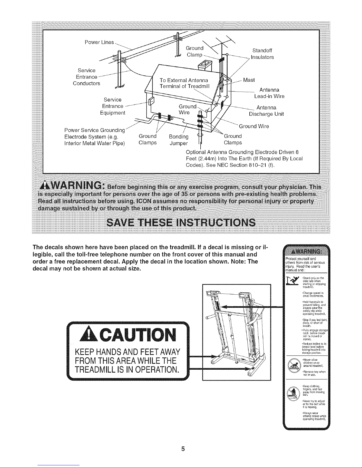
Ground Standoff
Clam Insulators
Service
To External Antenna
Conductors Terminal of Treadmill Antenna
Service Lead-in Wire
Entrance Antenna
Equipment Wire Discharge Unit
iiiiiiiiiiiiiiiiiiii
Power Service Grounding
Ground Wire
Electrode System (e.g. Ground Bonding 3round
Interior Metal Water Pipe) Clamps Jumper Clamps
Optional Antenna Grounding Electrode Driven 8
Feet (2.44m) Into The Earth (If Required By Local
Codes). See NEC Section 810-21 (f).
The decals shown here have been placed on the treadmill, if a decal is missing or il=
legible, call the toll-free telephone number on the front cover of this manual and
order a free replacement decal. Apply the decal in the location shown. Note: The
decal may not be shown at actual size.
CAUTION
KEEP HANDSAND FEETAWAY
FROM THIS AREA WHILE THE
TREADMILLISINOPERATION.
m
m
Protect yourself and
others from risk of serious
injury. Read the user's
manual and :
side rails when
-Stalld only on the
start ng or stopping
treadmill,
-Change speed in
small it_crements,
'Hold handrails to
prevent falling, and
always wear the
safety clip while
operating treadmill,
-Stop if you feel faint,
dizzy, or short of
b[eath.
mill s moved or
stored,
•Redt_ce incline to its
lowest level before
•Never allow
children on o[
around treadmill,
,Remove key when
not _ use,
_fis moving,
,Always wear
athletic shoes while
operating treadmill.
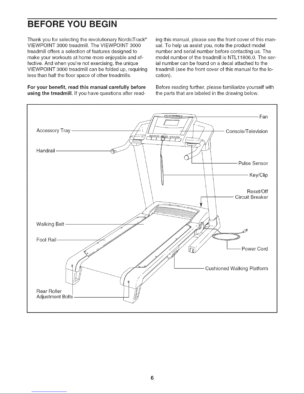
BEFORE YOU BEGIN
Thank you for selecting the revolutionary NordicTrack ®
VIEWPOINT 3000 treadmill. The VIEWPOINT 3000
treadmill offers a selection of features designed to
make your workouts at home more enjoyable and ef-
fective. And when you're not exercising, the unique
VIEWPOINT 3000 treadmill can be folded up, requiring
less than half the floor space of other treadmills.
For your benefit, read this manual carefully before
using the treadmill, if you have questions after read-
Accessory Tray
Handrail
ing this manual, please see the front cover of this man-
ual. To help us assist you, note the product model
number and serial number before contacting us. The
model number of the treadmill is NTL11806.0. The ser-
ial number can be found on a decal attached to the
treadmill (see the front cover of this manual for the lo-
cation).
Before reading further, please familiarize yourself with
the parts that are labeled in the drawing below.
Fan
-- Console/Television
Pulse Sensor
Key/Clip
Walking Belt
Foot Rail
Rear Roller
Adjustment Bolts
Reset/Off
Circuit Breaker
-- Power Cord
Cushioned Walking Platform
6

ASSEMBLY
Assembly requires two persons. Set the treadmill in a cleared area and remove all packing materials. Do not
dispose of the packing materials until assembly is completed.
Note: The underside of the treadmill walking belt is coated with high-performance lubricant. During shipping, a
small amount of lubricant may be transferred to the top of the walking belt or the shipping carton. This is a normal
condition and does not affect treadmill performance. If there is lubricant on top of the walking belt, simply wipe off
the lubricant with a soft cloth and a mild, non-abrasive cleaner.
Assembly requires the included hex key _ and your own phillips screwdriver _ , rubber
mallet _ and adjustable wrench __. For help identifying the assembly hardware, see
the drawings below. The number in parentheses below each drawing isthe key number of the part, from the
PART LIST on pages 34 and 35. The number following the parentheses is the quantity needed for assembly.
Note: Some small parts may have been preassembled. If a part is not in the parts bag, check to see if it has
been preassembled. To avoid damaging plastic parts, do not use power tools for assembly. Extra hard=
ware may be included.
[
5/16" Star
Nut (20)-2
3/4" Screw (7)-6
Console Bolt (72)-4 Latch Bolt (109)-2
1. Make sure that the power cord is unplugged.
With the help of a second person, carefully tip
the treadmill onto its side as shown. Partially fold
the Frame (55) so that the treadmill is more sta-
ble. Do not fully fold the Frame until the
treadmill is completely assembled.
Insert an Extension Leg (97) into the indicated
bracket on the base of the Uprights (85). Make
sure that the Extension Leg is turned so the Base
Pad (81) is on the side shown. If necessary, use
a rubber mallet to align the holes in the
Extension Leg with the holes in the bracket.
Washer (110)-4
1"Tek Screw (82)-8
3/8" Star
Washer (67)-4
Extension Leg
Nut (91)-4
Base Cover Screw (63)-4
Extension Leg Bolt (87)-4
Attach the Extension Leg (97) with two Extension
Leg Bolts (87), two 5/16" Star Washers (110),
and two Extension Leg Nuts (91) as shown.
Firmly tighten the Extension Leg Bolts.
97
81
55
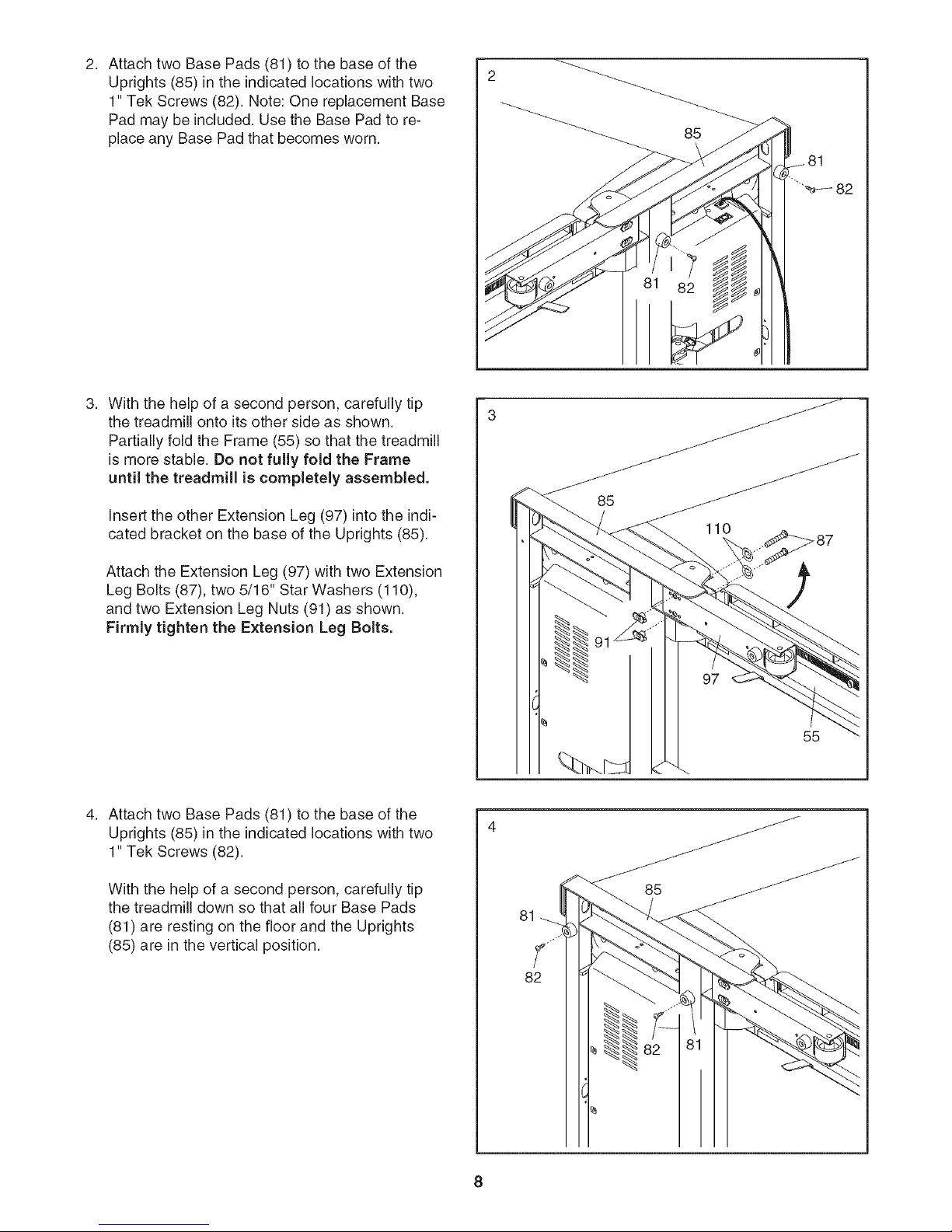
AttachtwoBasePads(81)tothebaseofthe
Uprights(85)intheindicatedlocationswithtwo
1"TekScrews(82).Note:OnereplacementBase
Padmaybeincluded.UsetheBasePadtore-
placeanyBasePadthatbecomesworn.
Withthehelpofa secondperson,carefullytip
thetreadmillontoitsothersideasshown.
PartiallyfoldtheFrame(55)sothatthetreadmill
is more stable. Do not fully fold the Frame
until the treadmill is completely assembled.
Insert the other Extension Leg (97) into the indi-
cated bracket on the base of the Uprights (85).
85
_81
"_--- 82
Attach the Extension Leg (97) with two Extension
Leg Bolts (87), two 5/16" Star Washers (110),
and two Extension Leg Nuts (91) as shown.
Firmly tighten the Extension Leg Bolts.
Attach two Base Pads (81) to the base of the
Uprights (85) in the indicated locations with two
1" Tek Screws (82).
With the help of a second person, carefully tip
the treadmill down so that all four Base Pads
(81) are resting on the floor and the Uprights
(85) are in the vertical position.
55
85
81
S
82
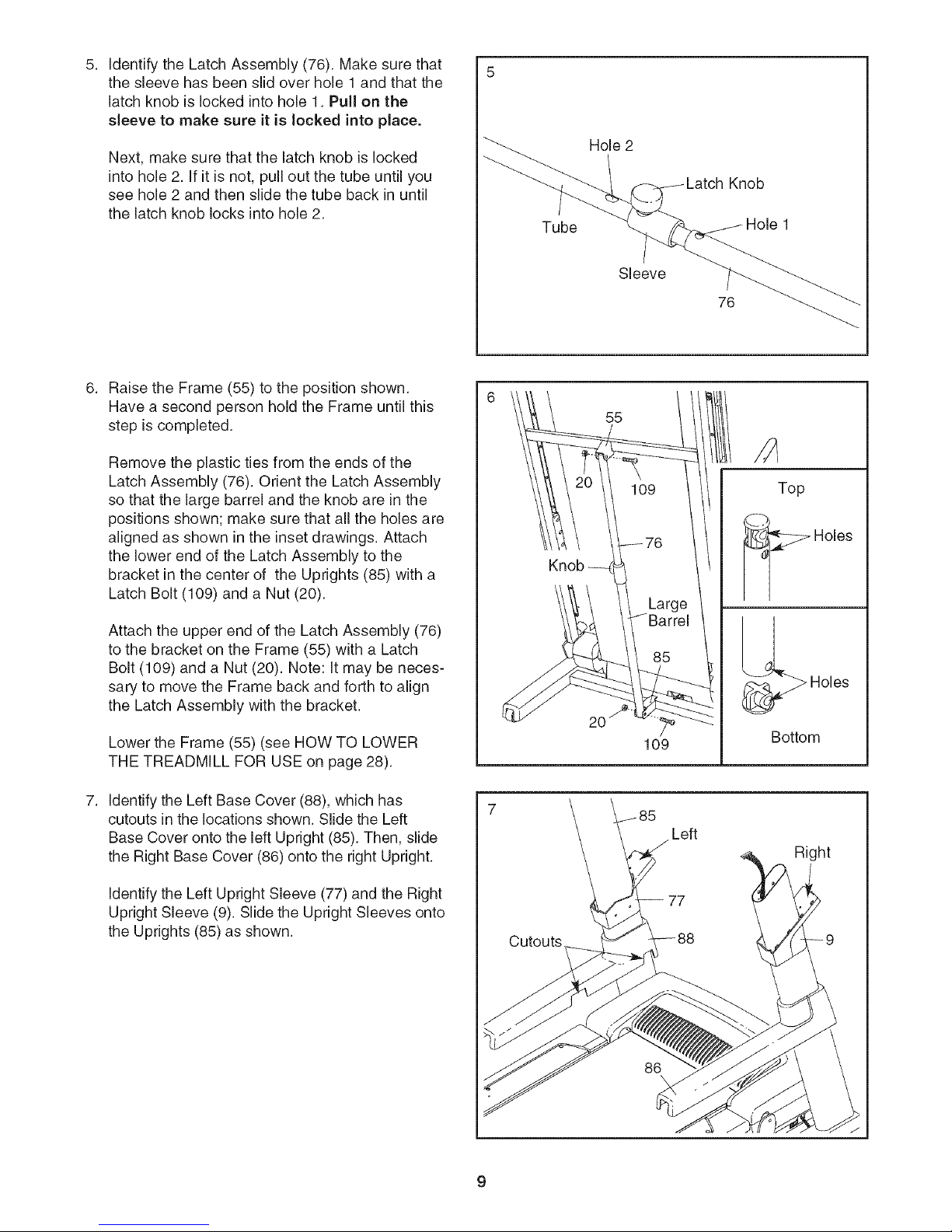
IdentifytheLatchAssembly(76).Makesurethat
thesleevehasbeenslidoverhole1andthatthe
latchknobislockedintohole1.Pullonthe
sleeve to make sure it is locked into place.
Next, make sure that the latch knob is locked
into hole 2. If it is not, pull out the tube until you
see hole 2 and then slide the tube back in until
the latch knob locks into hole 2.
Raise the Frame (55) to the position shown.
Have a second person hold the Frame until this
step is completed.
Remove the plastic ties from the ends of the
Latch Assembly (76). Orient the Latch Assembly
so that the large barrel and the knob are in the
positions shown; make sure that all the holes are
aligned as shown in the inset drawings. Attach
the lower end of the Latch Assembly to the
bracket in the center of the Uprights (85) with a
Latch Bolt (109) and a Nut (20).
Tube
Knob
Hole 2
Knob
Sleeve
76
55
Top
Holes
/Large
Attach the upper end of the Latch Assembly (76)
to the bracket on the Frame (55) with a Latch
Bolt (109) and a Nut (20). Note: It may be neces-
sary to move the Frame back and forth to align
the Latch Assembly with the bracket.
Lower the Frame (55) (see HOW TO LOWER
THE TREADMILL FOR USE on page 28).
Identifythe Left Base Cover (88), which has
cutouts in the locations shown. Slide the Left
Base Cover onto the left Upright (85). Then, slide
the Right Base Cover (86) onto the right Upright.
Identifythe Left Upright Sleeve (77) and the Right
Upright Sleeve (9). Slide the Upright Sleeves onto
the Uprights (85) as shown.
Cutouts
109
Holes
Bottom
Left
Right
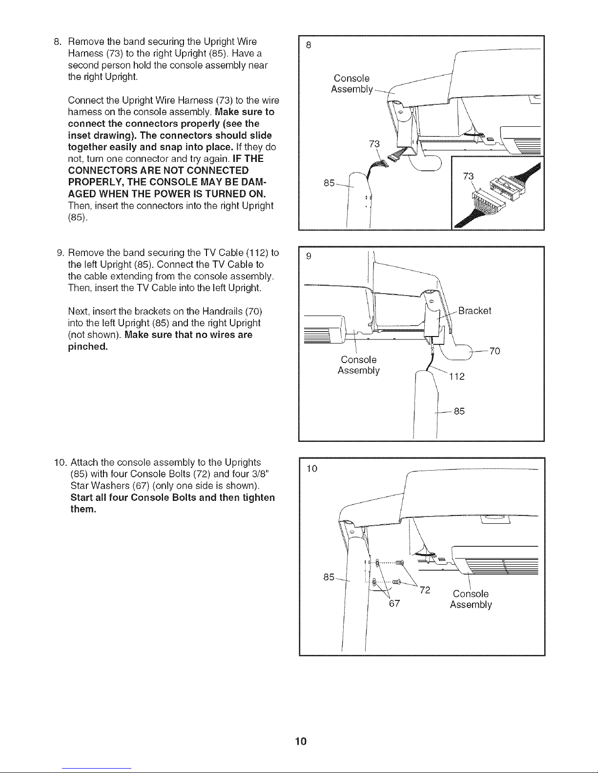
RemovethebandsecuringtheUprightWire
8. 8
Harness(73)totherightUpright(85).Havea
secondpersonholdtheconsoleassemblynear
therightUpright.
ConnecttheUprightWireHarness(73)tothewire
harnessontheconsoleassembly.Make sure to
connect the connectors properly (see the
inset drawing). The connectors should slide
together easily and snap into place, if they do
not, turn one connector and try again. IF THE
CONNECTORS ARE NOT CONNECTED
PROPERLY, THE CONSOLE MAY BE DAM=
AGED WHEN THE POWER IS TURNED ON.
Then, insert the connectors into the right Upright
(85).
9. Remove the band securing the TV Cable (112) to
the left Upright (85). Connect the TV Cable to
the cable extending from the console assembly.
Then, insert the TV Cable into the left Upright.
Next, insert the brackets on the Handrails (70)
into the left Upright (85) and the right Upright
(not shown). Make sure that no wires are
pinched.
Console
Assembl'
73
Console
Assembly
10. Attach the console assembly to the Uprights
(85) with four Console Bolts (72) and four 3/8"
Star Washers (67) (only one side is shown).
Start all four Console Bolts and then tighten
them.
2
85
10
67 Assembly
10
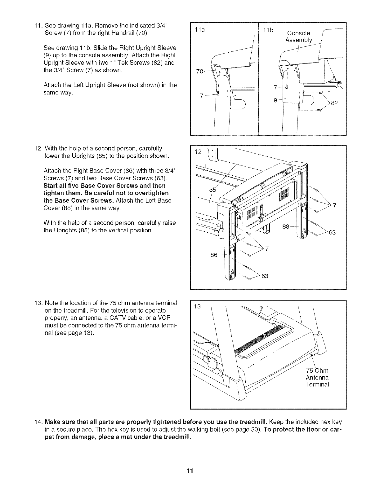
11. See drawing 1la. Remove the indicated 3/4"
Screw (7) from the right Handrail (70).
See drawing 1lb. Slide the Right Upright Sleeve
(9) up to the console assembly. Attach the Right
Upright Sleeve with two 1" Tek Screws (82) and
the 3/4" Screw (7) as shown.
Attach the Left Upright Sleeve (not shown) in the
same way.
12 With the help of a second person, carefully
lower the Uprights (85) to the position shown.
Attach the Right Base Cover (86) with three 3/4"
Screws (7) and two Base Cover Screws (63).
Start all five Base Cover Screws and then
tighten them. Be careful not to overtighten
the Base Cover Screws. Attach the Left Base
Cover (88) in the same way.
11a
85
11b Console f_
7_
/
With the help of a second person, carefully raise
the Uprights (85) to the vertical position.
13. Note the location of the 75 ohm antenna terminal
on the treadmill For the television to operate
properly, an antenna, a CATV cable, or a VCR
must be connected to the 75 ohm antenna termi-
nal (see page 13).
63
63
75 Ohm
Antenna
Terminal
14. Make sure that all parts are properly tightened before you use the treadmill. Keep the included hex key
in a secure place. The hex key is used to adjust the walking belt (see page 30). To protect the floor or car-
pet from damage, place a mat under the treadmill.
11
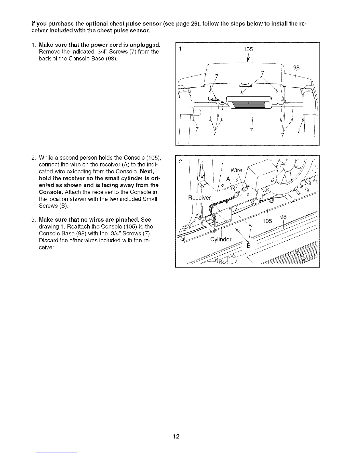
if you purchase the optional chest pulse sensor (see page 26), follow the steps below to install the re-
ceiver included with the chest pulse sensor.
1. Make sure that the power cord is unplugged.
Remove the indicated 3/4" Screws (7) from the
back of the Console Base (98).
2. While a second person holds the Console (105),
connect the wire on the receiver (A) to the indi-
cated wire extending from the Console. Next,
hold the receiver so the small cylinder is ori-
ented as shown and is facing away from the
Console. Attach the receiver to the Console in
the location shown with the two included Small
Screws (B).
1
105
98
7
7
Wire
3. Make sure that no wires are pinched. See
drawing 1. Reattach the Console (105) to the
Console Base (98) with the 3/4" Screws (7).
Discard the other wires included with the re-
ceiver.
der
12
 Loading...