

Page 1
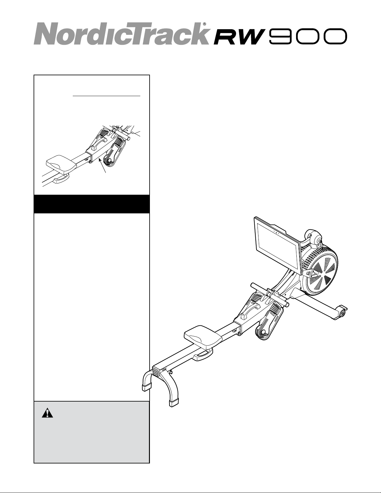
Model No. NTEVRW15920.0
Serial No.
Write the serial number in the space
above for reference.
Serial Number Decal
(under frame)
CUSTOMER SERVICE
UNITED KINGDOM
Call: 0330 123 1045
From Ireland: 053 92 36102
Website: iconsupport.eu
E-mail: csuk@iconeurope.com
Write:
ICON Health & Fitness, Ltd.
Unit 4, Westgate Court
Silkwood Park
OSSETT
WF5 9TT
UNITED KINGDOM
USER’S MANUAL
AUSTRALIA
Call: 1800 993 770
E-mail: australiacc@iconfitness.com
Write:
ICON Health & Fitness
PO Box 635
WINSTON HILLS NSW 2153
AUSTRALIA
CAUTION
Read all precautions and
instructions in this manual before
using this equipment. Keep this
manual for future reference.
iconeurope.com
Page 2
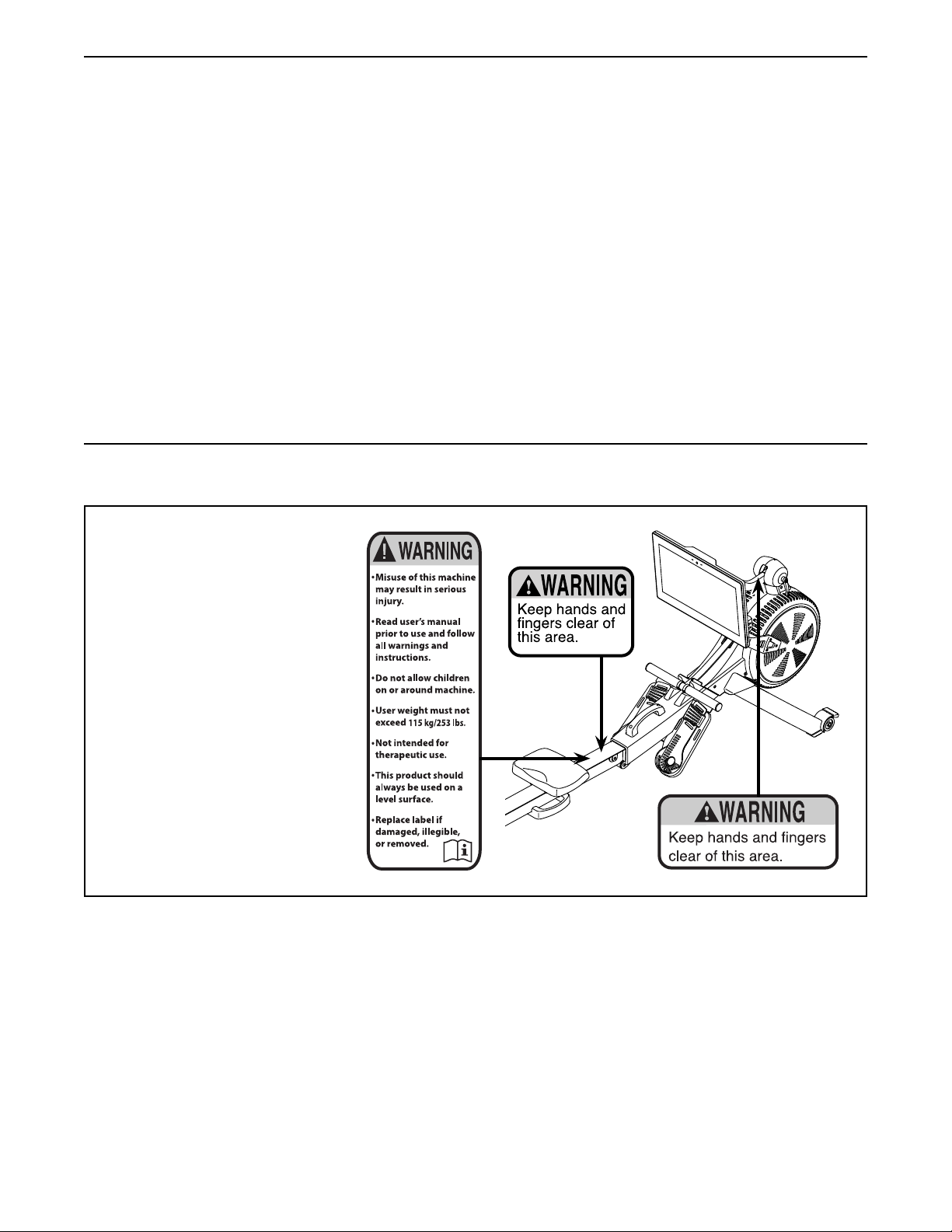
TABLE OF CONTENTS
WARNING DECAL PLACEMENT . . . . . . . . . . . . . . . . . . . . . . . . . . . . . . . . . . . . . . . . . . . . . . . . . . . . . . . . . . . . . . .2
IMPORTANT PRECAUTIONS ..................................................................3
BEFORE YOU BEGIN. . . . . . . . . . . . . . . . . . . . . . . . . . . . . . . . . . . . . . . . . . . . . . . . . . . . . . . . . . . . . . . . . . . . . . . .4
PART IDENTIFICATION CHART. . . . . . . . . . . . . . . . . . . . . . . . . . . . . . . . . . . . . . . . . . . . . . . . . . . . . . . . . . . . . . . . 5
ASSEMBLY . . . . . . . . . . . . . . . . . . . . . . . . . . . . . . . . . . . . . . . . . . . . . . . . . . . . . . . . . . . . . . . . . . . . . . . . . . . . . . . .6
HOW TO USE THE ROWER. . . . . . . . . . . . . . . . . . . . . . . . . . . . . . . . . . . . . . . . . . . . . . . . . . . . . . . . . . . . . . . . . .10
HOW TO USE THE CONSOLE. . . . . . . . . . . . . . . . . . . . . . . . . . . . . . . . . . . . . . . . . . . . . . . . . . . . . . . . . . . . . . . .13
MAINTENANCE AND TROUBLESHOOTING .....................................................23
EXERCISE GUIDELINES ....................................................................25
PART LIST. . . . . . . . . . . . . . . . . . . . . . . . . . . . . . . . . . . . . . . . . . . . . . . . . . . . . . . . . . . . . . . . . . . . . . . . . . . . . . . . 28
EXPLODED DRAWING. . . . . . . . . . . . . . . . . . . . . . . . . . . . . . . . . . . . . . . . . . . . . . . . . . . . . . . . . . . . . . . . . . . . . .30
ORDERING REPLACEMENT PARTS .................................................. Back Cover
RECYCLING INFORMATION ......................................................... Back Cover
WARNING DECAL PLACEMENT
This drawing shows the
location(s) of the warning
decal(s). If a decal is miss-
ing or illegible, see the front
cover of this manual and
request a free replacement
decal. Apply the decal in the
location shown. Note: The
decal(s) may not be shown at
actual size.
NORDICTRACK and IFIT are registered trademarks of ICON Health & Fitness, Inc. The Bluetooth® word mark
and logos are registered trademarks of Bluetooth SIG, Inc. and are used under license. Google Maps is a trademark of Google LLC. Wi-Fi is a registered trademark of Wi-Fi Alliance. WPA and WPA2 are trademarks of Wi-Fi
Alliance.
2
Page 3

IMPORTANT PRECAUTIONS
WARNING: To reduce the risk of serious injury, read all important precautions and
instructions in this manual and all warnings on the rower before using the rower. ICON assumes
no responsibility for personal injury or property damage sustained by or through the use of this
product.
1. It is the responsibility of the owner to ensure
that all users of the rower are adequately
informed of all precautions.
2. Before beginning any exercise program,
consult your physician. This is especially
important for persons over age 35 or persons with pre-existing health problems.
3. The rower is not intended for use by persons
with reduced physical, sensory, or mental
capabilities or lack of experience and knowledge, unless they are given supervision or
instruction about use of the rower by someone responsible for their safety.
4. Use the rower only as described in this
manual.
5. The rower is intended for home use only. Do
not use the rower in a commercial, rental, or
institutional setting.
6. Keep the rower indoors, away from moisture
and dust. Do not put the rower in a garage or
covered patio or near water.
7. Place the rower on a level surface, with a mat
beneath it to protect the floor or carpet. Make
sure that there is at least 2 ft. (0.6 m) of
clearance around the rower.
8. Inspect and properly tighten all parts each
time the rower is used. Replace any worn
parts immediately.
9. Keep children under age 16 and pets away
from the rower at all times.
10. Wear appropriate clothes while exercising;
do not wear loose clothes that could become
caught on the rower. Always wear athletic
shoes for foot protection.
11. The rower should not be used by persons
weighing more than 253 lbs. (115 kg).
12. Always keep your back straight while using
the rower; do not arch your back.
13. Do not release the row bar while the strap is
extended.
14. Over exercising may result in serious injury
or death. If you feel faint, if you become short
of breath, or if you experience pain while
exercising, stop immediately and cool down.
3
Page 4
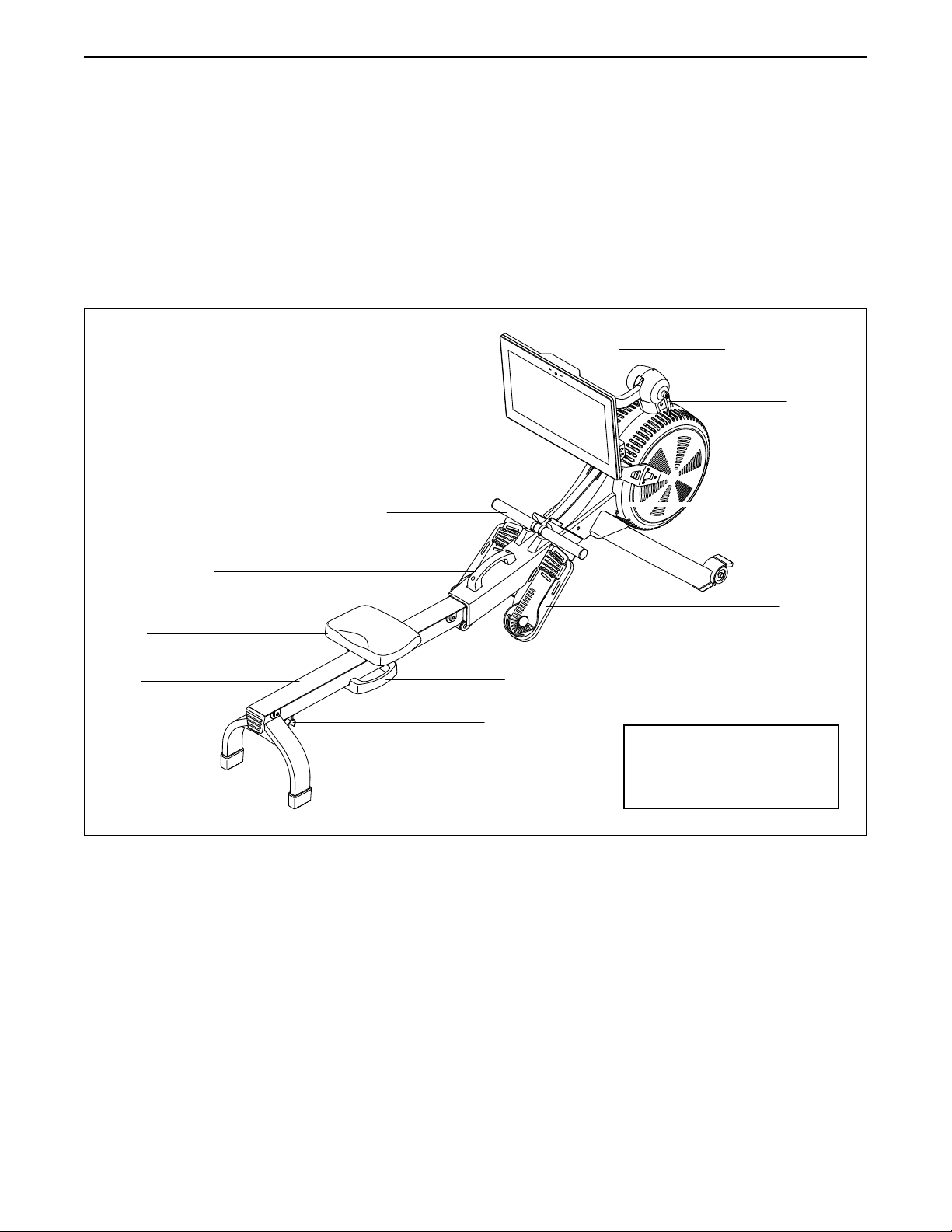
BEFORE YOU BEGIN
Thank you for selecting the new NORDICTRACK®
RW 900 rower. Rowing is an effective exercise for
increasing cardiovascular fitness, building endurance,
and toning the body. The RW 900 rower is designed to
let you enjoy this effective exercise in the convenience
and privacy of your home.
For your benefit, read this manual carefully before
you use the rower. If you have questions after reading
Console
Strap
Row Bar
Frame Handle
this manual, please see the front cover of this manual.
To help us assist you, note the product model number
and serial number before contacting us. The model
number and the location of the serial number decal are
shown on the front cover of this manual.
Before reading further, please review the drawing
below and familiarize yourself with the labeled parts.
Adjustable Neck
Handle
Resistance
Handle
Wheel
Seat
Rail
Footrest
Rail Handle
Folding Clamp
Length: 7 ft. 3 in. (221 cm)
Width: 1 ft. 10 in. (56 cm)
Weight: 108 lbs. (49 kg)
4
Page 5
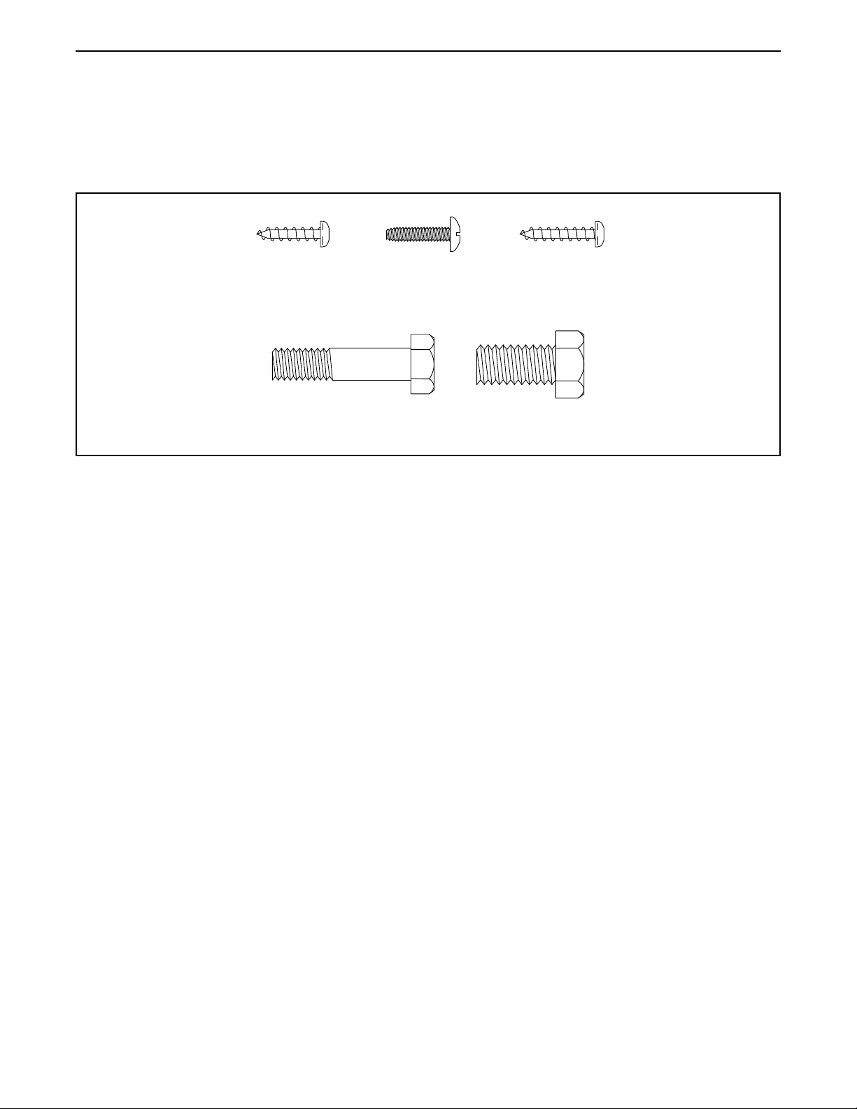
PART IDENTIFICATION CHART
Use the drawings below to identify the small parts needed for assembly. The number in parentheses below each
drawing is the key number of the part, from the PART LIST near the end of this manual. The number following the
key number is the quantity needed for assembly. Note: If a part is not in the hardware kit, check to see if it
has been preassembled. Extra parts may be included.
M4 x 16mm
Screw (68)–2
M8 x 35mm
Screw (82)–4
M4 x 16mm
Machine
Screw (93)–4
M4 x 19mm
Screw (69)–4
M10 x 20mm
Screw (61)–2
5
Page 6
ASSEMBLY
• Assembly requires two persons.
• Place all parts in a cleared area and remove the
packing materials. Do not dispose of the packing
materials until you nish all assembly steps.
• To identify small parts, see page 5.
1. To register your product and activate your
warranty in the UK, go to iconsupport.eu. If
you do not have internet access, call Customer
Service (see the front cover of this manual).
To register your product and activate your
warranty in Australia, email or post the
following information to the email address or
postal address on the front cover of this manual.
• your receipt (make sure to keep a copy)
• your name, address, and telephone number
• the model number, serial number, and name
of your product (see the front cover of this
manual)
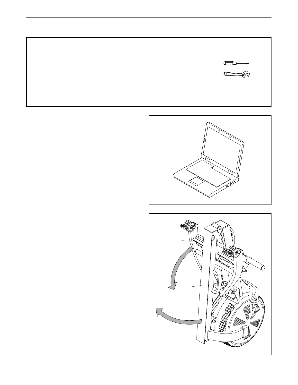
• In addition to the included tool(s), assembly
requires the following tool(s):
one Phillips screwdriver
one adjustable wrench
Assembly may be easier if you have a set of
wrenches. To avoid damaging parts, do not use
power tools.
1
2. If there are shipping tubes (not shown) attached
to the rower, remove and discard the shipping
tubes and the hardware attaching them.
With the help of a second person, pull the
Rail (2) outward and rotate the Stabilizer (3)
downward.
2
3
2
6
Page 7

3. Have a second person hold the Rail (2)
during this step.
Attach the Stabilizer (3) to the Frame (1) with
two M10 x 20mm Screws (61).
Then, hold the Rail Handle (34), pull the Rail (2)
outward, and rest the Rail on the floor (see the
drawing in step 4).
3
4. Orient the Seat (23) as shown, and slide the
Seat Carriage (5) onto the Rail (2).
2
1
3
34
61
4
2
23
5
7
Page 8
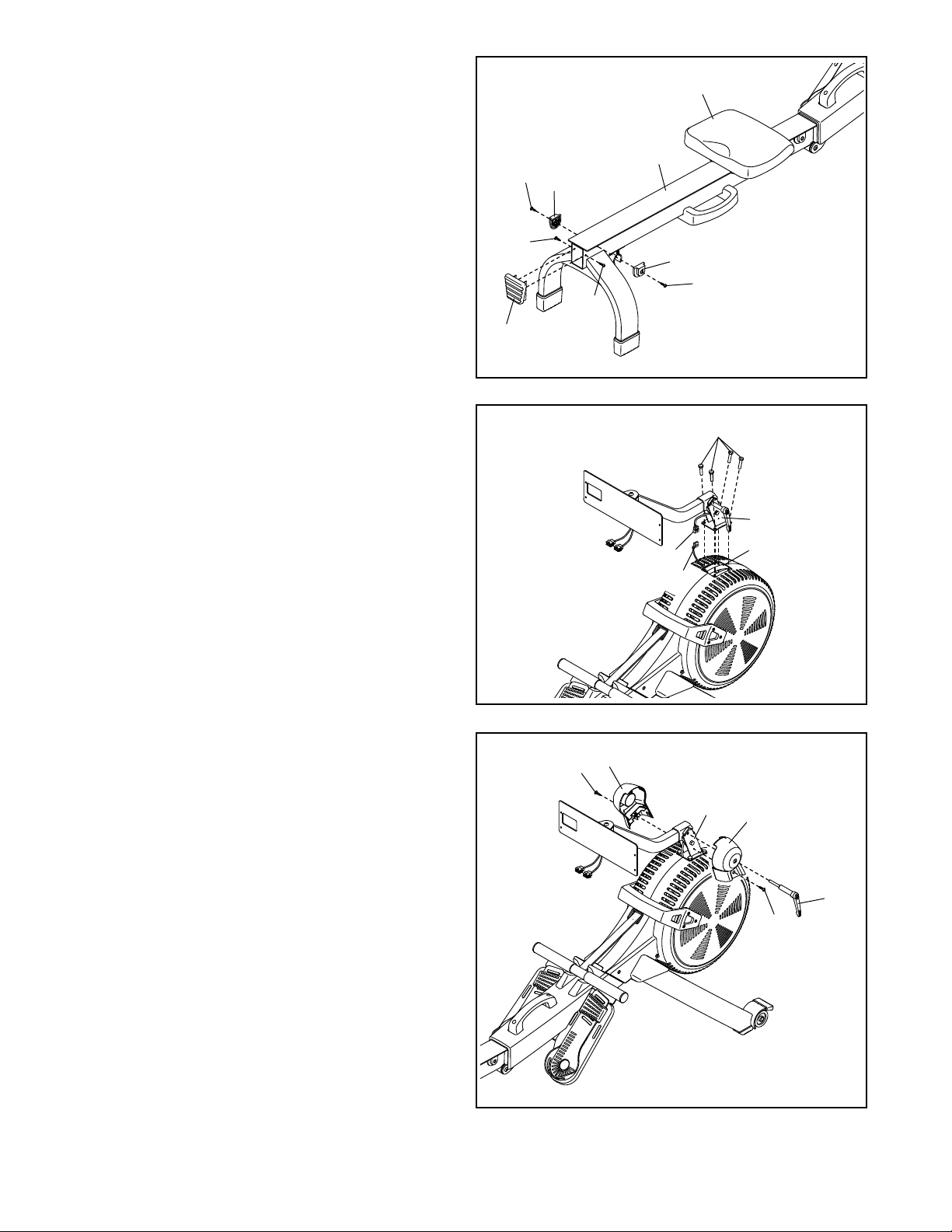
5. Slide the Seat (23) to the front of the Rail (2).
Next, attach a Stop (32) to each side of the Rail
(2) with an M4 x 19mm Screw (69).
5
23
Then, attach the Rail Cap (38) to the Rail (2)
with two M4 x 19mm Screws (69).
6. While a second person holds the Upright (77)
assembly near the Frame (1), connect the Neck
Wire (112) to the Main Wire (84).
Tip: Avoid pinching the wires. Attach
the Upright (77) to the Frame (1) with four
M8 x 35mm Screws (82); start all the Screws,
and then tighten them.
2
69
32
69
32
69
69
38
6
112
Avoid
pinching
the wires
82
77
1
84
7. Loosen and remove the Handle (78) from the
Upright (77). Note: The Handle functions like a
ratchet. Turn the Handle in the desired direction,
pull it outward, turn it in the opposite direction,
push it inward, and then turn it in the desired
direction again. Repeat this process as many
times as necessary.
Next, identify the Right and Left Upright Covers
(80, 81), and orient them as shown.
Tip: Avoid pinching the wires. Press the Right
and Left Upright Covers (80, 81) together around
the Upright (77), and attach them to the Upright
with two M4 x 16mm Screws (68).
Then, insert the Handle (78) into the Right
Upright Cover (80) and tighten it into the
Upright (77).
7
68
81
Avoid pinching
the wires
77
80
68
78
8
Page 9
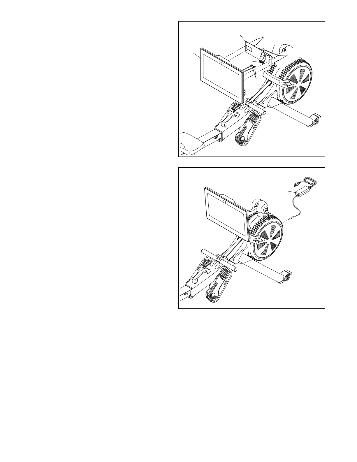
8. While a second person holds the Console (75)
near the Console Bracket (108), connect the
wires (A) on the Console to the Neck Wires (112)
in the Neck (76).
Insert the excess wires into the Neck (76) one
at a time; insert each wire as far as possible into
the Neck. Tip: Insert the wire with the larger
connector into the Neck first.
Tip: Avoid pinching the wires. If necessary,
tilt the Neck (76) upward to make this step
easier. Attach the Console (75) to the Console
Bracket (108) with four M4 x 16mm Machine
Screws (93); start all the Machine Screws, and
then tighten them.
8
75
pinching
the wires
Avoid
108
93
76
93
112
A
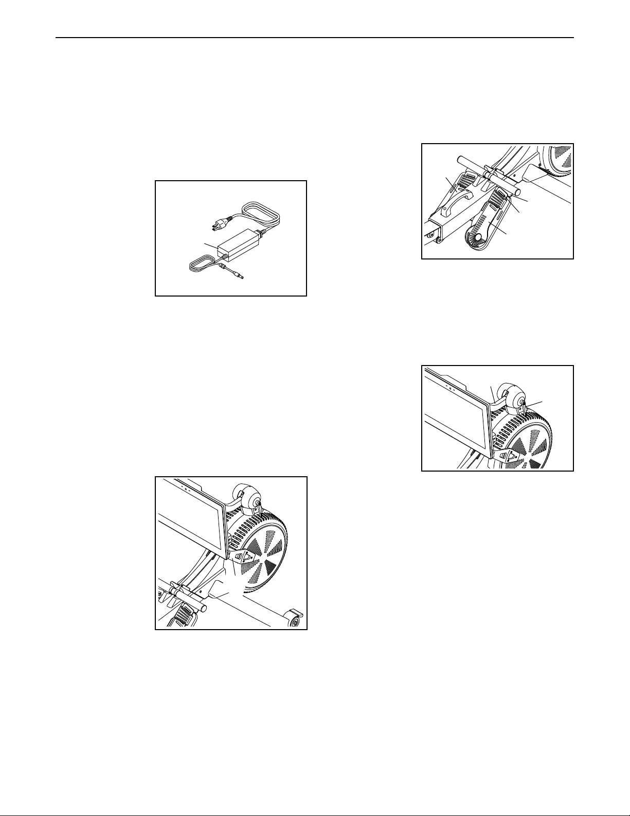
9. Plug the Power Adapter (107) into the receptacle
on the frame of the rower.
Note: To plug the Power Adapter (107) into an
outlet, see HOW TO PLUG IN THE POWER
ADAPTER on page 10.
10. Make sure that all parts are properly tightened before you use the rower. Extra parts may be included.
Place a mat under the rower to protect the floor.
9
107
9
Page 10
HOW TO USE THE ROWER
HOW TO PLUG IN THE POWER ADAPTER
IMPORTANT: If the rower has been exposed to cold
temperatures, allow it to warm to room temperature
before you plug in the power adapter (A). If you do
not do this, you may damage the console displays
or other electronic components.
Plug the power
adapter (A) into
the receptacle on
the frame of the
rower. Insert the
appropriate plug
adapter into the
power adapter if
necessary. Then,
plug the power
adapter into an
appropriate outlet that is properly installed in accordance with all local codes and ordinances.
HOW TO ADJUST THE RESISTANCE
To vary the intensity of your exercise, you can adjust
the resistance that you feel when you pull the row bar.
You can adjust the resistance both digitally and manually. First, adjust the resistance digitally, by touching
the resistance adjustment buttons on the screen (see
step 3 on page 15).
Then, fine-tune
the resistance
manually, by
moving the
resistance handle
(B). To increase
the resistance,
push the resistance handle
toward the front
of the rower; to
decrease the
resistance, pull
the resistance
handle toward the rear of the rower.
A
B
HOW TO ADJUST THE FOOT PADS
First, sit on the seat and place your feet in the foot
pads (C).
Next, press the
footrest bracket
(D), slide the foot
pad (C) to the
desired position, and then
release the footrest bracket so
that the tab (E)
engages a slot
in the foot pad.
Then, tighten the strap over your foot.
Adjust the other foot pad (C) in the same way. Make
sure that both foot pads are in the same position.
HOW TO ADJUST THE CONSOLE VIEWING ANGLE
To adjust the
console to the
desired viewing
angle, loosen
the handle (F),
raise or lower the
neck (G) to the
desired angle,
and then tighten
the handle; do
not hold or pull on the console.
Note: The handle (F) functions like a ratchet. Turn the
handle in the desired direction, pull it outward, turn it in
the opposite direction, push it inward, and then turn it
in the desired direction again. Repeat this process as
many times as necessary.
C
D
E
C
G
F
10
Page 11

HOW TO FOLD AND STORE THE ROWER
The rower can be stored in a folded position to conserve space. Store the rower in a location where
children cannot tip it. Unplug the power adapter
when you store the rower.
To store the rower, first slide the seat (H) to the rear of
the rail (I).
L, M
J
H
P
I
N
Then, pull the rail handle (K) inward until the folding
clamp (O) engages the bar on the stabilizer (P).
J
I
K
O
P
Q
K
Next, hold and lift the frame handle (J) and the rail
handle (K), and tip the rower forward onto the shields
(L, M) and the storage feet (N) (see the drawing at the
right).
Q
To unfold the rower, first place your foot on a stabilizer
foot (Q) and pull the rail handle (K) outward to disengage the folding clamp (O).
Then, hold the rail handle (K) and the frame handle (J),
pull the rail handle outward, and lower the rail (I) to the
floor.
11
Page 12

HOW TO MOVE THE ROWER IN THE UNFOLDED
POSITION
Stand behind the
rower and lift the
rail (I) until the
rower will roll on
the wheels. Then,
carefully move
the rower to the
desired location,
and lower the rail
to the floor. Do
not hold or pull
on the console
when moving the rower.
HOW TO MOVE THE ROWER IN THE FOLDED
POSITION
See HOW TO FOLD AND STORE THE ROWER on
page 11, and fold the rower. Then, hold the frame
handle (J), place your foot on a stabilizer foot (Q), and
tip the rower until it will roll on the wheels. Carefully
move the rower to the desired location, and then tip it
into the storage position. Do not hold or pull on the
console when moving the rower.
I
HOW TO ROW ON THE ROWER
Sit on the seat, place your feet in the footrests, and
adjust the straps to fit your feet. Then, hold the row bar
with an overhand grip.
Correct rowing form consists of three phases:
1. The first phase is the CATCH. Slide the seat
forward until your knees are almost touching your
chest. Pull the row bar until your hands are directly
above your feet.
2. The second phase is the DRIVE. Push backward
with your legs. Lean back slightly at the hips (not
at the waist), keeping your back straight. As you
straighten your legs, pull the row bar toward your
chest. Keep your elbows outward.
3. The third phase is the FINISH. Your legs should
be nearly straight. Continue to pull the row bar until
your hands are even with your chest.
After the finish phase, extend your arms forward and
pull the seat forward using your legs. Repeat this
sequence, moving through all three phases with a
smooth, fluid motion. Remember to breathe normally
as you row; never hold your breath.
J
Q
12
Page 13

HOW TO USE THE CONSOLE
FEATURES OF THE CONSOLE
The advanced console offers an array of features
designed to make your workouts more effective and
enjoyable.
The console features wireless technology that enables
the console to connect to iFit. With iFit, you can access
a large and varied workout library, create your own
workouts, track your workout results, and access many
other features.
In addition, the console features a selection of onboard
workouts. Each workout automatically controls the
resistance of the row bar as it guides you through an
effective exercise session.
When you use the manual mode of the console, you
can change the resistance of the row bar with the
touch of a button.
While you exercise, the console will display continuous
exercise feedback. You can also measure your heart
rate using an optional chest heart rate monitor (see
page 22 for more information).
You can also listen to your favorite workout music or
audio books with the console sound system while you
exercise.
To activate the console or turn off the console,
see page 14. To learn how to use the touch
screen, see page 14. To set up the console, see
page 15.
13
Page 14

HOW TO ACTIVATE THE CONSOLE
HOW TO USE THE TOUCH SCREEN
The included power adapter must be used to operate
the rower. See HOW TO PLUG IN THE POWER
ADAPTER on page 10. When the power adapter
is plugged in, simply touch the screen to activate the
console.
HOW TO TURN OFF THE CONSOLE
When you are finished exercising, unplug the power
adapter. IMPORTANT: If you do not do this, the
electrical components on the rower may wear
prematurely.
The console features a tablet with a full-color touch
screen. The following information will help you use the
touch screen:
• The console functions similarly to other tablets. You
can slide or flick your finger against the screen to
move certain images on the screen, such as the
displays in a workout.
• To type information into a text box, first touch the text
box to view the keyboard. To use numbers or other
characters on the keyboard, touch ?123. To view
more characters, touch ~[<. Touch ?123 again to
return to the number keyboard. To return to the letter
keyboard, touch ABC. To use a capital character,
touch the shift button (upward-facing arrow symbol).
To use multiple capital characters, touch the shift
button again. To return to the lowercase keyboard,
touch the shift button a third time. To clear the last
character, touch the clear button (backward-facing
arrow with an X symbol).
14
Page 15

HOW TO SET UP THE CONSOLE
Before you use the rower for the first time, set up the
console.
1. Connect to your wireless network.
To use iFit workouts and to use several other
features of the console, the console must be
connected to a wireless network. Follow the
prompts on the screen to connect the console to
your wireless network.
2. Customize settings.
The console is now ready for you to begin working out.
The following pages explain the workouts and other
features that the console offers.
To use the manual mode, see this page. To use
a featured workout or an onboard workout, see
page 16. To create a draw-your-own-map workout, see page 18. To use an iFit workout, see
page 19.
To change console settings, see page 20. To
connect to a wireless network, see page 21. To
use the sound system, see page 21. To connect
an HDMI cable, see page 22.
Follow the prompts on the screen to set your time
zone and other settings.
Note: To change these settings later, see HOW TO
CHANGE CONSOLE SETTINGS on page 20.
3. Log into or create an iFit account.
Follow the prompts on the screen to log into your
iFit account or to create an iFit account.
4. Tour the console.
The first time you use the console, a tour
presentation will guide you through the features of
the console.
5. Check for firmware updates.
First, touch the menu button (three horizontal lines
symbol), touch Settings, touch Maintenance, and
then touch Update. The console will check for firmware updates. For more information, see HOW TO
CHANGE CONSOLE SETTINGS on page 20.
Note: If there is a sheet of plastic on the screen,
remove the plastic.
HOW TO USE THE MANUAL MODE
1. Touch the screen to turn on the console.
See HOW TO ACTIVATE THE CONSOLE on
page 14. Note: It may take a few moments for
the console to be ready for use.
2. Select the main menu.
When you activate the console, the main menu will
appear on the screen after the console boots up.
If you are in a workout, touch the screen and follow
the prompts to end the workout and return to the
main menu. If you are in the settings menus, touch
the back button (arrow symbol) and then touch the
close button (x symbol) to return to the main menu.
3. Adjust the resistance to the desired level.
Touch Manual Start and begin rowing.
You can adjust the resistance that you feel when
you pull the row bar both digitally and manually.
15
Page 16

First, adjust the resistance digitally by pressing
the resistance adjustment buttons on the screen.
The selected resistance level will appear on the
screen.
Note: After you touch a button, it will take a
moment for the rower to reach the selected
resistance level.
5. Wear a heart rate monitor and measure your
heart rate if desired.
You can wear an optional heart rate monitor
to measure your heart rate. For more information about the optional heart rate monitor, see
page 22. Note: The console is compatible with
Bluetooth® Smart heart rate monitors.
Then, fine-tune the resistance adjustment
manually if desired by moving the resistance
handle (see HOW TO ADJUST THE RESISTANCE
on page 10).
4. Follow your progress.
The console offers several display modes. The
display mode that you select will determine which
workout information is shown.
Drag upward on the screen to enter the fullscreen
display mode. Drag downward on the screen to
view the workout information displays.
Touch the various workout information displays
to view more options. Touch the more button
(+ symbol) to view statistics or charts. Touch the
center of the screen to view even more display
mode options.
If desired, adjust the volume level by pressing the
volume increase and decrease buttons on the right
side of the console.
To pause the workout, simply touch the screen
or stop rowing. To continue the workout, simply
resume rowing.
To end the workout session, touch the screen to
pause the workout, and then follow the prompts
on the screen to end the workout and return to the
main menu.
When your heartbeat is detected, your heart rate
will be shown on the screen.
6. When you are finished exercising, unplug the
power adapter.
See HOW TO TURN OFF THE CONSOLE on
page 14.
HOW TO USE A FEATURED WORKOUT OR AN
ONBOARD WORKOUT
1. Touch the screen to turn on the console.
See HOW TO ACTIVATE THE CONSOLE on
page 14. Note: It may take a few moments for
the console to be ready for use.
2. Select the main menu or the workout library.
When you turn on the console, the main menu will
appear on the screen after the console boots up.
If you are in a workout, touch the screen and follow
the prompts to end the workout and return to the
main menu. If you are in the settings menus, touch
the back button (arrow symbol) and then touch the
close button (x symbol) to return to the main menu.
Touch the buttons at the bottom of the screen to
select either the main menu (Home button) or the
workout library (Browse button).
16
Page 17

3. Select a workout.
To select a workout from the main menu or the
workout library, simply touch the desired workout
button on the screen. Slide or flick the screen to
scroll upward or downward if necessary.
Note: To use a featured workout, the console must
be connected to a wireless network (see HOW
TO CONNECT TO A WIRELESS NETWORK on
page 21).
The featured workouts on your console will change
periodically. To save one of the featured workouts
for future use, you can add it as a favorite by touching the favorites button (heart symbol). You must
be logged into your iFit account to save a featured
workout (see step 3 on page 19).
To draw your own map for a workout, see HOW TO
CREATE A DRAW-YOUR-OWN-MAP WORKOUT
on page 18.
When you select a workout, the screen will show
an overview of the workout that includes details
such as the duration and distance of the workout
and the approximate number of calories you will
burn during the workout.
4. Start the workout.
Touch Start Workout to start the workout.
During some workouts, an iFit coach will guide you
through a video workout. Touch the sound button
(music notes symbol) to select music, trainer voice,
and volume options for the workout.
During the workout, the resistance of the row bar
will automatically increase or decrease. If the resistance level is too high or too low, you can manually
override the setting by touching the resistance
adjustment buttons on the screen. If you press
a resistance adjustment button, you can then
manually control the resistance level (see step 3
on page 15). To return to the programmed
resistance settings of the workout, touch Follow
Workout.
Note: The calorie goal shown in the workout
description is an estimate of the number of
calories that you will burn during the workout.
The actual number of calories that you burn
will depend on various factors, such as your
weight. In addition, if you manually change the
resistance level during the workout, the number
of calories you burn will be affected.
To pause the workout, simply touch the screen
or stop rowing. To continue the workout, simply
resume rowing.
To end the workout, touch the screen to pause the
workout, and then follow the prompts on the screen
to end the workout and return to the main menu.
When the workout ends, a workout summary will
appear on the screen. If desired, you can select
options such as adding the workout to your schedule (see HOW TO USE AN IFIT WORKOUT on
page 19) or adding the workout to your favorites
list. Then, touch Save Workout to return to the main
menu.
5. Follow your progress.
During some workouts, the screen will show a map
of the route and a marker indicating your progress. Touch the buttons on the screen to select the
desired map options.
During some workouts, the screen may show a
target rate. As you exercise, keep your rowing
rate near the target rate shown on the screen. A
message may appear prompting you to increase,
decrease, or maintain your rowing rate.
IMPORTANT: The target rate is intended only to
provide motivation. Your actual rowing rate may
be slower than the target rate. Make sure to row
at a lane that is comfortable for you.
See step 4 on page 16.
6. Wear a heart rate monitor and measure your
heart rate if desired.
See step 5 on page 16.
7. When you are finished exercising, unplug the
power adapter.
See HOW TO TURN OFF THE CONSOLE on
page 14.
17
Page 18

HOW TO CREATE A DRAW-YOUR-OWN-MAP
WORKOUT
If you make a mistake, touch Undo in the map
options.
1. Touch the screen to turn on the console.
See HOW TO ACTIVATE THE CONSOLE on
page 14. Note: It may take a few moments for
the console to be ready for use.
2. Select a draw-your-own-map workout.
When you turn on the console, the main menu will
appear on the screen after the console boots up.
If you are in a workout, touch the screen and follow
the prompts to end the workout and return to the
main menu. If you are in the settings menus, touch
the back button (arrow symbol) and then touch the
close button (x symbol) to return to the main menu.
To select a draw-your-own-map workout, touch the
Create button at the bottom of the screen.
3. Draw your map.
Navigate to the area on the map where you want
to draw your workout by sliding your fingers on the
screen. Touch the screen to add the start point for
your workout. Then, touch the screen to add the
end point for your workout.
If you want to start and end your workout at the
same point, touch Close Loop or Out & Back in the
map options. You can also select whether you want
your workout to snap to the road.
The screen will display the elevation and distance
statistics for your workout.
4. Save your workout.
Touch Save New Workout to save your workout. If
desired, enter a title and description for your workout. Then, touch the continue button (> symbol).
5. Start the workout.
Touch Start Workout to start the workout. The
workout will function in the same way as a featured
workout or an onboard workout (see page 16).
6. Follow your progress.
See step 4 on page 16.
7. Wear a heart rate monitor and measure your
heart rate if desired.
See step 5 on page 16.
8. When you are finished exercising, unplug the
power adapter.
See HOW TO TURN OFF THE CONSOLE on
page 14.
18
Page 19

HOW TO USE AN IFIT WORKOUT
To use an iFit workout, the console must be connected
to a wireless network (see HOW TO CONNECT TO A
WIRELESS NETWORK on page 21). An iFit account
is also required.
1. Add workouts to your schedule on iFit.com.
To switch users within your iFit account, touch
the menu button, touch Settings, and then touch
Manage Accounts. If more than one user is associated with the account, a list of users will appear.
Touch the name of the desired user.
4. Select an iFit workout that you have previously
added to your schedule on iFit.com.
On your computer, smartphone, tablet, or other
device, open an internet browser, go to iFit.com,
and log in to your iFit account.
Next, navigate to Menu > Library on the website.
Browse the workout programs in the library and join
the desired workouts.
Then, navigate to Menu > Schedule to view your
schedule. All of the workouts that you have joined
will appear on your schedule; you can arrange or
delete the workouts on your schedule as desired.
Take time to explore the iFit.com website before
you log out.
2. Select the main menu.
When you turn on the console, the main menu will
appear on the screen after the console boots up.
If you are in a workout, touch the screen and follow
the prompts to end the workout and return to the
main menu. If you are in the settings menus, touch
the back button (arrow symbol) and then touch the
close button (x symbol) to return to the main menu.
IMPORTANT: Before iFit workouts will load, you
must add them to your schedule on iFit.com
(see step 1).
To load an iFit workout from iFit.com to the
console, touch the Calendar button at the bottom of
the screen.
When you load a workout, the screen will show an
overview of the workout that includes details such
as the duration and distance of the workout and
the approximate number of calories you will burn
during the workout.
5. Start the workout.
Touch Start Workout to start the workout. The
workout will function in the same way as a featured
workout or an onboard workout (see page 16).
6. Follow your progress.
See step 4 on page 16.
7. Wear a heart rate monitor and measure your
heart rate if desired.
3. Log in to your iFit account.
If you have not already done so, touch the menu
button (three horizontal lines symbol) on the screen
and then touch Log in to log in to your iFit account.
Follow the prompts on the screen to enter your
username and password.
See step 5 on page 16.
8. When you are finished exercising, unplug the
power adapter.
See HOW TO TURN OFF THE CONSOLE on
page 14.
For more information about iFit, go to iFit.com.
19
Page 20

HOW TO CHANGE CONSOLE SETTINGS
3. Customize settings.
IMPORTANT: Some of the settings and features
described may not be enabled. Occasionally, a
firmware update may cause your console to function
slightly differently.
1. Select the settings main menu.
First, activate the console (see HOW TO
ACTIVATE THE CONSOLE on page 14). Note:
It may take a few moments for the console to be
ready for use.
Next, select the main menu (Home button). When
you turn on the console, the main menu will appear
on the screen after the console boots up. If you
are in a workout, touch the screen and follow the
prompts to end the workout and return to the main
menu. If you are in the settings menus, touch the
back button (arrow symbol) and then touch the
close button (x symbol) to return to the main menu.
Then, touch the menu button (three horizontal lines
symbol) on the screen, and then touch Settings.
The settings menu will appear on the screen.
2. Navigate the settings menus and change
settings as desired.
Slide or flick the screen to scroll upward or down-
ward if necessary. To view a settings menu, simply
touch the menu name. To exit a menu, touch the
back button (arrow symbol). You may be able to
view and change settings in the following settings
menus:
Account
• My Prole
• In Workout
• Manage Accounts
To customize the time zone or other settings, touch
Equipment Info or Equipment Settings, and then
touch the desired settings.
4. View machine information.
Touch Equipment Info, and then touch Machine
Info to view information about your rower or about
the console app.
5. Update the console firmware.
For the best results, regularly check for
firmware updates. Touch Maintenance, and then
touch Update to check for firmware updates using
your wireless network. The update will begin automatically. IMPORTANT: To avoid damaging the
rower, do not unplug the power adapter while
the firmware is being updated.
The screen will show the progress of the update.
When the update is complete, the rower will turn
off and then turn back on. If it does not, unplug and
then plug in the power adapter. Note: It may take a
few minutes for the console to be ready for use.
Note: Occasionally, a firmware update may cause
the console to function slightly differently. These
updates are always designed to improve your
exercise experience.
6. Exit the settings main menu.
If you are in a settings menu, touch the back
button. Then, touch the close button (x symbol) to
exit the settings main menu.
Equipment
• Equipment Info
• Equipment Settings
• Maintenance
• Wi-Fi
About
• Legal
20
Page 21

HOW TO CONNECT TO A WIRELESS NETWORK
To use iFit workouts and to use several other features
of the console, the console must be connected to a
wireless network.
1. Select the main menu.
When the console is connected to your wireless
network, a checkmark will appear next to the
wireless network name.
If you are having problems connecting to an
encrypted network, make sure that your password
is correct. Note: Passwords are case-sensitive.
First, turn on the power (see HOW TO ACTIVATE
THE CONSOLE on page 14). Note: It may take
a few moments for the console to be ready for use.
Next, select the main menu (Home button). When
you turn on the console, the main menu will appear
on the screen after the console boots up. If you
are in a workout, touch the screen and follow the
prompts to end the workout and return to the main
menu. If you are in the settings menus, touch the
back button (arrow symbol) and then touch the
close button (x symbol) to return to the main menu.
2. Select the wireless network menu.
Touch the menu button (three horizontal lines
symbol, and then touch Wi-Fi to select the wireless
network menu.
3. Enable Wi-Fi.
Make sure that Wi-Fi® is enabled. If it is not
enabled, touch the Wi-Fi toggle to enable it.
4. Set up and manage a wireless network
connection.
When Wi-Fi is enabled, the screen will show a
list of available networks. Note: It may take a few
moments for the list of wireless networks to appear.
Note: The console supports unsecured and
secured (WEP, WPA™, and WPA2™) encryption.
A broadband connection is recommended; performance depends on connection speed.
Note: If you have questions after following
these instructions, go to support.iFit.com for
assistance.
5. Exit the wireless network menu.
To exit the wireless network menu, touch the back
button (arrow symbol).
HOW TO USE THE SOUND SYSTEM
To play music or audio books through the console
sound system while you exercise, plug a 3.5 mm male
to 3.5 mm male audio cable (not included) into the
jack on the right side of the console and into a jack on
your personal audio player; make sure that the audio
cable is fully plugged in. Note: To purchase an
audio cable, see your local electronics store.
Next, press the play button on your personal audio
player. Adjust the volume level by pressing the volume
increase and decrease buttons on the right side of the
console or the volume control on your personal audio
player.
Note: You must have your own wireless network
and an 802.11b/g/n router with SSID broadcast
enabled (hidden networks are not supported).
When a list of networks appears, touch the desired
network. Note: You will need to know your network
name (SSID). If your network has a password, you
will also need to know the password.
Follow the prompts on the screen to enter your
password and connect to the selected wireless
network. (To use the keyboard, see HOW TO USE
THE TOUCH SCREEN on page 14.)
To listen to the console audio with your personal
headphones or ear buds, plug your headphones into
the headphones jack on the right side of the console.
21
Page 22

HOW TO CONNECT AN HDMI CABLE
THE OPTIONAL CHEST HEART RATE MONITOR
To show your console screen on a TV or monitor, plug
an HDMI cable (not included) into the port on the console and into a port on your TV or monitor; make sure
that the HDMI cable is fully plugged in. Note: To
purchase an HDMI cable, see your local electronics
store.
Whether your
goal is to
burn fat or to
strengthen your
cardiovascular
system, the key
to achieving the
best results is
to maintain the
proper heart
rate during your
workouts. The optional chest heart rate monitor will
enable you to continuously monitor your heart rate
while you exercise, helping you to reach your personal
fitness goals. To purchase a chest heart rate moni-
tor, please see the front cover of this manual.
Note: The console is compatible with all Bluetooth
Smart heart rate monitors.
22
Page 23

MAINTENANCE AND TROUBLESHOOTING
MAINTENANCE
Regular maintenance is important for optimal
performance and to reduce wear. Inspect and properly
tighten all parts each time the rower is used. Replace
any worn parts immediately.
To clean the rower, use a damp cloth and a small
amount of mild detergent. IMPORTANT: To avoid
damage to the console, keep liquids away from
the console and keep the console out of direct
sunlight.
For the best results, clean the rail, the seat carriage,
and the carriage rollers daily.
CONSOLE TROUBLESHOOTING
If the console does not turn on, make sure that the
power adapter is fully plugged in. If there are exterior
wires on the console, make sure that the connectors
on the wires are oriented correctly and are connected
firmly to the receptacles in the console.
If you are having problems connecting the console
to a wireless network, or if you are having problems
with your iFit account or iFit workouts, go to
support.iFit.com.
If a replacement power adapter is needed, call the
telephone number on the cover of this manual.
IMPORTANT: To avoid damaging the console, use
only a manufacturer-supplied regulated power
adapter.
If the console does not boot
up properly, or if the console freezes and does not
respond, reset the console
to the factory default settings. IMPORTANT: Doing
this will erase all custom settings you have made
to the console. Resetting the console requires two
people. First, unplug the power adapter. Next, locate
the small reset opening (A) near the USB port on the
console. Using a bent paper clip, press and hold the
reset button inside the opening, and have a second
person plug in the power adapter. Continue holding the
reset button until the console turns on. When the reset
operation is complete, the console will turn off and then
turn back on. If it does not, unplug and then plug in the
power adapter. Once the console turns on, check for
rmware updates (see step 5 on page 20). Note: It may
take a few minutes for the console to be ready for use.
A
23
Page 24

HOW TO ADJUST THE REED SWITCH
If the console does not display correct feedback, the
reed switch should be adjusted. To adjust the reed
switch, first unplug the power adapter. Then, remove
the parts described below.
First, remove the
six M4 x 10mm
Screws (70) and
gently remove
the Resistance
Handle (9).
70
9
70
Next, locate the Reed Switch (47). Turn the Left Fan
(4) until a Magnet (85) is aligned with the Reed Switch.
Then, slightly loosen the two indicated M4 x 19mm
Screws (69), slide the Reed Switch slightly closer to or
away from the Magnet, and then retighten the Screws.
47
4
See EXPLODED DRAWING B on page 31. Locate
the Right and Left Shields (7, 8). Remove the four
M4 x 19mm Screws (69) and the ten M4 x 16mm
Screws (68) from the Right and Left Shields. Then,
gently remove the Right and Left Shields.
85
69
Plug in the power adapter, and then turn the Left Fan
(4) so that the Magnet (85) passes the Reed Switch
(47) repeatedly. Repeat the actions described above
until the console displays correct feedback.
When the reed switch is correctly adjusted, reattach
the parts that you removed.
24
Page 25

EXERCISE GUIDELINES
WARNING: Before beginning this
or any exercise program, consult your physician. This is especially important for persons
over age 35 or persons with pre-existing
health problems.
Aerobic Exercise—If your goal is to strengthen your
cardiovascular system, you must perform aerobic
exercise, which is activity that requires large amounts
of oxygen for prolonged periods of time. For aerobic
exercise, adjust the intensity of your exercise until
your heart rate is near the highest number in your
training zone.
These guidelines will help you to plan your exercise
program. For detailed exercise information, obtain a
reputable book or consult your physician. Remember,
proper nutrition and adequate rest are essential for
successful results.
EXERCISE INTENSITY
Whether your goal is to burn fat or to strengthen your
cardiovascular system, exercising at the proper intensity is the key to achieving results. You can use your
heart rate as a guide to find the proper intensity level.
The chart below shows recommended heart rates for
fat burning and aerobic exercise.
To find the proper intensity level, find your age at the
bottom of the chart (ages are rounded off to the nearest ten years). The three numbers listed above your
age define your “training zone.” The lowest number is
the heart rate for fat burning, the middle number is the
heart rate for maximum fat burning, and the highest
number is the heart rate for aerobic exercise.
HOW TO MEASURE YOUR HEART RATE
To measure your heart
rate, exercise for at
least four minutes.
Then, stop exercising and place two
fingers on your wrist
as shown. Take a
six-second heartbeat
count, and multiply the
result by 10 to find your heart rate. For example, if your
six-second heartbeat count is 14, your heart rate is 140
beats per minute.
WORKOUT GUIDELINES
Warming Up—Start with 5 to 10 minutes of stretch-
ing and light exercise. A warm-up increases your body
temperature, heart rate, and circulation in preparation
for exercise.
Training Zone Exercise—Exercise for 20 to 30 minutes with your heart rate in your training zone. (During
the first few weeks of your exercise program, do not
keep your heart rate in your training zone for longer
than 20 minutes.) Breathe regularly and deeply as you
exercise; never hold your breath.
Cooling Down—Finish with 5 to 10 minutes of stretching. Stretching increases the flexibility of your muscles
and helps to prevent post-exercise problems.
Burning Fat—To burn fat effectively, you must exercise at a low intensity level for a sustained period of
time. During the first few minutes of exercise, your
body uses carbohydrate calories for energy. Only
after the first few minutes of exercise does your body
begin to use stored fat calories for energy. If your
goal is to burn fat, adjust the intensity of your exercise until your heart rate is near the lowest number in
your training zone. For maximum fat burning, exercise
with your heart rate near the middle number in your
training zone.
EXERCISE FREQUENCY
To maintain or improve your condition, complete
three workouts each week, with at least one day of
rest between workouts. After a few months of regular
exercise, you may complete up to five workouts each
week, if desired. Remember, the key to success is to
make exercise a regular and enjoyable part of your
everyday life.
25
Page 26

SUGGESTED STRETCHES
The correct form for several basic stretches is shown at the right. Move slowly as you stretch; never bounce.
1. Toe Touch Stretch
Stand with your knees bent slightly and slowly bend forward from
your hips. Allow your back and shoulders to relax as you reach down
toward your toes as far as possible. Hold for 15 counts, then relax.
Repeat 3 times. Stretches: Hamstrings, back of knees and back.
2. Hamstring Stretch
Sit with one leg extended. Bring the sole of the opposite foot toward
you and rest it against the inner thigh of your extended leg. Reach
toward your toes as far as possible. Hold for 15 counts, then relax.
Repeat 3 times for each leg. Stretches: Hamstrings, lower back and
groin.
3. Calf/Achilles Stretch
With one leg in front of the other, reach forward and place your hands
against a wall. Keep your back leg straight and your back foot flat on
the floor. Bend your front leg, lean forward and move your hips toward
the wall. Hold for 15 counts, then relax. Repeat 3 times for each leg.
To cause further stretching of the achilles tendons, bend your back
leg as well. Stretches: Calves, achilles tendons and ankles.
4. Quadriceps Stretch
With one hand against a wall for balance, reach back and grasp one
foot with your other hand. Bring your heel as close to your buttocks
as possible. Hold for 15 counts, then relax. Repeat 3 times for each
leg. Stretches: Quadriceps and hip muscles.
1
2
3
4
5. Inner Thigh Stretch
Sit with the soles of your feet together and your knees outward.
Pull your feet toward your groin area as far as possible. Hold for 15
counts, then relax. Repeat 3 times. Stretches: Quadriceps and hip
muscles.
5
26
Page 27

NOTES
27
Page 28

PART LIST
Key No. Qty. Description Key No. Qty. Description
Model No. NTEVRW15920.0 R0919A
1 1 Frame
2 1 Rail
3 1 Stabilizer
4 1 Left Fan
5 1 Seat Carriage
6 2 Deflector
7 1 Right Shield
8 1 Left Shield
9 1 Resistance Handle
10 1 Strap Grommet
11 1 Bungee Cord
12 1 Row Bar/Strap
13 2 Resistance Pad
14 1 Right Neck Bushing
15 1 Left Neck Bushing
16 2 Footrest Strap
17 1 Right Footrest
18 1 Right Foot Pad
19 1 Right Footrest Bracket
20 1 Left Footrest Bracket
21 1 Left Footrest
22 1 Left Foot Pad
23 1 Seat
24 2 Bearing A
25 4 Snap Ring
26 1 Bushing
27 2 Bearing B
28 2 15mm Wave Washer
29 1 Pulley Assembly
30 1 Axle
31 2 Pivot Bushing
32 4 Stop
33 1 Bumper
34 1 Rail Handle
35 1 Folding Clamp
36 2 Rail Foot
37 2 Small Carriage Roller
38 1 Rail Cap
39 2 Large Carriage Roller
40 2 Carriage Axle
41 2 Stabilizer Foot
42 4 Wheel
43 2 Storage Foot
44 5 Rail Pulley
45 2 Strap Roller
46 2 Strap Axle
47 1 Reed Switch/Wire
48 1 Frame Pulley
49 1 Frame Foot
50 1 Clamp
51 1 Row Bar Rest
52 1 Frame Handle
53 1 Pivot Axle
54 12 Deflector Bracket
55 2 Pulley Bracket
56 6 6mm Washer
57 9 M6 Locknut
58 3 M8 Washer
59 2 M8 x 12mm Screw
60 1 M10 x 40mm Bolt
61 2 M10 x 20mm Screw
62 8 5mm Washer
63 8 M5 x 10mm Screw
64 4 #8 x 3/4" Screw
65 12 M6 x 15mm Screw
66 2 M10 Flange Nut
67 2 Clip
68 12 M4 x 16mm Screw
69 32 M4 x 19mm Screw
70 6 M4 x 10mm Screw
71 10 M8 x 12mm Screw
72 1 Right Fan
73 4 8mm Washer
74 1 One-way Bearing
75 1 Console
76 1 Neck
77 1 Upright
78 1 Handle
79 1 Wire Grommet
80 1 Right Upright Cover
81 1 Left Upright Cover
82 4 M8 x 35mm Screw
83 1 M8 x 50mm Hex Bolt
84 1 Main Wire
85 4 Magnet
86 6 M8 Locknut
87 12 M4 x 10mm Flat Head Screw
88 2 Bearing Bracket
89 1 Handle Bracket
90 1 Link Arm
91 1 Magnet Bracket
92 1 Resistance Magnet
93 4 M4 x 16mm Machine Screw
94 2 Magnet Screw
95 2 Handle Bracket Screw
96 1 M6 x 12mm Hex Screw
97 1 M8 x 12mm Hex Screw
98 1 M6 Washer
99 4 M4 x 12mm Screw
100 1 Resistance Motor
28
Page 29

Key No. Qty. Description Key No. Qty. Description
101 2 M4 Nut
102 1 Resistance Disc
103 1 M3 x 8mm Screw
104 2 Saddle
105 2 Spring
106 1 Power Receptacle/Wire
107 1 Power Adapter
108 1 Console Bracket
Note: Specications are subject to change without notice. For information about ordering replacement parts, see
the back cover of this manual. *These parts are not illustrated.
109 2 Pivot Disc
110 1 M8 x 80mm Bolt
111 1 M6 Shoulder Screw
112 1 Neck Wire
113 1 Resistance Pad Bracket
114 4 M4 x 10mm Screw
* – User’s Manual
* – Assembly Tool
29
Page 30

EXPLODED DRAWING A
Model No. NTEVRW15920.0 R0919A
78
68
83
24
29
80
113
74
24
62
57
26
63
25
88
104
71
44
105
86
114
60
13
73
42
43
27
71
66
25
84
86
73
42
41
3
61
112
82
86
56
68
94
15
82
50
69
48
64
47
81
86
14
49
77
1
76
93
109
110
93
108
79
75
109
111
57
92
91
107
72
106
69
66
85
97
58
101
96
4
27
98
102
103
71
90
99
89
101
25
69
71
88
100
25
28
57
30
63
51
62
17
13
46
19
52
30
45
105
57
104
56
65
44
55
20
57
18
21
65
22
59
44
58
53
16
69
57
56
59
58
44
55
44
56
57
Page 31

EXPLODED DRAWING B
Model No. NTEVRW15920.0 R0919A
70
95
54
95
31
68
33
6
11
69
34
68
54
68
68
69
54
87
7
10
54
87
32
32
54
70
9
54
87
87
54
87
54
68
68
69
31
2
8
69
12
6
23
69
32
67
5
40
62
63
69
69
39
35
36
38
69
65
63
62
57
56
37
65
31
Page 32

ORDERING REPLACEMENT PARTS
To order replacement parts, please see the front cover of this manual. To help us assist you, be prepared to
provide the following information when contacting us:
• the model number and serial number of the product (see the front cover of this manual)
• the name of the product (see the front cover of this manual)
• the key number and description of the replacement part(s) (see the PART LIST and the EXPLODED DRAWING
near the end of this manual)
RECYCLING INFORMATION
This electronic product must not be disposed of in municipal waste. To
preserve the environment, this product must be recycled after its useful life
as required by law.
Please use recycling facilities that are authorized to collect this type of waste in
your area. In doing so, you will help to conserve natural resources and improve
European standards of environmental protection. If you require more information
about safe and correct disposal methods, please contact your local city office or the
establishment where you purchased this product.
Part No. 415751 R0919A Printed in China © 2019 ICON Health & Fitness, Inc.
 Loading...