

Page 1
NordrcTrack
Patent Pending E 3200
Model No. NTL16920
Serial No.
Findthe serialnumber in the location
shown below. Write the serial number
in the space above for reference.
Serial Number Decal
QUESTIONS?
If you have questions, or if there
are missing parts, we will guar-
antee complete satisfaction
through direct assistance from
our factory.
TO AVOID DELAYS, PLEASE
CALL DIRECT TO OUR TOLL-
FREE CUSTOMER HOT LINE.
The trained technicians on our
Customer Hot Line will provide
immediate assistance, free of
charge to you.
CUSTOMER HOT LINE:
1-888-825-2588
Mon.-Fri., 6 a.m.-6 p.m. MST
USER'S MANUAL
www.nordictrack.com
new products, prizes,
fitness tips, and much more!
Page 2

Nordlc'l'rack
E 3200
TABLE OF CONTENTS
IMPORTANT PRECAUTIONS ................................................................. 3
BEFORE YOU BEGIN ....................................................................... 5
ASSEMBLY ............................................................................... 6
OPERATION AND ADJUSTMENT ............................................................. 8
HOW TO FOLD AND MOVE THE TREADMILL .................................................. 25
TROUBLESHOOTING ...................................................................... 27
CONDITIONING GUIDELINES ............................................................... 29
PART LIST ............................................................................... 30
ORDERING REPLACEMENT PARTS .......................................................... 31
LIMITED WARRANTY ............................................................... Back Cover
Note: An EXPLODED DRAWING is attached in the center of this manual.
NordicTrack is a registered trademark of ICON Health & Fitness, Inc.
2
Page 3

IMPORTANT PRECAUTIONS
WARNING: To reduce the risk of bums, fire, electdc shock, or injury to parsons, read the
following important precautions and information before operating the treadmill.
1. It is the responsibility of the owner to ensure
that all usem of this treadmill are adequately
informed of all wamings and precautions.
2. Use the treadmill only as dsacdbed.
3. Place the b'eadmill on a level surface, with at
least eight feet of clearance behind It and two
feat on each side. Do not place the treadmill
on any surface that blocks air openings. To
protect the floor or carpet from damage, place
a mat under the treadmill.
4. Keep the treadmill indoors, away from mole-
ture and dust. Do not put the treadmill in a
garage or covered patio, or near water.
12. Failure to use a properly functioning surge
suppressor could result in damage to the con-
trol system ofthe treadmill. If the control sys-
tem is damaged, the walking belt may change
speed or stop unexpectedly, which may result
in a fall and sudous injury.
13. Keep the power cord and the surge suppres-
sor away from heated surfaces.
14. Never move the walking belt while the power
is fumed off. Do not operate the treadmill if
the power cord or plug is damaged, or if the
treadmill is not working properly. (Sea
BEFORE YOU BEGIN on page 5 if the tread-
mill Is not working properly.)
5. Do not operate the treadmill where aerosol
products are used or where oxygen is being
administered.
15. Never start the treadmill while you are stand-
ing on the walking belt. Always hold the
handrails while using the treadmill.
6. Keep children under the age of 12 and pats
away from the treadmill at all times.
7. The treadmill should not be used by parsons
weighing more than 250 pounds.
8. Never allow more than one parson on the
treadmill at a time.
9. Wear appropriate exercise clothes when
using the treadmill. Do not wear loose clothes
that could become caught in the treadmill.
Athletic support clothes are recommended for
both men and women. Always wear athletic
shoes. Never use the treadmill with bare feet,
wearing only stockings, or in sandals.
10. When connecting the power cord (see page 8),
plug the power cord into a surge suppressor
(not included) and plug the surge suppressor
into a grounded circuit capable of carrying 15
or more amps. No other appliance should he on
the same circuit. Do not use an extension cord.
11. Use only a single-outlet surge suppressor that
meets all of the specifications described on
page 8. To purchase a surge suppressor, see
your local NordicTrack dealer or call 1-800-
806-3651 and order part number 145148.
16. The treadmill is capable of high speeds.
Adjust the speed in small increments to avoid
sudden jumps in speed.
17.The pulse sensor is not a medical device.
Vadous factors, including the user's move-
ment, may affect the accuracy of heart rate
readings. The pulse sensor Is intended only
as an exercise aid in determining heart rate
trends in general.
15. Never leave the treadmill unattended while it
is running. Always remove the key and un-
plug the power cord when the treadmill is not
in usa.
19. Do not attempt to raise, lower, or move the
treadmill until it is propedy assembled. (See
ASSEMBLY on page 6, and HOW TO FOLD
AND MOVE THE TREADMILL on page 25.) You
must he able to safely lilt 45 pounds (20 kg) in
order to raise, lower, or move the treadmill.
20. Do not change the incline of the treadmill by
placing objects under the treadmill.
21. When folding or moving the treadmill, make
sure that the storage latch is fully closed.
3
Page 4
22. When using iFIT.com CD's and videos, an
electronic "chirping" sound will alert you
when the speed and/or incline of the treadmill
is about to change. Always listen for the
"chirp" and be prepared for speed and/or in-
cline changes, in some instances, the speed
and/or incline may change before the per-
sonal trainer describes the change.
23. When using iFlT.com CD's and videos, you
can manually override the speed and incline
settings at any time by pressing the speed
and incline buttons. However, when the next
"chirp" is heard, the speed and/or incline will
change to the next settings of the CD or video
program.
24. Always remove iFIT.com CD's and videos
from your CD player or VCR when you are not
using them.
25. Inspect and properly tighten all parts of the
treadmill regularly.
26. Never insert or drop any object Into any
opening.
27DANGER: way,unplug thepower
cord immediately after use, before cleaning
the treadmill, and before performing the main-
tenance and adjustment procedures de-
scribed in this manual. Never remove the
motor hood unless instructed to do so by an
authorized service representative. Servicing
other than the procedures in this manual
should be performed by an authorized service
repreeantathte only.
28. This treadmill is intended for in-home use
only. Do not use this treadmill In any commer-
cial, rental, or institutional setting.
WARNING: e._. beginning this or any exercise program, consult your physician. This
is especislly important for persons over the age of 35 or persons with pre-existing health problems.
Read all InsfrucUons before using, ICON assumes no responsibility for personal injury or property
damage sustained by or through the use of this product.
SAVE THESEINSTRUCTIONS
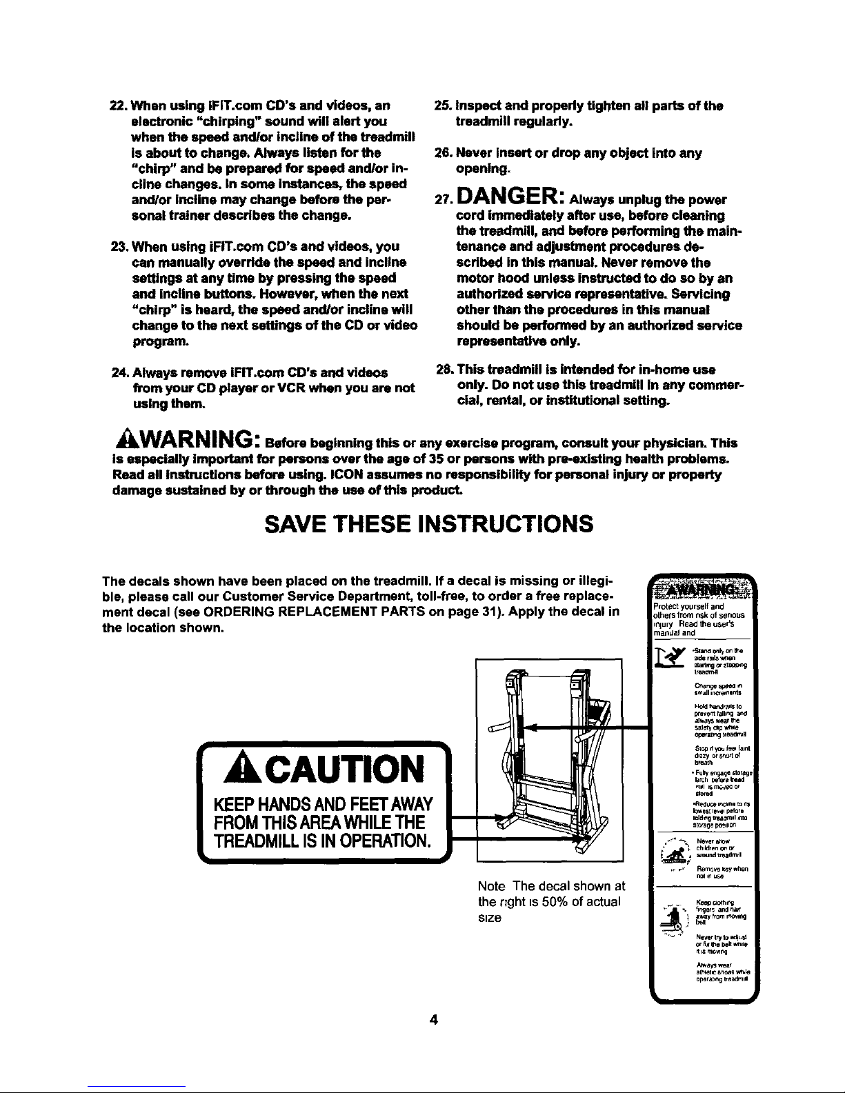
The decals shown have been placed on the treadmill. If a decal is missing or illegi-
ble, please call our Customer Service Department, toll-free, to order a free replace-
ment decal (see ORDERING REPLACEMENT PARTS on page 31). Apply the decal in
the location shown.
AkCAUTION
KEEPHANDSANDFEETAWAY
FROMTHISAREAWHILETHE
TREADMILLISINOPERATION.
I
Note The decal shownat
the right is 50% ofactual
size
4
Protect yourself and
othelS from nsk of senous
injury Read the use{'s
ma[_daJand
C_e spceo _
Small in_vnlnts
H_d ;,andraltS to
prevent fall_g
aJ_ays _ the
Salet_ _p _'_e
Op_sl_g "_eadr_R
Slop d _ tsm f_.nt
dlz;-/ o__*_c.I of
brea_h
• Ful_ enga_ *lorage
_afCh Defoe Bead
toNI _ rr_._o or
stored
-Reduce incmne_o
k;w_ IB_el_elore
_/_ i ch_kl.....
_ _¥ from _
d m m_lng
ol_rat _,_ _eal:_lll
Page 5
BEFORE YOU BEGIN
Thank you for selectingthe revolutionary NordicTrack*
E 3200 treadmill. The E 3200 treadmill combines ad-
vanced technology with innovative design to help you
get the most from your exercise program in the conve-
nience of your home. And when you're not exercising,
the unique E 3200 treadmill can be folded up, requiring
less than half the floorspace of other treadmills.
For your benefit, read this manual carefully before
using the treadmill, if you have additional questions,
please call our Customer Service Department toll-free
at 1-888-825-2588, Monday through Friday, 6 a.m.
until 6 p.m. Mountain Time (excluding holidays). To
help us assist you, please note the product model
number and serial number before calling. The model
number of the treadmill is NTL16920. The serial num-
ber can be found on a decal attached to the treadmill
(see the front cover of this manual for the location).
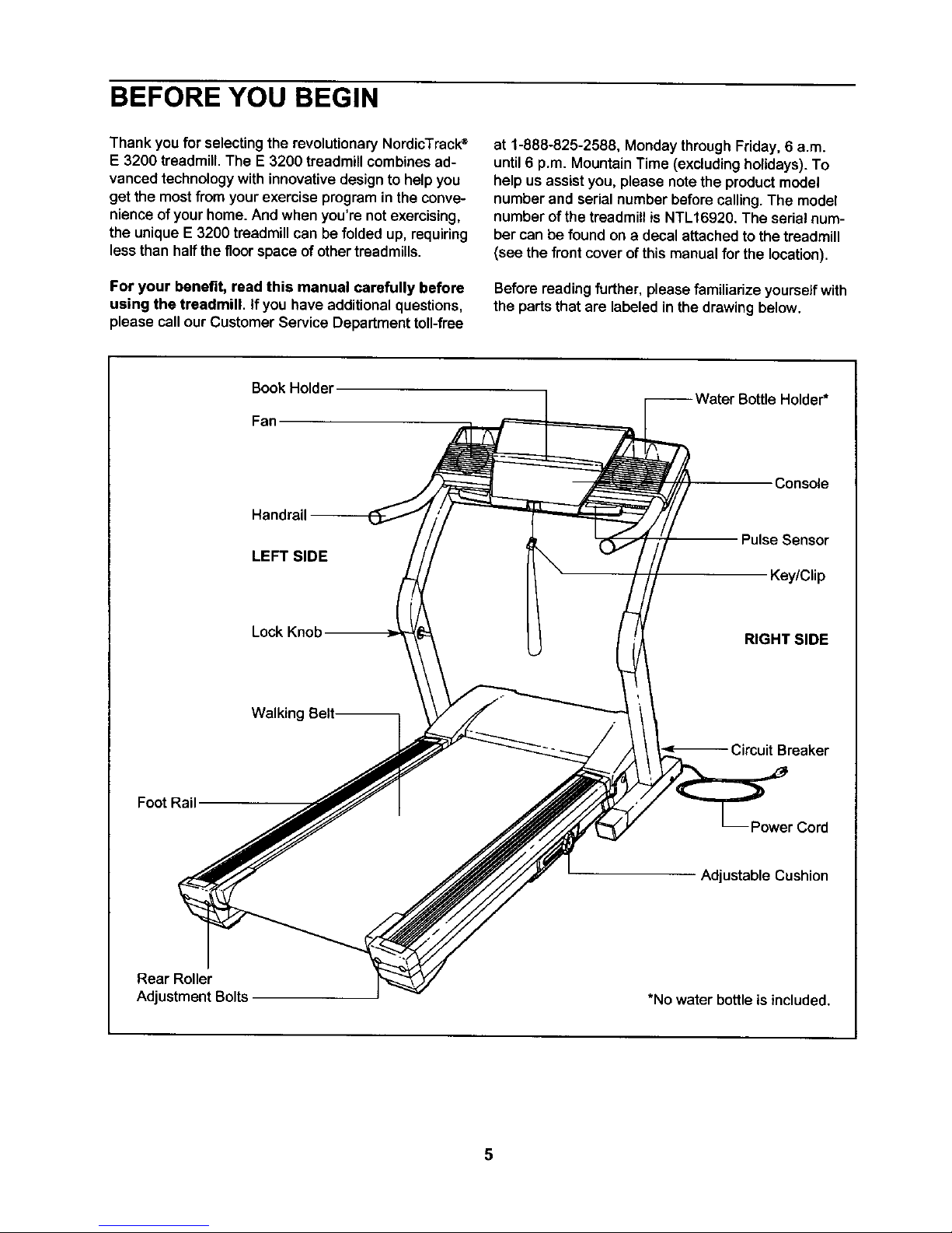
Before reading further, please familiarize yourself with
the parts that are labeled in the drawing below.
Book Holder
Fan
BottleHolder*
Console
LEFT SIDE
Pulse Sensor
Key/Clip
Lock Knob
RIGHT SIDE
Walking
Circuit Breaker
Foot Rail
Adjustable Cushion
Rear Roller
Adjustment Bolts
*No water bottle is included.
5
Page 6
ASSEMBLY
Assembly requires two people. Set the treadmill in a cleared area and remove all packing matedals. Do not
dispose of the packing materials until assembly is completed. Assembly requires the included allen wrench.._
and your own phillips screwdriver _, wire cutters _, and rubber mallet c::::_:_.
Note: The undersideof the treadmillwalking belt is coated with high-performance lubricant. During shipping,a
small amount of lubricant may be transferred to the top of the walking belt or the shipping carton. This is a normal
condition and does not affect treadmill performance. If there is lubricant on top of the walking belt, simply wipe off
the lubricant with a soft cloth and a mild, non-abrasive cleaner.
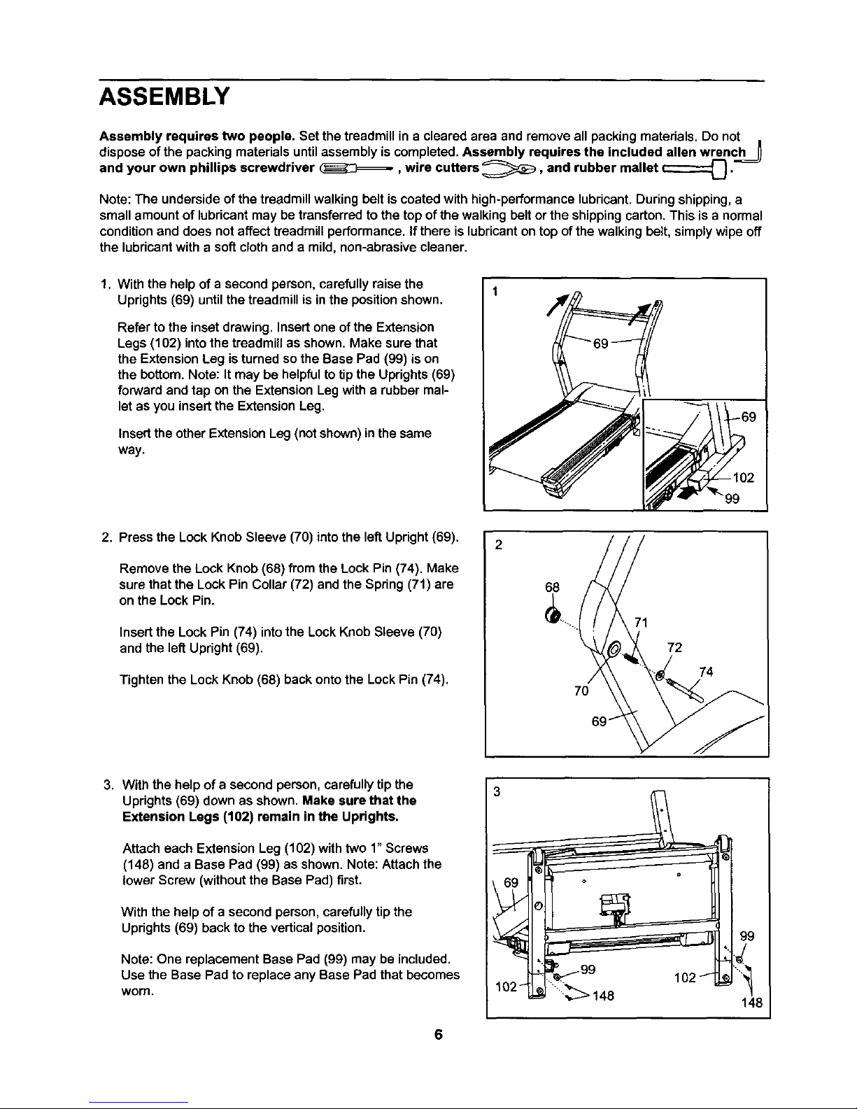
1. With the help of a second person, carefully raise the
Uprights (69) until the treadmill is in the position shown.
Refer to the inset drawing. Insert one of the Extension
Legs (102) into the treadmill as shown. Make sure that
the Extension Leg is turned so the Base Pad (99) is on
the bottom. Note: It may be helpful to tip the Uprights (69)
forward and tap on the Extension Leg with a rubber mal-
let as you insert the Extension Leg.
Insert the other Extension Leg(not shown)in the same
way.
99
2. Press the Lock Knob Sleeve (70) intothe left Upright (69).
Remove the Lock Knob (68) from the Lock Pin (74). Make
sure that the Lock Pin Collar (72) and the Spring (71) are
on the Lock Pin.
Insert the Lock Pin (74) into the Lock Knob Sleeve (70)
and the left Upright (69).
Tighten the Lock Knob (68) back onto the Lock Pin (74).
2
68
70
72
74
3. With the help of a second person, carefullytip the
Uprights (69) down as shown. Make sure that the
Extension Legs (102) remain in the Uprights.
Attach each Extension Leg (102) with two 1"Screws
(148) and a Base Pad (99) as shown. Note: Attach the
lower Screw (without the Base Pad) first.
With the help of a second person, carefully tip the
Uprights (69) back to the vertical position.
Note: One replacement Base Pad (99) may be included.
Use the Base Pad to replace any Base Pad that becomes
worn,
3
99
* _tq
148
6
Page 7
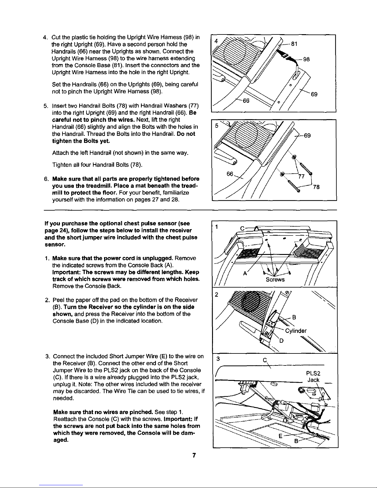
4. Cut the plastic tie holding the Upright Wire Harness (96) in
the right Upright (69). Have a second person hold the
Handrails (66) near the Uprights as shown. Connect the
Upright Wire Harness (98)to the wire harness extending
from the Console Base (81). Insert the connectors and the
Upright Wire Harness into the hole in the right Upright.
Set the Handrails (66) on the Updghts (69), being careful
not to pinch the Upright Wire Harness (98).
5. Insert two Handrail Bolts (78) with Handrail Washers (77)
into the right Upright (69) and the right Handrail (66). Be
careful not to pinch the wires. Next, liftthe right
Handrail (66) slightlyand align the Boltswiththe holesin
the Handrail.Thread the Boltsintothe Handrail, Do not
tighten the Bolts yet.
Attach the left Handrail (not shown) in the same way.
Tighten all four Handrail Bolts (78).
6. Make sure that all parts are properly tightened before
you use the treadmill. Place a mat beneath the tread-
mill to protect the floor. For your benefit, familiarize
yourself with the information on pages 27 and 28,
78
If you purchase the optional chest pulse sensor (see
page 24), follow the steps below to install the receiver
and the short jumper wire included with the chest pulse
sensor.
1. Make sure that the power cord is unplugged. Remove
the indicatedscrewsfromthe ConsoleBack (A).
Important: The screws may be different lengths. Keep
track of which screws were removed from which holes.
Removethe ConsoleBack.
2. Peel the paper off the pad on the bottom of the Receiver
(B). Turn the Receiver so the cylinder is on the side
shown, and press the Receiver into the bottomofthe
ConsoleBase (D) in the indicatedlocation.
3. Connect the included Short Jumper Wire (E) to the wire on
the Receiver (B). Connect the other end of the Short
Jumper Wire to the PLS2 jack on the back of the Console
(C). If there is a wire already plugged into the PLS2 jack,
unplug it. Note: The other wires included with the receiver
may be discarded. The Wire Tie can be used to tie wires, if
needed.
Make sure that no wires are pinched. See step 1.
Reattach the Console (C) with the screws. Important: If
the screws are not put back into the same holes from
which they were removed, the Console will be dam-
aged.
Screws
C
\
\
PLS2
Jack
7
Page 8
OPERATION AND ADJUSTMENT
THE PERFORMANT LUBETM WALKING BELT
Your treadmillfeatures a walking belt coated with
PERFORMANT LUBETM, a high-performance lubricant.
IMPORTANT: Never apply silicone spray or other
substances to the walking belt or the walking plat-
form. Such substances will deteriorate the walking
belt and cause excessive wear.
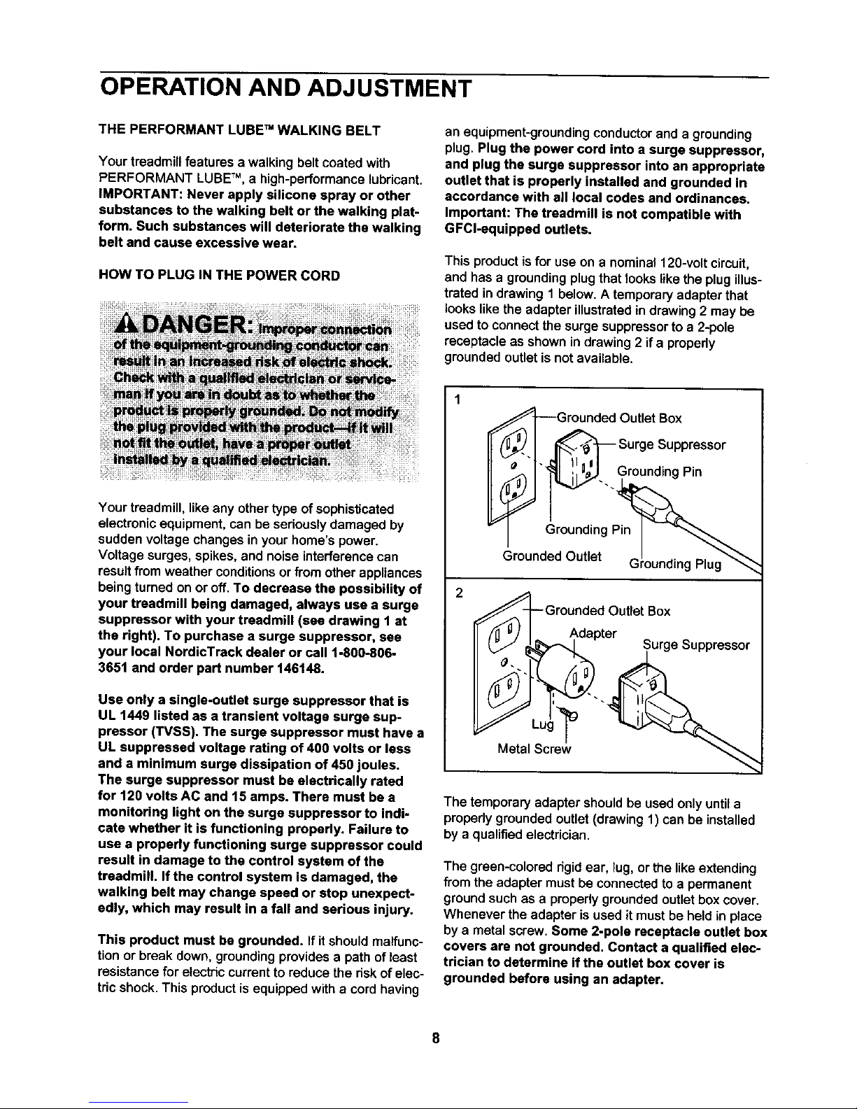
HOW TO PLUG IN THE POWER CORD
an equipment-grounding conductor and a grounding
plug,Plug the power cord into a surge suppressor,
and plug the surge suppressor into an appropriate
outlet that is properly installed and grounded in
accordance with all local codes and ordinances.
Important: The treadmill is not compatible with
GFCI-equipped outlets.
This product is for use on a nominal 120-voltcircuit,
and has a grounding plug that lookslike the plug illus-
trated in drawing 1 below. A temporary adapter that
looks like the adapter illustrated in drawing 2 may be
used to connect the surge suppressor to a 2-pole
receptacle as shown in drawing 2 if a properly
grounded outlet is not available.
Your treadmill, like any other type of sophisticated
electronic equipment, can be seriously damaged by
sudden voltage changes in your home's power.
Voltage surges, spikes, and noise interference can
result from weather conditions or from other appliances
being turned on or off. To decrease the possibility of
your treadmill being damaged, always usa a surge
suppressor with your treadmill (sea drawing 1 at
the right). To purchase a surge suppressor, see
your local NordicTrack dealer or call 1-800-806-
3651 and order part number 146148.
Use only a single-outlet surge suppressor that is
UL 1449 listed as a transient voltage surge sup-
pressor (TVSS). The surge suppressor must have a
UL suppressed voltage rating of 400 volts or less
and a minimum surge dissipation of 450 joules.
The surge suppressor must be electrically rated
for 120 volts AC and 15 amps. There must be a
monitodng light on the surge suppressor to indi-
cate whether it is functioning properly. Failure to
use a properly functioning surge suppressor could
result In damage to the control system of the
treadmill. If the control system is damaged, the
walking belt may change speed or stop unexpect-
edly, which may result in a fall and serious injury.
This product must be grounded. If it should malfunc-
tionor break down,grounding providesa path of least
resistance for electric currentto reduce the risk of elec-
tric shock. This product is equipped with a cord having
_Grounded Outlet Box
[_._ _ Surge Suppressor
[L_ _" _. Grounding Pin
G ounding Pin_
Grounded Outlet GIrounding Plug"_
Grounded Outlet Box
Adapter ^
II { °./" _P,,.-,,_I Surge _uppressor
Metal Screw
The temporary adapter shouldbe used only untila
properly grounded outlet (drawing 1) can be installed
by a qualified electrician.
The green-colored dgid ear, lug, or the like extending
from the adapter must be connected to a permanent
ground such as a propedy grounded outlet box cover.
Whenever the adapter is used it must be held in place
by a metal screw, Some 2-pole receptacle outlet box
covers are not grounded. Contact a qualified elec-
trician to determine if the outlet box cover is
grounded before using an adapter.
Page 9
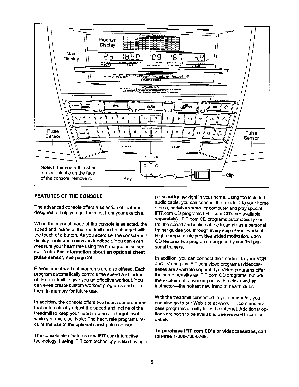
Pulse Pulse
Sensor Sensor
Note: If there is a thin sheet
of clear plastic on the face
of the console, remove it.
Key
FEATURES OF THE CONSOLE
The advanced console offers a selection of features
designed to help you get the most from your exercise.
When the manual mode of the console is selected, the
speed and incline of the treadmill can be changed with
the touch of a button. As you exercise, the console will
display continuous exercise feedback. You can even
measure your heart rate using the handgrip pulse sen-
sor. Note: For information about an optional chest
pulse sensor, see page 24.
Eleven preset workoutprograms are also offered.Each
program automaticallycontrols the speed and incline
ofthe treadmill to giveyou an effectiveworkout. You
can even create customworkout programsand store
them in memoryfor future use.
In addition,the consoleoffers two heart rate programs
that automaticallyadjustthe speed and inclineof the
treadmill to keep your heart rate near a target level
while you exercise. Note: The heart rate programs re-
quire the use of the optional chest pulse sensor.
The console also featuresnew iFIT.com interactive
technology.HavingiFIT.com technologyislikehavinga
personal trainer right in your home.Usingthe included
audio cable, you can connect the treadmill to your home
stereo, portable stereo, or computer and play special
iFIT.com CD programs (iFIT.com CD's are available
separately). IFIT.com CD programs automatically con-
trol the speed and incline of the treadmill as a personal
trainer guides you through every step of your workout.
High-energy music provides added motivation. Each
CD features two programs designed by certified per-
sonal trainers.
In addition,you can connectthe treadmillto your VCR
and TV and play iFIT.com video programs (videocas-
settes are available separately). Video programs offer
the same benefits as iFIT.com CD programs, but add
the excitement of working out with a class and an
instructor--the hottest new trend at health clubs.
With the treadmill connected to your computer,you
can also go to our Web site at www.iFIT.com and ac-
cess programs directly from the internet.Additional op-
tions are soon to be available. See www.iFIT.com for
details.
To purchase iFIT.com CD's or videocassettes, call
toll-free 1-800-735-0768.
9
Page 10
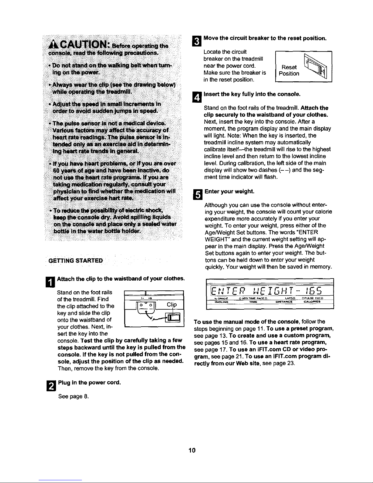
GETTING STARTED
D Attach the clip to the waistband of your clothes.
Stand on the footrails
of thetreadmill.Find
the clip attachedtothe
key and slide the clip
ontothe waistbandof
yourclothes. Next, in-
sert the key intothe
console.Test the clip by carefully taking a few
steps backward until the key is pulled from the
console. If the key is not pulled from the con-
sole, adjust the position of the clip as needed.
Then, remove the key fromthe console.
B Plug in the power cord.
See page 8.
[]Move the circuit breaker to the reset position.
Locatethe circuit
breaker on the treadmill
near the power cord.
Make sure the breaker is
in the reset position.
Reset
Position
L_ Insert the key fully into the console.
Stand on the footrails ofthetreadmill.Attach the
clip securely to the waistband of your clothes.
Next, insertthe key intothe console.After a
moment,the programdisplayand the main display
will light.Note: When the key is inserted,the
treadmillinclinesystem may automatically
calibrateitself--the treadmillwill risetothe highest
inclinelevel and then returnto the lowest incline
level. Dudngcalibration,the left side of the main
displaywillshowtwo dashes (- -) and the seg-
ment time indicatorwillflash.
[]Enter your weight.
Althoughyou can use the consolewithoutenter-
ingyour weight, the consolewillcount your calorie
expendituremore accuratelyifyou enter your
weight. To enteryour weight,press eitherofthe
Age/Weight Set buttons.The words=ENTER
WEIGHT" and the currentweightsettingwillap-
pear in the main display.Press theAge/Weight
Set buttonsagain toenter yourweight. The but-
tonscan be held downto enteryour weight
quickly.Your weightwillthen be saved in memory.
I[E _ T L_ i= Tt" L=T i_C
To use the manual mode of the console, followthe
steps beginningon page 11.To use a preset program,
see page 13. To create and use a custom program,
see pages 15 and 16.To use a heart rate program,
see page 17. To use an iFIT.com CD or video pro-
gram, see page 21. To use an iFIT.com program di-
rectly from our Web site, see page 23.
10
Page 11
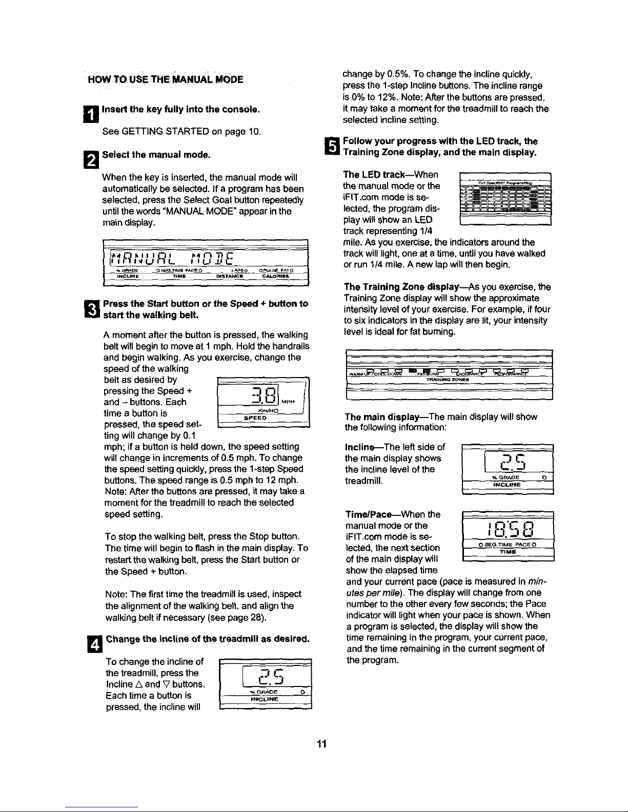
HOW TOUSE _HE MANUAL MODE
D Insert the key fully into the console.
See GETTING STARTED on page 10.
B
Select the manual mode.
When the key is inserted,the manual mode will
automatically be selected. If a program has been
selected, press the Select Goal button repeatedly
until the words "MANUAL MODE" appear in the
main display.
_4 kill I
II I I!"_I_U IL_L 1_4 f--I Tl_"__I U J-I C
_FU_[_II O_TIME P_GEO L_PS O OP*JLSE FAYO
iI_CLINI_ TIME Ot_tAl_lCm C/_.OmmS
[]Press the Start button or the Speed + button to
start the walking belt.
A moment after the button is pressed, the walking
belt will begin to move at I mph. Hold the handrails
and begin walking. As you exercise, change the
speed of the walking
pressingthe Speed + "1 L--J
and - battens. Each MP.
time a button is I_ ==_-"'_°
pressed, the speed set-
ting will change by 0.1
mph; if a button is held down, the speed setting
will change in increments of 0.5 mph. To change
the speed setting quickly, press the 1-step Speed
buttons. The speed range is 0.5 mph to 12 mph.
Note: After the buttons are pressed, it may take a
moment for the treadmill to reach the selected
speed setting.
To stop the walking belt, press the Stop button.
The time will begin to flash in the main display. To
restart the walking belt, pressthe Start button or
the Speed +button.
Note: The first time the treadmill is used, inspect
the alignment of the walking belt, and align the
walking belt if necessary (see page 28),
B Change the inCline of the treadmill as desired.
To change the incline of
the treadmill, press the
Incline A and Wbuttons.
Each time a button is
pressed, the incline will
.'3.C
C.J
_/. GRADE O
INCLINE
change by 0.5%. To change the inclinequickly,
press the 1-stepIncline buttons. The incline range
is 0% to 12%. Note: After the buttons are pressed,
it may take a moment for the treadmill to reach the
selected incline setting.
_._ Follow your progress with the LED track, the
Training Zone display, and the main display.
The LED track--When
the manual mode orthe
iFIT.cem mode isse-
lected, the program dis-
play wit! show an LED
track representing 1/4
m mm Ilim
mile. As you exercise, the indicators around the
track will light, one at atime, until you have walked
or run 1/4 mile. A new lap will then begin.
The Training Zone display--As you exercise, the
Training Zone display willshowthe approximate
intensitylevel ofyour exercise.For example, iffour
tosix indicatorsinthe display are lit,your intensity
level is idealfor fat burning.
t .... ;
The main display--The main display willshow
the following information:
Incline_The left side of
the main displayshows
the inclinelevel of the
treadmill.
L..J
% GRAI_E 0
INCLINE
Time/Pace--When the
manualmode orthe
iFIT.cem mode isse-
lected,the nextsection
ofthe maindisplaywill
showtheelapsed time
and your current pace (pace is measured in min-
utespermile). The displaywill change from one
number to the other every few seconds; the Pace
indicator will light when yourpace is shown. When
a program is selected, the display will show the
time remaining in the program, your current pace,
and the time remaining in the current segmentof
the program.
11
Page 12

OstanceLapsTheL L
center section of the ! 1"3 !.--J
[U"!
main display shows the
distance that you have o ",STA"CE_"SOOP
walked and the number
of 1/4-mile laps you
have completed. The display will change from one
number to the other every few seconds; the Laps
indicator will light when the number of laps is
shown.
Calories/Puls_
When you are not _ I._ "-I
using the handgrip !
pulse sensor, the next OPUL_FATO
CALORIES
sectionof the main dis-
play will show the ap-
proximate numbers of calories and fat calories
you have burned (see FAT BURNING on page
29). The display will change from one number to
the other every few seconds; the Fat indicator will
light when the number of fat calodes is shown.
When you are using the handgdp pulse sensor,
the display will show your heart rate (see step 6 at
the right).
Speed--The right side
ofthe main display
shows the speed ofthe
walking belt.
I SpEIEO
Noteecons°nt, J1
display speed and dis-
tance in either miles or MP
kilometers. To find ATO pE_
s
which unit of measure-
ment is selected, hold
down the Stop button whileinsertingthe key into
the console. An "E" for Englishmiles or an "M" for
metric kilometers will appear on the right side of
the main display. Press the Speed + button to
change the unit of measurement. When the de-
sired unit of measurement is selected, remove the
key and then reinsert it. Note: For simplicity, all
instructions in this manual refer to miles.
To reset the main display, press the Stop button,
remove the key, and then reinsert the key.
B
Measure your heart rate, if desired.
To measure your
heart rate, stand
on the foot rails
and place your
hands on the metal
contacts on the
handrail. Your Metal Contact.,
palms must be rest-
ingon the upper _ _ 9
contacts, and your
O pULSE FATO
fingers must be CALO.,ES
touching the lower
contacts---avoid
moving your hands. When your pulse is detected,
the Pulse indicator will light and then your heart
rate will be shown in the main display, For the
most accurate heart rate reading, continue to
hold the contacts for about 15 seconds.
B Turn on the fans if desired.
To turnon the fans at low speed, press the Fans
button.To turnon the fans at highspeed, press
the Fans buttona secondtime. To turn offthe
fans, press the Fans buttons a thirdtime. Note:
Any time thatthe walkingbelt isstoppedfor a few
minutes,thefans will automatically turnoff.
B When you are finished exercising, stop the
walking belt and remove the key.
Step ontothe foot rails, press the Stop button, and
adjust the inclineof the treadmill to the lowest level.
The incline must be at the lowest level when
the treadmill is raised to the storage position or
the treadmill will be damaged. Next, removethe
key from the consoleand putitin a secureplace.
Note: If the displays and indicators on the con-
sole remain lit after the key is removed, the
console is in the "dsmo" mode. See page 24
and turn off the demo mode.
When you are finished using thetreadmill,move
the on/off switch near the power cord to the off
position and unplug the power cord.
12
Page 13

_! Insert the key fully into the console.
See GETTING STARTED on page 10.
_1 Select the desired preset program.
The consoleofferseleven presetprograms_three
programsthat focuson weight loss,five programs
designedfor aerobic exercise, and three pro-
grams for high-performanceconditioning,
When the key is inserted, the manual mode willbe
selected. To select one of the preset programs,
first press the Select Goal button repeatedly until
the words "WEIGHT LOSS," "AEROBIC," or
"PERFORMANCE" appear in the main display.
£1GH 055
% GP_t_s O_GTtMS P_CEO L_,PSO OPULSE F_'TO
INCUNS TIME DIST_CE C_OmlES
Next, press the Select Course button repeatedly
to select one of the weightloss, aerobic, or perfor-
mance programs. For example, if the words
"WEIGHT LOSS" appear in the main display, you
can selectthe 20-minute Pyramid, 35-minute
Pyramid, or 20-minute Fat Burn program.
P
_ _Fl*_J_ll. O_GTIME P_EQ t_SO OpULSE FAI'O
Three seconds after a preset program is selected,
the name of the selected program, the maximum
speed setting for the program, the maximum in-
cline setting for the program, and the total program
time will begin to scroll across the main display.
The program dis-
play willshowthe
speed settings of
the program you
have selected.
Note: If you have
Foo°.o°o,..ko
selected a program with more than twelve seg-
ments,the display willshow only the first twelve
speed settings.
1_1 Press the Start button or the Speed + button to
start the program.
A moment after the button is pressed, thetread-
mill will automaticallyadjust to the first speed and
incline settings of the program. Hold the handrails
and begin walking.
Each program is divided into several time seg-
ments of different lengths. (The main display
shows both the time remaining in the program and
the time remaining in the current segment of the
program.) One speed setting and one incline set-
ting are programmed for each segment. (The
same speed setting and/or incline setting may be
programmed for consecutive segments.) The
speed setting for
the first segment is
shown in the flash- Current Segment
ing Current
Segment column of
the program dis-
play. (The incline
settingsare not
shown in the program display.) The speed set-
tings for the next several segments are shown in
the columns to the right.
When onlythree seconds remain in the firstseg-
mentof the program, both the Current Segment
column and the column to the right will flash and a
series of tones will sound. In addition, if the speed
and/or incline of the treadmill is aboutto change,
the speed setting and/or incline setting will flash in
the main display to alert you. When the first seg-
ment is completed, all speed settingswill move
one column to the left. The speed setting for the
second segment will then be shown in the flashing
Current Segment column end the treadmill will au-
tomatically adjust to the speed and incline settings
for the second segment. Note: If all of the indica-
tors in the Current Segment column are lit after the
speed settings have moved to the left, the speed
settings will move downward so that only the high-
est indicators appear in the program display. If
some of the indicators in the Current Segment col-
umn are not lit when the speed settings move to
the left again, the speed settings will move back
up.
The program will continue in this way until the
speed setting for the last segment is shown in the
Current Segment column and no time remains in
the program. The walking belt will then slow to a
stop.
13
Page 14

If the speed or incline settingistoo high or too low
during the program, you can manually override
the setting by pressing the Speed or incline but-
tons on the console. Every few times one of the
Speed buttons is pressed, an additional indicator
will light or darken in the Current Segment column.
(If any of the columns to the right of the Current
Segment column have the same number of lit indi-
cators as the Current Segment column, an addi-
tional indicator may light or darken in those
columns as well.) Note: If you manually adjust the
speed settingso that all of the indicators in the
Current Segment column are Ut,the speed settings
in the program display will not move downward as
described above. Note: If you manually override
the speed or incline setting, when the next seg-
ment begins, the treadmill will automatically
adjust to the speed and incline settings for the
next segment.
To stopthe program temporarily,press the Stop
button. The time will begin to flash inthe main dis-
play. To restart the program, press the Start button
or the Speed + button. The walking belt will begin
to move at 1 mph. When the next segment begins,
the treadmill will automatically adjust to the speed
and incline settings for the next segment. To end
the program, press the Stop button, remove the
key, and then reinsert the key.
L_ Follow your progress with the displays.
See step 5 on page 11.
1_! Measure your heart rate if desired.
See step 6 on page 12.
r_Turn on the fans if desired.
See step 7 on page 12.
B When the program has ended, remove the key.
Step ontothe foot rails and make sure that the in-
cline of the treadmill is at the lowest level. Next,
removethe key from the consoleand putit in a se-
cure place, Note: If the displays and indicators
on the console remain lit after the key is re-
moved, the console is in the "demo" mode.
See page 24 and tum offthe demo mode.
When you are finishedusingthe treadmill, move
the on/off switchnear the power cord to the off
position and unplug the power cord.
14
Page 15

HOW TO CREATE CUSTOM PROGRAMS
B Insert the key fully into the console.
See GETTING STARTED on page 10.
B Select one of the custom programs.
When the key is inserted,the manualmode willbe
selected. To select a customprogram,first press
the Select Goal buttonrepeatedly untilthe words
"CUSTOM PROGRAM" appear inthe main dis-
play.
PP,OGP t; l
I-US i Ull
_o_ O_TIM_ PAtiO _50 OPUL_ FAT_
INGUNE TIME DISTDJ4CE CALORI_
Next, press the Select Course button repeatedly to
select the Leam 1 or Learn 2 program.
EnP"' ' -3 ,, ,. ,
! _1 l J. l.J
IN_LIN_ TiME DIGT_ICE CAI_O_I EB
Three secondsafter a custom program is selected,
the name of the selected program and the total
program time will begin to scroll across the main
display.
Note: If the custom program has not yet been
defined, one to three columns of indicators
will be lit in the program display. If more than
three columns of indicators are lit, see HOW
TO USE CUSTOM PROGRAMS on page 16.
B Prees the Start button or the Speed + button
and program the desired speed and incline
settings.
A moment after the button is pressed, the walking
belt will begin to move. Hold the handrails and
begin walking.
Refer to the program display. Each custom pro-
gram is divided intoone-minute segments. One
speed setting and one incline setting can be pro-
grammed for each segment. The speed setting for
the first segment
will be shown in the
flashing Current Current Segment
Segment column of
the program dis-
play. (The incline
settings are not
shown in the pro-
gram display.) To program a speed setting and an
incline setting for the first segment, simply adjust
the speed and incline of the treadmill as desired
by pressing the Speed and Incline buttons. Every
few times one of the Speed buttons is pressed, an
additional indicator will light or darken in the
Current Segment column.
When the first segmentof the program iscom-
pleted, the current speed settingand the current
incline setting will be stored in memory. The three
columns of indicators will then move one column
to the left, and the speed setting for the second
segment will be shown in the flashing Current
Segment column. Program a speed settingand an
incline setting for the second segment as de-
scribed above. Note: After the third segment is
completed, the columns of indicators in the pro-
gram display will no longer move to the left.
Instead, each time a segment is completed, the
flashing Current Segment column will move one
column to the right. If the Current Segment col-
umn reaches the right side of the program display,
when the current segment is completed all
columns of indicators in the program display will
move three columns to the left.
Continue programming speed and incline settings
for as many segments as desired; custom pro-
grams can have up to forty segments. When you
are finished with your workout, press the Stop but-
ton twice. The speed and incline settings that you
have programmed and the number of segments
that you have programmed will then be saved in
memory.
B When the program has ended, remove the key.
See step 7 on page 14.
15
Page 16

B Insert the key fully into the console.
See GETTING STARTED on page 10.
B Select one of the custom programs.
When the key is inserted,the manualmode willbe
selected. To select a customprogram,first press
the Select Goal buttonrepeatedly untilthewords
=CUSTOM PROGRAM" appear inthe main dis-
play.Next, presstheSelect Coursebuttonrepeat-
edlytoselectthe Learn1 or Learn2 program.
Three seconds after a custom program isse-
lected, the name of the selected program and the
total programtime will begin to scrollacrossthe
main display.
The program display will show the firstspeed set-
tingsof the program you have selected (see the
drawingbelow). Note: If only three columns of
indicators are lit in the program display, see
HOW TO CREATE A CUSTOM PROGRAM on
page 15.
B Press the Start button or the Speed + button to
start the program.
A moment after the button is pressed, the tread-
mill willautomaticallyadjustto the first speed and
incline settingsthat you programmedpreviously.
Holdthe handrailsand beginwalking.
Each program is divided intoseveral one-minute
segments. (The main display shows both thetime
remaininginthe programand the timeremaining
inthe currentsegment ofthe program.)One
speed settingand one inclinesetting are pro-
grammedfor each segment.The speed settingfor
the firstsegment isshown inthe flashingCurrent
Segment column
ofthe program
display.(The in- CurrentSegment
clinesettings are
not shownin the
programdisplay.)
The speed set-
tingsfor the next
several segmentswill be shown inthe columns to
the right.
When only three seconds remain inthe firstseg-
ment ofthe program, both the Current Segment
columnand the columntothe rightwiltflash, a se-
riesoftones willsound, the speed settingand the
inclinesettingwillflash inthe main display,and all
speed settings will move one columnto the left.
The speed setting for the second segmentwill then
be shown in the flashing Current Segment column
and the treadmill wil! automatically adjust to the
second speed and incline settings that you pro-
grammed previously.
The program willcontinue until the speed setting
for the last segment isshownin the Current
Segment columnand notime remainsin the pro-
gram. The walkingbelt willthen slow to a stop.
If desired, you can redefinetothe program while
using it. To change the speed or incline setting
during the current segment, simplypressthe
Speedor Inclinebuttons.When thecurrentsegment
iscompleted,thenew settingwillbe saved inmem-
ory.To increase the length of the program, first
waituntilthe programiscompleted.Then, pressthe
Startbutton,and programspeedandinclinesettings
for as manyadditionalsegmentsas desired.(Note:
While you are adding segments to the program,
the speed settingsinthe programdisplaywillnot
move tothe left. Instead, each time a segment is
completed,the flashing Current Segment column
willmove one column to the dght. If the Current
Segment columnreaches the rightside ofthe pro-
gram display,when the currentsegment is com-
pletedall columnsof indicatorsin theprogram dis-
play willmove three columnsto the left.) When
you have added as manysegmentsas desired,
press the Stop button twice. To decrease the
length of the program, presstheStopbuttontwice
at anytime beforetheprogramiscompleted.
To stopthe program temporarily, press the Stop
button. The time will begin to flash inthe main dis-
play. To restart the program, press the Start but-
ton or the Speed + button. To end the program,
press the Stop button, remove the key, and then
reinsert the key.
B Follow your progress with the displays.
See step 5 on page 11.
[]When the program has ended, remove the key.
See step 7 on page 14.
16
Page 17

HOW TO USE HEART PATE PROGRAMS
Heart rate programs automatically adjust the speed
and incline of the treadmill to keep your heart rate near
a target level while you exercise. Note: You must
wear the optional chest pulse sensor (see page 24)
to use the heart rate programs.
Followthe steps below to use a heart rate program.
_lPut on the optional chest pulse sensor.
To put on the chest pulse sensor, see the instruc-
tions included with the chest pulse sensor.
F_I Insert the key fully into the console.
See GETTING STARTED on page 10.
1_1 Select a heart rate program.
When the key is inserted, the manual mode will be
selected.To select a heart rate program,first
press the Select Goal buttonrepeatedly untilthe
words"HEART RATE" appear in the main display.
IHEnPT RRTE ]
% GRAE"E OS_GT_MC P_so LAFsO OPUL_E FATO
INCLIN_ TIME DI_TN_ _ CAI_)R[E_
Next, press the Select Course button until the words
"PULSE DRIVEN 1" or "PULSE DRIVEN 2" appear.
liP'" 5E E t
IlL 11 t,I I --t,I
-_ G_DE o _G.TIMF _,cE o L_'_ o m
o PULSe FATO
INCLINE TIME _I_'I*A_IC E _ JLLOR i S 6
/
During heart rate
programs, the pro-
gram display will
show a graphic that
represents your
heart rate. Each
_mD_D_OD_ID_
m_m_m_mEmm_mD
time a heartbeat is detected, an additional peak
will appear.
L_ Enter your age and a maximum speed setting.
Three seconds after a heart rate program is se-
lected, the words "ENTER AGE" and the current
age setting will appear in the main display. You
must enter your age to use a heart rate program.
If you have already entered your age, press the
Start button (pressing the button will not start the
program at this time). If you have not entered your
age, press the AgeANeight Set buttons to enter
your age. The buttons can be held down to enter
your age quickly. Then, press the Start button.
Once you have entered your age, it will be saved
in memory.
IEttTER nGE--28
_, OR*_D_ O_GT6ME PACE O _S O OPtJL_ FAt O
INCLINE _ME D_STANCE CALOm_
After you have entered your age, the words
"ENTER MAX SPEED" and the maximum speed
setting of the program will appear in the main dis-
play. If desired, press the Speed buttons or the
1-step Speed buttons to change the maximum
speed setting.
IEt:TE,q r;,q" SPEEd-- t
_GRAD_ O_G.IME P"CEO L_PSO OPUL_SE _:AT o
INC_NE _IME _STANCE CALOmES
17
Page 18

_.'._ Press the Start button or the Speed + button to
start the program.
A moment after the button is pressed, the tread-
mill willautomatically adjust tothe first speed and
incline settingsof the program. Hold the handrails
and begin walking.
Each heartrate program is divided into severaltime
segments of different lengths. (The main display
shows both the time remaining in the program and
the time remaining in the current segment of the
program.) One target heart rate setting is pro-
grammed for each segment.
During each segment, the console will regularly
compare your heart rate to the current target heart
rate setting. If your heart rate is too far below or
above the target heart rate setting, the speed of
the treadmill will automatically increase or de-
crease to bring your heart rate closer to the target
heart rate setting. If the speed reaches the maxi-
mum speed setting of the program (see step 4 on
page 17) and your heart rate is still too far below
the current target heart rate setting, the incline of
the treadmill wildalso increase to bring your heart
rate closer to the target heart rate setting.
During the lastthree secondsof each segment, a
series of tones willsound and the speed setting
and/or the incline setting will flash in the main
display.
The program willcontinueuntil no time remains in
the program. The walking belt will then slow to a
stop.
If the speed or incline setting is too high or too low
during the program, you can adjust the setting
with the Speed or Incline buttons. However, each
time the console compares your heart rate to the
current target heart rate setting, the speed and/or
incline of the treadmill may automatically change
to bring your heart rate closer to the target heart
rate setting.
If your pulse is not detected during the program,
the letters "PLS" will flash in the main display and
the speed and incline of the treadmill may auto-
matically decrease until your pulse is detected. If
this occurs, refer to the instructions included with
the optional chest pulse sensor.
To stopthe program at any time, press the Stop
button. Heart rate programs shouldnot be stopped
temporarily and then restarted. To use a heart rate
program again, reselect the program and start it at
the beginning.
Follow your progress with the displays.
See step 5 on page 11.
B Turn on the fans if desired.
See step 6 on page 12.
_] When the program has ended, remove the key.
See step7 on page 14.
18
Page 19

HOW TO CONNECT YOUR PORTABLE STEREO
Note: If your stereo has an RCA-type AUDIO OUT
jack, see instruction A below. If your stereo has a
To use iFit.com CD's, the treadmillmustbe connected
to yourportable CD player,portable stereo, home
stereo, or computerwith CD player. See this page and
page 20 for connectinginstructions.To use iFIT.com
videocaesettes, the treadmillmust be connectedto
yourVCR. See page 21 for connectinginstructions.To
use iFIT.com programs directly from our Web site,
the treadmillmust be connectedto your home com-
puter.See page 20 for connectinginstructions.
HOW TO CONNECT YOUR PORTABLE CD PLAYER
Note: If your CD player has separate LINE OUT and
PHONES jacks, see instruction A below. If your CD
player has only one jack, see instruction B.
A. Plug one end of the audio cable intothejack on the
front of the treadmill near the power cord. Plug the
other end of the cable into the LINE OUT jack on
your CD player. Plug your headphones into the
PHONES jack.
A
LINEC4JT@ i _ PHONES i
........................
i @ i Audio LU . "
i:ri_ i--o-iI Cable pnones
L::
B. Plug one end of the audio cable intothejack onthe
front of the treadmill near the power cord. Plug the
other end of the cable into a 3.5mm Y-adapter
(available at electronics stores). Plug the Y-adapter
into the PHONES jack on your CD player. Plug your
headphones into the other side of the Y-adapter.
B
il v
i PHONES@i
.............. f.,
i
/
o................. 3.5mm A
it i Audio Y-adapter_l
i '----- r'_i Cable /
3.5mm LINE OUT jack, see instruction B. If your
stereo has only a PHONES jack, see instruction C.
A. Plug one end of the audiocable intothe jack on the
front of the treadmill near the power cord. Plug the
other end of the cable into the included adapter. Plug
the adapter into an AUDIO OUT jack on your stereo.
A
h .
! @ Audio Adapter
i: r"_"_: Cable
""",'."_'"'"'".".
B. Plug one end of the audio cable into the jack on the
front of the treadmill near the power cord. Plug the
other end of the cable into the LINE OUT jack on
your stereo.
B
TI v
u_
i......;...]
! .................
i@ Audio
i @i Cab,e
C. Plug one end of the audio cable into the jack on the
front of the treadmill near the power cord. Plug the
other end of the cable into a 3.5mm Y-adapter
(available at electronics stores). Plug the Y-adapter
into the PHONES jack on your stereo. Plug your
headphones into the other side of the Y-adapter.
C
bl v
[
................".' 3.5mm_
: O : Audio
E ! .... Y-adapte_
i r_=.gi-_-ii _uu,u /
:.-.::,.:-:.--:__ _
Headphones
19
Page 20

HOW TO CONNECT YOUR HOME STEREO
Note: If your stereo has an unused LINE OUT jack,
see instruction A below. If the LINE OUT jack is
being used, see instruction B.
A. Plug one end of the audio cable into the jack on the
front of the treadmill near the power cord. Plug the
other end of the cable into the includedadapter.
Plug the adapter into the LINE OUT jack on your
stereo.
A
II v
i @ } Audio
..:
Adapter -_
: , _--_: Cable
B. Plug one end of the audio cable into the jack on the
front of the treadmill near the power cord. Plug the
other end of the cable into the included adapter.
Plug the adapter into an RCA Y-adapter (available
at electronics stores). Next, remove the wire that is
currently plugged into the LINE OUT jack on your
stereo and plug the wire into the unused side of the
Y-adapter. Plug the Y-adapter into the LINE OUT
jack on your stereo.
B
II v
._ i;:-"-_ --,
o................. RCA __
i @ i Audio Y-adapter
!m _! Cable Adapter
LY.J!
Wire removed from
LINE OUT jack
HOW TO CONNECT YOUR COMPUTER
Note: If your computer has a 3.5ram LINE OUT jack,
see instruction A. If your computer has only a
PHONES jack, see instruction B.
A. Plug one end of the audio cable into the jack on the
front of the treadmill near the power cord. Plug the
other end of the cable into the LINE OUT jack on
your computer.
B. Plug one end of the audio cable into the jack onthe
front ofthe treadmill near the power cord. Plug the
other end ofthe cable intoa 3.5mm Y-adapter
(available at electronicsstores).Plug the Y-adapter
intothe PHONES jack on yourcomputer. Plugyour
headphones orspeakers into the otherside ofthe
Y-adapter.
B
h
:................i _ I ............i"
i@ i Audio _- 3.5mm.____l'
20
Page 21

HOW TO CONNECT YOUR VCR
Note: If your VCR has an unused AUDIO OUT jack,
see instruction A below. If the AUDIO OUT jack is
being used, see instruction B. If you have a TV
with e built-in VCR, see instruction B. If your VCR
is connected to your home stereo, see HOW TO
CONNECT YOUR HOME STEREO on page 20.
A. Plug one end of the audio cabFeinto the jack on the
front of the treadmill near the power cord. Plug the
other end of the cable into the included adapter.
Plug the adapter into the AUDIO OUT jack on your
VCR.
A
flv
motif
i ,@ Audio Adapter
i r_ I-_i Cable _'
B. Plug one end ofthe audio cable intothe jack on the
front of the treadmill near the power cord. Plug the
other end of the cable into the included adapter.
Plug the adapter into an RCA Y-adapter (available
at electronics stores). Next, remove the wire that is
currently plugged into the AUDIO OUT jack on your
VCR and plug the wire into the unused side of the
Y-adapter. Plug the Y-adapter into the AUDIO OUT
jack on your VCR.
h v
__-:--:-.:...,
..................: RCA__
@ i Audio Y-adapter
! a_===r_=ai'_! Cable Adapter
Wire removed from_
AUDIO OUT jack
To use iFIT.com CD's or videocassettes, the treadmill
must be connected to your portable CD player, portable
stereo, home stereo, computer with CD player, or
VCR. See HOW TO CONNECT THE TREADMILL TO
YOUR CD PLAYER, VCR, OR COMPUTER on page
19. Note: To purchase iFIT.com CD's or videocas-
settes, call toil-free 1-800-735-0768.
Follow the steps below to use an iFIT.com CD or video
program.
B Insert the keyfully into the console.
See GETTING STARTED on page 10.
B Select the iFIT.com mode.
When the key is in-
serted, the manual
mode will be selected.
To use an iFIT.com CD
or video program, press
the iFIT.com button. The
indicatorabove the button willlight and the words
"IFIT MODE" will appear in the main display.
B Insert the iFIT.com CD or videocassette.
If you are using an iFIT.com CD, insertthe CD
intoyour CD player. If you are usingan iFIT.com
videocassette, insertthe videocassetteintoyour
VCR.
B Press the PLAY button on your CD player or
VCR.
A moment afterthe button ispressed, your per-
sonaltrainer willbegin guiding you throughyour
workout.Simplyfollow yourpersonaltrainer's
instructions.Note: Ifthe time isflashingin the
main display,pressthe Startbuttonor the Speed
+ button on the console.The treadmillwillnot re-
spond toa CD or video programwhilethe time is
flashing.
Duringthe CD or videoprogram, an electronic
"chirping" soundwillalert you when the speed
and/or incline of the treadmill is about to change.
CAUTION: Always listen for the "chirp" and be
prepared for speed andlor incline changes. In
some instances, the speed andlor incline may
change before the personal trainer describes
the change.
21
Page 22

Ifthe speed or incline settings are too high or too
low,you can manually override the settings at any
time by pressing the Speed or Incline buttons on
the console. However, when the next "chirp" is
heard, the speed and/or incline will change to
the next settings of the CD or video program.
To stop the walking belt at any time, press the
Stop button on the console. The time will begin to
flash in the main display. To restart the program,
press the Start button or the Speed + button. After
a moment, the walking belt will begin to move.
When the next "chirp" is heard, the speed and
incline will change to the next settings of the
CD or video program.
When the CD or video program is completed,the
walkingbelt willstopand the time willbegin to flash
in the main display. Note: To use another CD or
video program, press the Stop button or remove
the key and go to step 1 on page 21.
Note: If the speed or incline of the treadmill
does not change when a "chirp" is heard:
• Make sure that the iFIT.com indicator is lit and
that the time is not flashing in the main dis-
play. If the time is flashing, press the Start
button or the Speed ÷ button on the console.
•Adjust the volume of your CD player or VCR.
Ifthe volume is too high or too low, the con-
sole may not detect the program signals.
• Make sure that the audio cable is properly
connected, that it is fully plugged in, and that
it is not wrapped around a power cord.
• If you are using your portable CD player and
the CD skips, set the CD player on the floor or
another flat surface instead of on the console.
_._ Follow your progress with the displays.
See step 5 on page 11,
r_ Measure your heart rate if desired.
See step 6 on page 12.
B Turn onthe fans if desired.
See step 7 on page 12.
[]When the program is completed, remove the
key.
See step 7 on page 14.
22
Page 23

Our Web site at www.iFIT.com allows you to access
basic programs, audio programs, and video programs
directlyfrom the intemet.Additionaloptionsare soon
to be available. See www.iFIT.comfor details.
To use programs from our Web site, the treadmill must
be connected to your home computer. See HOW TO
CONNECT YOUR COMPUTER on page 20. In
addition, you must have an interest connection and
an internet service provider. A list of specific system
requirements is found on our Web site.
Follow the steps below to use a program from our
Web site.
_1 Insert the key fully into the console.
See GETTING STARTED on page 10.
B Select the iFIT.com mode.
When the key is in-
serted,the manual
mode will be selected.
To use a program from
our Web site, press the
iFIT.com button. The in-
dicator abovethe button willlight and the words
"IFIT MODE" will appearinthe main display.
l_lGo to your computer and start an internet
connection.
Lq Start your web browser, if necessary, and go to
our Web site at www.iFIT.com.
!_'._Follow the desired links on our Web site to se-
lect a program.
Read and follow the on-line instructions for using a
program.
r_ Follow the on-line instructions to start the
program.
When you start the program, an on-screen count-
down will begin.
B Return to the treadmill and stand on the foot
rails. Find the clip attached to the key and slide
the clip onto the waistband of your clothes.
When the on-screencountdownends, the program
will begin and the walking peltwill begin to move.
Holdthe handrails,step ontothe walkingbelt, and
beginwalking.Dudngthe program,an electronic
"chirping" soundwillalertyouwhen thespeed
and/orinclineofthe treadmillisaboutto change.
CAUTION: Always listen for the "chirp" and be
prepared for speed andlor incline changes.
If the speed or incline settings are too high or too
low, you can manually override the settings at any
time by pressing the Speed or Incline buttons on
the console. However, when the next "chirp" is
heard, the speed andlor incline will change to
the next settings of the program.
To stop the walking belt at any time, press the
Stop button on the console. The time will begin to
flash in the main display. To restart the program,
press the Start button or the Speed + button. After
a moment, the walking belt will begin to move at 1
mph. When the next "chirp" is heard, the speed
and incline will change to the next settings of
the program.
When the program is completed, the walking belt
will stopand the time will begin to flashin the time
display.Note: To use another program,pressthe
Stop buttonand go to step 5.
Note: If the speed or incline of the treadmill
does not change when a "chirp" is heard, make
sure that the iFIT.com indicator is lit and that
the Time display is not flashing. In addition,
make sure that the audio cable is properly con-
nected, that it is fully plugged in, and that it is
not wrapped around a power cord.
[]When the program has ended, remove the key.
See step 7 on page 14.
23
Page 24

THE INFORMATION MODE/DEMO MODE
The console features an informationmode that keeps
track of the total number of hours that the treadmill has
been operated and the total number of miles that the
walking belt has moved. The information mode also
allows you to switch the console from miles per hour to
kilometers per hour. In addition, the information mode
allows you to turn on and turn off the demo mode.
To selectthe information mode, hold down the Stop
button while inserting the key into the console. When
the information mode is selected, the main display will
show the following information:
The left side of the main
display will show the total
number of hours that the
treadmill has been used.
57
0 SEG.TIME PACEO
TIME
s_q9 I
_PSO OP
DISTANCE
JJ
SO O PULSE FATO
CALOFIIES
The center of the main
display will show the total
number of miles that the
walking belt has moved.
An "E"for English miles or
an "M"for metric kilometers
will appear on the right side
of the main display. Press
the Speed + button to
change the unit of measure-
ment.
IMPORTANT: Make sure
that there is not a letter
"D" in the main display. If
a =D"appears inthe display,
theconsole isinthe =demo"
mode. This modeis intended
to be used only when atreadmill is displayed in a store.
When the console is in the demo mode, the power cord
can be plugged in, the key can be removed from the
console, and the displays and indicators on the console
will automatically lightin a preset sequence, although
the buttons on the console will not operate. If a "D" ap-
pears in the display when the information mode is
selected, press the Speed - button so that it disap-
pears.
To exit the informationmode, removethe key from the
console.
HOW TO ADJUST THE CUSHIONING SYSTEM
The treadmill features a cushioningsystem that re-
duces theimpactas youwalk or run on the treadmill.
To increase the
firmness of the
walking platform,
turn the adjust-
ment knob coun-
terclockwise. To
decrease the
firmness, turn the
knob clockwise, ustable
Note: The faster Cushion
you run on the
treadmill, or the
more you weigh, the firmer the cushioning system
should be.
THE OPTIONAL CHEST PULSE SENSOR
An optionalchest pulse sensoradds even more
features tothe console.The chestpulse sensor provides
hands-freeoperationand enables you to use the con-
sole's heart rate programs.To purchase the
optional chest pulse sensor, call toll-free 1-800-
734-2377.
24
Page 25

HOW TO FOLD AND MOVE THE TREADMILL
HOW TO FOLD THE TREADMILL FOR STORAGE
Before folding the treadmill, adjust the incline to the
lowest position. If this is not done, the treadmill may be-
come damaged. Remove the key and unplug the power
cord. CAUTION: You must be able to safely lift 45 pounds
(20 kg) to raise, lower, or move the treadmill.
1. Hold the treadmillwithyour hands inthe locations shown
at the right. CAUTION: To decrease the possibility of in-
jury, bend your legs and keep your back straight. As
you raise the treadmill, make sure to lift with your legs
rather than your back. Raisethe treadmillabout halfway
to the vertical position.
2. Move your righthand to the position shown and hold the
treadmill firmly. Using your left hand, pullthe lock knob to
the left and hold it. Raise the treadmill until the lock pin is
aligned with the hole in the housing. Insert the lock pin
into the housing. Make sure that the lock pin is fully in-
serted into the housing. Note: If the adjustment knob
(not shown) hits the upright, press on the knob.
To protect the floor or carpet from damage, place a
mat under the treadmill. Keep the treadmill out of
direct sunlight. Do not leave the treadmill in the stor-
age position in temperatures above 85° Fahrenheit.
HOW TO MOVE THE TREADMILL
Beforemoving the treadmill,convertthe treadmill to the stor-
age position as described above. Make sure that the lock
pin is fully inserted into the housing.
1. Hold the handrailsas shown and place one foot againsta
wheel.
2. Tilt the treadmillback until it rollsfreely on the front wheels.
Carefullymove the treadmilltothe desired location.Never
move the treadmill without tipping it back. To reduce
the risk of injury, use extreme caution while moving
the treadmill. Do not attempt to move the treadmill
over an uneven surface.
3. Place one foot on wheel, and carefully lower the treadmill
until it is resting inthe storage position.
Front Wheels
25
Page 26

HOW TO LOWER THE TREADMILL FOR USE
1. Hold the upperend of the treadmill with your dght hand as
shown. Using your left hand, pull the lock knob to the left
and hold it. Pivot the treadmill down until the frame is past
the lock pin.
2. Hold the treadmill firmlywith both hands, and lower the
treadmill to the floor. CAUTION: To decrease the possi-
bility of injury, bend your legs and keep your back
straight.
26
Page 27

TROUBLESHOOTING
Most treadmill problems can be solved by following the steps below. Find the symptom that applies, and
follow the steps listed. If further assistance is needed, please call our Customer Service Department toll-
free at 1-888-825-2588, Monday through Friday, 6 a.m. until 6 p.m. Mountain Time (excluding holidays).
PROBLEM: The power does not turn on
SOLUTION: a. Make sure that the powercordis plugged into a surge suppressor,andthat the surgesuppressor
is pluggedintoa properlygroundedoutlet(see page 8). Use onlya single-outletsurge suppressor
that meets all of thespecificationsdescribedon page 8. Important:The treadmillis notcompatible
with GFCI-equipped outlets.
b. After the power cord has been plugged in,make sure that the key isfully insertedintothe console.
c. Check the circuitbreaker locatedon the treadmill
near the power cord. If the switch protrudesas
shown, the circuitbreakerhas tripped.To reset the
circuitbreaker, waitfor five minutesand then press
the switchback in.
PROBLEM: The power turns off during use
Reset_ I
SOLUTION: a. Check the circuit breaker locatedon the treadmill frame near the power cord (see c. above). If the
circuitbreaker hastdpped, wait for five minutesand then pressthe switchback in.
b. Make sure that the power cord is plugged in. If the power cord is plugged in, unplug it,wait for five
minutes, and then plug it back in.
c. Remove the key from the console. Reinsert the key fully into the console.
d. If the treadmill stillwillnot run, please call our Customer Service Department, toll-free.
PROBLEM: The displays of the console do not function properly
SOLUTION: a. Remove the key from the console and unplug the
power cord. Carefullytip thetreadmilldown as shown
in drawinga. Remove the 1"Screws (33) and 2"
Screws(3) from the hood.Raise the Uprights(69) and
carefully removethe hood.
Locate the Reed Switch (10) and the Magnet (7) on
the left side of the Pulley (8). Turn the Pulley until the
Magnet is aligned with the Reed Switch. Make sure
that the gap between the Magnet and the Reed
Switch is about 1/8". Ifnecessary,loosen the Screw
(27) and movethe Reed Switchslightly.Retightenthe
Screw. Re-attach the hood, makingsure thescrew are
in theirsame holes. Run the treadmillfor a few min-
utes to checkfor a correct speed reading.
a
69
II
| 27_
/ 10"
Top
View
27
Page 28

PROBLEM: The walking belt slows when walked on
SOLUTION: a. Use only a single-outlet surge suppressorthat meets all of the specificationsdescribed on page 8.
b.
Ifthe walking belt isovertightened,treadmill perfor-
mance may decrease and the walking belt may be-
come damaged. Remove the key and UNPLUG THE
POWER CORD. Using the allen wrench, turn both
rear roller adjustment bolts counterclockwise, 1/4 of a
turn. When the walking belt is properly tightened, you
should be able to lift each side of the walking belt 3 to
4 inches off the walking platform. Be careful to keep
the walking belt centered. Plug in the power cord, in-
sert the key, and run the treadmill for a few minutes.
Repeat until the walking belt is properly tightened.
b
Rear Roller Adjustment Bolts
c. If the walking bert still slows when walked on, please call our Customer Service Department, toll-
free.
PROBLEM: The walking belt is off-center or slips when walked on
SOLUTION: a. If the walking belt is off-center,remove the key and UN-
PLUG THE POWER CORD. If the walking belt has
shifted to the left, use the allenwrenchto turnthe left
rear rollerboltclockwise1/2 of a turn; if the walking belt
has shifted to the right, turn the left rear miler boltcoun-
terclockwise1/2 of a turn. Be careful notto overtightenthe
walking belt. Plugin thepower cord,insert the key,and
runthe treadmillfor a few minutes. Repeat untilthewalk-
ing belt iscentered.
b. If the walking belt slips when walked on, first remove the
key and UNPLUG THE POWER CORD. Using the allen
wrench, turn both rear roller bolts clockwise, 1/4 of a turn,
When the walking belt iscorrectly tightened, you should
be able to lift each side of the walking belt 3 to 4 inches off
the walking platform. Be careful to keep the walking belt
centered. Plug in the power cord, insert the key, and care-
fully walk on the treadmill for a few minutes. Repeat until
the walking belt is propedy tightened.
PROBLEM: The incline of the treadmill does not change correctly or does not change when iFIT.com
CD's and videos are played
SOLUTION: a. With the key in the console, press one ofthe Incline buttons. While the incline is changing, re-
move the key. After a few seconds, re-insertthe key. The treadmillwillautomaticallyrisetothe
maximum inclineleveland then retum to the minimumlevel. Thiswill recalibrate the incline.
28
Page 29

CONDITIONING GUIDELINES
The following guidelines will help you to plan your ex-
ercise program. For more detailed exercise informa-
tion, obtain a reputable book or consult your physician.
EXERCISE INTENSITY
Whether your goal is to burn fat or to strengthen your
cardiovascular system, the key to achieving the
desired results is to exercise with the proper intensity.
The proper intensity level can be found by using your
heart rate as a guide. The chart below shows recom-
mended heart rates for fat burning and aerobicexercise.
HEART RATE TRAINING ZONES
AEROBIC 165 155 145 140 130 125 115
MAX FAT BURN 145 138 130 125 lt8 lt0 103
FAT BURN 125 120 115 110 105 95 90
Age 20 30 40 50 60 70 80
To findthe proper heart rate for you,first find your age
near the bottom of the chart (ages are rounded off to
the nearest ten years). Next, find the three numbers
above your age. The three numbers define your "train-
ing zone." The lower two numbers are recommended
heart rates for fat burning; the higher number is the
recommended heart rate for aerobic exercise.
To measure your heart rate during exercise, use the
pulse sensor. If yourheart rate is too high or too low,
adjust the speed and inclineof the treadmill.
Fat Burning
To burn fat effectively, you must exercise at a relatively
low intensitylevel for a sustained period of time.
During the first few minutes of exercise, your body
uses easily accessible carbohydrate calories for en-
ergy. Only after the first few minutes does your body
begin to use stored fat calories for energy. If your goal
is to burn fat, adjust the speed and incline of the tread-
mill until your heart rate is near the lowest number in
your training zone.
For maximum fat burning, adjust the speed and incline
of the treadmill until your heart rate is near the middle
number in your training zone.
Aerobic Exercise
If your goal is to strengthen your cardiovascularsys-
tem, yourexercise mustbe "aerobic." Aerobic exercise
isactivitythat requires largeamountsof oxygenfor
prolongedperiodsof time. This increasesthe demand
on the heart topump bloodtothe muscles, and on the
lungsto oxygenatethe blood.For aerobicexercise,
adjustthe speed and inclineof thetreadmill untilyour
heart rate is near the highestnumberin yourtraining
zone.
WORKOUT GUIDELINES
Each workout should includethe following three parts:
A Warm-up--.Start each workoutwith 5 to 10 minutes
ofstretchingand light exercise. A proper warm-up in-
creasesyour body temperature,heart rate and circula-
tion in preparationfor exercise.
Training Zone Exercise--After warmingup, increase
the intensityofyour exerciseuntilyour pulse isinyour
trainingzone for 20 to60 minutes.(Duringthe firstfew
weeks of yourexercise program,do not keepyour
pulse inyour trainingzone for longerthan20 minutes.)
Breathe regularly and deeply as you exercise--never
holdyour breath.
A Cool-down--Finish each workoutwith 5 to 10 min-
utesof stretchingto cooldown. Thiswill increasethe
flexibilityof yourmusclesand willhelp prevent post-ex-
ercise problems.
EXERCISE FREQUENCY
To maintainor improveyour condition,completethree
workouts each week, with at least one day of rest be-
tween workouts. After a few months, you may com-
plete up to five workouts each week if desired. The key
to success is to make exercise a regular and enjoyable
part of your everyday life.
29
Page 30

PART LISTmModel NO. NTL16920 R1202A
To locate the parts listed below, refer to the EXPLODED DRAWING attachedin the centerof this manual.
KeyNo. Qty. Description KeyNo. Qty. Description
1 2 Foot Rail Insert 52 1 Walking Platform
2 1 Left Foot Rail 53 2 Front Platform Screw
3 2 2" Hood Screw 54 2 Rear Platform Screw
4 1 FrontLeft Endcap 55 2 SpringPad
5 2 Frame Pivot Bolt 56 2 Spring
6 2 Frame Pivot Spacer 57 1 GroundWire
7 1 Magnet 58 1 Rear Endcap (Right)
8 1 Front Roller/Pulley 59 2 Rear Roller Adj, Bolt
9 5 Frame Pivot Nut 60 1 Warning Decal
10 1 Reed Switch/Sensor Wire 61 I AllenWrench
11 4 U-nut 62 1 Rear Roller
12 1 Reed Switch Clip 63 I AudioWire
13 1 LiftFrame 64 1 Catch
14 1 WalkingBelt 65 1 Left Fan Housing
15 10 Foot RailScrew 66 1 Handrail
16 1 Motor 67 2 Spring Pad Screw
17 1 Pulley/Flywheel/Fan 68 1 Lock Knob
18 1 Motor Belt 69 1 Upright
19 6 Endcap Screw 70 1 Lock Knob Sleeve
20 5 InclinePivot Nut 71 1 Spring
21 1 Top InclineBolt 72 1 LockPin Collar
22 1 Motor Belt 73 1 Pin Clip
23 1 Hood 74 1 LockPin
24 1 InclineMotor Bolt 75 1 FilterWire
25 2 Motor Bushing 76 2 Pulse Grip
26 4 CushionAdj. HousingScrew 77 4 HandrailWasher
27 12 ElectronicScrew 78 4 Handrail Bolt
28 2 Foam Pad 79 2 UprightEndcap
29 1 Controller 80* 1 LatchAssembly
30 1 LeftOutside Housing 81 1 Console Base
31 1 Motor ControllerWire 82 1 Console
32 1 Front RollerAdj. Bolt 83 2 UprightCap
33 6 1"Screw 84 1 Key/Clip
34 6 RollerWasher 85 1 IFIT.com Wire
35 1 Left RollerGuard 86 1 Jack
36 1 InclineMotor 87 4 Handrail Endcap
37 1 InclineMotor Stop 88 1 Console Back
38 1 Motor BellyPan 89 1 Releaseable Tie
39 1 AudioWire Nut 90 23 Console Screw
40 2 Static Decal 91 2 Cable Tie Clamp
41 1 CircuitBreaker 92 5 8" Cable Tie
42 1 Power Cord 93 2 LiftPivot Bolt
43 1 Right RollerGuard 94 2 Wheel Bolt
44 4 SpringBolt 95 2 Wheel
45 4 Belt Guide Screw 96 1 Rear Endcap (Left)
46 2 Belt Guide 97 1 Grommet
47 2 Isolator 98 1 UprightWire Harness
48 2 Motor Star Washer 99 4 Base Pad
49 4 SpringWasher 100 16 314"Screw
50 4 SpringNut 101 2 Wheel Endcap
51 1 Front Right Endcap 102 2 ExtensionLeg
30
Page 31

KeyNo. Qty. Description KeyNo. Qty. Description
103 2 ExtensionCap 130
104 2 Incline Warning Decal 131
105 1 Idler Arm Bolt 132
106" 1 Extension Leg Assembly 133 1
107 2 Fan 134 1
108 1 Book Holder 135 1
109 1 Power Cord Grommet 136 1
110 1 Frame 137 1
111" 1 Idler Arm Assembly 138 1
112 2 Roller Star Washer 139 1
113 2 Spring Plate 140 1
114" 2 Cushion Assembly 141 1
115 1 Left Cup Holder 142 1
116 1 RightCup Holder 143 1
117 1 Left Inside Housing 144 1
118 1 Right Inside Housing 145 1
119 1 Right Outside Housing 146 2
120 2 Cushion Adj. Pin 147 2
121 2 Cushion Adj. Gear 148 4
122 2 Cushion Adj. Wheel # 1
123 2 Cushion Adj. Rod # 1
124 1 Cushion Adj. Knob # 1
125 5 Cushion Adj. Screw # 1
126 1 Idler Pulley Bolt # 1
127 1 Electronic Bracket # !
128 2 Spring Plate Spacer
129 2 Gear Rack
1 Right Fan Housing
1 Belly Pan Plug
1 Motor Isolator
Idler Arm
Idler Spdng
Idler Arm Nylon Washer
Pulley Nut
Pulley Washer
Idler Pulley
Pulley Spacer
Left Rear Foot
Right Rear Foot
Shock
Transformer
Controller Bracket
Right Foot Rail
Walking Platform Nut
Front Incline Pivot Nut
1"Screw
16" Blue Wire, 2F
4" Blue Wire, 2F
8" Green Wire, F/2 Ring
7" Green Wire, MIRing
8" Black Wire, 2 Ring
User's Manual
* Includesall parts shown in box
# These parts are not illustrated
ORDERING REPLACEMENT PARTS
To order replacement parts, call our Customer Service Department toll-free at 1-888-825-2588, Monday through
Friday, 6 a.m. until 6 p.m. Mountain Time (excluding holidays). When ordering parts, please be prepared to give
the following information:
• the MODEL NUMBER OF THE PRODUCT (NTL16920)
• the NAME OF THE PRODUCT (NordicTrack_ E 3200 treadmill)
• the SERIAL NUMBER OF THE PRODUCT (seethe front cover ofthis manual)
• the KEY NUMBER AND DESCRIPTION OF THE PART(S) (see the PART LIST on pages 30 and 31 and the
EXPLODED DRAWING attached in the center of this manual)
31
Page 32

Tothe°a.sshow.ont.ex°,o°e°0raw,n0
refer to the PART LIST on pages 30 and 31 of the
USER'S MANUAL.
,,' , " st 37_ ..-- 3z
5
114"
h)
O
k)
>
Page 33

9O
33
66
87
108
82
11
102
_99
103 _--I00
83
23
_0
0
_0
>
Page 34

I LIMITED WARRANTY 1
WHAT IS COVERED--The entire NordicTrack_ E 3200 treadmill ("Product")is warranted to be free of all defects inma-
terial and workmanship.
WHO IS COVERED--The original purchaser or any person receiving the Productas a giftfrom the originalpurchaser.
HOW LONG IS IT COVERED--ICON Health & Fitness, Inc. ("ICON"), warrants the motor for three years after the date
of purchase. The belt and deck are covered for two years after the date of purchase. All mechanical components are
covered for two years after the date of purchase. All electrical components are covered for two years after the date of
purchase. Labor is covered for one year. The hood, covers, belly pan, and decals are covered for six months after the
date of purchase.
WHAT WE DO TO CORRECT COVERED DEFECTS--We will shipto you, without charge, any replacement part or
component, providing the repairs are authodzed by ICON first and are performed by an ICON trained and authorized
service provider, or, at our option, we will replace the Product.
WHAT IS NOT COVERED--Any failures or damage caused by unauthorized service, misuse, accident, negligence, im-
proper assembly or installation, alterations, modifications without our written authorization or by failure on your part to
use, operate, and maintain as set out in your User's Manual ("Manual"). This warranty does not extend to products used
for commercial or rental purposes or to products used as store display modules.
WHAT YOU MUST DO_iways retain proof of purchase, such as your bill of sale; store, operate, and maintainthe
Product as specified in the Manual; notify our Customer Service Department of any defect within 10 days after discov-
ery of the defect; as instructed, return any defected part for replacement or, if necessary, the entire product, for repair.
USER'S MANUAL--It is VERY IMPORTANT THAT YOU READ THE MANUAL before operating the Product.
Remember to do the periodic maintenance requirements specified in the Manual to assure proper operation and your
continued satisfaction.
HOW TO GET PARTS AND SERViCE--Simply call our Customer Service Department at 1-888-825-2588 and tell them
your name and address and the serial number of your Product. They will tell you how to get a part replaced, or if neces-
sary, arrange for service where your Product is located or advise you how to ship the Product for service. Before ship-
ping, always obtain a Return Authorization Number (RA No.) from our Customer Service Department; securely pack
your Product (save the original shipping carton if possible); put the RA No. on the outside of the carton and insure the
product. Include a letter explaining the product or problem and a copy of your proof of purchase if you believe the ser-
vice is covered by warranty.
ICON is not responsible or liable for indirect, special or consequential damages arising out of or in connection with the
use or performance of the product or damages with respect to any economic loss, loss of property, loss of revenues or
profits, loss of enjoyment or use, costs of removal, installation or other consequential damages of whatsoever nature.
Some states do not allow the exclusion or limitation of incidental or consequential damages. Accordingly, the above lim-
itafion may not apply to you.
The warrantyextended hereunder is in lieuof any and allotherwarranties and any impliedwarrantiesof merchantability
or fitness for a particular purpose is limited in its scope and duration to the terms set forth herein. Some states do not
allow limitations on how long an implied warranty lasts. Accordingly, the above limitation may not apply to you.
No one isauthorized to change, modify or extend the terms of this limited warranty.
This warranty gives you specific legal rights and you may have other rights which vary from state to state.
ICON HEALTH & FITNESS, INC., 1500 S. 1000 W., LOGAN, UT 84321-9813
Part No. 192287 R1202A Printed in USA © 2002 ICON Health & Fitness, Inc.
 Loading...