

Page 1
9100 Series
g
Refri
erators
Operator’s Guide
for Models:
9162 9182
9163 9183
FOR YOUR SAFETY
Do not store or use gasoline or other flammable vapors and liquid in the vicinity of
this or any other appliance. Vapors can flash back and ignite liquids.
If you smell gas:
1. Open windows
2. Do not touch any electrical switches
3. Extinguish any open flame
WARNING
Improper installation, adjustment, alteration, service, or maintenance can cause
injury or property damage. Read this Guide. For assistance or additional informati on
consult a qualified installer, service agency, or the gas supplier.
NORCOLD
P O BOX 4248
SIDNEY OH 45365-4248
Part No.: 618612C(96-09)
Page 2
Table of Contents
ge (
)
ge (
)
)
y
)
g
g
g
g
g
j
g
y
g
q
g Sy
Requirements
Electrical and LP Gas...................................2
Safety Awareness
Introduction................................... ................4
About Your Refrigerator
Stora
Levelin
Freezer Compartment..................................4
Fresh Food Compartment............................4
Defrost and Clean........................................4
Crisper..........................................................5
Door Stora
Moisture Reduction Heater..........................5
Interior Li
Door Handle.................................................5
Door Seals...................................................6
e Volume...........................................4
........................................................4
ht.................................................5
............................................3
e................................................5
Diagnostics
nostics and Corrective Action...............8
Dia
Maintenance
Maintenance Re
Refrigerator Storage
Refrigerator Removal & Replacement .......10
Burner Flame Inspection .............................10
Clean Coolin
Burner Orifice Removal & Cleaning.............11
Fuse Replacement Procedure...................12
No Refrigeration
Wiring Pictorials ...........................................14
Warranty..........................................................15
uirements.........................9
..................................10
stem Flue............. ...........10
.........................................13
ustable Shelves.......................................6
Ad
Operating Controls
Operatin
Auto Mode....................................................7
Manual Mode...............................................8
Gas Operation Onl
Instructions..................................7
.....................................8
Electrical and LP Gas Requirements
This refrigerator is designed to operate with these energy sources:
LP Gas Operation
AC Operation
Requirements
Operating in excess of these specifications can damage the refrigerator’s electrical circuit, related components
and voids the refri
DC Operation
erator’s warranty.
11 inches Water Column Propane
12 volts DC control volta
120 volts AC ran
12 volts DC control voltage (10.5 VDC min to 15.4 VDC max.
3-Way Models Onl
108 VAC min. to 132 VAC max.
. 12 volts DC (11.5 VDC min. to 15.4 VDC max.
10.5 vDC min. to 15.4 vDC max.
2
Page 3
Read this Guide carefully and be thoroughly acquainted with its contents before operating this refrigerator
y
(
)
g
g
jury
g
y
y
g
y
g
g
g
g
y
NOT IC E: This refriger ator is not approv ed for fre e-standing u se or for ma rine ap plications .
This appliance is equipped for LP gas and cannot be converted to any other fuels
(natural gas, butane, ETC.).
Be alert to potential Safet
Guide.
A word
understand their meanin
Always apply these safety precautions when operating this refrigerator. Failure to heed these precautions can
result in substantial propert
•
Do not store or use gasoline, flammable vapors or liquids near this refrigerator. Do not store combustible
materials in back of refri
•
Improper installation, adjustment, alteration, servicing or maintenance of this refrigerator can cause personal
in
service center. Use extreme care when workin
sparks. Do not use an open flame to check suppl
•
Never cut or remove the grounding prong from the AC power cord. Do not use a two-prong adapter or an
extension cord. The 120 volt AC circuit must compl
•
To prevent a possibl e electri cal fire, follow No rcold’s wi re and fuse si ze requirements (See
and applicable state, local, or national
•
Protect all wiring from physical damage, vibration, and excessive heat.
•
Disconnect both AC and DC power sources from refrigerator when doing routine maintenance. Servicing of this
refri
•
Keep liquids away from electrical connections. Many liquids are electrically conductive and could cause serious
arcin
•
Never bend, drop, drill, weld, manipulate, or hammer refrigerant system. Doing so can cause system to rupture,
releasin
•
Do not repair or recharge refrigerant system. A defective refrigerant system must be replaced by a qualified RV
appliance repair technician.
•
Do not touch cold surfaces of the freezer. Skin may stick to cold surfaces.
•
This refrigerator has sharp edges and corners at rear. To prevent cuts or abrasions, wear cut resistant gloves.
•
Surfaces at re ar of re frigerator are extremely hot and can cause mi nor burns. Tur n refrigerator off for several hours
before movin
•
When discarding a refrigerator, remove all doors to prevent accidental entrapment and suffocation.
•
Never bypass or alter refrigerator’s electrical components or features.
•
Do not operate refrigerator off level for extended periods of time. The operational limits are 3 degrees off-level
side to side and 6 de
WARNING
WARNING
property damage if ignored.
CAUTION
property damage if ignored.
and property damage. Service and maintenance is to be done by your dealer or a Norcold authorized
erator
damage and fires.
chemicals that can irritate or seriously burn eyes and skin.
means a presence of a hazard that can cause severe personal injury, death, or substantial
means a presence of a hazard that will or can cause a minor personal injury or substant ial
must
be made b
or servicing.
Hazards when this Safety Alert Symbol appears on your refrigerator or in this
Caution
or
. They are for your safety.
rees off-level front to back. Do not operate refrigerator when it is not cooling.
identifies the severity of the Safety Hazard. Carefully read the descriptions to
damage, severe personal injury, or death.
erator. They create a safety hazard and inhibit air flow, reducing cooling efficiency.
with or near a propane gas system. Do not smoke or create
piping and fittings for leaks.
with any applicable local, state, or national codes.
Installation Requirements)
codes.
a qualified service technician.
Safety Awareness
3
Page 4
Welcome to the new age of Norcold.
g
g
y
y
y
g
y
y
y
y
g
y
g
g
g
g
g
q
y
g
g
g
g
g
y
q
(
y
Your refrigerator is designed to provide the ultimate in cooling satisfaction and to serve you reliably for years
to come. Norcold refri
refri
erator is the only RV refrigerator to offer a standard limited 2-year warranty. Norcold also offers ad ditional
warrant
5
Plan, complet e and ma il
Norcold is committed to providin
of environment friendl
If a problem occurs with
indicators that can help
section, contact an
listin
Help Us Help You.
refri
numbers when receivin
Model Number__________________________ Serial Number_________________________
coverage (2+3 Plan) which extends the standa rd 2-year warranty an additional 3 years for a total of
ears protection . To activate your limited warranty and to rec eive an invi tation to pa rticipate in the 2 + 3
the service center locations are supplied with your refrigerator.
erator’s model and serial numbers. These numbers are on the serial plate inside the refrigerator. Use these
This appliance is designed for storage of foods, storage of frozen foods, and freezing ice.
erators are the only RV refrigerators manufactured in America. Your 9100 series
our New Age of Cold warranty registration in your refrigerator information packet.
products in harmony with the environment. This is demonstrated by our use
CFC-free insulation. Your new Norcold meets all environmental safety standards.
our refrigerator, see the Diagnostics section. This section describes the diagnostic
ou with minor problems if they occur. If a problem arises that is not in the Diagnostics
of the 700 service centers throughout the United States and Canada for assistance. Booklets
Complete and mail
service or when corresponding about your refrigerator.
our New Age of Cold warranty registration today. Record the
Storage Volume
Models - 9162, 9163 = 6.3 cu. ft. Models - 9182, 9183 = 7.5 cu. ft.
Levelin
Comfortable vehicle leveling is well within the operating requirements of 3 degrees off level side-to-side and 6
de
rees off level front-to-back (looking at the front of the refrigerator). Continued operation outside of these limits
can result in irreparable dama
Freezer Compartment
The freezer compartment is not intended for
or removes to meet
Fresh Food Compartment
The fresh food compartment stores and cools food. For best coolin
fresh food compartment.
To reduce frost on the cooling fins, cover liquids and moist foods. Do not place hot foods in the compartment,
and do not leave the door open lon
Allow the refri
increases the cool down period.
Defrost and Clean the Interior
Your refri
About Your Refrigerator Introduction
freezer and fresh food compartments. Place a pan of hot tap water in the freezer to reduce the defrostin
Leave the drip tra
Add a small
erator is not frost free. It requires periodic defrosting. To defrost, turn the refrigerator off. Empty the
our storage needs.
erator to cool for 8 hours before loading foods. Loading a warm refrigerator with warm food
under the cooling fins. After frost melts, empty the drip tray and clean the refrigerator.
uantity of mild dish soap to lukewarm water and wash the interior.
they can damage the refrigerator’s interior surfaces
and water
Wipe with a soft dr
interior.
one tablespoon of baking soda to one quart of water) to freshen the interiors and neutralize odors.
cloth to prevent water spots. Clean the door gaskets in the same way as the refrigerator
e to the cooling system.
uick freezing of foods. It keeps food frozen. The freezer shelf adjusts
performance, air must circulate within the
Do not cover the shelves with paper, plastic, etc.
er than needed.
Do not use abrasive cleansers;
. Rinse both compartments with a solution of baking soda
time.
4
Page 5
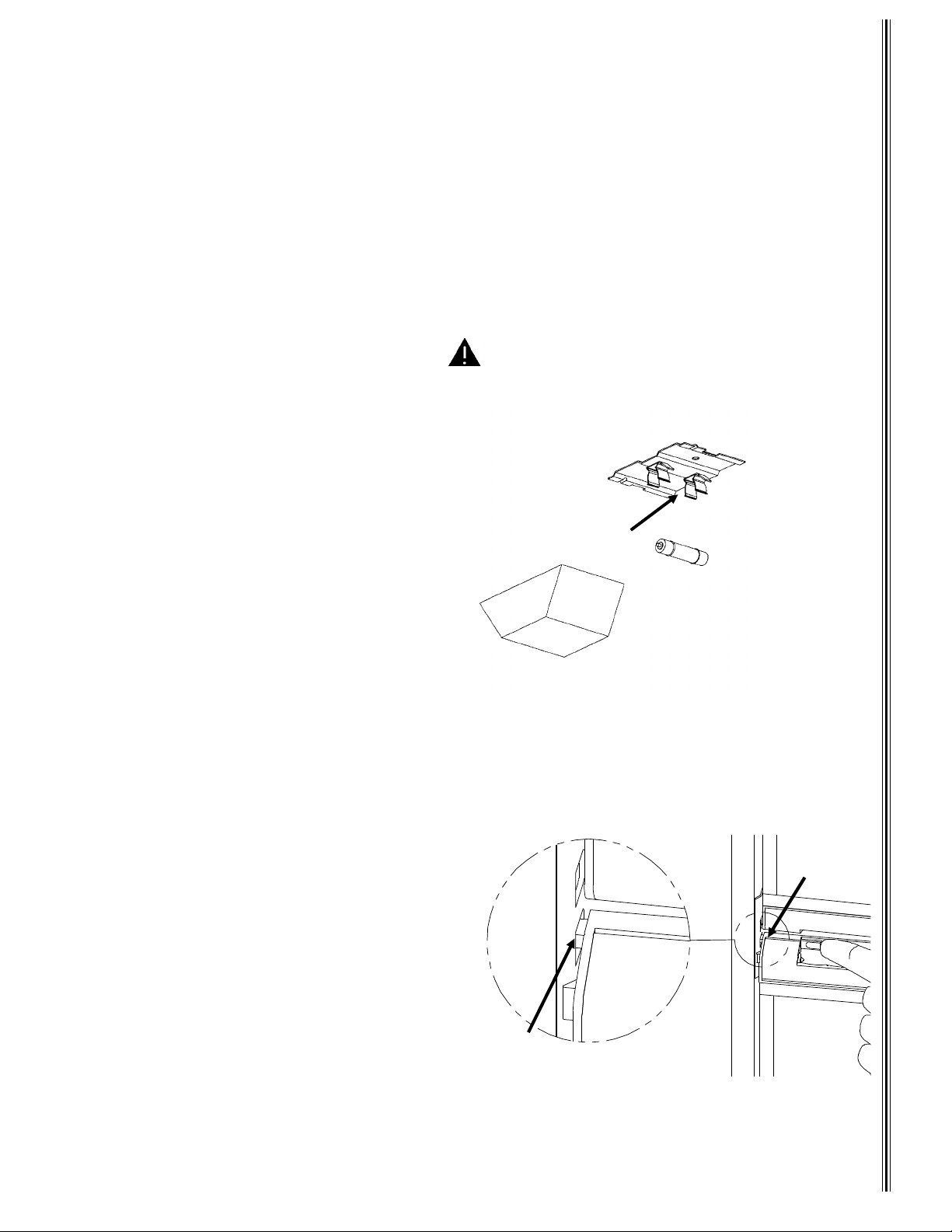
Crisper
g
y
y
g
g
g
y
g
)
g
g
y
g
(
)
g
g
y
g
g
g
g
g
The crisper in the bottom of the fresh food compartment, provides storage to preserve fruit and vegetable
freshness. Wrap ve
pushed in all the wa
etables with strong odors so the odor does not transmit to other foods. Keep the c risper
IMPORTANT!
.
The crisper is not dishwasher safe.
Door Storage
The door storage areas hold items such as 2 -li te r bott le s, h al f-gallon milk cartons, pop cans, ketsup bottles,
and other commonl
used items.
Moisture Reduction Heater
This refrigerator has a heater to prevent moisture from forming on the center divider between the freezer and
Li
Off
Li
ht Bulb
.
ht Bracket
fresh food compartment doors. The heater starts and stops when the refri
Cau tion: D o not replace with a higher wattage
Interior Light
The interior light is at the top of the fresh food
compartment. The li
when the refri
turns on when the fresh food compartment door
opens and off when the door closes. If the fresh
food compartment door sta
2 minutes, the li
for a click
To replace the light bulb
Disconnect the 12 VDC from the rear of the
refri
erator.
Slide the li
food compartment and pull it awa
bracket.
Remove the bulb from the li
Replace the bulb with a GE #214-2 bulb
only
this replacement bulb which can be pur-
chased from most retail automotive centers
Re-install li
erator is turned on or off. The light
to reset the controls and light.
ht cover toward the front of the fresh
ht cover and reconnect 12 VDC.
ht activates or deactivates
s open for more than
ht turns off. Close the door (listen
:
from the light
ht bracket.
use
.
Figure 1
bulb. Higher wattage bulbs can damage the interior surface of the fresh food compartment.
Bulb Holder
erator is turned On and
Li
ht Cover
About Your Refrigerator
Door Handle
The refrigerator door handles use a latch to insure complete door closure. The handle has a
e latch to enable the doors to be left partiall
stora
open to prevent odor build-up during extended
shut-down periods.
Figure 2
Stora
e Latch
Improtant! Do not use storage latch as a travel
latch. Storage latch allows doors to remain
partially open.
To use the storage latch, open the door about 1/2
inch and slide the stora
the strike plate.
e latc h in to th e c u t-o ut on
Strike Plate
Cut-Out
5
Page 6
y
g
g
g
y
y
g
g
g
g
g
y
g
g
y
Figure 3
g
)
y
To open the door, rotate the handle awa
from the refrigerator.
When closin
a click is heard, meanin
latched.
, push the door closed until
the door is
Figure 5
About Your Refrigerator
Shelf Retainer
Strip
Figure 4
Pull paper awa
from refrigerator
Strip of paper
Mountin
Screws (3
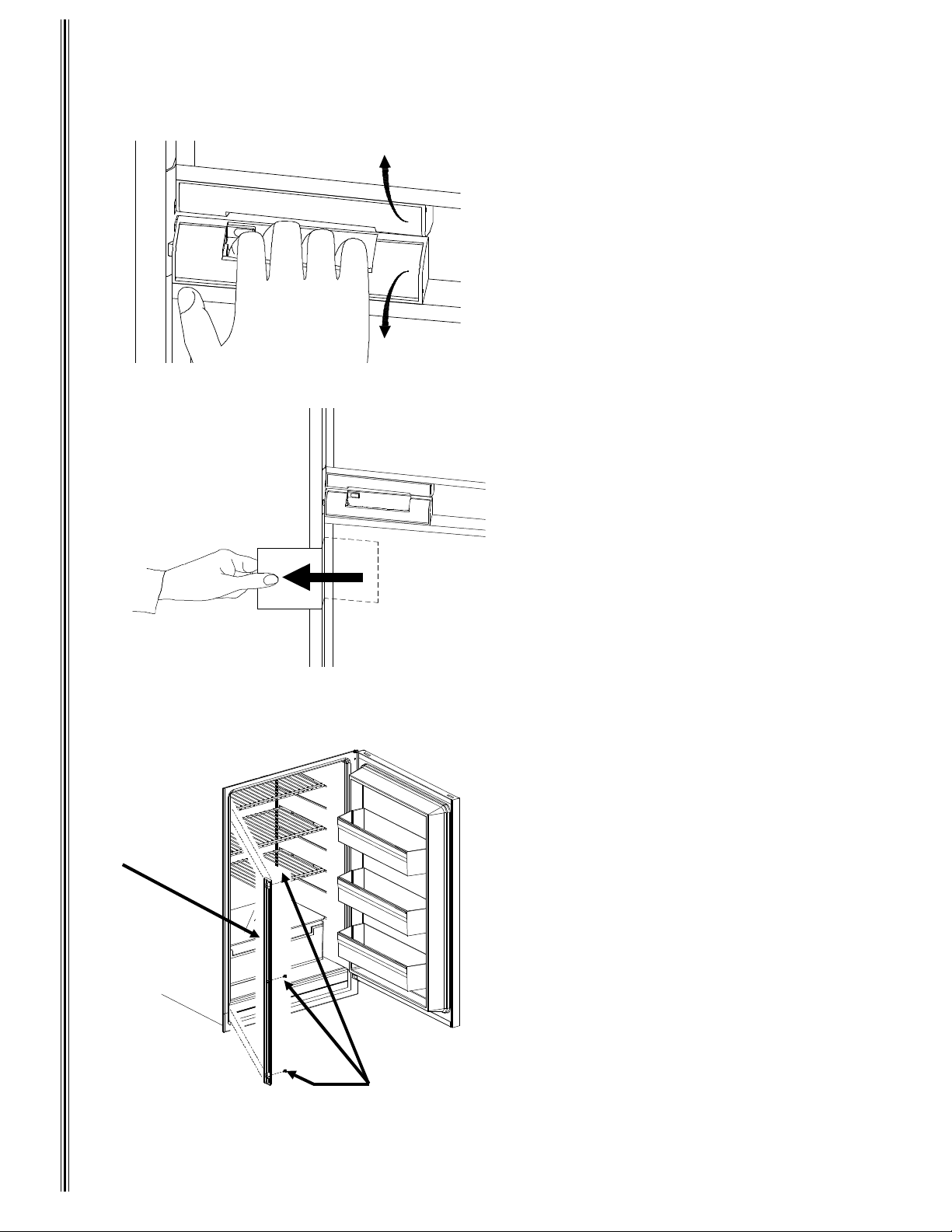
Checking Door Seals
To insure cooling efficiency and to prevent frost formation, the door
must seal completel
To check for proper door seal, la
strip of paper between the
the refri
out the paper. A d ra
Repeat all around the door. If the paper
does not have a noticeable dra
asket is not sealing. Contact your
dealer or a Norcold service center to
correct this.
erator. Close the door and pull
.
should be noticed.
askets
a
asket and
, the
Adjustable Shelves
Multiple shelf grooves in the freezer and
fresh food compartments allow
move the shelves for cleanin
ran
e the shelves to fit your needs. To
move the shelf in the freezer, pull the shelf
forward, select the new location, and slide
the shelf into place.
To move the shelves in the fresh food
compartment; use a Phillips screwdriver, remove 3 screws from the shelf
retainer strip. Lift and pull the retainer
strip awa
shelves forward to remove, select the
new location, then slide the shelf into
place. Reinstall the retainer strip and sec
To prevent child entrapment and shelf
u
movement, insure the shelf retainer is
r
reinstalled.
e
w
from the refrigerator. Pu ll the
ou to re-
and to ar-
6
Page 7
ith the 3 screws.
y
g
(
y
(E)
(C)
y
(
g
g
y
y
y
y
y
y
g
q
(
g
g
g
g
y
g
Figure 6
A
B
C
DE
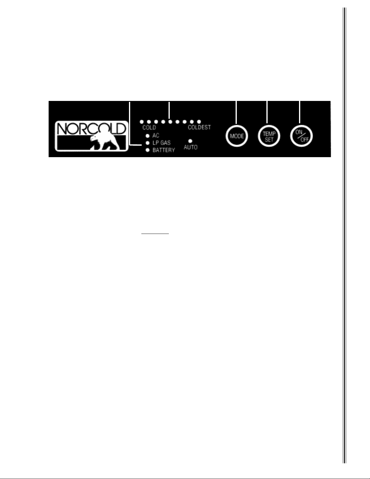
Refrigerator Controls and Operating Instructions
A 12 VDC supply is required to maintain the refrigerator’s operating control functions. The refrigerator receives its D C
power from the vehicle’ s 12 volt s
supplies power to the refri
The control panel
functionalit
ON/OFF
AUTO. If the unit is On, press this for
Press and hold
BATTERY-3 wa
TEMP SET
Press and hold
indicates the temperature, with COLD on the left and COLDEST on the ri
10 seconds. Quickl
Auto Mode
When AUTO mode is selected, the control automaticall
•
When 120 VAC is available, the AUTO and AC LE Ds light, meaning the refrigerator is operating on AC. After
10 seconds, the AC LED turns off and onl
the operating mode.
•
If 120 VAC is not available, the refrigerator switches to gas operation. The AUTO and LP GAS LEDs light. After
10 seconds, the LP GAS LED turns off and onl
displa
•
If 120 VAC or LP gas is not available, the refrigerator switches to DC (3-Way models only). The AUTO and
BATTERY LEDs li
and
operation.
modes are unavailable
Durin
the current energy source and switch to the higher priority energy source. If AC becomes available while the
erator is in AUTO LP GAS mode, the refrigerator switches to AUTO AC operation.
refri
If an operatin
source. If a lower energy priority source is not avai lable, the LED co ntinues to fl ash, and the refr igerator stops oper atin
until the energy source is corrected. See
. The AC, LP GAS, Battery, and AUTO LED’s (A) light indicating the operating mode.
turns the refrigerator On or Off. If the refrigerator is Off, press this to turn it On and set the mode to
MODE
models only). The refrigerator does not switch to the new mode until you release
thermostat) (D) sets the refrigerator and freezer temperatures in both gas and electric operation.
TEMP SET
the operating mode.
uickly release
DC electric should not be used to initially cool the refrigerator
operation in AUTO mode, if a higher priority energy source becomes available, the contr ols stop usin
mode is not fun cti on al , its L E D f la she s an d t he ref r igerator tries to operate in a lower energy priorit
erator and to other DC components in the vehicle.
between the freezer and fresh food compartments), conveniently locates all refrigerator
press and release TEMP SET to display the temperature setting.
ht. After 10 seconds, the BATTERY LE D turns off and only the AUTO LED stays lit. Press
MODE
stem; either an auxiliary battery, a converter, or the engine battery. The 12 VDC system
2 seconds
to cycle through the choices; one AUTO and three manual modes (AC, LP GAS, or
to select the temperature. The temperature settin
to display the operating mode. DC operation is not as efficient as LP Gas or AC
for example; while in transit).
Diagnostics
to turn the refrigerator Off.
s are LEDs (B). The lighted LED
ht. The temperature LED turns off after
selects the energy source using this scheme:
the AUTO LED stays lit. Press and quickly release
the AUTO LED stays lit. Press and quickly release
. Only use DC when the other
for corrective actions.
MODE
MODE
.
to displa
MODE
to
Operating Controls
7
Page 8
Manual Mode
g
g
g
y
g
g
g
g
y
g Sy
)
g
g
j
j
g
g)
g
y
y
g
g
)
(
)
(
)
g
y
y
g
y
(
)
g
g
y
(
)
g
g
)
g
)
g
y(s)
y
g
y
(
)
y
g
(
)
g Sy
y
g Sy
Press and hold
the operatin
mode, the correspondin
MODE
until the AUTO LED
mode LED stays lit until an alternate mode is selected. If the energy source is interrupted in MANUAL
LED flashes, and the refrigerator stops operating until an alternate energy source is
selected or the problem is corrected. See
oes out and the desired operating mode lights. Unlike AUTO mode,
Diagnostics
for corrective actions.
AUTO and MANUAL Modes - Gas Operation Onl
If gas does not ignite within 30 seconds, the refrigerator’s gas valve automatically closes and the operatin
controls select an alternate energy source (AUTO Mode) or revert to a stand-by mode where the LP GAS LED
flashes. The LED flashes until the refri
attempts, check input
operatin
ou release
mode by pressing and holding
MODE
Backup Operatin
as supply, or consult your dealer or a Norcold authorized service center. Select a different
.
stem (BOS
erator is turned OFF and then ON. If gas does not ignite after several
MODE
. The refrigerator does not switch to the new operating mode until
This refrigerator has a Back-Up Operating System to allow the refrigerator to cool in case of a failure within the
temperature sensin
This mode provides coolin
About Your RefrigeratorDiagnostics
this mode. If the temperature is too cold, ad
is too warm, ad
for one hour before rechecking the temperatures (frequent door opening prevents the temperatures from
settin
stabilizin
. While the refrigerator can operate in this mode, Norcold recommends that you seek service as soon
circuit. If this happens, the TEMP SET LED flashes and refrigerator switches to BOS mode.
until the refrigerator is serviced. Check refrigerator temperatures when operating in
ust the thermostat to the left in single LED steps. If the temperature
ust the thermostat to the right in single LED steps. Allow the refrigerator to operate at the new
as practical to restore normal operation.
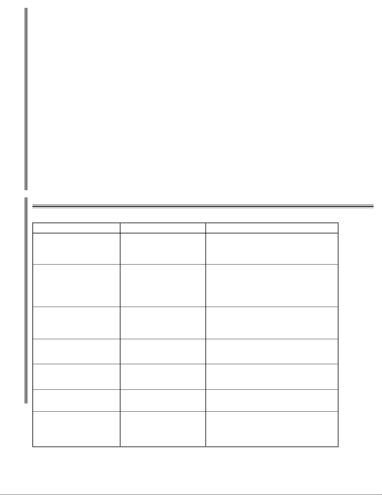
Diagnostics
When : IT Means: You Need to Check:
No LED"s li
ht Control voltage is unavailable to
Flashing LP GAS LED
flash, pause, flash, pause etc.
Flashing AC LED
flash, pause, flash, pause, etc.
Flashing AC LED
flash, flash, pause, flash, flash,
pause, etc.
Flashing BATTERY LED (flash,
flash, pause, flash, flash, pause,
etc.
Flashing BATTERY LED
flash, flash, flash, pause, flash,
flash, flash, pause, etc.
Current TEMP SET LED flashin
flash, pause, flash, pause, etc.
displa
panel
LP gas ignition fault
Initial start-up
Fault external to refrigerator
controls
AC Mode selected but AC
power not available
Fault external to refrigerator controls
AC input volta
Fault external to refrigerator controls
DC input volta
e too low or too high
e too high or too low
Fault within refrigerator controls
Fault within refrigerator controls
Back-Up Operatin
stem
Mode
10.5 to 15.4 VDC supplied to refrigerator.
Batter
charging equipment or converter.
DC connection to the refri
erator’s DC fuse (3 Amp - Control Fuse
Refri
See your dealer or a Norcold Service Center
10.5 to 15.4 VDC supplied to refrigerator.
as lines been purged?
Have
LP tank valve on?
LP tanks empt
LP suppl
Refri
erator’s manual shut-off valve open.
See
our dealer or a Norcold Service Center
Is refrigerator plugged into a functional AC outlet? Has
the vehicle fuse or circuit breaker blown?
Vehicle
erator’s AC fuse (5 amp) blown?
Refri
See
our dealer or a Norcold Service Center
AC input to refri
If AC problem cannot be located, see your
dealer, campService Center
Batter
Batter
DC connection to the refri
our dealer or a Norcold Service Center
See
See
Temporar
Operatin
See your dealer or a Norcold Servic e Cen te r
?
pressure 11" water column.
enerator functioning (if applicable).
erator (108 VAC to 132 VAC
round administrator, or a Norcold
Voltage
charging equipment or converter
Not owner serviceable
our dealer or a Norcold Servic e Cen te r
Not owner serviceable
operating mode; read Back-Up
erator.
erator
;
;
stem. Seek service as soon as
practical.
8
Page 9
Page 10

7. Inspect the flue of refrigerator’s cooling system. This area must be free of foreign materials. Foreign materials observed
in the flue indicate the burner requires cleaning.
8. Insure the area directly behind the refrigerator is not being used for storage. Keep the refrigera tor area clear and free from
combustible materials, gasoline, and other flammable vapors and liquids.
9. Periodically inspect the ventilation system. The air passage from t h e bo t t o m in t a k e v e nt t o r e f r ig e r a t o r c o il s a n d f r om t h e
refrigerator coils through the upper exhaust vent must be unobstructed.
10. Inspect combustion seals (visual check without removing the refrigerator). Combustion seals are
attached to the back surfaces of the refrigerator’s mounting flanges and must be continuous between the wall and the
mounting flanges.
11. Periodically inspect door seals.
Refrigerator Storage
When the refrigerator will not be in use for an extended (seasonal) period of time, it is recommended that all power to the
refrigerator be disconnected. Unplug the refrigerator’s AC power cord from the wall receptacle and disconnect the 12 volt
DC supply wires from the refrigerator’s power board located at the rear of the refrigerator. Clean the re frigerator interior a nd
latch the doors in the storage po sition. After the extended shut-down period, the burner, burner orifice, and flue must be
inspected before igniting the burner flame. These areas must be free from dust, spider webs, or other obstructions which might
restrict t he combustion system.
Refrigerator Removal and Replacement
To remove th e re fri gerat or, di sco nnec t bo th A C a nd D C p ower sour ces from the refr igera tor. Turn o ff th e pr opan e gas at
the main supply tank. Turn the refrigerator’s manual shut-off valve. Disconnect the gas supply piping at the manual shut-off
valve. Remove the mounting screws securing the refrigerator to the enclosure. Remove refrigerator from the enclosure.
Before reinstalling the refrigerator, inspect the areas be hi nd the mounting fla nges fo r d ama ged or mis sing seal strips.
These seal strips serve as a combustion seal which isolates the living space of the vehicle from refrigerator’s combustion system.
Reinstall the refrigerator by reversing the above procedures. After reinstalling the refrigerator, check the ga s fi tt ing connections for
Do not check for leaks with an open flame. Use an approved leak-detection solution
leaks.
.
Ignition/Sense
Burner Flame Inspection
Maintenance
The efficiency of your refrigerator while operating in the
gas mode is depe ndent up on the corr ect burn er flame . The
burn er flam e p rovides energy to the refrigerat or’s cooling
system.
The burner flame effici ency is a function of corre ct input
gas supply pressure, air input, and burner and burner
orifice cleanliness.
A visual check of the burner flame should be made
regularly. The flame should be sharp blue with a stable
burning appearance (Figure 11). If there is a constant
yellow component observed or if the flame appears erratic or unstable, switch the refrigerator to electr ic or turn the refrigerator
"OFF" and contact a qualified installer, service agency, or gas supplier.
Electrode
Burner
Flue Tube
Pale Blue
Outer Cone
Sharp Blue
Inner Cone
Procedure for Cleaning the Cooling System Flue
WARNING
Carbon Monoxide if the refrigerator’s burner, burner orific e, and the flue tube are not r egularly cleaned.
To prevent Carbon Monoxide, the burner, burner orific e, and the cooling system’s flue tube must be
cleaned at least once a year and after
cleaning procedures, or contact a qualified installer, your dealer or a Norcold service center.
Car bon Monoxide can be hazardous to your health. Gas appliances may emit excessive
all prolonged (seasonal) shut-down periods. Refer to the following
Figure 11
10
Page 11
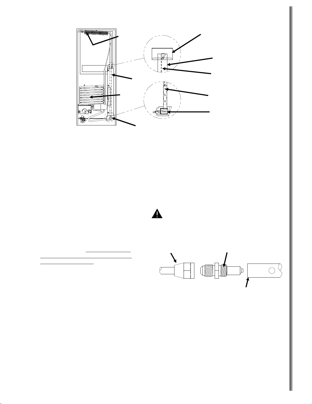
Condenser
Flue
Absorber
Coils
Heat Deflector Cap
Flue Tube
Spiral Flue Baffle
Suspension Wire
Spiral Flue Baffle
Figure 12
Burner Assembly
Burner Box
1. Remove the refrigerator from its enclosure. Follow "Refrigerator Removal and Replacement"
procedure beginning on page 11.
2. Remove the heat deflector cap from th e flu e.
3. Remove the spiral flue baffle from the flue tube.
4. Using a stiff brush or fine emery cloth, clean the spiral flue baffle of debris.
5. Clean the inside of the flue tube with a flu e brush. Inspect burner after cleaning.
6. Re-install the spiral flue baffle. Insure the spiral flue baffle is securely in place. The spiral flue
baffle is required for efficient cooling while operating in the gas mode.
Burner Orifice Removal and Cleaning
1. Turn off the gas at the main tank.
2. Turn the refrigerator off.
3. Remove the screws securing the burner
cover and burner box to the refrigerator.
4. Loosen the flare nut and remove the burner
tube from the orifice.
to the gas line, use two wrenches when
loosening the flare nut.
5. Carefully remove the gas tube from the
burner.
6. Remove the orifice and clean with alcohol and
air pressure.
7. Remove the screw securing the burner to the
burner bracket. Remove the burner.
8. Use air pressure to remove dust, spider webs, etc., from inside the burner. Clean the ports of the burner
with a brush.
9. Clean and inspect the ignition/sense electrode. Replace if corroded, cracked, or broken.
10. Using air pressure, clean any debris from burner bracket of cooling system.
11.Thread orifice into the burner until finger tight. Tighten 1/4 turn with wrench. Thread flare nut to orifice. Do
not cross-thread connections. To prev ent da mage, use tw o w r enche s w hen ti g htening.
12. Leak test all fittings using a soapy water solution.
monia
open flame
will attack brass fittings of the burner and gas valve assemblies. Do not leak test fittings with an
.
To prevent damage
Caution: Do not clean the orifice with a pin, drill
or similar object.
Flare Nut
(On Gas Tube)
Orifice
Burner
Figure 13
Do not use a solution which contains ammonia. Am-
Body
Maintenance
11
Page 12
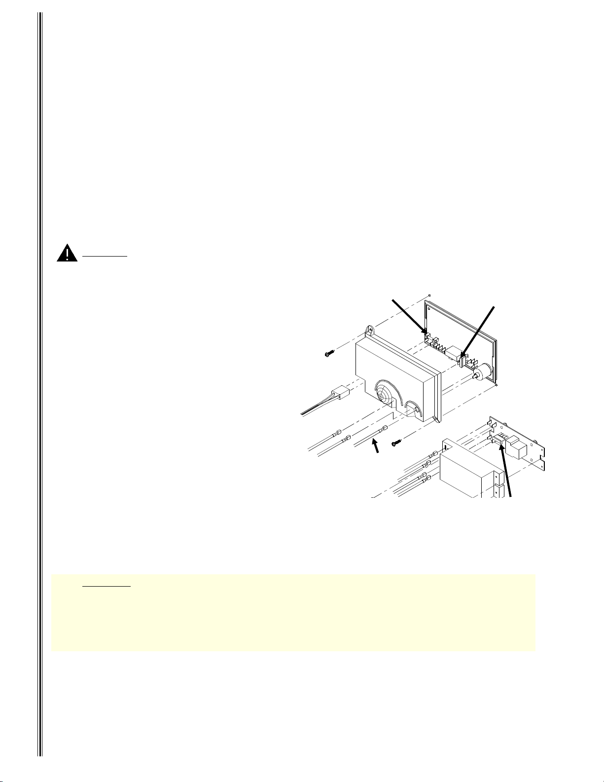
Fuse Replacement Procedure
The refrigerator’s electrical circuits are fused to protect them from a circuit overload. If the "Diagnostic Codes and Their
Meaning" section indicates that the refrigerator fuse is blown, follow the replacement procedures below.
1. Turn the refrigerator to "OFF".
2. Disconnect the AC power cord from the
wall receptacle.
3. Disconnect the AC power cord from the
power board cover at the rear of the refrigerator
from the power board cover.
4. Disconnect the 12 volt DC supply wires from
the power board cover (A).
5. Remove the ignition wire/sense wire from the
power board cover.
CAUTION . Failure to follow this procedure can lead to personal injury or property damage.
6. Remove the three screws which secure the
power board cover t o the refri gerat or, pull
cover away.
Do not operate refrigerator
without power board cover.
7. For 3-Way models, disconnect the supply
Mounting Screw
wires from the extention board (B) as shown
in Figure 8.
Note! Remember how the wires were removed.
Reattach wires to the same location as they
AC Supply
Cord
were when removed.
1. Blue wire from power board connects to terminal #7 of extention board.
Maintenance
2. Red wire from power board connects to terminal #9 of extention board.
3. Black wire connected to refrigerator chassis
12 VDC Supply
Wires
+
Grd.
connects to terminal #8 of extention board.
4. Yellow wire of the DC heater connects to terminal #6 of the extention board.
8. Remove the two screws which secures the ex-
Figure 8
tention board cover (B) to the refrigerator. Pull
cover away from the refrigerator. Do not operate refrigerator without cover.
9.. Replace blown fuse with the specified fuse listed in the WARNING above.
5 Amp Glass Cartridge
AC Fuse
Ignition/Sense
Wire
2
3
4
3 Amp Blade-Type Fuse
(Control Fuse)
1
20 Amp Blade-Type
Fuse (3-Way
Models Only)
WARNING A circuit overload can result in an electrical fire when incorrectly sized fuses are used.
To prevent a possible electrical fire, follow the fuse specifications given below:
DC Control Circuit - 3 amp (purple) blade-type automotive
DC Heater Circuit - 20 amp (yellow) blade-type automotive
AC Circuit - 5 amp glass cartridge
10. If a fuse continues to blow, contact your dealer or a Norcold Service Center for corrective action.
12
Page 13
Failure of refrigeration does not necessarily mean the cooling system is defective. Check other factors governin
g
g
g
(
)
g
g
g
g
g
its operation.
If a dia
If the refri
operation
If the refri
After the refri
refri
the cooling fault. If no cooling is evident after eight hours (or overnight), the cause of failure may be the coolin
unit. To determine the actual cause for failure, contact your dealer or a Norcold service center
nostic indicator appears, see
erator is operating on gas and a loss of cooling is noticed, switch the refrigerator to AC mode of
Start-Up Instructions
see
erator has been operating on electric, switch to gas operation.
erator has been switched from one power source to the other allow several hours to assure the
erator is cycling properly. This will determine if a component failure in the electric or gas controls is causin
Diagnostics
.
.
No Refrigeration
13
Page 14
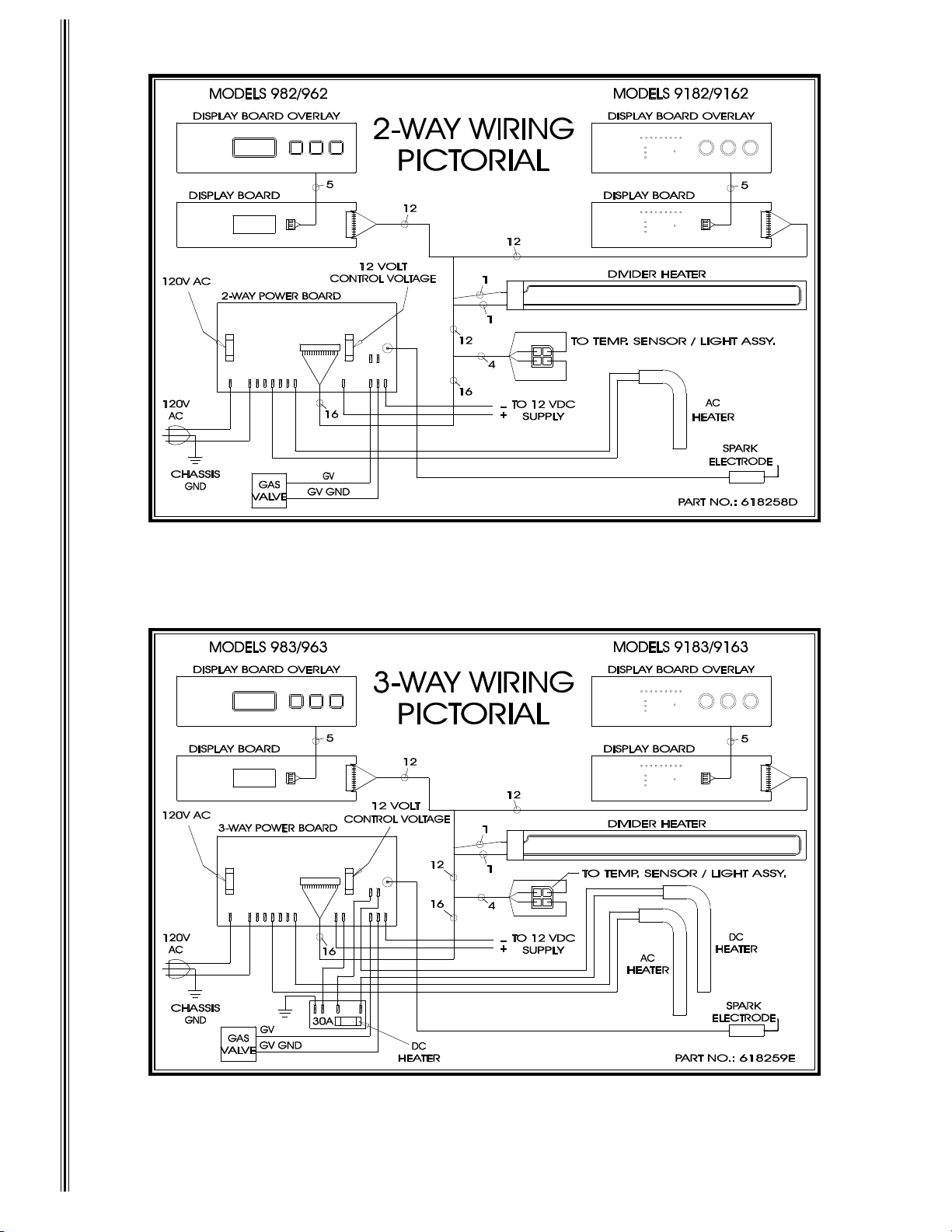
Wiring Pictorials
14
Page 15
LIMITED TWO YEAR WARRANTY
g
y
y
y
y
y
y
y
y
g
y
g
g
y
y
y
y
(1)
(2)
(3)
y
(4)
y
(5)
(6)
(7)
(8)
y
y
y
y
g
y
y
y
(1)
(2)
y
This Limited Warranty is given by NORCOLD (Company) to the original consumer-purchaser of any new refrigeratin
equipment (Equipment) supplied by the Company, excluding glassware, electric light bulbs, replaceable fuses, and will
be effective for a period of two
shall at all times have been in possession of and used b
The Company will provide free service and replacement of defective parts at no charge at all authorized
A.
Norcold Service Centers for a period of two
Warrant
covers labor costs incurred in removing and re-installing the refrigerator only when necessary to
replace a defective part. The Compan
defective part, for a two-year period commencing with date of purchase. The original consumer-purchaser
must pa
An
ori
The following procedure shall be followed by an original consumer-purchaser desiring to obtain
all expenses incurred in making the equipment availa ble at one of the Norc old Service Centers .
parts replaced under warranty (including cooling units) will be warranted for the duration of the
inal warranty period.
B.
performance under the terms of this Limited Warrant
Norcold Service Centers and the ori
ori
inal consumer-purchaser: and (2) that the item claimed to be defective is still within the warrant
coverage. If the original consumer-purchaser is unable to accomplish this task, written notice should be
immediatel
directed to Norcold an d advice will be promptly given concerning the manner in which warrant
service may be obtained. Inability to physically bring the refrigerator to a Norcold Service Center will not void
the warrant
, but any additional costs thereby incurred are solely for the account of the original
consumer-purchaser.
The Company will not be liable under this Limited Warranty for any of the following:
C.
Travel expenses for warranty coverage.
Defects which arise by reason of transit damage, misuse, neglect, or accident.
Manufacturing defects found at the time of purchase, parts replaced under warranty, and associated
labor, which are not communicated to the Compan
chaser.
Labor performed without need for parts replacements which is not communicated to the Compan
within 30 days by the original consumer-purchaser.
Defects in glassware, electric light bulbs, or replacement of fuses.
Defects arising from improper installation, maintenance, or adjustment of the Equipment.
The need for normal maintenance of this refrigerator according to the guidelines specified in the
Operator’s and Installation Guides.
Defects arising from the improper use of parts or parts not manufactured or supplied by the Compan
in the course of repairs or replacements to the Equipment.
Employees and agents of the Company, and its authorized service representatives, have no authorit
D.
to vary the terms of the Limited Warranty, which applies only to Equipment purchased and installed in
the United States of America and the Dominion of Canada. The Compan
an
improvements or changes in parts or models without notice to any original consumer-purchaser.
The Company shall not be liable or in any way responsible for any loss or damage to person or property,
E.
or lost profits or other similar loss or dama
in an
parts of the Equipment covered by this Limited Warranty. Some states do not allow the exclusion
or limitations of an
appl
to you.
Any implied warranty of merchantability or fitness for a particular purpose:
F.
Applicable to a part or parts of the refrigerator is limited to a period of two years from date of purchase.
Some states do not allow limitations on how long an implied warranty lasts. The above limitations
ma
not apply.
This Warranty gives you specific legal rights. You may also have other rights which vary from state to
G.
state.
ears from date of original purchase. The Company warrants, provided that the Equipment
the original consumer-purchaser, that:
ears from the date of original purchase. This Limited
will pay normal inbound and outbound transportat i on costs of an
. The refrigerator must be brought to any of the
inal consumer-purchaser must present evidence (1) to identify the
within 30 days by the original consumer-pur-
reserves the right to make
e that may result or be claimed to have resulted from a defect
incidental or consequential damages, so the above limitation or exclusion may not
15
 Loading...