


Norcold 462, 482, 442, 453, 452 User Manual
...
INSTALLATION AND OPERATING
INSTRUCTIONS
442 443 452 453
482 483 462 463
WARNING
Improper installation, adjustment, alteration, service, or maintenance can cause injury or property damage. Refer to this manual. For assistance or additional information consult a qualified installer, service agency, or the gas supplier.
FOR YOUR SAFETY
Do not store or use gasoline or other flammable vapors and liquid in the vicinity of this or any other appliance.
FOR YOUR SAFETY If you smell gas:
1.Open windows
2.Do not touch any electrical switches
3.Extinguish any open flame
4.Immediately call your gas supplier
Contents |
|
Safety Precautions .............................................. |
2 |
Extended Service Protection Plan ...................... |
4 |
Ventilation Requirements .................................... |
5 |
Installation Instructions........................................ |
8 |
Decorative Door Panel Installation.................... |
11 |
Reversing Door Swing ...................................... |
11 |
Lighting and Start-Up Instructions..................... |
14 |
Operating and User Instructions ....................... |
15 |
Refrigerator Maintenance.................................. |
17 |
Trouble Shooting................................................ |
19 |
Failure of Refrigerator ....................................... |
20 |
Replacement Parts............................................ |
20 |
Wiring Diagrams................................................ |
21 |
Warranty ............................................................ |
23 |
These refrigerators are designed to operate on the following energy sources:
LP GAS OPERATION - 11.0 inches Propane & 12 volt DC control voltage (15.4 volts max., 10.5 volts min.). AC OPERATION - 120 volts AC (132 volts max., 108 volts min.) and 12 volt DC control voltage.
DC OPERATION - [3-WAY MODELS] 12 volts DC (15.4 volts max., 11.5 volts min.). Operation where these specifications are exceeded will void the refrigerator warranty.
MODEL NO. ______________________________ SERIAL NO. ______________________________
The refrigerator’s model number and serial number are on the serial plate located in the refrigerator.
Part No.: 618484B (95-09)
Safety Precautions
Read this manual and become thoroughly acquainted with it before installing or starting the refrigerator. The following safety precautions and recommendations contained herein are for your protection.
Improper installation, adjustment, or operation can cause injury or property damage.
The safety symbols used in this manual contain Safety Alert information. Understand their meanings and be safety conscious.
DANGER
 WARNING
CAUTION
General
A SITUATION WHICH, IF NOT AVOIDED, WILL RESULT IN DEATH OR SERIOUS INJURY.
A SITUATION WHICH, IF NOT AVOIDED, COULD RESULT IN DEATH OR SERIOUS INJURY.
A SITUATION WHICH, IF NOT AVOIDED, MAY RESULT IN MINOR OR MODERATE INJURY.
∙Keep the unit and surrounding area clean. Never use the area behind refrigerator for storage; in particular, storing flammable materials (oily rags, paper, aerosol cans, and chemicals.). Stored materials not only present a safety hazard but could block the ventilation to the system.
∙Provide appropriate fire extinguishers installed in convenient locations. Consult your local fire department for the correct type to use. Do not use foam on electrical fires. Use extinguisher rated by NFPA.
∙Make sure all fasteners, supports, seals, electrical covers are secure.
LP Gas System
∙LP gas is highly flammable. Gas connections must be leak tight. Do not smoke, create sparks or use an open flame when checking gas connections. Do not ignore the "rotten egg" smell of gas fumes.
∙Protect all gas lines from physical damage, vibration, or excessive heat.
∙Insure that the supply gas pressure is within the tolerance specified on the front cover of this manual. The gas controls are designed for safety. Never tamper with the adjustment or function of the controls other than as directed by the Lighting and Shutdown Instructions. All repairs must be done by a qualified service person.
Exhaust Gases
∙Proper ventilation to remove exhaust gases is extremely important. These gases, generated in the GAS mode at the rear of the refrigerator, replace the oxygen in the air and in extreme cases can produce dangerous levels of carbon monoxide. This manual contains installation instructions to safely remove the exhaust gases and seal the zone from the living area. The installation instructions are certified by American Gas Association and Canadian Gas Association and must be followed.
∙Check the burner for proper flame characteristics at the initial start-up and at least once every year. The information for this check is located in this manual and must be performed by a qualified service person.
2

Safety Precautions - continued
Electrical Circuits - AC and DC
∙The 120 volt AC circuit must be properly grounded. Never cut or remove the round grounding prong from the refrigerator’s AC cord. Do not use a two-prong adapter. Do not use an extension cord to connect to the approved AC receptacle.
∙Protect all wiring from physical damage, vibration, or excessive heat.
∙Always disconnect both AC and DC sources of power when working on either circuit (only a qualified service person).
∙Insure all terminating connections are clean and tight to prevent arcing or overheating.
∙Never allow Leak Detecting fluids or any other liquids to spill on electrical connections. Many liquids are electrically conductive and could cause serious arcing damage and, in some case, fires.
Refrigerant System
∙Never physically bend, drop, drill, weld, or hammer the refrigerant system. Doing so could cause the system to rupture and release dangerous chemicals which can cause severe burns to the eyes or skin. If ignited, these chemicals will burn with intense flame. A leaking system can release certain chromium components which, if inhaled, can cause cancer.
∙Never apply direct heat in excess of 240° F to the refrigerant system. Because the refrigerant is hermetically sealed under pressure, a temperature sensitive safety device opens to protect the system from erupting under excessive pressure. However, the expelled refrigerant could ignite and burn if an ignition source were near.
∙Never attempt to repair or recharge the refrigerant system. If defective, it must be replaced.
Child Entrapment
∙Never install door locks or other restraints which could entrap small children within the refrigerator. The Travel Latch system must not be modified.
Handling the Refrigerator
∙Never lift the refrigerator without assistance. Protect yourself from body strain.
∙Avoid hot surfaces at the rear of the refrigerator when operating. The absorption type refrigerator produces several hot areas at the rear of the unit. This is true whether in GAS or ELECTRIC mode.
∙Take care to avoid brushing against the irregular shapes and sheet metal parts at the rear of the refrigerator. Cuts or abrasions could result.
3
E.S.P.
EXTENDED COOLING UNIT SERVICE PROTECTION PLAN
An additional four year Service Contract is now available to original purchasers of Norcold refrigerators. For only $40.00 you get:
*Four extra years protection against cooling unit failure.
*Automatic replacement of defective cooling unit.
*Pre-paid freight from your dealer to Norcold and return.
*Labor free of charge.
The E.S.P. (Extended Service Protection) plan can be obtained by mailing your check for $40.00*, U.S. funds to:
NORCOLD
P O BOX 4248
SIDNEY OH 45365-4248
If mailing in Canada:
GREG LUND PRODUCTS LTD P O BOX 760
OAKVILLE ONTARIO CANADA L6J 5C4 E.S.P. is a service contract between Norcold and
the original purchaser. The contract provides replacement of a defective cooling unit only for this refrigerator (freight, parts, and labor) for an additional period of four years after expiration of the original Limited Warranty. The refrigerator must be delivered to Norcold Service Center together with the Norcold E.S.P. card showing E.S.P. coverage. An E.S.P. card will be mailed to the original purchaser upon receipt of a completed Service Contract Application form and a check covering the E.S.P. charge. E.S.P. coverage is non-transfer- able and non-refundable.
To register your refrigerator, fill out the warranty Service Contract Application - i.e.: Tear Sheet Form in yellow envelope or include the following information (Please Print Clearly):
1.Owner’s name and address.
2.Refrigerator model number.
3.Refrigerator serial number.
4.Date of purchase.
5.Refrigerator proof of purchase
6.Check for $40.00* (payable to Norcold).
Applications will be accepted only if they are mailed within ninety (90) days after date of purchase.
*Ohio residents, add $2.60 sales tax.
General Instructions - All Models
The refrigerators described in this manual are designed for built-in installations and require cut out dimensions as indicated on page .
The refrigerators must be placed on a solid and level floor away from heat generating sources. The floor must be strong enough to support the combined weight of the refrigerator and its food load.
Never install the refrigerator directly on carpeting. To protect carpeting, the refrigerator must be placed on a metal or wood panel extending at least the full width and depth of the refrigerator.
Keep the refrigerator and the surrounding area clear and free of combustible materials, gasoline, and other flammable materials.
Note: These appliances are not approved for use as a Free-Standing refrigerator. The refrigerator must be used in the manner for which it was designed. Refer to this manual for installation, operating procedures, and the refrigerator intended use. This appliance is equipped for LP gas and cannot be converted to any other fuels (Natural Gas, Butane, etc.).
4

VENTILATION REQUIREMENTS
WARNING: Carbon Monoxide can cause nausea, fainting, or death. Inadequate ventilation or partial blockage of the refrigerator’s flue can result in increased carbon monoxide emissions when operating in the gas mode. To prevent the emission of levels of carbon monoxide, installation must assure complete isolation of the living space of the R.V. from the refrigerator’s combustion system. Follow Norcold’s Ventilation and Installation recommendations explicity.
Venting is required in an R.V. refrigerator installation to remove the products of combustion, to isolate the living space of the vehicle from the combustion system of the refrigerator, to remove the excess heat from the generator area of the refrigerator’s cooling system, and to remove the heat that is extracted from the refrigerator cabinet.
Certified installation requires that one intake (lower) and one exhaust (upper) be used. For the models 6052, 6053, 652, and 653, the installer has the option of exhausting through the roof or through an upper side wall vent. Whether roof or side wall exhaust venting, the specified vent kit must be installed as directed by this manual. To insure adequate refrigerator performance, a continuous air flow is required across the refrigerator’s cooling system.
The air passage from the intake vent to the refrigerator coils and from the refrigerator coils through the exhaust vent must be unobstructed.
TABLE 1
DIMENSIONS (INCHES) for Vent Kits 2, 3, and 4
The vents for these refrigerators are certified by A.G.A. and CGA and must be installed as directed by this manual without modification. Any deviation or substitution:
*Can result in carbon monoxide levels in the living space of the vehicle.
*Will void the agencies’ certification.
*Will void the refrigerator warranty.
*Will effect refrigerator performance.
The intake vent (lower) also serves as a access (service entrance) door. The bottom of the intake vent opening must be flush with the surface on which the refrigerator is mounted. This configuration allows any leaking propane to ventilate to the outside.
A.G.A. And CGA certification permits installing the refrigerator with zero (0) inches minimum clearance between the refrigerator and any adjacent walls. This certification does not specify any maximum clearance. However, to insure adequate air flow across the cooling system, the clearance must be minimized. The combination of the two vents and the minimum clearances provide the necessary air flow through the creation of a natural draft, or "chimney effect" across the cooling system.
Certified Vent Kits
Kit Number |
Certified Lower |
Certified |
Models |
|
Vent Door |
Roof Jack |
|||
|
|
|||
|
|
|
|
|
|
|
|
|
|
|
615998 |
|
|
|
2 & 3 |
616009 |
615791 |
All Models |
|
616010 |
||||
|
|
|
||
|
617778 |
|
|
|
|
|
|
|
|
|
|
|
|
|
|
|
|
|
|
|
Certified Lower |
Certified |
|
|
Kit Number |
Upper Side |
Models |
||
Vent Door |
||||
|
Exhaust |
|
||
|
|
|
||
|
|
|
|
|
|
615998 |
|
442. 443 |
|
4 |
616009 |
|
||
617485 |
452, 453 |
|||
616010 |
||||
|
|
ONLY |
||
|
617778 |
|
||
|
|
|
||
|
|
|
|
|
|
|
|
Cut - Out Dimension (inches) |
|
|
|||||
|
|
|
|
|
|
|
|
|
|
|
|
|
|
|
Roof Jack |
|
Lower Intake Vent |
|
Approved |
||||
|
|
|
|
|
|
|
|
|
|
|
Models |
|
Part No. |
Type |
Length |
|
Width |
Height |
|
Width |
|
Radius |
|
|
|
|
|
|
|||||||
|
|
|
|
|
|
|
|
|
|
|
|
|
617778 |
Plastic |
- - |
|
- - |
13 3/4 |
|
21 1/2 |
|
- - |
All Models |
|
|
|
|
|
|
|
|
|
|
|
|
|
616010 |
Sq. Corner |
- - |
|
- - |
13 3/4 |
|
21 3/4 |
|
- - |
All Models |
|
|
|
|
|
|
|
|
|
|
|
|
|
616009 |
Rad. corner |
- - |
|
- - |
13 3/4 |
|
21 7/8 |
|
3 1/4 |
All Models |
|
|
|
|
|
|
|
|
|
|
|
|
|
615998 |
Rad. Corner |
- - |
|
- - |
13 3/4 |
|
21 7/8 |
|
3 1/4 |
All Models |
85 |
|
Upper Side |
-- |
|
-- |
7 1/4 |
|
18 |
|
-- |
6052, 6053 |
|
|
vent |
|
|
|
|
|
|
|
|
652, 653 |
|
|
|
|
|
|
|
|
|
|
|
|
|
615791 |
Roof Jack |
24 |
|
5 1/4 |
- - |
|
- - |
|
- - |
All Models |
|
|
|
|
|
|
|
|
|
|
|
|
|
|
|
|
|
|
|
|
|
|
|
|
5
1 |
|
|
|
3 |
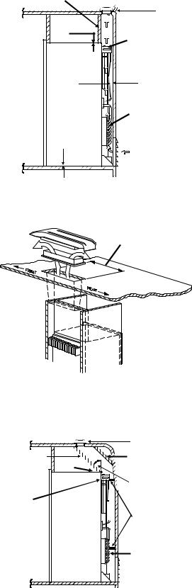
Optimum Installation - Figure 1 |
||
|
|||
2 |
The optimum installation is illustrated in Figure 1. |
||
Condenser |
|
|
|
(source of |
1. |
Area above refrigerator blocked (baffled) off to |
|
rejected heat) |
|||
|
|
prevent trapping of hot air above the refrigerator. |
|
4 |
2. |
0 -1/4 inch clearance at the top of the refrigerator. |
|
|
3. |
Exhaust vent centered directly over refrigera- |
|
Absorber |
|
tor’s condenser. |
|
4. |
0 - 1 inch at rear of the refrigerator. |
||
(source of |
5. |
0 inch clearance at bottom of refrigerator. |
|
rejected heat) |
|||
|
|
||
5 |
|
|
|
Air flow path |
|
|
|
Figure 1
Exhaust vent opening centered over condenser (front to rear of vehicle)
Figure 2
|
1 |
2 |
2 |
|
|
|
3 |
|
4 |
Condenser |
|
|
5 |
|
Absorber |
Figure 3
Exhaust Vent Centered - Figure 2
Figure 2 further illustrates the requirement to center the exhaust vent opening over the condenser of the refrigerator.
.
Alternate Construction Requirements
Figure 3
1.Exhaust vent opening is inboard in relation to the rear of the refrigerator.
2.Baffles added to the top of the refrigerator to assist in directing air flow out the exhaust vent.
3.0-1/4 inch clearance at the top of the refrigerator.
4.Angle between baffles and rear top edge of the refrigerator not to exceed 45 degrees.
5.Deflectors added at rear in strategic locations adjacent to the cooling units condenser and absorber coils to reduce clearance to 0 to 1 inch.
6
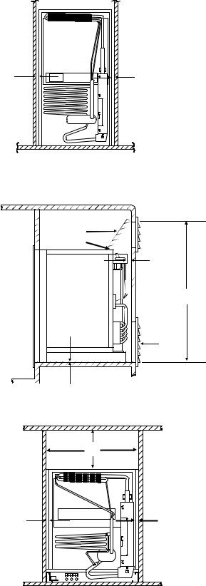
Side Wall Clearance - Figure 4
1. Figure 4 illustrates the requirement to minimize |
|
B |
|
the clearance at the sides of the refrigerator. |
|
|
|
The clearance is not to exceed 1/2 inch. Side |
|
|
|
clearances in excess of 1/2 inch must be either |
1 |
1 |
|
filled with Fiberglas batting or blocked with pan- |
|||
|
|
||
eling, etc. |
|
|
|
|
Figure 4 |
Upper Side Wall Exhaust Vent For Mod- |
1 |
|
els 452, 453, 442, and 443 ONLY |
||
Figure 5 |
2 |
|
|
|
|
1. |
Area above refrigerator blocked (baffled) off to |
4 |
|
prevent trapping of hot air above the refrigera- |
|
|
|
|
|
tor. |
|
2. |
0 - 1/4 inch clearance at the top of the refrig- |
3 |
|
erator. |
|
|
|
|
3. |
Upper Side vent Location. Floor level to top of |
|
|
opening. 38 1/8" for models 442 & 443. 50 1/2" |
6 |
|
for models 452 & 453. See Table 1 for vent |
|
|
5 |
|
|
dimensions, |
|
|
|
|
4. |
0 - 1 inch clearance at the rear of the refrigera- |
|
|
tor. (See Figure 3 when clearance exceeds 1 |
|
|
inch). |
|
5. |
Intake (lower) vent installed flush with the sur- |
Figure 5 |
|
face on which the refrigerator is mounted. |
|
|
|
|
6. |
O inch clearance at bottom of refrigerator. |
|
|
|
1 |
Top and Side Wall Clearance-All Models
Figure 6
1. |
Top baffle fills the total area above the refrig- |
2 |
2 |
|
erator an is properly aligned with the side wall |
|
|
|
construction. |
|
|
2. |
0 - 1/2 inch at the sides of the refrigerator. |
|
|
Figure 6
7
 Loading...