

Page 1

Nokia Customer Care
RH-29 Series Cellular Phones
3 - Service Software Instructions
Issue 1 05/2004 Copyright © 2004 Nokia Corporation Page 1
Company Confidential
Page 2

Company Confidential RH-29
Nokia Customer Care 3 - Service Software
Table of Contents
Page No
Service Software...................................................................................................................................... 4
Phoenix....................................................................................................................................................... 4
Supported Operating Systems ..........................................................................................................4
Hardware requirements for using Phoenix ...................................................................................4
Introduction ...........................................................................................................................................4
Starting a session ................................................................................................................................. 6
SW Update Flashing Setup ................................................................................................................... 8
FPS-8 Flash setup .................................................................................................................................8
POS Flash concept ................................................................................................................................9
Module Jig Flash concept .................................................................................................................10
RH-29 Phoenix installation instructions .....................................................................................10
FPS-8 to PC connection Setup instructions ................................................................................11
FPS-8 activation .................................................................................................................................11
Checking Application SW version inside FPS-8 .........................................................................11
SW update / Re-Flashing setups...................................................................................................... 13
POS Setup with FLS-4S Adapter ....................................................................................................13
DA-17 flash setup ..............................................................................................................................14
DA-17 SW update setup ...................................................................................................................14
Other setups .........................................................................................................................................15
Flashing ................................................................................................................................................... 16
Data package installation ................................................................................................................19
Reprogramming RH-29....................................................................................................................... 20
Connecting cables ..............................................................................................................................20
Proceed as follows: ............................................................................................................................20
Settings backup/restore ....................................................................................................................20
Updating software .............................................................................................................................21
Formatting user area .........................................................................................................................22
Restore settings ..................................................................................................................................22
Energy Management Calibration ..................................................................................................... 23
Connections .........................................................................................................................................23
Phoenix setup .................................................................................................................
Calibration ............................................................................................................................................23
ZOCUS calibration ..............................................................................................................................24
Phoenix Tuning...................................................................................................................................... 26
RF tuning after repairs ......................................................................................................................26
RX channel select filter calibration ...............................................................................................26
RX calibration (incl. VCXO Calibration) ........................................................................................27
RX AGC limits ......................................................................................................................................32
RX band filter response compensation .........................................................................................32
TX I/Q tuning ........................................................................................................................................37
TX power tuning ..................................................................................................................................48
Bit Error Rate Testing with JBT-9 .................................................................................................... 52
Hardware needed to use JBT-9 ......................................................................................................52
Use of JBT-9 stand-alone .................................................................................................................52
Attenuation settings ..........................................................................................................................52
Performing BER test ...........................................................................................................
Testing instructions for BER testing .............................................................................................54
.....................23
...............52
Issue 1 05/2004 Copyright © 2004 Nokia Corporation Page 2
Company Confidential
Page 3

Company Confidential RH-29
Nokia Customer Care 3 - Service Software
Additional menu functions ..............................................................................................................55
Attenuation setting via jumper ......................................................................................................56
LED indication of JBT-9 ....................................................................................................................56
JBT-9 Firmware Upgrade.................................................................................................................... 57
Issue 1 05/2004 Copyright © 2004 Nokia Corporation Page 3
Company Confidential
Page 4

RH-29 Company Confidential
3 - Service Software Nokia Customer Care
Service Software
Phoenix
Phoenix is the new generation Service Software. It has been designed to meet the challenges in servicing modern cellular phone technology.
The Phoenix program has been built using component architecture. This means that the
actual program is small and most of the program’s functionality is divided into dynamically loaded modules (DLLs).
Supported Operating Systems
Windows 98, 2000, ME and NT 4.0 (SP4).
Hardware requirements for using Phoenix
Minimum:
Processor 233 MHz, RAM memory 64 MB, Disk space 50-100 MB.
Recommended for Windows 2000:
Processor 700 MHz, RAM memory 512 MB, Disk space 50-100 MB.
Introduction
This section briefly describes how to install the Phoenix software and includes some
basic information on how to use the program. For more detailed information, please refer
to Phoenix’s Help -files. Each feature in Phoenix has its own Help function, which can
be activated while running the program.
Press the F1 key or the feature’s Help-button to activate a Help -file.
Installing Phoenix
1. Download the latest release. Please contact your regional After Market Services point
for information on where to download the latest release.
Download and read the release notes, which have useful information on the software
version you are using.
2. Download the latest data packages for the products you will be using.
3. Before you start installing the program, check that
- the dongle is attached to parallel port. Contact your supervisor in order to obtain a
suitable dongle.
- you have administrator rights (Windows 2000 or NT only). This is required in order to be
able to install Phoenix.
4. Install Phoenix by executing the Phoenix installation package and follow the instruc-
Page 4 Copyright © 2004 Nokia Corporation Issue 1 05/2004
Company Confidential
Page 5

Company Confidential RH-29
Nokia Customer Care 3 - Service Software
tions on the screen.
Initially the setup files are extracted into the file system.
Note: If the setup files are already extracted (left in the file system from previous installation) “Overwrite Protection” dialog appears. Always click "Yes to All" to overwrite the existing setup files.
5. The installation checks that the latest supported dongle driver version is installed. The
dongle driver is installed if there is no previous installation of the dongle driver or if the
installed dongle driver is older than the latest supported version.
Note: If the dongle driver is installed during installation, you need to reboot your PC and
restart the installation after reboot.
Program files are stored under “C:\Program Files\Nokia\Phoenix” (default).
6. Install the data package by executing the installation package and follow the instructions on the screen.
The data packages will create product specific directories under the installation directory.
Data files are stored under ”C:\Program Files\Nokia\Phoenix” (default).
Uninstalling Phoenix
If you need to remove Phoenix Service Software from your computer:
1. Make sure that the dongle is attached (unregistration).
2. Go to the Control Panel and select Add/Remove Programs.
3. Select RH-29 RELEASE for uninstallation and click Add/Remove.
4. Click OK to remove the application
You may have to reboot your PC after uninstallation.
Note: If you have different product packages installed, the components are uninstalled only if they are
not included in other product packages.
Data Packages
Data Packages (DP) is a name for a helpful feature in the Phoenix software. This type of
feature provides a flexible way of distributing and installing Phoenix and its data files.
All product-specific data is separated from the program code and installed separately.
This means that the installation is performed in at least two steps.
Each product will have its own Data Package (DP). The FPS-8 flashing equipment also has
its own package.
Issue 1 05/2004 Copyright © 2004 Nokia Corporation Page 5
Company Confidential
Page 6

RH-29 Company Confidential
3 - Service Software Nokia Customer Care
Starting a session
Concepts
In the Phoenix context, Product means the cellular phone attached to a PC. More specifically, it is a particular type of phone.
Connection means the type of cable used to attach the phone to the port to which the
other end of the cable is attached.
Selecting a product
Many of Phoenix’s features are product-specific. It is, therefore, mandatory to choose the
product you will be working on at the beginning of the session.
Select the menu item File - Choose Product. You will be presented with a list of available
products.
After the product selection, you will see an additional menu item on the main menu. If
you take a look at the available menu items, you will see that their number has
increased.
Selecting a connection
The connection defines the cable and the communications port that will be used when
connecting to the phone.
1. Active connections are listed in the toolbar’s Connection pull-down menu. You should
make sure that the connection is correct before using the software. Change it, if necessary.
In case the connection is the wrong, you need to create a new one.
2. Select Settings from the pull-down menu.
3. Select Add in the Connection List Dialog and in fill the relevant fields in the Connec-
tion setup dialog.
Phoenix environment
You can configure the program’s main toolbar and the product or tool -specific options
to your liking.
You can control which toolbars are visible by selecting View and Toolbars from the pulldown menu. The visible toolbars are marked with a check.
The rest of the options are product or tool -specific. The tool-specific options are set
using the associated toolbar.
Using components
When working with Phoenix, each task generally has its own component that will per-
Page 6 Copyright © 2004 Nokia Corporation Issue 1 05/2004
Company Confidential
Page 7

Company Confidential RH-29
Nokia Customer Care 3 - Service Software
form the task. The first thing, therefore, is to open the desired component.
Opening a component means that you open a tool window within Phoenix. When this
window is opened, Phoenix also opens a toolbar for it and adds component-specific
menu items in the View menu.
Using profiles
A Profile is a useful feature in the software. Product, connection and currently open
components can be stored into a permanent storage (a disk file called profile, *.nmp) for
later retrieval.
Opening and saving profiles is done via menu commands found in the File menu. Select
Open Profile and Save Profile.
Since profiles are stored into a disk file with the user-defined name, there can be multiple profiles for different repeated tasks.
Issue 1 05/2004 Copyright © 2004 Nokia Corporation Page 7
Company Confidential
Page 8
RH-29 Company Confidential
3 - Service Software Nokia Customer Care
SW Update Flashing Setup
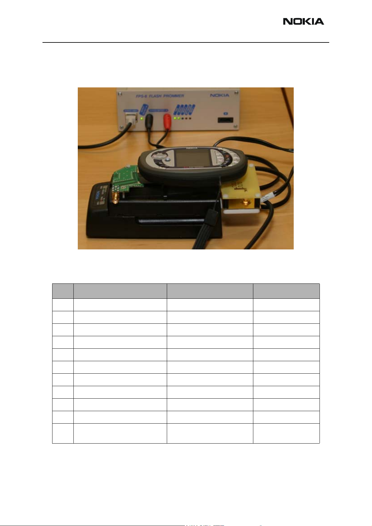
FPS-8 Flash setup
The following equipment is required for RH-29 AMS SW update, when connecting RH-29
to PC with FPS-8:
Item Description Type Code
1 Docking station adapter DA-17 (use with JBV-1) 0770701
1a Point of Sales flash loading adapter FLA-48 0770582
2 Power cable PCS-1 0730012
3 Power cable FLC-2 0730185
4 Modular cable XCS-4 0730178
5 Flash prommer box sales pack FPS-8 0080321
6 Printer cable AXP-8, incl. in FPS-8 sales pack
7 D9 – D9 cable AXS-4, incl. in FPS-8 sales pack 0730090
8 Software protection key PKD-1 0750018
9 AC Charger, incl. in FPS-8 sales pack 0680032
10 SRAM Module (2 pcs needed inside
FPS-8)
SF12 0080346 (Code includes
one SRAM module)
Page 8 Copyright © 2004 Nokia Corporation Issue 1 05/2004
Company Confidential
Page 9
Company Confidential RH-29
Nokia Customer Care 3 - Service Software
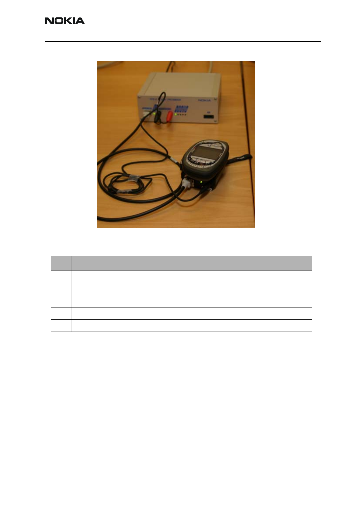
POS Flash concept
The following equipment is required for RH-29 AMS SW update, at point of sale when
connecting RH-29 to PC with FLS-4:
Item Description Type Code
1 Point of Sales flash loading adapter SF-20 0770702
2 Service cable XCS-1 0730218
3 FLS-4S sates pack for E & A FLS-4S 0080541
4 FLS-4S sates pack for APAC FLS-4S 0080542
5 FLS-4S sates pack for US FLS-4S 0080543
Issue 1 05/2004 Copyright © 2004 Nokia Corporation Page 9
Company Confidential
Page 10
RH-29 Company Confidential
3 - Service Software Nokia Customer Care
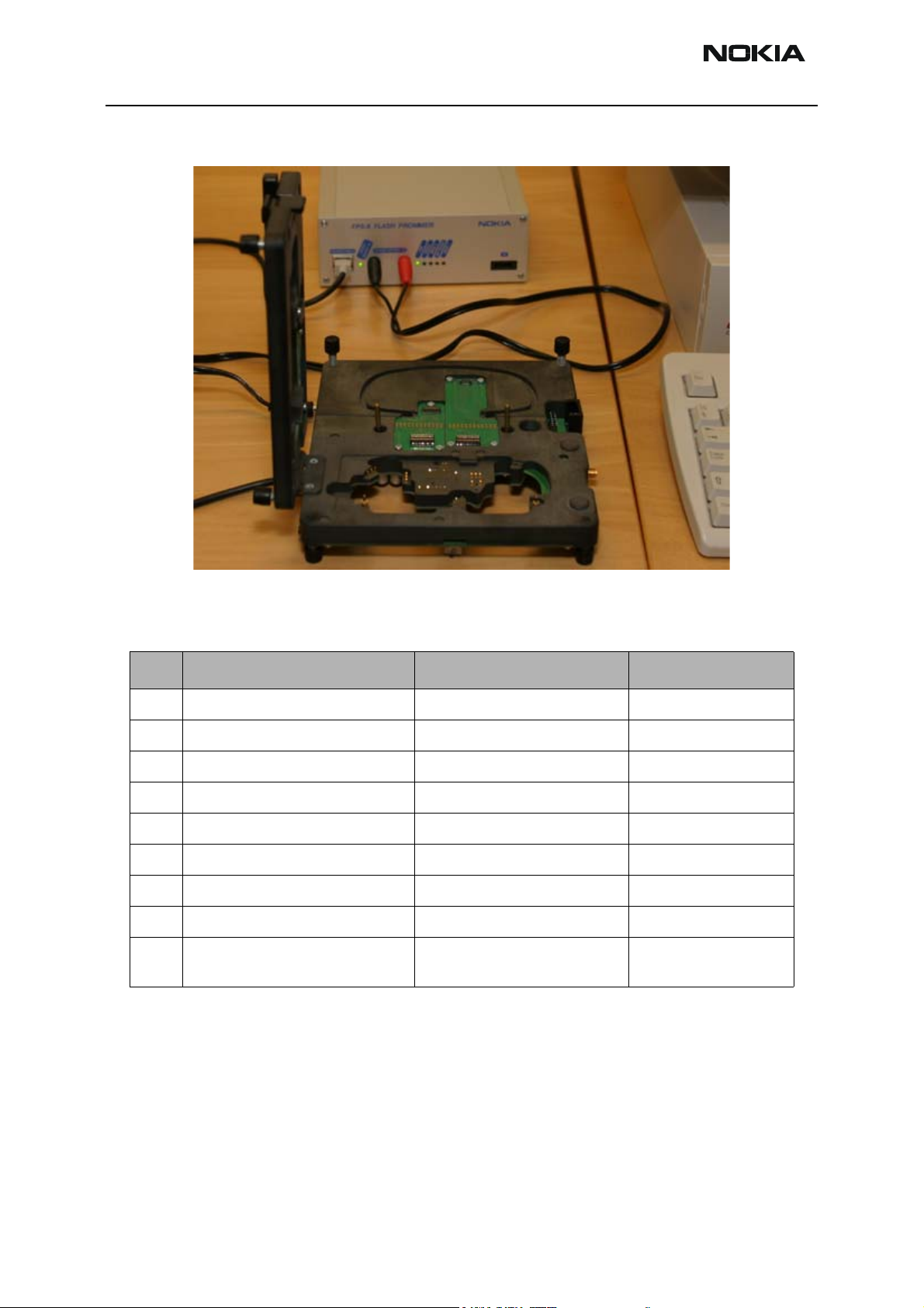
Module Jig Flash concept
The following equipment is required for RH-4 AMS SW update when system module is
placed in the Module Jig DA-17 and connected through a FPS-8 set-up:
Item Description Type Code
1 Module Jig DA-17 0770646
2 Power cable PCS-1 0730012
3 Modular cable XCS-4 0730178
4 Flash prommer box sales pack FPS-8 0080321
5 Printer cable AXP-8, incl. in FPS-8 sales pack
6 D9 – D9 cable AXS-4, incl. in FPS-8 sales pack 0730090
7 Software protection key PKD-1 0750018
8 AC Charger, incl. in FPS-8 sales pack 0680032
9 SRAM Module (2 pcs needed inside
FPS-8)
SF12 0080346 (Code includes
one SRAM module)
Note: All tunings except Zocus calibration can be done with JBV-1/DA-17 concept by
using XRF12 RF cable.
RH-29 Phoenix installation instructions
Now that cables have been connected, you must install RH-29 version of Phoenix to your
PC.
• 4.13.005 is currently the newest available RH-29 AMS Phoenix SW
Page 10 Copyright © 2004 Nokia Corporation Issue 1 05/2004
Company Confidential
Page 11

Company Confidential RH-29
Nokia Customer Care 3 - Service Software
NOTE! Y ou must use 2003.17.3.12 Phoenix release in order to get new SW into your RH-29
phone.
• Save the package to your hard disk and install it by double-clicking it.
NOTE! It is recommended that you uninstall previous Phoenix package before installing the new one.
Do it as follows:
• Click Start -> Settings -> Control Panel
• Add/Remove Prog.
• Phoenix RH-29 release
• Add/Remove
Reboot your computer after uninstallation
FPS-8 to PC connection Setup instructions
Establish connection between your PC and FPS-8. The procedure is as follows:
• Start phoenix
• Choose File -> Manage connections
• Choose Add
• Select mode, select Manual
• As Media, select FPS-8
• Port number, select the port where you have connected the serial cable
of FPS-8.
• COMBOX_DEF_MEDIA, select FBUS
• Click on Finish
•Press Arrow up key so that FPS8 COM1 FBUS becomes the first on
the list.
• Press Apply and close the window
The connection between PC and FPS-8 has now been configured.
FPS-8 activation
Follow the instructions inside FPS-8 sales pack to get FPS-8 activated.
Issue 1 05/2004 Copyright © 2004 Nokia Corporation Page 11
Company Confidential
Page 12
RH-29 Company Confidential
3 - Service Software Nokia Customer Care
Checking Application SW version inside FPS-8
When you have connection established to FPS-8 and FPS-8 has been activated, the first
thing to do is to check that you have correct application SW version inside FPS-8. Phoenix SW can check that automatically. The procedure goes as follows:
Go to the partner web site and take newest AMS FPS-8 SW.
Instructions:
• Click FPS-8 downloads
• Click Flash Update
• Click AMS/Production version
• Click 2.10.000
• Take file flash_update_02_10_000.exe
• Save it to your hard drive to a place which you can remember
• Go to that directory and click on flash_update_02_10_000.exe
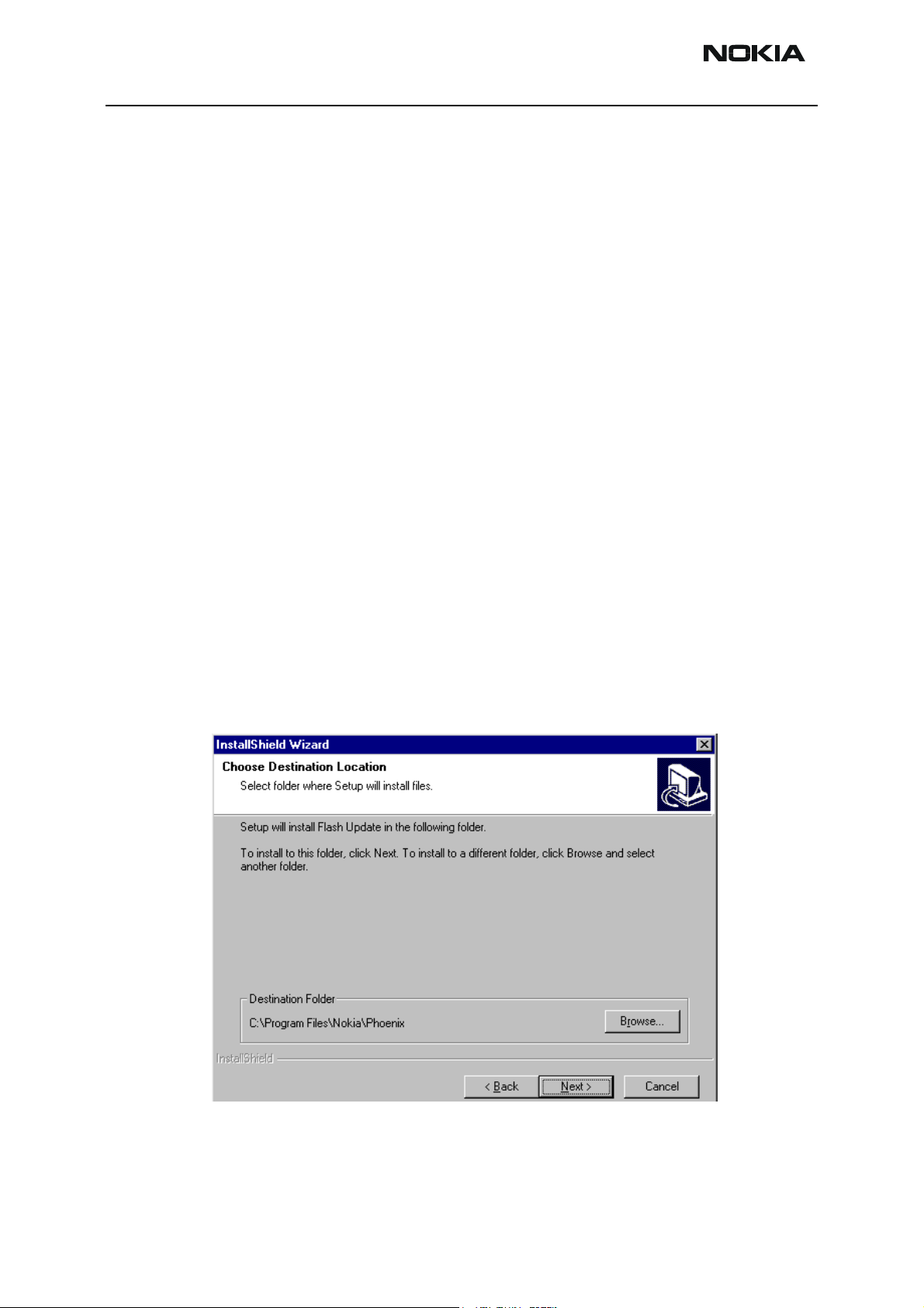
You will see the following note on your screen. Install files to the directory which installation program suggests to you.
Figure 1: Install Shield Wizard screen
When the installation has been finished, FPS-8 files are located in that directory.
Page 12 Copyright © 2004 Nokia Corporation Issue 1 05/2004
Company Confidential
Page 13

Company Confidential RH-29
Nokia Customer Care 3 - Service Software
You can now start phoenix SW.
When phoenix SW has stared, do the following:
Click on flashing
Click on FPS-8/FPS-8C Maintenance
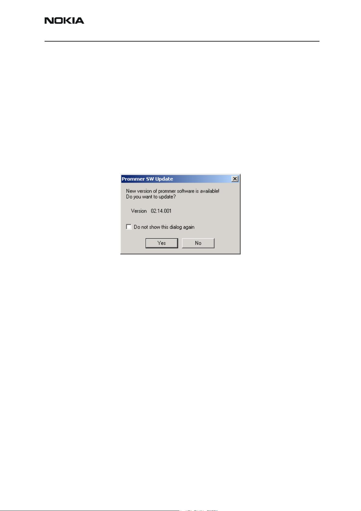
If SW inside FPS-8 prommer is too old, you get the following notification:
Figure 2: Prommer SW update screen
Click Yes and you see on the small scree as the Prommer goes to service mode (mode2 is
lit) SW goes into box, application SW, Secondary boot codes and algorithm codes are
updated.
There is no longer need to do anything special with RH-29 specific Secondary boot codes
and algorithm codes.
Your PC and FPS-8 is now ready for RH-29 SW update.
SW update / Re-Flashing setups
The following setup diagram shows how to connect the different service devices when
flashing the RH-29 phone. Make sure that you have selected the right one before proceeding.
For the part codes of the required accessories, please refer to the Service Accessory
chapter.
Issue 1 05/2004 Copyright © 2004 Nokia Corporation Page 13
Company Confidential
Page 14
RH-29 Company Confidential
3 - Service Software Nokia Customer Care
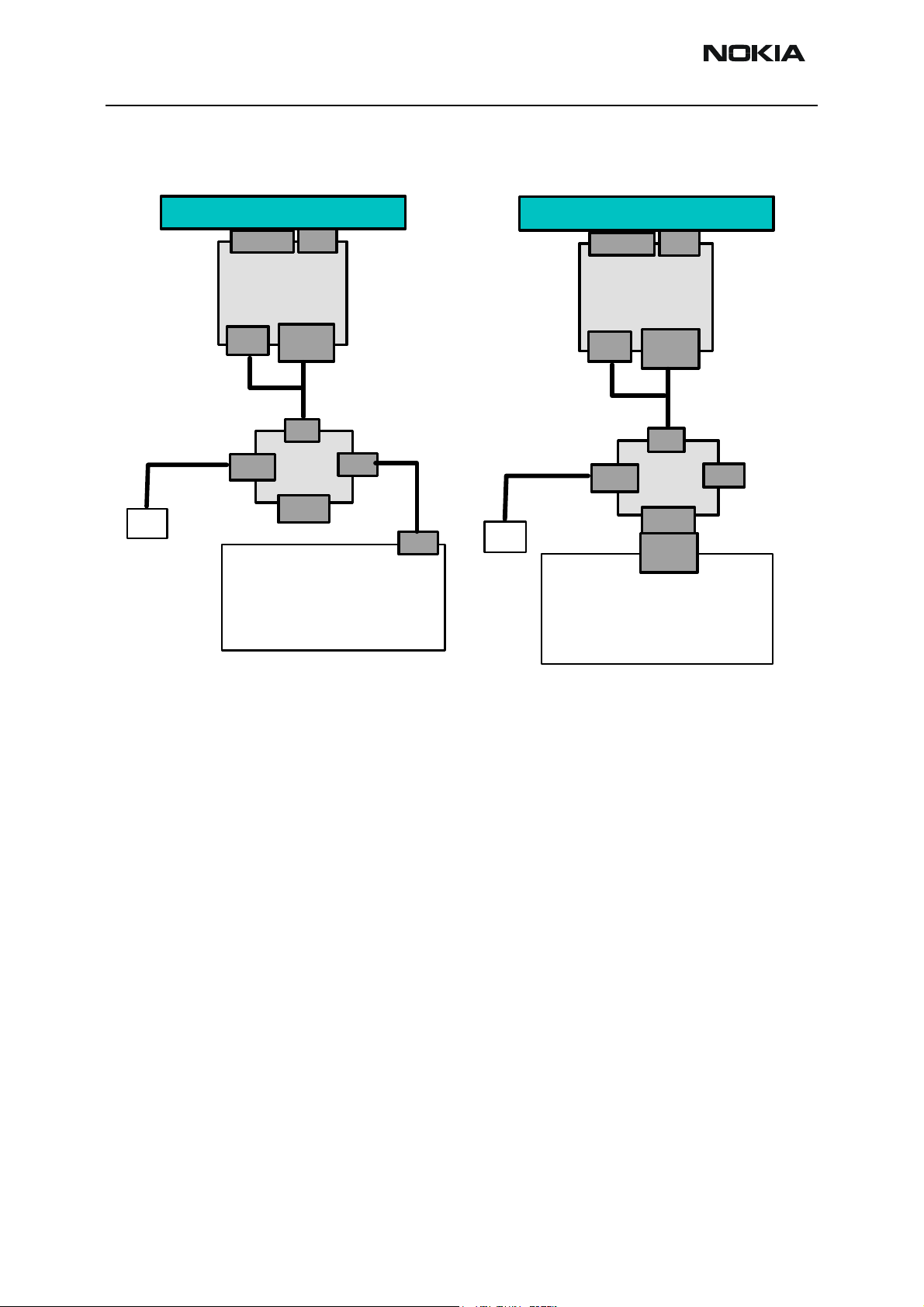
POS Setup with FLS-4S Adapter
As main interface either USB or Parallel port can be used. See figures below:
ACF-8
Device Under Test
Test/Flash IF
Battery
SF-20
DC IN
ACF-8
MS Windows PC / Laptop
Data
XCS-1
Phone
FLS-4S
LPT Port
PC USB
with Phoenix SW
PC USB
USB
cable
ACF-8
Device Under Test
Test/Flash IF
Battery
SF-20
DC IN
ACF-8
MS Windows PC / Laptop
with Phoenix SW
Data
XCS-1
Phone
FLS-4S
LPT Port
LPT x
PORT
PC USB
Figure 1: USB interface setup Figure 2: Parallel port setup
Page 14 Copyright © 2004 Nokia Corporation Issue 1 05/2004
Company Confidential
Page 15
Company Confidential RH-29
Nokia Customer Care 3 - Service Software
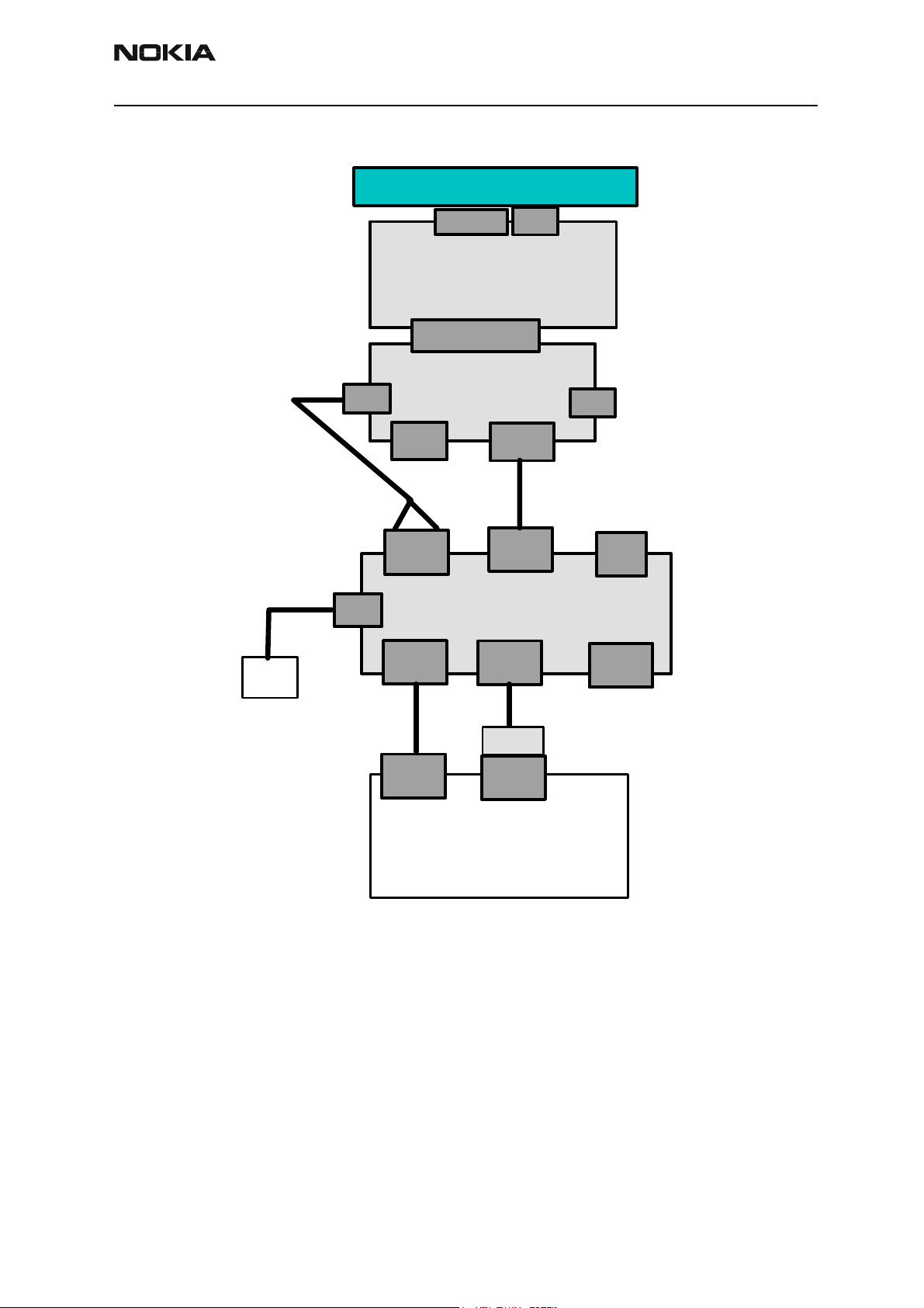
DA-17 flash setup
Device Under Test
ACF-8
DC IN
PCS-1
Power
Adapter Connector
USB
Service
Battery
Serial
Input
Test/Flash IF
DA-17
(25 pol Sub-D)
JBV-1
XCS-4
FPS-8
DATA
Service
Cable
Parallel
Input
Battery
DC OUT
Connector
IR
Phone
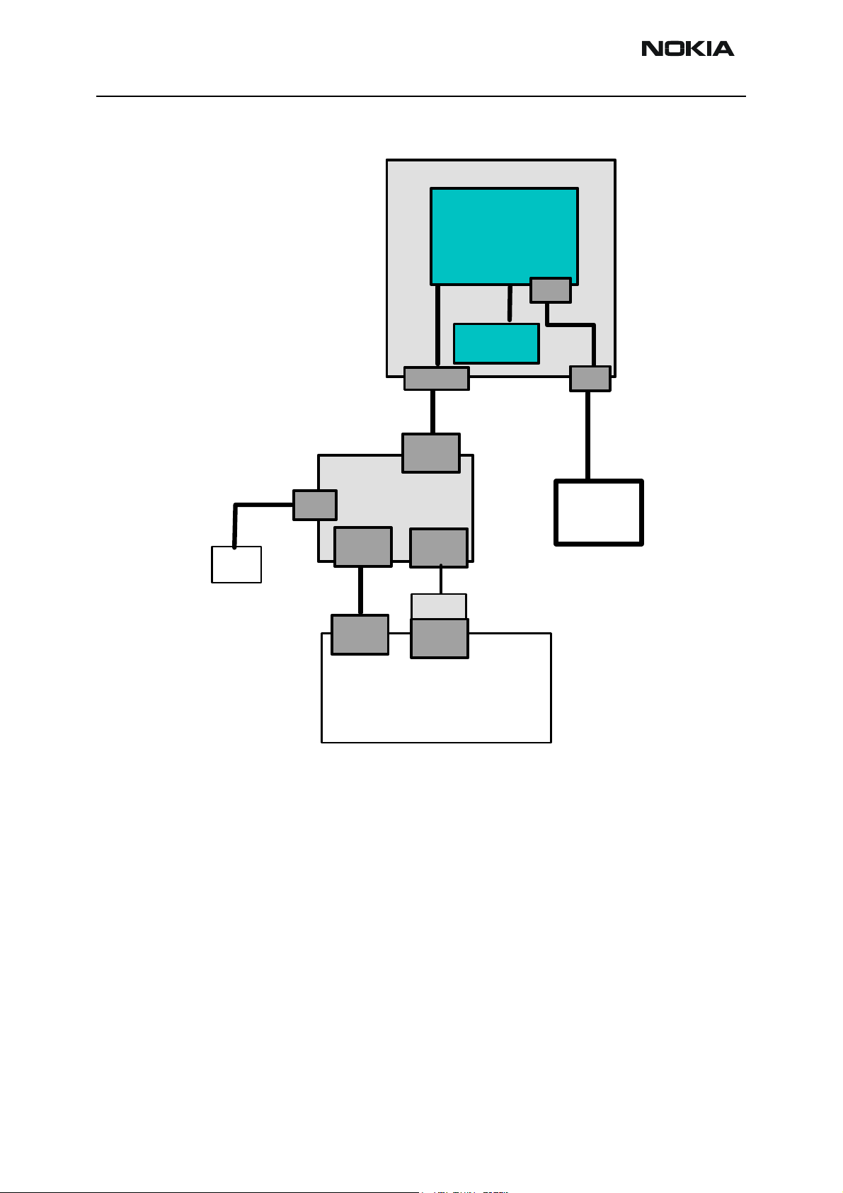
DA-17 SW update setup
Module repair jig flashing is possible with the following setup. Usually additional equip-
AXP-8
AXS-4
PKD-1x
COM x
PORT
LPT x
PORT
MS Windows PC / Laptop
with Phoenix SW
Issue 1 05/2004 Copyright © 2004 Nokia Corporation Page 15
Company Confidential
Page 16
RH-29 Company Confidential
3 - Service Software Nokia Customer Care
ment is connected for further repair activities.
MJ-21
Main PWB
Battery
UI PWB&LCD
& Keypad
ACF-8
Power
Test/Flash IF
XCS-4
Service
Cable
FPS-8
Serial
Input
AXS-4
COM x
PORT
MS Windows PC / Laptop
with Phoenix SW
Parallel
Input
PKD-1x
LPT x
PORT
AXP-8
DC IN
PCS-1
Power Supply
4 V / 2A DC
Other setups
There are also other possible flash setup combinations, but these are rarely used.
Page 16 Copyright © 2004 Nokia Corporation Issue 1 05/2004
Company Confidential
Page 17
Company Confidential RH-29
Nokia Customer Care 3 - Service Software
Flashing
First ensure that all cables are connected according to one of the diagrams above
(depending on the case)! See the respective chapter about connecting FPS-8 to PC.
Start Phoenix
Ensure that the latest AMS version of Phoenix is installed (Help-> About Phoenix). If a
newer version is available you must install it (see Service SW Instructions for help
installing Phoenix)
Go to Flashing -> FPS-8 maintenance
If SW in FPS-8 is old, you will get the following message:
Press OK and wait until the prommer is updated.
Now you are ready to flash the phone.
Remove the SIM card and MMC card from the phone.
Turn the phone ON.
Scan the phone by pressing Ctrl + R (Make sure that the phone is loaded: the phone type
as well as the SW version should be displayed in the status line).
If no product is found, then choose RH-29 manually: File -> Open Product, and then
select RH-29.
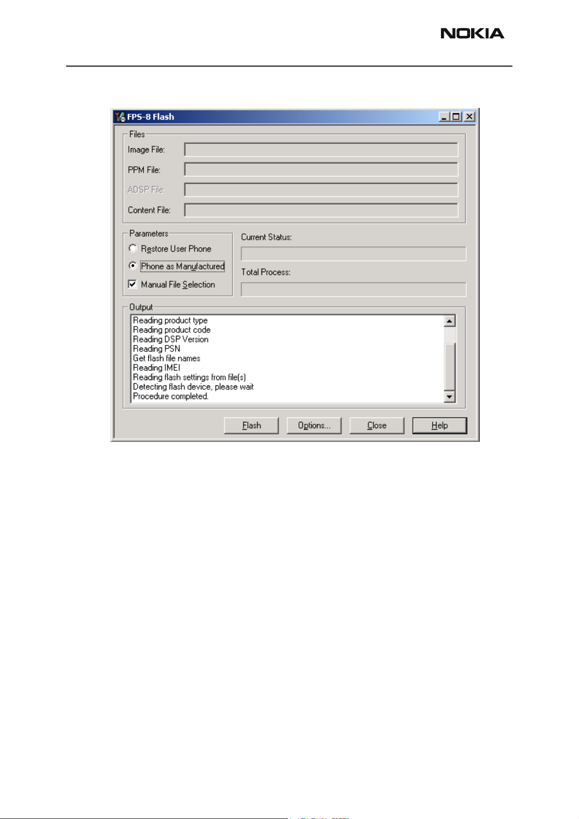
Go to Flashing -> FPS-8 flash.
Issue 1 05/2004 Copyright © 2004 Nokia Corporation Page 17
Company Confidential
Page 18
RH-29 Company Confidential
3 - Service Software Nokia Customer Care
The following window appears:
Ensure that there is a data package installed: in this case the MCU, PPM and Content
package files will be displayed automatically in the respective fields. Otherwise install a
data package file (see related chapter).
Disable “Manual file selection” and press Flash.
In case a special SW version is needed, which is different than the currently displayed:
Enable “Manual file selection” and press Flash.
Page 18 Copyright © 2004 Nokia Corporation Issue 1 05/2004
Company Confidential
Page 19

Company Confidential RH-29
Nokia Customer Care 3 - Service Software
The following window appears:
In case a data package is installed: In Product drop-down menu select RH-29, and in
Product Code drop down menu select the SW variant you want to flash. Finally click OK.
In case no data package is installed: Browse and choose manually the desired MCU,
PPM and Content package files and click OK.
If an error message appears “Turn the power on and select OK” at the end of the flash
process: disconnect the phone completely and connect it again, press the power button
of the phone, wait about 15 sec. and press OK.
If the phone does not turn on, then the MCU SW version does not match the phone’s
HW and SW update is not possible.
After the phone is successfully flashed, the user area should be formatted.
Issue 1 05/2004 Copyright © 2004 Nokia Corporation Page 19
Company Confidential
Page 20

RH-29 Company Confidential
3 - Service Software Nokia Customer Care
Go to Product –> User area format. The following window appears:
Press OK and wait until you get a confirmation that the user area is successfully formatted.
FLS-4S flashing
Connect all cables of FLS-4S as shown in the diagrams presented in section POS Setup
with FLS-4S Adapter (use either Parallel port or USB).
Disconnect FPS-8 completely from the PC.
Make sure that you have the latest FLS-4S driver installed (in Windows: Settings -> Con-
trol Panel - > FLS virtual port).
The flashing process is the same as with FPS-8.
Go to Flashing -> FLS-4S flash and repeat the steps presented in the previous section
(FPS-8 flashing).
Data package installation
Find out whether there is a data package installed in Windows: Settings -> Control Panel
-> Add Remove programs.
If the current data package is old, please remove it. Then download the latest data package for RH-29 to your hard disk: RH-29_dp_v_0_02_MCUSW1_55.exe.
Close Phoenix, double click the file and follow the instructions displayed on the screen.
Page 20 Copyright © 2004 Nokia Corporation Issue 1 05/2004
Company Confidential
Page 21

Company Confidential RH-29
Nokia Customer Care 3 - Service Software
Reprogramming RH-29
Connecting cables
Once you have the RH-29 opened and the battery and SIM removed, attach it to the FLA48 adapter. Once connected to the FLA-48 the phone goes to local mode and the screen
will not show anything during SW update.
Proceed as follows:
• Connect XCS-4 cable from FLA-48 to FPS-8
• Connect FLC-2 cable from FPS-8 to FLA-48
• There is no need to press the phone power key. Phone has set itself
automatically to local mode and it is now ready for SW update.
Settings backup/restore
It is quicker to use MMC user data backup, which can be found at: Menu > extras >
memory > options > backup phone memory.
Start Phoenix SW by double-clicking the Phoenix icon on your desktop.
• Now choose File -> Scan product. If phone is ok, you should see the
SW version in lower right-hand corner, e.g. V3.1
• If the scanning finds nothing, the phone is most likely in some strange
mode.
Settings Backup:
• Click Product
•Click User settings
•Click All Settings
•Click Browse
• Choose from Directory C:\Program files\Nokia\Phoenix\Products\
file Nhl8sett.ini
You will now see the following PC screen:
Issue 1 05/2004 Copyright © 2004 Nokia Corporation Page 21
Company Confidential
Page 22

RH-29 Company Confidential
3 - Service Software Nokia Customer Care
Figure 3: All settings screen
Updating software
New SW package can be updated.
• Choose Flashing -> FPS-8 Flash -> Mark both log flashing and Manual Selection. Then Click on Flash.
• Now in Flash file selection window, choose the product code.
Select the correct file:
Now click on OK, and SW update starts.
You will see as the 18 MB package goes into FPS-8 (If transfer is very slow, it is recommended that Parallel port is in ECP mode. Transfer in ECP mode is much faster).
If you do not know how to Change PC Parallel port mode from BIOS, contact your local
support.
Then Phoenix erases flash memories.
And finally you will see how SW package goes into phone (When SW update takes place,
Yellow Mode 1 led is blinking fast)
When SW update has ended yellow led stops blinking and you get a note in windows SW.
Page 22 Copyright © 2004 Nokia Corporation Issue 1 05/2004
Company Confidential
Page 23

Company Confidential RH-29
Nokia Customer Care 3 - Service Software
You will get instructions to turn the phone on. Do so and wait 15 seconds.
Formatting user area
User area also needs to be formatted in order to make sure that there is no user data left
in the phone.
Choose File -> Scan product. In the bottom of the Phoenix window you should see
V3.1, Date, RH-29(c) NMP
Format User area the following way:
Click Product -> User area format. You will get a note warning you about loss of user
data. Click yes on that.
Phoenix shows Formatting user data area, Please wait screen for a while and gives you a
success note.
Restore settings
Settings can be restored from MMC or Phoenix.
Issue 1 05/2004 Copyright © 2004 Nokia Corporation Page 23
Company Confidential
Page 24

RH-29 Company Confidential
3 - Service Software Nokia Customer Care
Energy Management Calibration
Connections
RH-29 phone must be connected to JBV-1 (Docking station) with DA-17 (Docking station
adapter).
• Connect CA-5S (DC-DC cable) from JBV-1 into to phone charger connector before powering up JBV-1.
• Power up JBV-1 from external power supply: 11-16 V DC. (Do not take
power from FPS-8 in calibration mode).
Phoenix setup
• Start Phoenix.
• Select FBUS connection.
• Choose Main -> Choose product…
• Choose Maintenance -> Tuning -> Energy Management Calibration
Calibration
1) Mark all channels (ADC, Battery Size…except Battery temperature).
component.
Figure 4: Energy Management Calibration screen
2) Press Calibrate button.
Page 24 Copyright © 2004 Nokia Corporation Issue 1 05/2004
Company Confidential
Page 25

Company Confidential RH-29
Nokia Customer Care 3 - Service Software
After successful calibration Calibrated indication is shown.
3) Press Save To Phone to save tuning values into phone memory.
After successful saving Values written to phone is indicated.
4) Verify tuning values saving by pressing Read from Phone.
ZOCUS calibration
Zocus requires re-calibration only if the Zocus device itself is replaced, any of the components on the sense input (R383, R384 and C386) or if the flash memory is corrupted.
Zocus does not require recalibration if the UEM device is replaced or if any of the other
energy management calibrations are recalibrated.
1 Place the PWB in the module jig.
2 Connect an ammeter across the ammeter + and ammeter - connections.
3 Set switch S2 to the calibration position.
4 Power up the module jig in local mode - the ammeter will indicate the local
mode current.
5 Connect the charger input to a power supply set to 8.4V and current limited to
500mA. Turn power supply on.
6 Open the Zocus EM window in Phoenix.
7 Click on “Close the Charge Switch”.
8 Adjust the current limit on the power supply until the ammeter reads 500mA
±5mA.
9 Type the measured current (read this from the ammeter) into the “Measured Cur-
rent” box. The value is negative and presented in Amps e.g. if you measure
502mA, then type -0.502. The reading should be to the nearest mA.
10 Click the “Calibrate” button.
11 If you wish to check the calibrated value then do not choose to close the charge
switch. The calibrated current value will appear in the Zocus_Cal_Current window.
12 The calibration value appears in the box Zocus_New_Cal. To write this to the
Issue 1 05/2004 Copyright © 2004 Nokia Corporation Page 25
Company Confidential
Page 26

RH-29 Company Confidential
3 - Service Software Nokia Customer Care
phone click “Write”.
Page 26 Copyright © 2004 Nokia Corporation Issue 1 05/2004
Company Confidential
Page 27

Company Confidential RH-29
Nokia Customer Care 3 - Service Software
Phoenix Tuning
Connect the phone to a PC running the Phoenix Service Software.
Start Phoenix Service Software and open FBUS connection
Select File Scan Product
Wait until phone information is shown in the lower right corner of the screen.
RF tuning after repairs
Different repairs require different tuning. In general it is necessary to determine in which
section the repair was done to select which tunings to perform. To determine if RF tuning
is necessary after repair it is important that the functionality of the repaired circuit is
understood well. It is recommended to perform complete RF tuning if RF is repaired.
• In general repairs in the TX part will require "TX Power Level Tuning"
and "TX IQ Tuning".
• In general repairs in the RX part or PLL part always require "RX Calibration", “Rx Band Filter Response Calibration”.
• If Mjoelner is changed all calibrations have to be done.
Other parts interfacing to TX, RX or PLL might require tuning, but common sense should
be used, e.g. if a component that has no influence on RF performance has been changed,
e.g. the microphone, on/off key, mechanical parts or similar, there is no need to do any RF
tuning.
RX channel select filter calibration
This calibration is calibrating the Base band filter inside Mjoelner. It is done by internally
measuring a prototype filter, for this reason the calibration is done once, not separately
in 2 bands.
Set operating mode to local mode
Select Tuning Alt-U
RX Channel Select filter Calibration F
Issue 1 05/2004 Copyright © 2004 Nokia Corporation Page 27
Company Confidential
Page 28

RH-29 Company Confidential
3 - Service Software Nokia Customer Care
The setup should now look like this:
Press Tune and the optimal values are found.
Make sure that Save to Phone is active. It can be activated by clicking with mouse or by
pressing the letter v.
Press Stop and the RX Channel Select Filter Calibration is finished. You can now leave the
tuning by closing the window.
RX calibration (incl. VCXO Calibration)
The "RX calibration" is used to determine gain at different gain-settings for front-end
and Mjoelner and needs to be done in both bands.
RX-calibration requires an external signal generator.
RX-calibration in EGSM900 combines two tunings, VCXO-calibration and AGC-calibration:
Calibration of GSM1800 band only determines AGC values.
The VCXO-calibration finds out a calibration value for VCXO control, an AFC initial
value and 3 AFC-slope coefficients.
A value (RF_TEMP), which represents the RF hardware temperature, is determined during
RX Calibration. This temperature value is used by DSP to RSSI reporting in Normal mode
Page 28 Copyright © 2004 Nokia Corporation Issue 1 05/2004
Company Confidential
Page 29

Company Confidential RH-29
Nokia Customer Care 3 - Service Software
of the phone. It is not visible in the calibration process.
AGC-calibration:
The AGC-calibration finds the gain values of the RX-gain system.
The AGC consists of RF LNA, which can be either on or off (gain difference between on
and off state is nominally 30dB) and BB gain which can be controlled in 6dB steps. This
gives 15 gain steps RSSI0 to RSSI14. LNA is off for steps RSSI0 to RSSI4.
AGC-calibration measures the gain at gain step RSSI4 and RSSI7. The other gain values
are calculated.
VCXO-calibration:
The VCXO-calibration ensures the function of an initial synchronization (before location
update is done) when the mobile station is in Normal mode. For an error free initial synchronization, the 26MHz frequency of the VCXO must be accurate enough. Therefore, a
VCXO cal value is written into the RefOSCCAL register of the Mjoelner.
During VCXO-calibration, the VCXO cal value is changed by a DSP-algorithm until a synchronization is possible. This means the VCXO oscillates at 26 MHz with a sufficient minimum frequency error.
To further minimize the frequency error, an initial AFC value is determined by the DSP
and written into RefOSCAFC register of the Mjoelner.
Also the DSP algorithm determines 3 AFC slope coefficients Slope C1...3 during VCXO
calibration. One AFC slope value is not sufficient for Mjoelner F3, because the AFC slope
is non-linear in this chip.
EGSM900 and DCS1800
Select Tuning Alt-U
Wait until the RX Calibration window pops up.
Select Band GSM900
RX Calibration C
Issue 1 05/2004 Copyright © 2004 Nokia Corporation Page 29
Company Confidential
Page 30

RH-29 Company Confidential
3 - Service Software Nokia Customer Care
The setup should now look like this:
Press Start and a new window pops up:
Connect an external signal generator to the RF connector of the phone and set the generator as told in the window, taking care for external cable losses.
Press OK and the window closes.
Page 30 Copyright © 2004 Nokia Corporation Issue 1 05/2004
Company Confidential
Page 31

Company Confidential RH-29
Nokia Customer Care 3 - Service Software
A typical result will look like this:
The EGSM900 has been tuned. To proceed to DCS1800 tuning, press Save & Continue
and a new window pops up:
Let an external signal generator be connected to the RF connector of the phone and set
the generator as told in the window, taking care of external cable losses.
Press OK and the window closes.
Issue 1 05/2004 Copyright © 2004 Nokia Corporation Page 31
Company Confidential
Page 32

RH-29 Company Confidential
3 - Service Software Nokia Customer Care
A typical result will look like this:
Press Save and Continue, and a new window pops up:
Press OK and the RX Calibration of the EGSM900 and DCS1800 are finished.
Page 32 Copyright © 2004 Nokia Corporation Issue 1 05/2004
Company Confidential
Page 33

Company Confidential RH-29
Nokia Customer Care 3 - Service Software
RX AGC limits
The Rx calibration is only valid if it is within certain limits.
For the most recent limits see RH-29 Production Testing Requirements,
If calibration is not within limits, there is a fault in the RX chain.
Below the values for RSSI4 and RSSI7 are given:
RSSI4:
Table 1:
band min typ max
EGSM900 81 86 91
DCS1800 79 85 89
RSSI7:
Table 2:
band min typ max
EGSM900 103 108 11 3
DCS1800 100 104 11 0
RX band filter response compensation
EGSM900 and DCS1800
Set operating mode to local mode
Select Tuning Alt-u
RX Band Filter Response Compensation B
Select Band EGSM900
Issue 1 05/2004 Copyright © 2004 Nokia Corporation Page 33
Company Confidential
Page 34

RH-29 Company Confidential
3 - Service Software Nokia Customer Care
The setup should now look like this:
Select Input Signal Level -60dBm
Manual tuning
Press Manual tuning and a window pops up:
Connect an external signal generator to the RF connector of the phone and set the generator as told in the window.
Page 34 Copyright © 2004 Nokia Corporation Issue 1 05/2004
Company Confidential
Page 35

Company Confidential RH-29
Nokia Customer Care 3 - Service Software
Press OK and a new window pops up:
Set the generator as told in the window.
Press OK and a new window pops up. Repeat this sequence 9 times until all channels are
done.
A typical result will look like this:
The EGSM900 has been tuned. Press Save and Continue to proceed to DCS1800 tuning.
Issue 1 05/2004 Copyright © 2004 Nokia Corporation Page 35
Company Confidential
Page 36

RH-29 Company Confidential
3 - Service Software Nokia Customer Care
A window pops up:
Let the external signal generator be connected to the RF connector and set the generator
as told in the window, taking care of external cable losses. Press OK and the following
window pops up:
Set the generator as told in the window.
Press OK and a new window pops up. Repeat this sequence 9 times until all channels are
done.
Page 36 Copyright © 2004 Nokia Corporation Issue 1 05/2004
Company Confidential
Page 37

Company Confidential RH-29
Nokia Customer Care 3 - Service Software
A typical result will look like this:
Select Input Signal Level -60dBm
The DCS1800 has been tuned. Press Save and Continue to finish the tuning. A new window pops up:
Issue 1 05/2004 Copyright © 2004 Nokia Corporation Page 37
Company Confidential
Page 38

RH-29 Company Confidential
3 - Service Software Nokia Customer Care
TX I/Q tuning
This tuning must be done in both bands.
EGSM900
Caution: In case you use a spectrum analyser make sure that the external attenuation (20 - 30dB)
between phone and spectrum analyser is high enough that the input of the analyser can’t be destroyed.
Adjust the reference level offset according to the insertion loss from the phone to the spectrum analyser.
PC/Phone operation:
Set operating mode to local mode
Select Tuning Alt-u
TX IQ Tuning I
Wait until the TX IQ Tuning window pops up.
Select Testing Alt-s
RF Controls R
Wait until the RF Controls window pops up.
Connect a Spectrum Analyzer or GSM tester with the option *Narrow Spectrum' to the
RF connector of the phone.
If a spectrum analyzer is used then use the following settings.
Table 3:
EGSM900
Center Frequency 897.4 MHz
Frequency Span 200 kHz
Resolution Bandwidth 3kHz
Video Bandwidth 3kHz
Sweep Time 3 sec.
Sweep Type Clear/Write
Detector Type Max Peak
Reference level 35 dBm
Marker 1 897.33229 MHz
Marker 2 897.4 MHz
Marker 3 897.46771 MHz
Page 38 Copyright © 2004 Nokia Corporation Issue 1 05/2004
Company Confidential
Page 39

Company Confidential RH-29
Nokia Customer Care 3 - Service Software
Select in the RF Controls Window:
Select Band GSM900
Active Unit TX
Operation Mode Burst
RX/TX Channel 37
TX PA Mode Free
TX Data Type All1
Press Start
The following window pops up:
Select again in the RF Controls Window:
Select TX Power Level 5
Issue 1 05/2004 Copyright © 2004 Nokia Corporation Page 39
Company Confidential
Page 40

RH-29 Company Confidential
3 - Service Software Nokia Customer Care
The setup should now look like this:
Page 40 Copyright © 2004 Nokia Corporation Issue 1 05/2004
Company Confidential
Page 41

Company Confidential RH-29
Nokia Customer Care 3 - Service Software
The Spectrum Analyzer now shows a plot like this:
The purpose of this tuning is to tune the carrier signal and the +67kHz signal to a minimum level
(Marker 2 and 3).
Use the variables 'TX I DC offset' and 'TX Q DC offset' to adjust the carrier signal to a
minimum level (Marker 2).
After tuning to the minimum the level difference between the peak levels at marker 1
and 2 must exceed 40dB.
Tuning is possible by using arrow keys on the keyboard. Pushing the sliders by using the
mouse is less sensitive but even possible.
Issue 1 05/2004 Copyright © 2004 Nokia Corporation Page 41
Company Confidential
Page 42

RH-29 Company Confidential
3 - Service Software Nokia Customer Care
The Spectrum Analyzer now shows a plot like this:
Use the variables 'Amplitude difference' and 'Phase difference' to adjust the +67kHz signal to a minimum level (Marker 3). After tuning to the minimum the level difference
between the peak levels at marker 1 and 3 must exceed 40dB. Tuning is possible by using
arrow keys on the keyboard. Pushing the sliders by using the mouse is less sensitive but
even possible.
Page 42 Copyright © 2004 Nokia Corporation Issue 1 05/2004
Company Confidential
Page 43

Company Confidential RH-29
Nokia Customer Care 3 - Service Software
The Spectrum Analyzer now shows a plot like this:
Select again in the RF Controls Window:
Select “Save and Continue”
Press Stop and the values are stored in the phone.
The EGSM TX IQ Tuning is now finished and tuning continues in the DCS1800 band.
Issue 1 05/2004 Copyright © 2004 Nokia Corporation Page 43
Company Confidential
Page 44

RH-29 Company Confidential
3 - Service Software Nokia Customer Care
DCS1800
If a spectrum analyzer is used then use the following settings.
Table 4:
DCS1800
Center Frequency 1880 MHz
Frequency Span 200 kHz
Resolution Bandwidth 3 kHz
Video Bandwidth 3 kHz
Sweep Time 3 sec.
Sweep Type Clear/Write
Detector Type Max Peak
Reference level 35 dBm
Marker 1 1747.73229 MHz
Marker 2 1747.8 MHz
Marker 3 1747.86771 MHz
The following window pops up:
Select in the RF Controls Window:
Select TX Power Level 0
Page 44 Copyright © 2004 Nokia Corporation Issue 1 05/2004
Company Confidential
Page 45

Company Confidential RH-29
Nokia Customer Care 3 - Service Software
The setup should now look like this:
Issue 1 05/2004 Copyright © 2004 Nokia Corporation Page 45
Company Confidential
Page 46

RH-29 Company Confidential
3 - Service Software Nokia Customer Care
The Spectrum Analyzer now shows a plot like this:
The purpose of this tuning is to tune the carrier signal and the +67kHz signal to a minimum level (Marker 2 and 3).
Use the variables 'TX I DC offset' and 'TX Q DC offset' to adjust the carrier signal to a
minimum level (Marker 2).
After tuning to the minimum the level difference between the peak levels at marker 1
and 2 must exceed 40dB.
Tuning is possible by using arrow keys on the keyboard. Pushing the sliders by using the
mouse is less sensitive but even possible.
Page 46 Copyright © 2004 Nokia Corporation Issue 1 05/2004
Company Confidential
Page 47

Company Confidential RH-29
Nokia Customer Care 3 - Service Software
The Spectrum Analyzer now shows a plot like this:
Use the variables ‘Amplitude difference’ and Phase difference’ to adjust the +67KHz signal to a minimum level (Marker 3). After tuning to the minimum the level difference
between the peak levels at marker 1 and 3 must exceed 40dB, Tuning is possible by using
arrow keys on the keyboard. Pushing the sliders by using the mouse is less sensitive but
even possible’
Issue 1 05/2004 Copyright © 2004 Nokia Corporation Page 47
Company Confidential
Page 48

RH-29 Company Confidential
3 - Service Software Nokia Customer Care
The Spectrum Analyzer now shows a plot like this:
Press “Save and Continue” and the following window pops up:
Now the TX IQ tuning has been finished.
Page 48 Copyright © 2004 Nokia Corporation Issue 1 05/2004
Company Confidential
Page 49

Company Confidential RH-29
Nokia Customer Care 3 - Service Software
Note: the optimal values for “TX I and Q Offset” and “Amplitude and Phase Difference” vary from
phone to phone.
Issue 1 05/2004 Copyright © 2004 Nokia Corporation Page 49
Company Confidential
Page 50

RH-29 Company Confidential
3 - Service Software Nokia Customer Care
TX power tuning
This tuning must be done in both bands.
Note: TX Power tuning must be done with a peak power meter, e.g. Anritsu model ML2408A with
Anritsu Peak Power Sensor MA2442A and a suitable attenuator. Tuning can also be done with a spectrum analyzer.
The use of power meter in GSM testers is likely to cause larger error than the use of a
dedicated power meter and might cause the phone to be non-compliant with GSM specifications.
Connect a calibrated power meter to the RF connector of the phone.
Select Testing Alt-S
RF controls R
Select Tuning Alt-u
TX Power Level Tuning L
Select Band GSM900
Active Unit TX
Press Start and the following window pops up:
If you are using a spectrum analyzer, make the necessary settings. Press OK to continue.
Page 50 Copyright © 2004 Nokia Corporation Issue 1 05/2004
Company Confidential
Page 51

Company Confidential RH-29
Nokia Customer Care 3 - Service Software
The setup should now look like this:
If you are using a spectrum analyzer, adjust the marker to the highest peak to see the
power level.
Tune Base level to –30 dBm.
Adjust DAC Values for Power Level 5 (32.5 dBm), 15 (13 dBm) and 19 (5 dBm) according
to Target values. The Power levels may differ from Phoenix mentioned target power levels.
Press “Save and Continue” and the tuning continues with DCS1800 power level tuning.
Issue 1 05/2004 Copyright © 2004 Nokia Corporation Page 51
Company Confidential
Page 52

RH-29 Company Confidential
3 - Service Software Nokia Customer Care
The following window pops up:
If you are using a spectrum analyzer, make the necessary settings. Press OK to continue.
The setup should now look like this:
Tune Base level to -28dBm.
Adjust DAC Values for Power Level 0 (29.9dBm), 11 (8.6dBm) and 15 (1.5dBm). The Power
Page 52 Copyright © 2004 Nokia Corporation Issue 1 05/2004
Company Confidential
Page 53

Company Confidential RH-29
Nokia Customer Care 3 - Service Software
levels may differ from target power levels mentioned in Phoenix.
Press “Save and Continue” and TX Power Level Tuning is finished.
Issue 1 05/2004 Copyright © 2004 Nokia Corporation Page 53
Company Confidential
Page 54

RH-29 Company Confidential
3 - Service Software Nokia Customer Care
Bit Error Rate Testing with JBT-9
Hardware needed to use JBT-9
• JBT-9 Bluetooth test box
• SMA stub antenna (part of sales kit)
• ACP-8x charger (x denotes region, e.g. ACP-8E for Europe)
Use of JBT-9 stand-alone
The JBT-9 Box can be used without any PC connection as loop-back device for BT testing. To verify the products BT functionality, a Bit Error Rate test needs to be performed
against JBT-9. The test is controlled and executed by Phoenix service software.
Attenuation settings
The JBT-9 attenuation is used to reduce the BT RF range. The default factory setting of
internal attenuation results in a level of –36dBm (refer to chapter 5). This reduces the
typical RF range to less than 0.5 m. In case that distance is too short to perform tests
over the air, the internal attenuation can be changed as described in the JBT-9 sales
package user guide.
In case a service jig is directly connected to the box SMA RF I/O connector, it is recommended to work with the maximum internal attenuation (default factory setting).
Performing BER test
Connect service jig’s BT RF cable to JBT-9’s RF/IO connector. Optional with DA-17 the
JBT-9 stub antenna can be used instead of cable.
Connect ACP-8x charger to JBT-9 power connector.
Make sure that distance between phone and JBT-9 does not exceed 0.3 m distance when using default
attenuation setting.
BER test result is OK when BER is less than 0.1%
Note that the phone connection to the PC is specific to the tested phone. For details
refer to the related chapter in the service manual.
Page 54 Copyright © 2004 Nokia Corporation Issue 1 05/2004
Company Confidential
Page 55

Company Confidential RH-29
Nokia Customer Care 3 - Service Software
Setups for BER testing
Figure 5: BER test with DA-17
JXS-2 shielded box optional
ACF-8
Device Under Test
Test/Flash IF
DA-17
Adapter Connector
DC IN
USB
PCS-1
Service
Battery
Power
Serial
Input
AXS-4
COM x
PORT
Battery
(25 pol Sub-D)
JBV-1
FPS-8
coupler
XCS-4
BT
DATA
Service
Cable
Parallel
Input
PKD-1x
LPT x
PORT
RF
DC OUT
XRE-2
RF I/O
RS232
JBT-9
ACP-8
ACP-8x
MS Windows PC / Laptop
with Phoenix SW
Issue 1 05/2004 Copyright © 2004 Nokia Corporation Page 55
Company Confidential
Page 56

RH-29 Company Confidential
3 - Service Software Nokia Customer Care
Figure 6: BER test with DA-17
ACP-8
ACP-8
Max.6,3V
ACF-8
RS 232
JBT-9
RF- I/O
Power
XRE-2
AXS-4
FPS-8
Serial
Input
COM x
PORT
BT coupler
XCS-4
Test/Flash IF
Service
Cable
Parallel
Input
LPT x
PORT
MJ-21
Main PWB
UI PWB&LCD
& Keypad
Battery
PCS-1
DC IN
Power Supply
4 V / 3A DC
MS Windows PC / Laptop
Testing instructions for BER testing
Make sure that the phone’s product support modules are properly loaded by Phoenix SW.
Set phone into Operating mode “TEST”.
with Phoenix SW
Page 56 Copyright © 2004 Nokia Corporation Issue 1 05/2004
Company Confidential
Page 57

Company Confidential RH-29
Nokia Customer Care 3 - Service Software
Choose “Testing” and “Bluetooth Locals”.
Enter JBT-9’s Ser.No. (12 digits from the type label) in the field “Counterpart Device
Address”. This has only to be done once as long as JBT-9 will not be changed!
Standard testing parameters as bit frames, hopping mode and number of bits are default
settings by Phoenix. BT Software Operational Mode = Normal Mode.
Press the “Run BER Test” button to perform the BER test.
“Test done” means that test has successfully been performed; if Bit Error Rate is </=
0.1% the “Result” will be also displayed as “OK”.
Additional menu functions
BT MCM related self-tests can be performed by pressing “Run Self Tests”. Result has to
be “OK”
The “Version Information” dialog gives you BT MCM related detail information that could
be necessary in case of detailed fault reporting.
Issue 1 05/2004 Copyright © 2004 Nokia Corporation Page 57
Company Confidential
Page 58

RH-29 Company Confidential
3 - Service Software Nokia Customer Care
Other settings such as “Scan Mode” or “BT Software Operational Mode” are only necessary to change in case of special device analysis in combination with e.g. commercial BT
test systems.
Attenuation setting via jumper
Internal possible settings after JBT-9 boot-up are listed below. The precision of the internal attenuation is specified to be +/- 5dBm. During test the attenuation can also be
changed via Phoenix SW.
Attenuation
14 dB -21 dBm Closed (GND) Open < 1,5 m
14 dB -21 dBm Open Closed (GND) < 1,5 m
0 dB -7 dBm Open Open < 8 m
29 dB -36 dBm Closed (GND) Closed (GND) < 0,5 m X
Typical output power
(+/- 5dB)
GPP10 GPP11 RF range
LED indication of JBT-9
ACTION STATUS-LED BER TEST-LED FBUS-LED POWER-LED
POWER ON
FBUS ON
INQUIRY BLINKING
CONNECTED ON
BER-TEST ON
LOOP-BACK ON
Factory
setting
ERROR ON RED
BOX READY ON GREEN
Page 58 Copyright © 2004 Nokia Corporation Issue 1 05/2004
Company Confidential
Page 59

Company Confidential RH-29
Nokia Customer Care 3 - Service Software
JBT-9 Firmware Upgrade
The JBT-9 Box SW can be updated by using the “Bluetooth Flasher” as part of PHOENIX
service software.
Prepare the equipment setup as shown in picture below:
Start PHOENIX service software incl. installed PKD-1x dongle.
Make sure that in the actual selected connection is “NO CONNECTION”.
Select any phone with Bluetooth MCM in “Choose Product” menu.
Open the “Bluetooth Flasher” as “Flashing” sub-menu.
Open the Select the correct “bin” file. Check the correct serial port (COM 1-4) port
Issue 1 05/2004 Copyright © 2004 Nokia Corporation Page 59
Company Confidential
Page 60

RH-29 Company Confidential
3 - Service Software Nokia Customer Care
before. Press “Start” button and follow the pop-up menu.
Wait until you get the “SUCCESS” response in the activity-window. The error message
“MCM did not respond to Download mode On” can be ignored.
Page 60 Copyright © 2004 Nokia Corporation Issue 1 05/2004
Company Confidential
 Loading...