

Page 1

Nokia Customer Care
RH-29 Series Cellular Phones
6b - RF Troubleshooting
Issue 1 05/2004 Copyright © 2004 Nokia Corporation Page 1
Company Confidential
Page 2

RH-29 Company Confidential
6b - RF Troubleshooting Nokia Customer Care
[This page intentionally left blank.]
Page 2 Copyright © 2004 Nokia Corporation Issue 1 05/2004
Company Confidential
Page 3

Company Confidential RH-29
Nokia Customer Care 6b - RF Troubleshooting
RF Troubleshooting.................................................................................................................................. 3
Abbreviations in troubleshooting charts .......................................................................................3
Introduction ...........................................................................................................................................5
RF Key component placement .......................................................................................................... 6
RF measurement points ......................................................................................................................7
RF supply points................................................................................................................................. 7
Measurement points in the receiver ............................................................................................ 8
Measurement points in the transmitter...................................................................................... 9
Receiver................................................................................................................................................... 11
General instructions for RX troubleshooting ..............................................................................11
Measuring RX I/Q signals using RSSI reading ........................................................................ 11
Measuring RX performance using SNR measurement ......................................................... 13
Measuring front end power levels using spectrum analyzer ............................................. 14
Receiver RSSI readings from Phoenix ...........................................................................................16
Receiver troubleshooting .................................................................................................................18
GSM900 Transmitter............................................................................................................................ 19
General instructions for GSM900 TX troubleshooting .............................................................19
900 Tx troubleshooting flowchart ............................................................................................. 29
GSM1800 Transmitter......................................................................................................................... 30
General instructions for GSM1800 TX troubleshooting ..........................................................30
DCS1800 Tx troubleshooting flowchart .......................................................................................30
Path of the transmitted 1800 signal ............................................................................................30
The path of Mjoelner RF ASIC..................................................................................................... 31
The path of the PA.......................................................................................................................... 31
Antenna Switch............................................................................................................................... 31
Troubleshooting chart for GSM1800 transmitter .....................................................................33
RH-29 Synthesizer................................................................................................................................ 35
General instructions for synthesizer troubleshooting ..............................................................35
26 MHz reference oscillator (VCXO) .............................................................................................37
VCO .........................................................................................................................................................38
troubleshooting chart for PLL Synthesizer ..................................................................................38
PLL power supply ................................................................................................................................39
Loop Filter ......................................................................................................................................... 39
VCO and power supply ...........................................................................................................
26MHz Bluetooth buffer .............................................................................................................. 40
Antenna................................................................................................................................................... 40
Instructions for antenna troubleshooting ...................................................................................40
Phoenix Tuning...................................................................................................................................... 41
RF tuning after repairs ......................................................................................................................41
RX channel select filter calibration ...............................................................................................41
RX calibration (incl. VCXO Calibration) ........................................................................................42
EGSM900 and DCS1800 ............................................................................................................... 43
RX AGC limits ......................................................................................................................................47
RX band filter response compensation .........................................................................................47
EGSM900........................................................................................................................................... 47
DCS1800............................................................................................................................................ 50
TX I/Q tuning ........................................................................................................................................51
EGSM900........................................................................................................................................... 51
....... 39
Issue 1 05/2004 Copyright © 2004 Nokia Corporation Page 1
Company Confidential
Page 4

RH-29 Company Confidential
6b - RF Troubleshooting Nokia Customer Care
DCS1800............................................................................................................................................ 56
TX power tuning ..................................................................................................................................62
Page 2 Copyright © 2004 Nokia Corporation Issue 1 05/2004
Company Confidential
Page 5

Company Confidential RH-29
Nokia Customer Care 6b - RF Troubleshooting
RF Troubleshooting
Abbreviations in troubleshooting charts
AFC Automatic Frequency Control
AGC Automatic Gain Control
ADC Analog Digital Converter
ASIC Application Specific Integrated Circuit
BB Base band
DC Direct Current
GSM Global System for Mobile Communication
HB High Band
LB Low Band
LNA Low Noise Amplifier
LO Local Oscillator
LPF Loop Filter
PA Power Amplifier
DCS Digital Cellular System
PLL Phase Locked Loop
PWB Printed Wired Board
RH-29 Project Type Designator
RF Radio Frequency
RX Receiver
SA Spectrum analyzer
TX Transmitter
UEM Universal Energy Management
Issue 1 05/2004 Copyright © 2004 Nokia Corporation Page 1
Company Confidential
Page 6

RH-29 Company Confidential
6b - RF Troubleshooting Nokia Customer Care
UHF Ultra High Frequency
UPP Universal Phone Processor
VCO Voltage-controlled oscillator
VCXO Voltage-controlled Crystal Oscillator
VHF Very High Frequency
Page 2 Copyright © 2004 Nokia Corporation Issue 1 05/2004
Company Confidential
Page 7

Company Confidential RH-29
Nokia Customer Care 6b - RF Troubleshooting
Introduction
Two types of measurements have to be done for repair of the phone boards:
• RF measurements shall be done using a Spectrum Analyzer together
with a high-frequency probe. (Note, that signal will be significantly attenuated). Correct attenuation can be checked by using a “good” phone
board, for example.
• LF (Low frequency) and DC measurements shall be done with a an
oscilloscope together with an 10:1 probe.
Always make sure that the measurement set-up is calibrated when measuring RF parameters at the RF connector. Remember to include the correct losses in the module repair
jig and the connecting cable when realigning the phone.
Most RF semiconductors are static discharge sensitive. ESD protection must be taken
into account during repair (ground straps and ESD soldering irons).
Mjoelner RF ASIC is moisture sensitive. Therefore, Mjoelner RF ASIC must be pre-baked
prior to soldering.
Rx calibration done via Phoenix software is temperature sensitive because of calibration of 26 MHz reference oscillator (VCXO). According to Mjoelner specification
ambient temperature has to be in a range from 22°C to 36°C.
Apart from key-components described in this document there are a lot of discrete components (resistors, inductors and capacitors) for which troubleshooting is done by checking if soldering of the component is done properly and checking if the component is
missing from PWB. Capacitors can be checked for short-circuiting and resistors for value
by means of an ohm-meter, but be aware in-circuit measurements should be evaluated
carefully.
Issue 1 05/2004 Copyright © 2004 Nokia Corporation Page 3
Company Confidential
Page 8
RH-29 Company Confidential
6b - RF Troubleshooting Nokia Customer Care
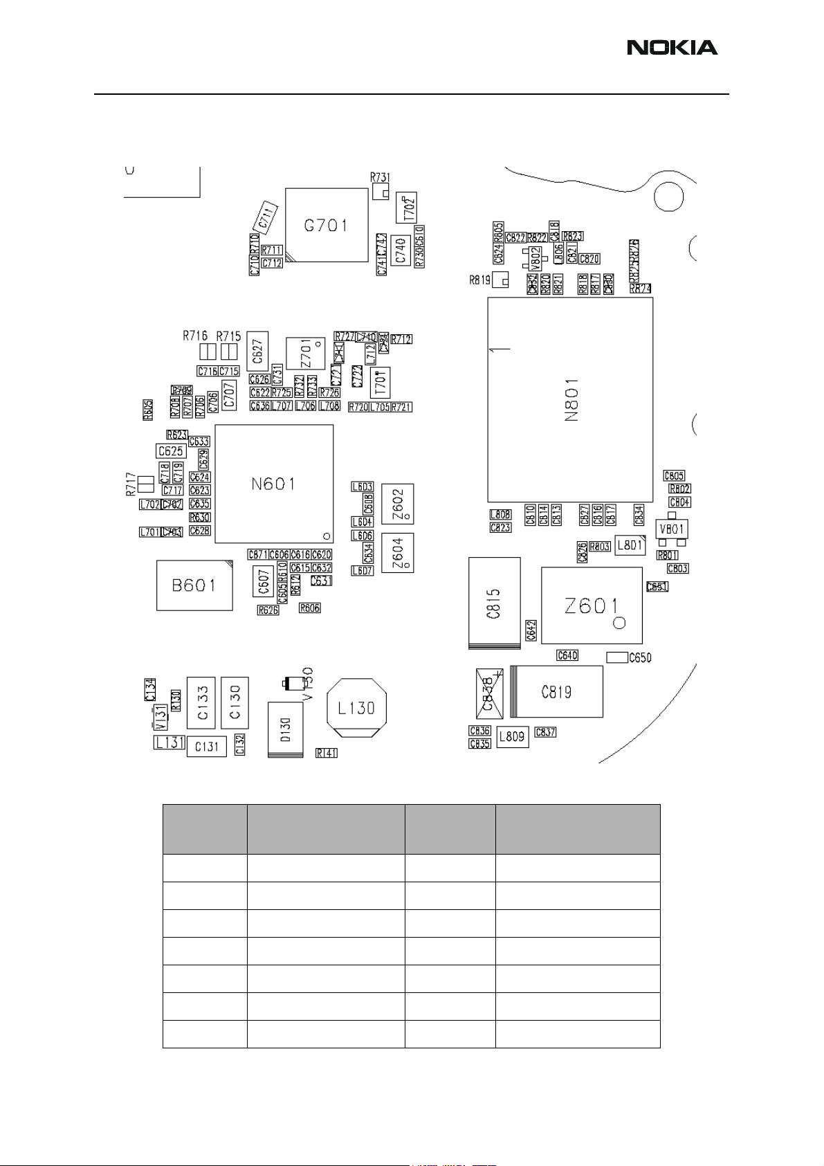
RF Key component placement
Figure 1: RF key component placement
Table 1: Key components
Reference
number
N601 Mjoelner RF ASIC
B601 26 MHz Xtal
Z602 GSM1800 RX SAW
Z604 900 RX SAW filter L801 Directional Coupler
Z701 900 TX SAW filter V801 Detector Diode
T701 GSM1800 TX Balun Z601 Antenna switch
V802 900 TX buffer N801 Power Amplifier
Name
Reference
number
Name
Page 4 Copyright © 2004 Nokia Corporation Issue 1 05/2004
Company Confidential
Page 9
Company Confidential RH-29
Nokia Customer Care 6b - RF Troubleshooting
Reference
number
G701 3.7 GHz VCO
T702 VCO Balun
Name
RF measurement points
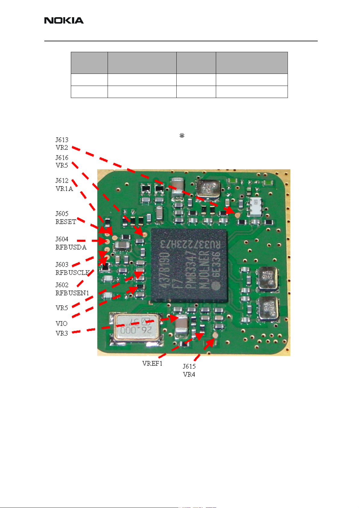
RF supply points
Reference
number
Name
Figure 2: RF Supply points inside Mjoelner can
RF power supplies are generated in the UEM and can be measured either in the Mjoelner
can or in the baseband can. Arrows mark the measurement points inside the pictures.
Issue 1 05/2004 Copyright © 2004 Nokia Corporation Page 5
Company Confidential
Page 10
RH-29 Company Confidential
6b - RF Troubleshooting Nokia Customer Care
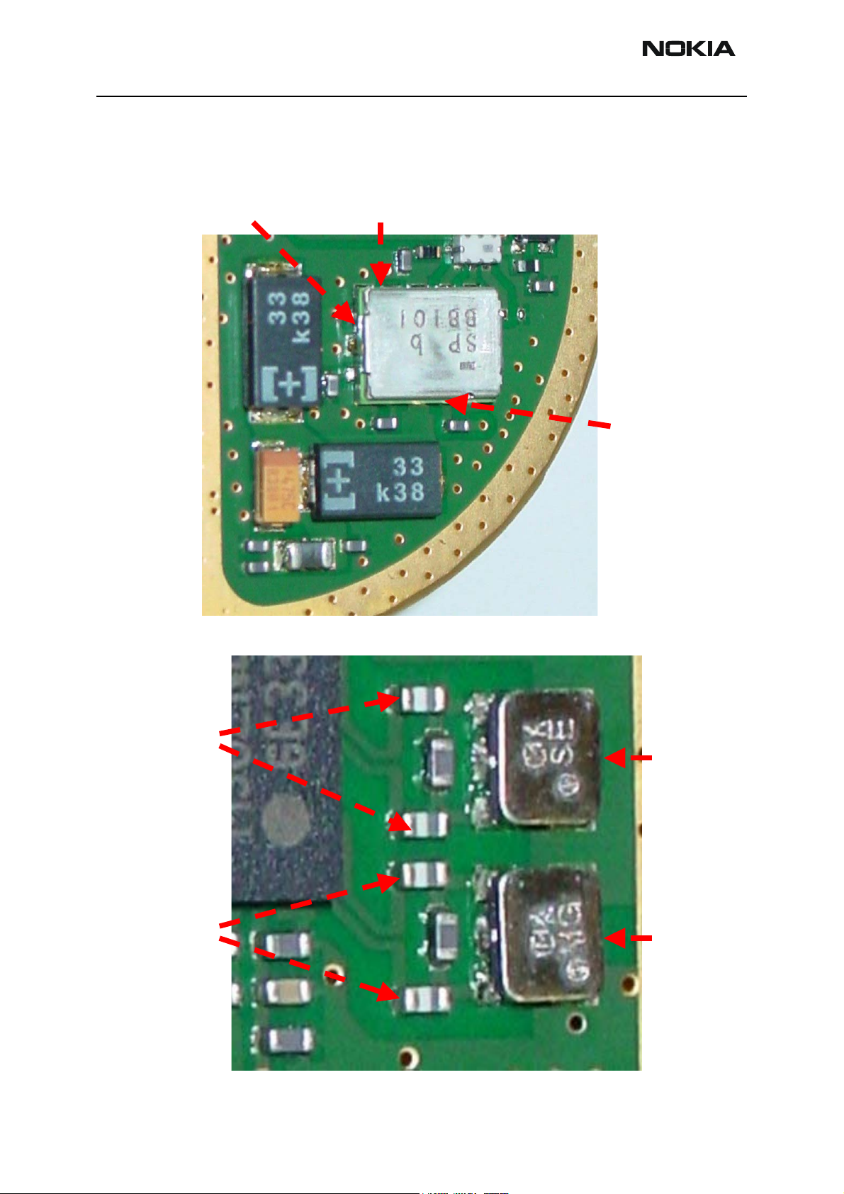
Measurement points in the receiver
Figure 3: Rx measurement points in antenna switch.
GSM900 antenna
switch output
DCS1800 antenna
switch output
Antenna
Switch input
Figure 4: Rx measurement points at Rx SAW filters and Mjoelner RF ASIC
DCS1800 SAW
Output/Mjoelner
Input
GSM900 SAW
Output/Mjoelner
Input
Z602
DCS RX
SAW Input
Z604
GSM RX
SAW Input
Page 6 Copyright © 2004 Nokia Corporation Issue 1 05/2004
Company Confidential
Page 11
Company Confidential RH-29
N
Nokia Customer Care 6b - RF Troubleshooting
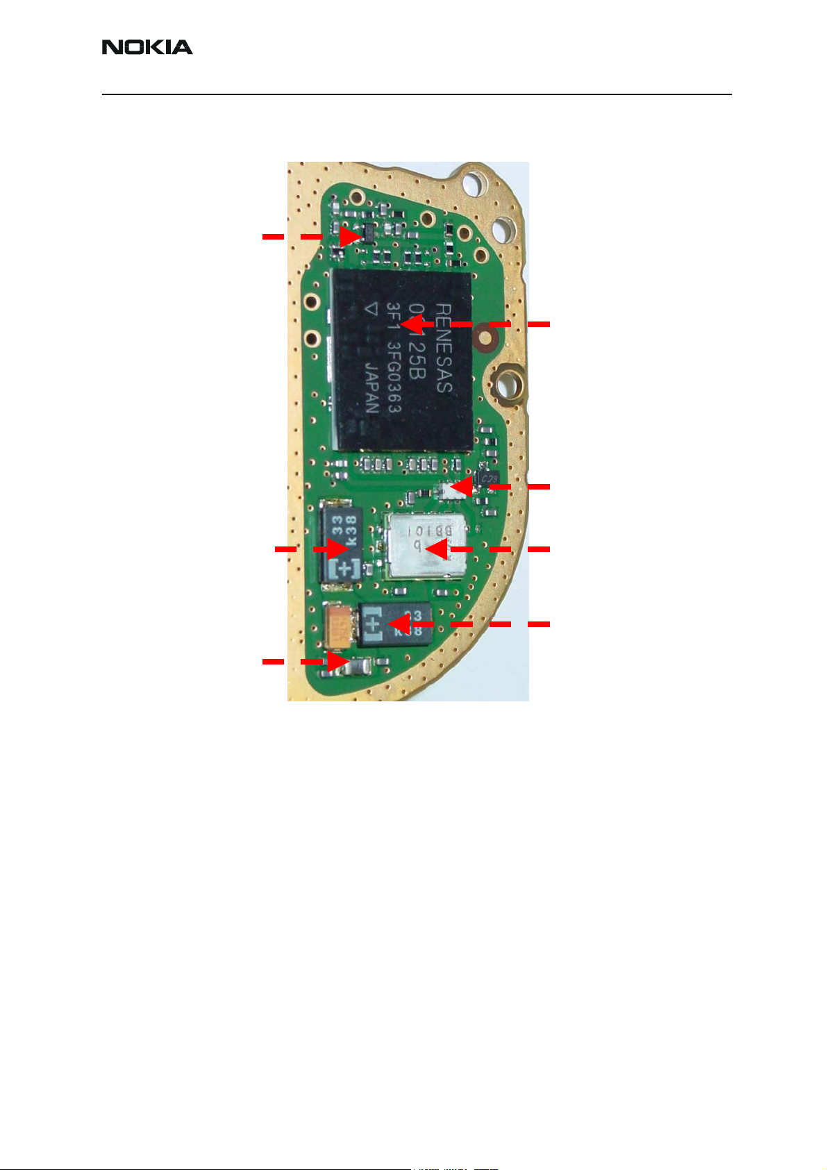
Measurement points in the transmitter
Figure 5: Tx measurement points inside PA can
V802
900 PreAmp
801
Triple
Band PA
V801
Power Detector
C815
Vbat Supply capacitor
L809
Vbat Supply inductor
L801
Coupler
Z601
Antenna
C819
Vbat Supply capacitor
Issue 1 05/2004 Copyright © 2004 Nokia Corporation Page 7
Company Confidential
Page 12
RH-29 Company Confidential
6b - RF Troubleshooting Nokia Customer Care
Figure 6: Tx measurement points for TXC, TXP signals
Page 8 Copyright © 2004 Nokia Corporation Issue 1 05/2004
Company Confidential
Page 13
Company Confidential RH-29
Nokia Customer Care 6b - RF Troubleshooting
Receiver
General instructions for RX troubleshooting
Connect the phone to a PC with DAU-9S cable and dongle and follow the following
instructions:
Measuring RX I/Q signals using RSSI reading
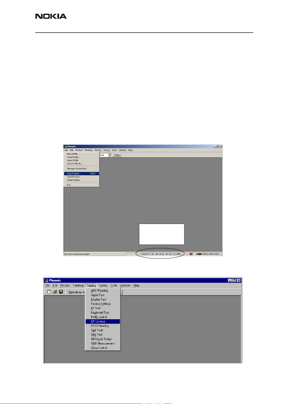
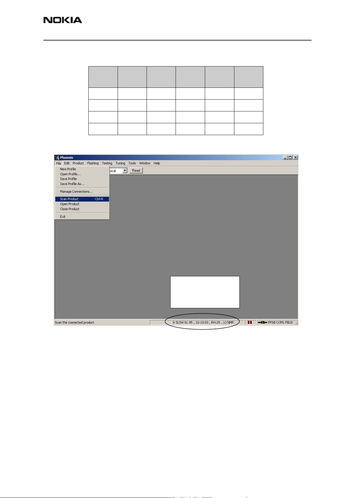
Start Phoenix Service Software
Open the FBUS connection
Select Scan Product Ctrl-R
Wait until phone information shows in the window at the bottom of the screen.
Set operating mode to local mode
Phone information
Product Information
Software version
Issue 1 05/2004 Copyright © 2004 Nokia Corporation Page 9
Company Confidential
Page 14
RH-29 Company Confidential
6b - RF Troubleshooting Nokia Customer Care
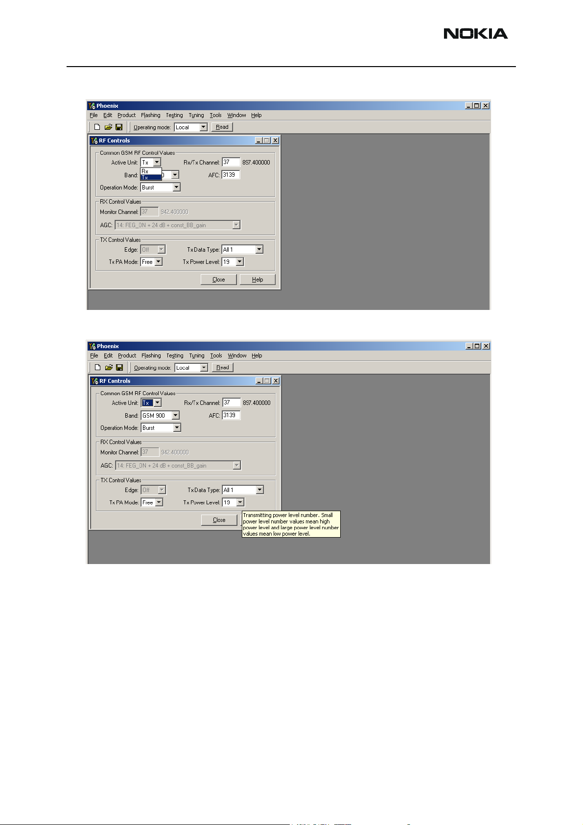
Select Testing Alt-S
RF Controls R
Wait until the RF Controls window pops up
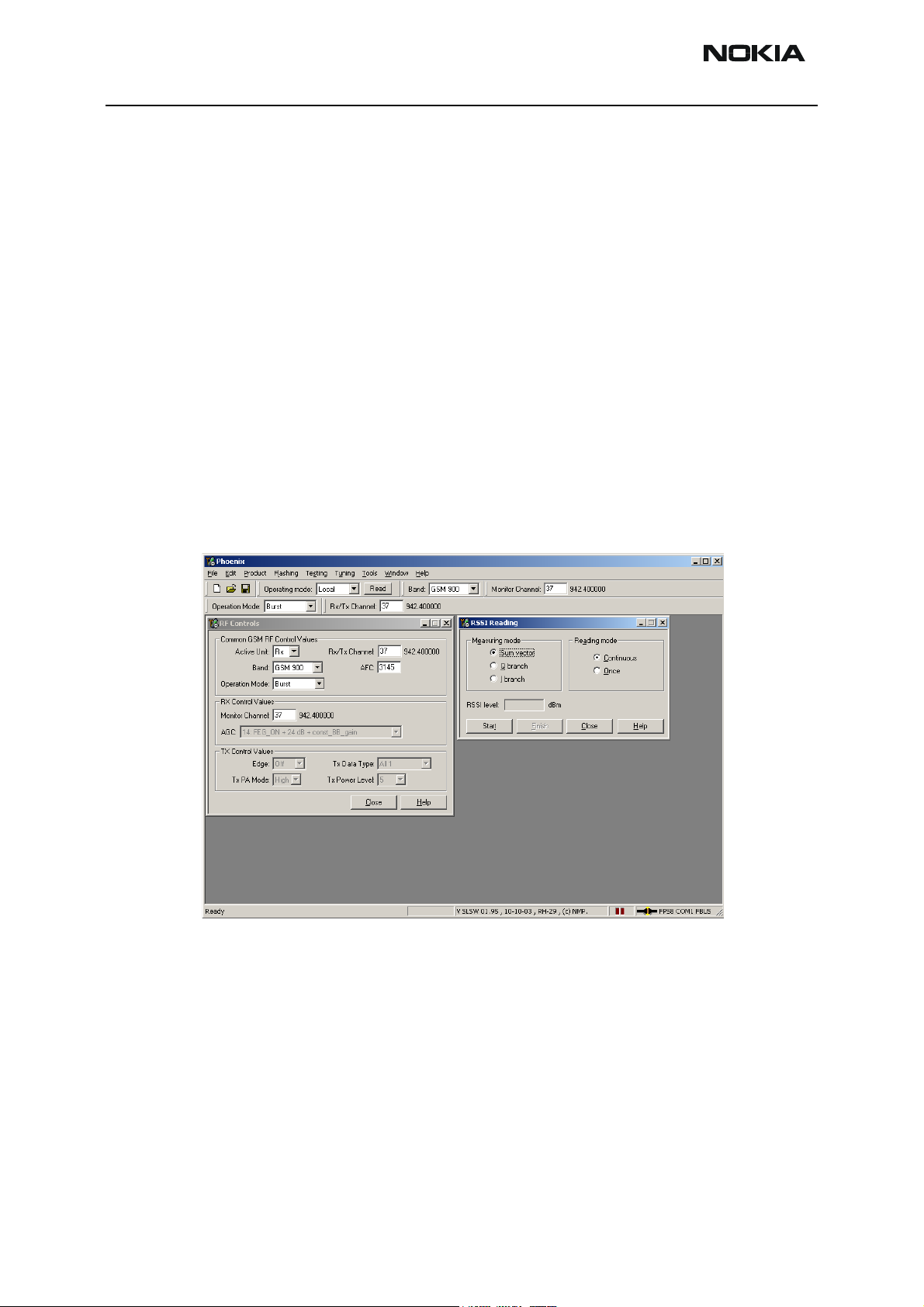
Select Band GSM900 or GSM1800
Active unit RX
Operation mode Burst
RX/TX Channel 37 or 700
Select Testing Alt-S
RSSI reading G
The setup should now look like this:
Apply a signal with a frequency of
EGSM900: 942.467 MHz (channel 37 + 67.710kHz offset)
GSM1800: 1842.867 MHz (channel 700 +67.710kHz offset)
and a power level of -80dBm to the RF-connector (remember to compensate for cable
attenuation).
In RSSI reading click Start.
Page 10 Copyright © 2004 Nokia Corporation Issue 1 05/2004
Company Confidential
Page 15
Company Confidential RH-29
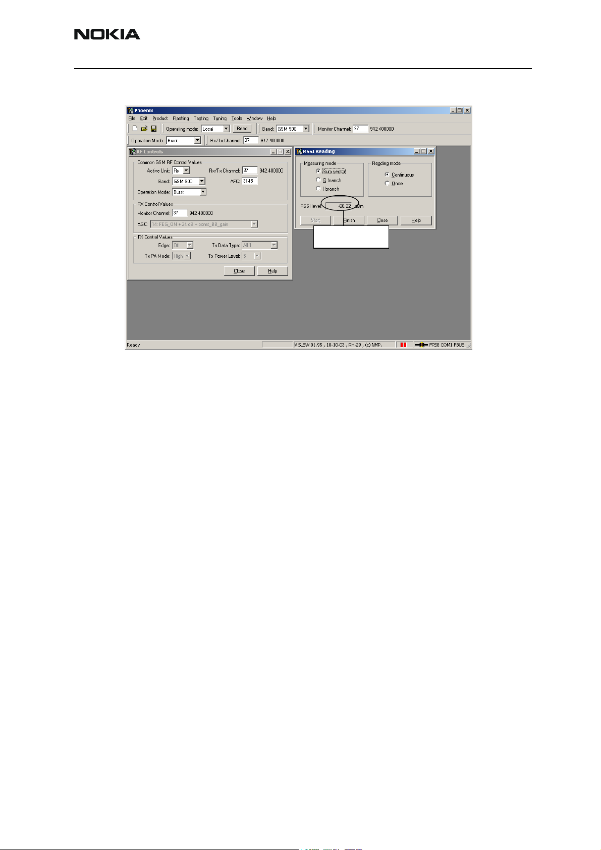
Nokia Customer Care 6b - RF Troubleshooting
The resulting RSSI level should be –80dBm in each band.
RSSI Reading
Measuring RX performance using SNR measurement
Start Phoenix Service Software
Open the FBUS connection
Select Scan Product Ctrl-R
Wait until phone information is shown in the lower window at the bottom of the screen.
Set operating mode to local mode
Select Testing Alt-S
RF Controls R
Wait until the RF Controls window pops up
Select Band GSM 900
Active unit RX
Operation mode Burst
RX/TX Channel 37
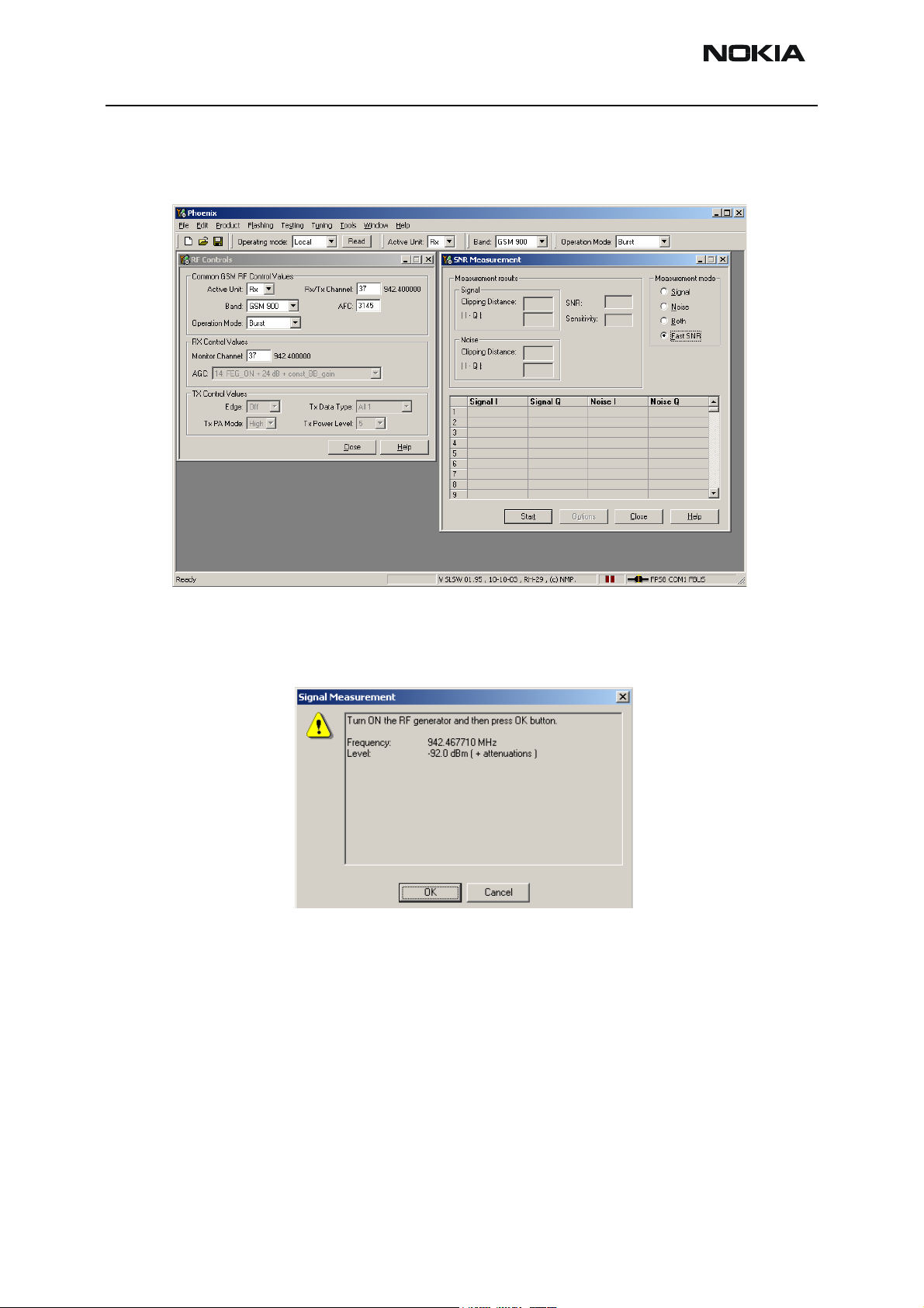
Select Testing Alt-S
SNR Measurement N
Issue 1 05/2004 Copyright © 2004 Nokia Corporation Page 11
Company Confidential
Page 16
RH-29 Company Confidential
6b - RF Troubleshooting Nokia Customer Care
select Fast SNR Radio Button
The setup should now look like this:
Choose respective band (GSM900).
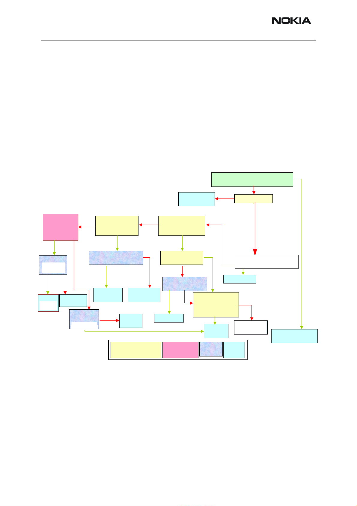
Press Start. A window pops up, e.g. for GSM900 band:
Connect an external signal generator to the RF connector of the phone and set the generator as told in the window, taking care for external cable losses.
Press ok and the window closes.
Read the SNR result. SNR should be: EGSM900 >20dB
GSM1800 >18dB
Measuring front end power levels using spectrum analyzer
Spectrum Analyzer (SA) level values depend on the probe type and should be validated using a good sample.
Page 12 Copyright © 2004 Nokia Corporation Issue 1 05/2004
Company Confidential
Page 17

Company Confidential RH-29
Nokia Customer Care 6b - RF Troubleshooting
The levels that are given here are measured using a resistive probe (50Ohm semi-rigid
cable).
Start Phoenix Service Software
Open the FBUS connection
Select Scan Product Ctrl-R
Wait until phone information shows in the lower right corner of the screen.
Set operating mode to local mode
Select Testing Alt-S
RF Controls R
Wait until the RF Controls window pops up
Select Band GSM 900 or DSC1800
Active unit RX
Operation mode Continuous
RX/TX Channel 37 or 700
Please refer to the troubleshooting chart for proper levels at different test points.
Issue 1 05/2004 Copyright © 2004 Nokia Corporation Page 13
Company Confidential
Page 18
RH-29 Company Confidential
6b - RF Troubleshooting Nokia Customer Care
Receiver troubleshooting
Set up Phoenix as if doing RSSI measurements.
Ascertain which Rx band is faulty.
Refer to Rx troubleshooting flowchart.
Set signal generator frequency to 942.46771MHz for EGSM900 or 1847.86771MHz for
DCS1800.
Set signal generator amplitude to -60dBm.
Select Receive Band
For Testing.
Check Antenna
Switch Cont.
lines. Do they
match the results
in the table?
YES NO
Inspect RF
C650.
Connector.
OK?
YES NO
Replace
Antenna
C650.
Switch
Replace RF
Connector
NO
Check
L701, L702
OK?
L703. OK?
.
YES
Check Antenna
Switch Test Point.
Signal OK?
YES
Check PI Filter & SAW
Components. OK?
YES
Replace
SAW Filter
NO
Replace all 3
Components
Replace
Inductor
KEY
Test With
Spectrum Analyzer
Check SAW
NO
Output / Mjoelner
Input for band. OK?
NO
Measure Vge at
same point. 0.2V?
Inspect PI filter &
SAW for S/c. S/C?
YES
Rectify S/C
Test With
Oscilloscope
Refer to Synth.
Flow Chart.
YES
NO
NO
Check Mjoelner
Voltage Supplies &
RFBUS lines.
All OK?
Check RSSI using Phoenix.
Does it match Sig. Gen Output level?
NO
Is LO Running?
Probe J606-609 for RX I & Q
NO
Does Waveform
NO
YES
look like example?
YES
YES
YES
Probe J211 &
Probe J200 and J202, is
J212. Is digital
data visible?
digital data visible?
YES
Replace UEMReplace UPP
NO
YES
Replace
Mjoelner
Inspect /
Check
Replace
Refer to BB
UEM.
Fault Finding
End
Action
YES
NO
Receiver is working
correctly.
Page 14 Copyright © 2004 Nokia Corporation Issue 1 05/2004
Company Confidential
Page 19

Company Confidential RH-29
Nokia Customer Care 6b - RF Troubleshooting
GSM900 Transmitter
General instructions for GSM900 TX troubleshooting
Apply an RF-cable to the RF-connector to allow the transmitted signal to act normally.
The RF-cable should be connected to measurement equipment (GSM Test equipment,
Power meter, Spectrum Analyzer, or similar). Be sure to use at least a 10-dB attenuator,
otherwise the analyzer may be overloaded.
Connect the phone to a PC with DAU-9P cable and dongle and follow the following
instructions:
Connect the phone to a power supply (3.5... 4V).
Open Phoenix and select Fbus connection.
Select ‘File’ and ‘Scan Product’ from the pull down menus.
Select ‘Testing’, ‘RF controls’ from the pull down menu.
Chose Transmit Band for testing, Use the automatically selected channel.
Set Operation Mode to ‘Burst’.
Choose the Power level you want the phone to operate at.
Set spectrum analyzer center frequency, 897.4MHz for EGSM900 and 1747,8MHz for
DCS1800 and set Span to 1MHz.
Set Amplitude of spectrum analyzer reference level to one that you can clearly see the
transmit pulse according to the kind of test probe you are using.
Diagnose as per troubleshooting flowchart.
Note:Be careful when selecting the operation mode, if ‘Continuous’ is selected prolonged transmission
may damage the phone
TX Path of the transmitted GSM900 signal
For easy error tracing it is important to know the signal path of the GSM900 transmitter.
The components can be grouped into blocks and drawn as shown below. Note that the
following picture shows both GSM900 transmitter (bottom) and GSM1800 transmitter
Issue 1 05/2004 Copyright © 2004 Nokia Corporation Page 15
Company Confidential
Page 20
RH-29 Company Confidential
6b - RF Troubleshooting Nokia Customer Care
(top).
GSM900 TX path of Mjoelner RF ASIC
The balanced TX signal is provided by the base band and is coming to the Mjoelner RF
ASIC. The TX paths of the Mjoelner RF ASIC include mainly two RF modulators for upconversion of the base band signals, one for GSM900 and one for GSM1800. The base
band signal is modulated with the LO signal corresponding to the wanted TX channel.
The GSM TX output of the Mjoelner RF ASIC is a balanced signal.
From the output of the Mjoelner RFASIC the signal is fed through the 900 TX SAW filter
(Balanced to single ended), the 900 MHz buffer, and a 5 dB pad to the PA input.
GSM900 TX path of the Power Amplifier (PA)
The PA GSM900 part has a minimum stable output power of app. 35 dBm. Voltage supply
is coming directly from the Battery connectors.
The GSM900 output is controlled by the power control loop. From the GSM900 output of
the PA the RF signal is fed through the directional coupler (one of the power control loop
components) to the antenna switch.
Antenna Switch (TX/RX switch)
The antenna Switch works as a diplexer for the RX and TX signals. Moreover, it suppresses the TX harmonics generated by the PA. The antenna switch is controlled by the
Mjoelner RF ASIC using the control signals Vcont1 and Vcont2. The following table
Page 16 Copyright © 2004 Nokia Corporation Issue 1 05/2004
Company Confidential
Page 21
Company Confidential RH-29
Nokia Customer Care 6b - RF Troubleshooting
shows the possible different states.
Vcont1
[Volt]
0 0 X
0 0 X
0 2.7 X
2.7 0 X
Vcont2
[Volt]
900 Rx DCS Rx 900 Tx DCS Tx
Phone information
Product Information
Software version
Issue 1 05/2004 Copyright © 2004 Nokia Corporation Page 17
Company Confidential
Page 22
RH-29 Company Confidential
6b - RF Troubleshooting Nokia Customer Care
Page 18 Copyright © 2004 Nokia Corporation Issue 1 05/2004
Company Confidential
Page 23
Company Confidential RH-29
Nokia Customer Care 6b - RF Troubleshooting
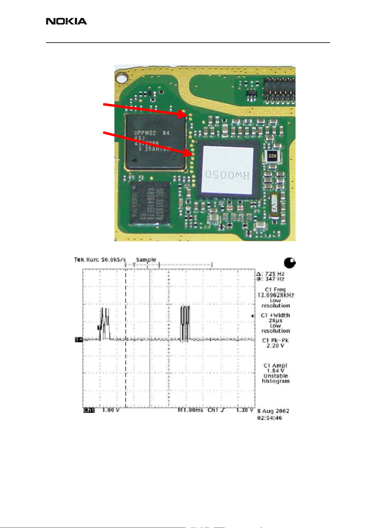
Figure 7: TX Digital I & Q Test Points
J203
TXQD
J202
TXID
Figure 8: TX Digital I & Q Data, J202 and J203
Issue 1 05/2004 Copyright © 2004 Nokia Corporation Page 19
Company Confidential
Page 24

RH-29 Company Confidential
6b - RF Troubleshooting Nokia Customer Care
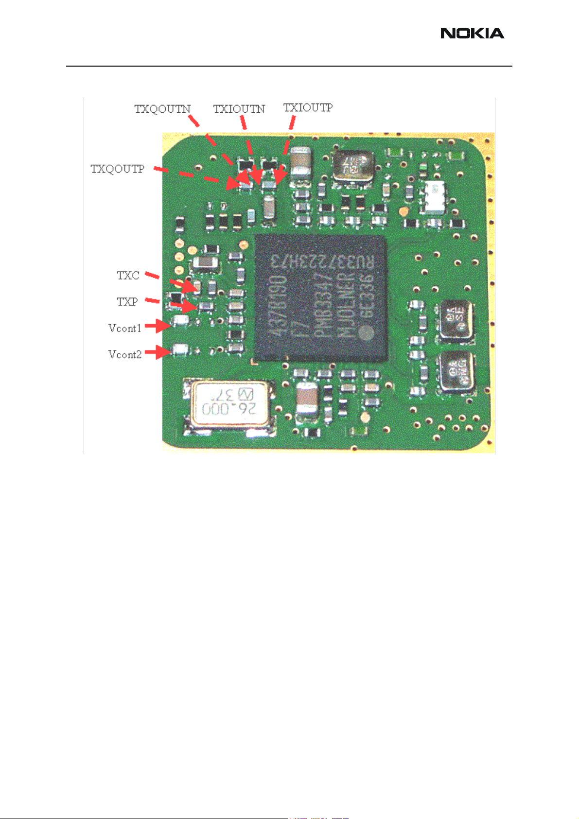
Figure 9: Mjoelner Can Test Points
TXQOUTN
TXQOUTP
TXC
TXP
Vcont1
Vcont2
TXIOUTN
TXIOUTP
TX Analog I & Q Data, C715 & C716
Page 20 Copyright © 2004 Nokia Corporation Issue 1 05/2004
Company Confidential
Page 25

Company Confidential RH-29
Nokia Customer Care 6b - RF Troubleshooting
TXP & TXC Lines during Transmission
TXP
TXC
TXP
TXC
TXP / TXC Mask
Power Control
Loop On
Baseband Generated
Reference for EGSM
Power Level 19
Issue 1 05/2004 Copyright © 2004 Nokia Corporation Page 21
Company Confidential
Page 26

RH-29 Company Confidential
6b - RF Troubleshooting Nokia Customer Care
Figure 10: GSM900 TX Test Points
Vbat
Vbat
DCS In
GSM In DCS In
VTXB_900 (EGSM V802 Pre-Amp Biasing Waveform)
VTXB_900 (900 V802 Pre-Amp Biasing Waveform)
Only Biases V802 for
duration of TX Pulse.
Page 22 Copyright © 2004 Nokia Corporation Issue 1 05/2004
Company Confidential
Page 27

Company Confidential RH-29
Nokia Customer Care 6b - RF Troubleshooting
Figure 11: 900 Tx waveform, burst, pwr level 19
Figure 12: 900 Tx waveform, continuous, pwr level 19
Issue 1 05/2004 Copyright © 2004 Nokia Corporation Page 23
Company Confidential
Page 28

RH-29 Company Confidential
6b - RF Troubleshooting Nokia Customer Care
Page 24 Copyright © 2004 Nokia Corporation Issue 1 05/2004
Company Confidential
Page 29

Company Confidential RH-29
900
Nokia Customer Care 6b - RF Troubleshooting
900 Tx troubleshooting flowchart
THE FIRST FLOW DIAGRAM ASSUMES THE FOLLOWING:
• Phoenix has been set up as shown in the following screen (the Tx
power level may be increased using Phoenix if it makes the Tx pulse
easier to see).
• Relevant components have been visually inspected for orientation,
placement, etc.
• The transmit signal has been checked with a spectrum analyzer at RF
connector, X602 and was found to be too low or non-existent.
• The VCO is running correctly.
• The power amplifier is getting a correct VBATRF supply via L809.
Change
L801
Is Signal at
Antenna pin
of Z601 ok?
Change X602
RF Connector
YES
Change
Antenna
Switch
• Mjoelner’s supply voltages VR1A, VR2, VR3, VR4, VR5 & VR7 are all
Is Signal at
Is Signal at
TX_GSM on
TX_850_OUT
L801 OK?
on L801 OK?
YES
C650.
Check Antenna
Switch Control
Lines. Do they
match the results
in the table?
Check L701
Check L701,
Check L703
and L702.
L702 & L703.
and L813 OK?
OK?
OK?
working correctly.
Is Signal
Is Signal
at C834
900
YES
NO
NO
NO
at C881
OK?
OK?
Probe VPD_850 Signal
Probe VPD_900Signal
on R818 and set Power
on R818 and set Power
Level to 19 using Phoenix.
Level to 19 using Phoenix.
Is Pulse Pk-Pk 2.8V?
Is Pulse Pk-Pk 2.8V?
NO
YES
NO
900
START
START
YESYESNO NO NO
YES
900
Is 850
Is EGSM
TXIN signal
TXIN signal
R825
at R805 OK?
at R828 OK?
NO
YES
Is Signal at V802
Collector OK?
Is Signal at
Is Signal at
C733 OK?
R733 OK?
Is signal at
R805
L807 OK?
YES NO
NO
Is VTXB
Is VTXB
_850 OK?
_900 OK?
NO
YES
YES
Are TX I & Q on
C715 & C716. OK?
YES
Are TXP &
TXC visible?
YES
NO
TXP
Is VR2
2.8V on
C731?
NO YES
NO
TXC
Replace PA
Check / Replace
Check / Replace
R825, R824 and
R826,R827,R828,
R805, C820, C821
R826.
C820,C821
Check Z701 &
Biasing components
Check V802 &
associated components
Change
Mjoelner
Are digital I & Q
signals OK on
J202 and J203?
J123 & J214?
YES
NO
Change
UPP
Change
UEM
Replace
Inductors
KEY
Test using
Spectrum Analyzer
Test using
Oscilloscope
Check /
Inspect
End
Action
Issue 1 05/2004 Copyright © 2004 Nokia Corporation Page 1
Company Confidential
Page 30

RH-29 Company Confidential
6b - RF Troubleshooting Nokia Customer Care
GSM1800 Transmitter
General instructions for GSM1800 TX troubleshooting
Apply an RF-cable to the RF-connector to allow the transmitted signal to act as normal.
RF-cable should be connected to measurement equipment (GSM Test equipment, Power
meter, Spectrum Analyzer, or similar).
DCS1800 Tx troubleshooting flowchart
The following diagram assumes the following:
• Phoenix has been set up as shown previously (selecting DCS1800 in
the RF control box).
• Relevant components have been visually inspected for orientation,
placement etc.
• The Transmit Signal has been checked with a S pectrum Analyzer at the
RF connector, X602 and was found to be low or non-existent.
• The VCO is running correctly.
• The Power Amplifier is getting a correct VBATRF supply via L809.
• Mjoelner’s supply voltages VR1A, VR2, VR3, VR4, VR5 & VR7 are all
working correctly.
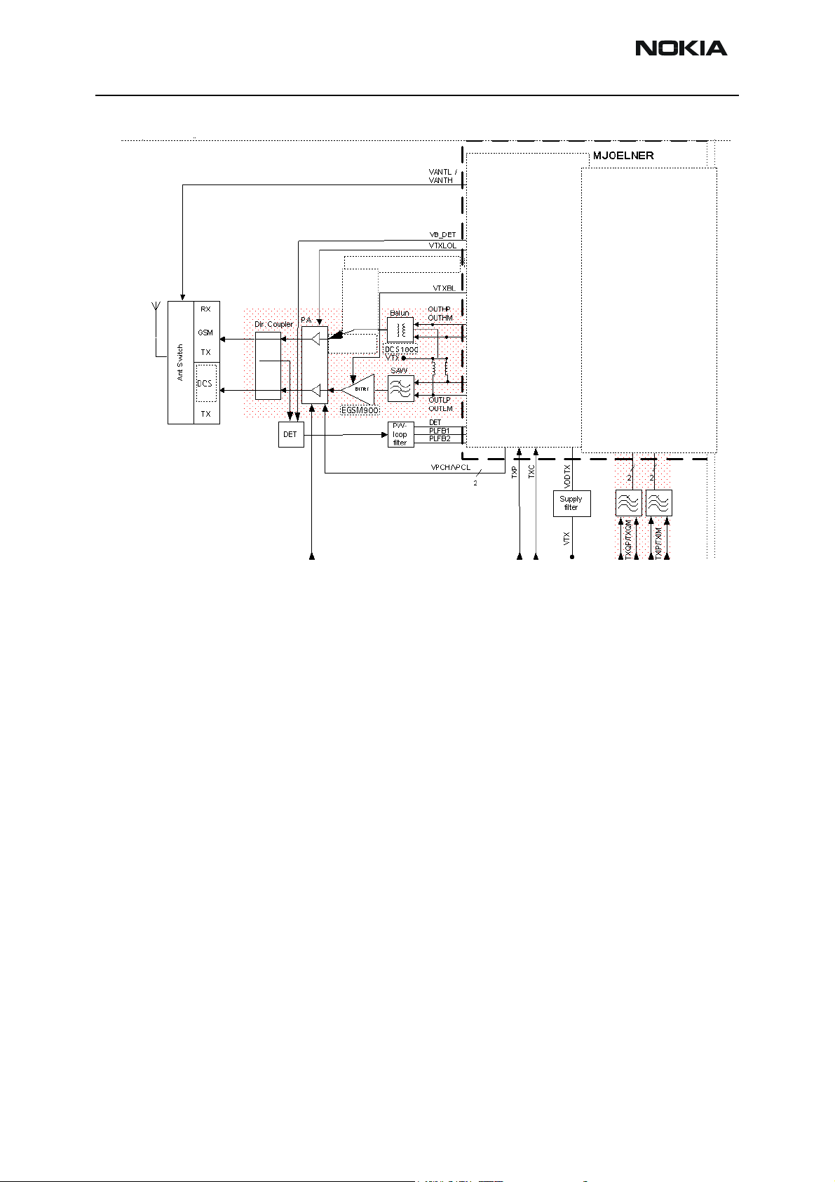
Path of the transmitted 1800 signal
For easy error tracking it is important to know the signal path of the GSM1800 transmitter. The components can be grouped into blocks and drawn as shown below. Note that
the picture shows both EGSM900 transmitter (bottom) and GSM1800 transmitter (top).
Page 2 Copyright © 2004 Nokia Corporation Issue 1 05/2004
Company Confidential
Page 31

Company Confidential RH-29
0
Nokia Customer Care 6b - RF Troubleshooting
MJOELNER
VANTL /
VANTH
RF
Controls
VDDDIG
2
2
TXQP/TXQM
1/4
2
TXIP/TXIM
VB_DET
VTXLOL
VTXBH
VTXBL
RX
GSM
TX
RX
Ant Switch
DCS
PCS
TX
Dir. Coupler
DET
VBATTRF
PA
Buffer
PCS
Buffer
GSM850
EGSM900
DCS180
VTX
Balun
SAW
PWloop
filter
OUTHP
OUTHM
OUTLP
OUTLM
DET
PLFB1
PLFB2
VPCH/VPCL
RF
Controls
Open collector
Open collector
2
TXP
PWC
TXP
TXC
TXC
VDDRXBB
VDDTX
Supply
filter
VTX
VR2
1/2
2
2
2
The path of Mjoelner RF ASIC
The balanced TX signal from base band is coming to Mjoelner RF ASIC. The GSM1800
path includes a RF modulator for GSM1800. The BB signal is up-converted with the LO
signal corresponding to the wanted TX channel. The GSM1800 TX output of Mjoelner is a
balanced signal.
From the output of Mjoelner the signal is fed through the Balun T701 (Balanced to single
ended) and a 3 dB pad.
The path of the PA
The GSM1800 part of the PA has a maximum output of approximately 33dBm. The supply is coming directly from the Battery connectors.
The output is controlled by the power control loop. From the output of the PA the signal
goes through the directional coupler (one of the power control loop components) to the
Antenna Switch.
Issue 1 05/2004 Copyright © 2004 Nokia Corporation Page 3
Company Confidential
Page 32

RH-29 Company Confidential
6b - RF Troubleshooting Nokia Customer Care
Antenna Switch
The Antenna Switch works as a diplexer between RX and TX Bands. Moreover, it partly
suppresses the harmonics generated by the PA. Mjoelner RF ASIC controls the antenna
switch by two voltages Vcont1 and Vcont2. The following table shows the different
states.
Z604 input
EGSM900
Vcont2
Vcont1
[Volt]
0 0 X
0 0 X
0 2.7 X
2.7 0 X
Vcont2
[Volt]
Figure 13: Antenna Switch Test Points
EGSM
RX
Z602 input
DCS RX
Vcont1
EGSM
TX
DCS1800 RX
DCS TX
Antenna
Switch input
Page 4 Copyright © 2004 Nokia Corporation Issue 1 05/2004
Company Confidential
Page 33

Company Confidential RH-29
Nokia Customer Care 6b - RF Troubleshooting
Troubleshooting chart for GSM1800 transmitter
Is signal at
DCS
DCS / PCS
Input of Z601
OK?
Replace
L801
Are Z601
Control lines
as per table?
YES
Check RF
Check
Connector
C650.
X602. OK?
NO
Replace RF
C650.
Connector.
NO
NOYES
YES
Is signal on
C823 OK?
Is VPD_1800
signal OK?
Investigate
Mjoelner
Replace
Antenna
Switch
KEY
Test With
Spectrum
Analyzer
NO
NO
Test With
Oscilloscope
YES
YES
Replace PA
START
START
Is TX Signal at
Is TX Signal at
DCS / PCS In on
DCS In on
L812 OK?
R819 OK?
YES
Are TXP &
TXC OK?
TXC
U/S
Change
UEM
Check /
Inspect
NOYES
TXP
U/S
Change
UPP
End
Action
Is TX Signal
at L705 OK?
NO
Are TX I & Q
Signals OK?
YES
NO
Are Digital
I & Q Signals
J202
OK at J213 &
and J203?
J214
NO YES
YES
Is Vr2 2.8V
on R720?
NO YES
Check T701
& Associated
Components.
Refer To Baseband
Fault Finding
If the Tx output is too high, then it is most likely that there is a problem within the Power
Control loop.
Mjoelner is receiving the Reference TXC from Baseband and not getting any feedback
from DET to compare with TXC. The result is that Mjoelner drives VDP_900/VPD_1800
high to try and increase the power output so that the DET signal is matching TXC. With a
break in the Power Control loop, the DET signal never reaches Mjoelner so it assumes
that the PA is not outputting enough power so it tries to compensate by increasing the
gain.
When checking the Power Control loop, make sure that VBD is pulsing at 2.8V Peak to
Peak. Check the DET pulse at Mjoelner input on R706.
Issue 1 05/2004 Copyright © 2004 Nokia Corporation Page 5
Company Confidential
Page 34

RH-29 Company Confidential
6b - RF Troubleshooting Nokia Customer Care
This case is the same for EGSM900 & DCS1800.
NO YES
Replace Faulty
Components
Are R706, R707
& R708 OK?
Eunsure that VBD
is pulsing 2.8V
Pk - PK and
investigate Mjoelner
KEY
Test With
Spectrum
Analyzer
Is DET Pulse
on C805 OK?
Test With
Oscilloscope
Replace
V801
Check /
Inspect
NOYES
NO
End
Action
Is RF Signal
at V801 OK?
YES
Is DET Pulse
on C804 OK?
NO
YES
Replace
L801
Replace
R802
Page 6 Copyright © 2004 Nokia Corporation Issue 1 05/2004
Company Confidential
Page 35

Company Confidential RH-29
Nokia Customer Care 6b - RF Troubleshooting
RH-29 Synthesizer
There is only one PLL synthesizer generating frequencies for both Rx and Tx for all three
bands. VCO frequency is divided by 2 or by 4 in Mjoelner depending on which band is
active.
General instructions for synthesizer troubleshooting
Connect the phone to a PC with DAU-9P cable and dongle and follow these instructions:
Start Phoenix Service Software (dongle needed):
Select Scan Product Ctrl-R
Wait until phone information shows in the lower right corner of the screen.
Set operating mode to local mode.
Start RF Control window:
Select Testing Alt-S
RF Controls R
Wait until the RF Controls window pops up
Set the synthesizer to the following mode:
Select Band GSM900 or DCS1800
Active unit RX
Operation mode Continuous
RX/TX Channel 37 or 700
Issue 1 05/2004 Copyright © 2004 Nokia Corporation Page 7
Company Confidential
Page 36

RH-29 Company Confidential
6b - RF Troubleshooting Nokia Customer Care
The setup should now look like this:
It is possible to measure frequency of 3769,6MHz at the output of the VCO (G701) using
a resistive probe and a spectrum analyzer. It is possible to measure tuning voltage at
charge pump output (C710) easily. For f
= 3526.4MHz the tuning voltage should be
VCO
2.3VDC. 2.8VDC (Tuning sensitivity of VCO is 240MHz/V typ.).
Figure 14: PLL Synthesizer Test Points
T702
VR7
2.8V
Input
T702
VCO
Out
Balanced
Output
VC
0V - 4.7V
Charge Pump
O/p Test Point
If this is not the case, then go to troubleshooting chart in this document for trouble-
Page 8 Copyright © 2004 Nokia Corporation Issue 1 05/2004
Company Confidential
Page 37

Company Confidential RH-29
Nokia Customer Care 6b - RF Troubleshooting
shooting.
Figure 15: Mjoelner Can Test Points
J612
VR1A
4.75V
VR5
2.8V
VIO
1.8V
VR3
2.8V
VREF1
1.35V
26 MHz reference oscillator (VCXO)
The 26 MHz reference oscillator (VCXO) is part of Mjoelner RF-ASIC (N601). It needs only
an external 26 MHz Xtal (B601) as external circuitry.
The reference oscillator has three functions:
• Reference frequency for the PLL synthesizer .
• System clock for BB (RFClk_I = 26 MHz).
• 26 MHz Reference clock (LPRFClk_I) for Bluetooth Module (N430) via
buffer V601.
For an error free initial synchronization, the 26MHz frequency of the VCXO must be
accurate enough. Therefore, a VCXO-calibration (cal) value is written via the serial Bus
into the RefOSCCAL register of Mjoelner and an additional bit in the RefOSCCntl register
of the Mjoelner. That is necessary for the rough calibration of the VCXO.
Issue 1 05/2004 Copyright © 2004 Nokia Corporation Page 9
Company Confidential
Page 38

RH-29 Company Confidential
6b - RF Troubleshooting Nokia Customer Care
The VCXO is fine tuned by programming the AFC value via the serial bus of Mjoelner. The
necessary AFC value is written into the RefOSCAFC register in Mjoelner.
VCO
The VCO is able to generate frequencies in the range from 3420MHz to 3840MHz when
PLL is in function. The frequency of the VCO signal is divided by 2 or by 4 in Mjoelner RFASIC. So it is possible to generate the frequency of all channels in GSM900 and
GSM1800 (both RX and TX). Frequency of the VCO is controlled by DC voltage (Vc) coming from the PLL loop filter. Range of Vc when PLL is in function is 0.7V– 3.8V. Typical
tuning sensitivity of the VCO is 250MHz/V. Even if PLL is not working (Vc out of range)
there is a frequency at the output of the VCO, which is between 3 and 4 GHz (if the VCO
itself is ok).
troubleshooting chart for PLL Synthesizer
Set up Phoenix RF Controls
Band: GSM 900
900
Mode: RX Continuous
Channel: 37
Change Channel
to 975. Does LO
124.
change frequency?
37
190
YES NO
YES
NO
3769.6MHz
Check T702
Balanced O/P.
Signal same?
Check T702 I/P.
LO Present?
YES NO
Change
T702
PLL is working
Is LO@
3.77 GHz
NO
Change
R731
START
YES
Check VCO Out.
Is LO visible?
YES
YES NO
Does the VC
Vge change
when you change
channels?
YES
Check Loop Filter
Components. OK?
NO
KEY
Test with
Spectrum
Analyzer
NOYES
Check Mjoelner Voltage Supplies
VR1A, VIO, VR3, VREF1. OK?
Test with
Oscilloscope
Check VR7 VCO
Side of R730.
Vge OK?
Replace G701
YES
YES
Replace Mjoelner
Replace Faulty Loop
Filter Components
Check /
Inspect
NO
NO
Refer to BB
Fault Finding
End
Action
Check VR7 J618.
Vge OK?
NO
YES
Change
R730
It is important to say that power supply for VCXO (VR3) is only switched ‘OFF’ in the socalled ‘Deep Sleep Mode’ and power supply for VCO (G701 VR7) is switched ‘OFF’ in socalled ‘Sleep Mode’.
Page 10 Copyright © 2004 Nokia Corporation Issue 1 05/2004
Company Confidential
Page 39

Company Confidential RH-29
Nokia Customer Care 6b - RF Troubleshooting
PLL power supply
Loop Filter
VCO and power supply
Issue 1 05/2004 Copyright © 2004 Nokia Corporation Page 11
Company Confidential
Page 40

RH-29 Company Confidential
6b - RF Troubleshooting Nokia Customer Care
26MHz Bluetooth buffer
Antenna
Instructions for antenna troubleshooting
If the TX, RX or SX troubleshootings does not solve RF failure, do the following tests:
Use DA-17 jig and phone in 'local' mode. Use Phoenix to control the phone.
Set TX on and check the output power on low, middle and high channels. If the power
levels are not OK, check the antenna, antenna connection pads and antenna pins. If there
are big differencies (> 5 dB) between channels, change the antenna. If the levels are OK,
the failure reason is bended center shield or in other part of the phone. Change the
shield and try again. If it is still not functional, refer to BB troubleshooting.
Set RX on, connect signal generator to DA-17 and start RSSI testing. Check the RSSI levels on low, middle and high channels. If the RSSI levels are not OK, check the antenna,
antenna connection pads and antenna pins. If there are big differencies (> 5 dB) between
channels, change the antenna. If the RSSI levels are OK, the failure reason is bended center shield or in other part of the phone. Change the shield and try again. If it is still not
functional, refer to BB troubleshooting.
Page 12 Copyright © 2004 Nokia Corporation Issue 1 05/2004
Company Confidential
Page 41

Company Confidential RH-29
Nokia Customer Care 6b - RF Troubleshooting
Phoenix Tuning
Connect the phone to a PC running the Phoenix Service Software.
Start Phoenix Service Software and open FBUS connection
Select File Scan Product
Wait until phone information is shown in the lower right corner of the screen.
RF tuning after repairs
Different repairs require different tuning. In general it is necessary to determine in which
section the repair was done to select which tunings to perform. To determine if RF tuning
is necessary after repair it is important that the functionality of the repaired circuit is
understood well. It is recommended to perform complete RF tuning if RF is repaired.
• In general repairs in the TX part will require "TX Power Level Tuning"
and "TX IQ Tuning".
• In general repairs in the RX part or PLL part always require "RX Calibration", “Rx Band Filter Response Calibration”.
• If Mjoelner is changed all calibrations have to be done.
Other parts interfacing to TX, RX or PLL might require tuning, but common sense should
be used, e.g. if a component that has no influence on RF performance has been changed,
e.g. the microphone, on/off key, mechanical parts or similar, there is no need to do any RF
tuning.
RX channel select filter calibration
This calibration is calibrating the Base band filter inside Mjoelner. It is done by internally
measuring a prototype filter, for this reason the calibration is done once, not separately
in 2 bands.
Set operating mode to local mode
Select Tuning Alt-U
RX Channel Select filter Calibration F
Issue 1 05/2004 Copyright © 2004 Nokia Corporation Page 13
Company Confidential
Page 42

RH-29 Company Confidential
6b - RF Troubleshooting Nokia Customer Care
The setup should now look like this:
Press Tune and the optimal values are found.
Make sure that Save to Phone is active. It can be activated by clicking with mouse or by
pressing the letter v.
Press Stop and the RX Channel Select Filter Calibration is finished. You can now leave the
tuning by closing the window.
RX calibration (incl. VCXO Calibration)
The "RX calibration" is used to determine gain at different gain-settings for front-end
and Mjoelner and needs to be done in both bands.
RX-calibration requires an external signal generator.
RX-calibration in EGSM900 combines two tunings, VCXO-calibration and AGC-calibration:
Calibration of GSM1800 band only determines AGC values.
The VCXO-calibration finds out a calibration value for VCXO control, an AFC initial
value and 3 AFC-slope coefficients.
A value (RF_TEMP), which represents the RF hardware temperature, is determined during
RX Calibration. This temperature value is used by DSP to RSSI reporting in Normal mode
Page 14 Copyright © 2004 Nokia Corporation Issue 1 05/2004
Company Confidential
Page 43

Company Confidential RH-29
Nokia Customer Care 6b - RF Troubleshooting
of the phone. It is not visible in the calibration process.
AGC-calibration:
The AGC-calibration finds the gain values of the RX-gain system.
The AGC consists of RF LNA, which can be either on or off (gain difference between on
and off state is nominally 30dB) and BB gain which can be controlled in 6dB steps. This
gives 15 gain steps RSSI0 to RSSI14. LNA is off for steps RSSI0 to RSSI4.
AGC-calibration measures the gain at gain step RSSI4 and RSSI7. The other gain values
are calculated.
VCXO-calibration:
The VCXO-calibration ensures the function of an initial synchronization (before location
update is done) when the mobile station is in Normal mode. For an error free initial synchronization, the 26MHz frequency of the VCXO must be accurate enough. Therefore, a
VCXO cal value is written into the RefOSCCAL register of the Mjoelner.
During VCXO-calibration, the VCXO cal value is changed by a DSP-algorithm until a synchronization is possible. This means the VCXO oscillates at 26 MHz with a sufficient minimum frequency error.
To further minimize the frequency error, an initial AFC value is determined by the DSP
and written into RefOSCAFC register of the Mjoelner.
Also the DSP algorithm determines 3 AFC slope coefficients Slope C1...3 during VCXO
calibration. One AFC slope value is not sufficient for Mjoelner F3, because the AFC slope
is non-linear in this chip.
EGSM900 and DCS1800
Select Tuning Alt-U
Wait until the RX Calibration window pops up.
Select Band GSM900
RX Calibration C
Issue 1 05/2004 Copyright © 2004 Nokia Corporation Page 15
Company Confidential
Page 44

RH-29 Company Confidential
6b - RF Troubleshooting Nokia Customer Care
The setup should now look like this:
Press Start and a new window pops up:
Connect an external signal generator to the RF connector of the phone and set the generator as told in the window, taking care for external cable losses.
Press OK and the window closes.
Page 16 Copyright © 2004 Nokia Corporation Issue 1 05/2004
Company Confidential
Page 45

Company Confidential RH-29
Nokia Customer Care 6b - RF Troubleshooting
A typical result will look like this:
The EGSM900 has been tuned. To proceed to DCS1800 tuning, press Save & Continue
and a new window pops up::
Let an external signal generator be connected to the RF connector of the phone and set
the generator as told in the window, taking care of external cable losses.
Press OK and the window closes.
Issue 1 05/2004 Copyright © 2004 Nokia Corporation Page 17
Company Confidential
Page 46

RH-29 Company Confidential
6b - RF Troubleshooting Nokia Customer Care
A typical result will look like this:
Press Save and Continue, and a new window pops up:
Press OK and the RX Calibration of the EGSM900 and DCS1800 are finished.
Page 18 Copyright © 2004 Nokia Corporation Issue 1 05/2004
Company Confidential
Page 47

Company Confidential RH-29
Nokia Customer Care 6b - RF Troubleshooting
RX AGC limits
The Rx calibration is only valid if it is within certain limits.
For the most recent limits see RH-29 Production Testing Requirements,
If calibration is not within limits, there is a fault in the RX chain.
Below the values for RSSI4 and RSSI7 are given:
RSSI4:
Table 2:
band min typ max
EGSM900 81 86 91
DCS1800 79 85 89
RSSI7:
Table 3:
band min typ max
EGSM900 103 108 11 3
DCS1800 100 104 110
RX band filter response compensation
EGSM900 and DCS1800
Set operating mode to local mode
Select Tuning Alt-u
RX Band Filter Response Compensation B
Select Band EGSM900
Issue 1 05/2004 Copyright © 2004 Nokia Corporation Page 19
Company Confidential
Page 48

RH-29 Company Confidential
6b - RF Troubleshooting Nokia Customer Care
The setup should now look like this:
Select Input Signal Level -60dBm
Manual tuning
Press Manual tuning and a window pops up:
Connect an external signal generator to the RF connector of the phone and set the generator as told in the window.
Page 20 Copyright © 2004 Nokia Corporation Issue 1 05/2004
Company Confidential
Page 49

Company Confidential RH-29
Nokia Customer Care 6b - RF Troubleshooting
Press OK and a new window pops up:
Set the generator as told in the window.
Press OK and a new window pops up. Repeat this sequence 9 times until all channels are
done.
A typical result will look like this:
The EGSM900 has been tuned. Press Save and Continue to proceed to DCS1800 tuning.
Issue 1 05/2004 Copyright © 2004 Nokia Corporation Page 21
Company Confidential
Page 50

RH-29 Company Confidential
6b - RF Troubleshooting Nokia Customer Care
A window pops up:
Let the external signal generator be connected to the RF connector and set the generator
as told in the window, taking care of external cable losses. Press OK and the following
window pops up:
Set the generator as told in the window.
Press OK and a new window pops up. Repeat this sequence 9 times until all channels are
done.
Page 22 Copyright © 2004 Nokia Corporation Issue 1 05/2004
Company Confidential
Page 51

Company Confidential RH-29
Nokia Customer Care 6b - RF Troubleshooting
A typical result will look like this:
Select Input Signal Level -60dBm
The DCS1800 has been tuned. Press Save and Continue to finish the tuning. A new window pops up:
Issue 1 05/2004 Copyright © 2004 Nokia Corporation Page 23
Company Confidential
Page 52

RH-29 Company Confidential
6b - RF Troubleshooting Nokia Customer Care
TX I/Q tuning
This tuning must be done in both bands.
EGSM900
Caution: In case you use a spectrum analyser make sure that the external attenuation (20 - 30dB)
between phone and spectrum analyser is high enough that the input of the analyser can’t be destroyed.
Adjust the reference level offset according to the insertion loss from the phone to the spectrum analyser.
PC/Phone operation:
Set operating mode to local mode
Select Tuning Alt-u
TX IQ Tuning I
Wait until the TX IQ Tuning window pops up.
Select Testing Alt-s
RF Controls R
Wait until the RF Controls window pops up.
Connect a Spectrum Analyzer or GSM tester with the option *Narrow Spectrum' to the
RF connector of the phone.
If a spectrum analyzer is used then use the following settings.
Table 4:
EGSM900
Center Frequency 897.4 MHz
Frequency Span 200 kHz
Resolution Bandwidth 3kHz
Video Bandwidth 3kHz
Sweep Time 3 sec.
Sweep Type Clear/Write
Detector Type Max Peak
Reference level 35 dBm
Marker 1 897.33229 MHz
Marker 2 897.4 MHz
Marker 3 897.46771 MHz
Page 24 Copyright © 2004 Nokia Corporation Issue 1 05/2004
Company Confidential
Page 53

Company Confidential RH-29
Nokia Customer Care 6b - RF Troubleshooting
Select in the RF Controls Window:
Select Band GSM900
Active Unit TX
Operation Mode Burst
RX/TX Channel 37
TX PA Mode Free
TX Data Type All1
Press Start
The following window pops up:
Select again in the RF Controls Window:
Select TX Power Level 5
Issue 1 05/2004 Copyright © 2004 Nokia Corporation Page 25
Company Confidential
Page 54

RH-29 Company Confidential
6b - RF Troubleshooting Nokia Customer Care
The setup should now look like this:
Page 26 Copyright © 2004 Nokia Corporation Issue 1 05/2004
Company Confidential
Page 55

Company Confidential RH-29
Nokia Customer Care 6b - RF Troubleshooting
The Spectrum Analyzer now shows a plot like this:
The purpose of this tuning is to tune the carrier signal and the +67kHz signal to a minimum level
(Marker 2 and 3).
Use the variables 'TX I DC offset' and 'TX Q DC offset' to adjust the carrier signal to a
minimum level (Marker 2).
After tuning to the minimum the level difference between the peak levels at marker 1
and 2 must exceed 40dB.
Tuning is possible by using arrow keys on the keyboard. Pushing the sliders by using the
mouse is less sensitive but even possible.
Issue 1 05/2004 Copyright © 2004 Nokia Corporation Page 27
Company Confidential
Page 56

RH-29 Company Confidential
6b - RF Troubleshooting Nokia Customer Care
The Spectrum Analyzer now shows a plot like this:
Use the variables 'Amplitude difference' and 'Phase difference' to adjust the +67kHz signal to a minimum level (Marker 3). After tuning to the minimum the level difference
between the peak levels at marker 1 and 3 must exceed 40dB. Tuning is possible by using
arrow keys on the keyboard. Pushing the sliders by using the mouse is less sensitive but
even possible.
Page 28 Copyright © 2004 Nokia Corporation Issue 1 05/2004
Company Confidential
Page 57

Company Confidential RH-29
Nokia Customer Care 6b - RF Troubleshooting
The Spectrum Analyzer now shows a plot like this:
Select again in the RF Controls Window:
Select “Save and Continue”
Press Stop and the values are stored in the phone.
The EGSM TX IQ Tuning is now finished and tuning continues in the DCS1800 band.
Issue 1 05/2004 Copyright © 2004 Nokia Corporation Page 29
Company Confidential
Page 58

RH-29 Company Confidential
6b - RF Troubleshooting Nokia Customer Care
DCS1800
If a spectrum analyzer is used then use the following settings.
Table 5:
DCS1800
Center Frequency 1880 MHz
Frequency Span 200 kHz
Resolution Bandwidth 3 kHz
Video Bandwidth 3 kHz
Sweep Time 3 sec.
Sweep Type Clear/Write
Detector Type Max Peak
Reference level 35 dBm
Marker 1 1747.73229 MHz
Marker 2 1747.8 MHz
Marker 3 1747.86771 MHz
The following window pops up:
Select in the RF Controls Window:
Select TX Power Level 0
Page 30 Copyright © 2004 Nokia Corporation Issue 1 05/2004
Company Confidential
Page 59

Company Confidential RH-29
Nokia Customer Care 6b - RF Troubleshooting
The setup should now look like this:
Issue 1 05/2004 Copyright © 2004 Nokia Corporation Page 31
Company Confidential
Page 60

RH-29 Company Confidential
6b - RF Troubleshooting Nokia Customer Care
The Spectrum Analyzer now shows a plot like this:
The purpose of this tuning is to tune the carrier signal and the +67kHz signal to a minimum level (Marker 2 and 3).
Use the variables 'TX I DC offset' and 'TX Q DC offset' to adjust the carrier signal to a
minimum level (Marker 2).
After tuning to the minimum the level difference between the peak levels at marker 1
and 2 must exceed 40dB.
Tuning is possible by using arrow keys on the keyboard. Pushing the sliders by using the
mouse is less sensitive but even possible.
Page 32 Copyright © 2004 Nokia Corporation Issue 1 05/2004
Company Confidential
Page 61

Company Confidential RH-29
Nokia Customer Care 6b - RF Troubleshooting
The Spectrum Analyzer now shows a plot like this:
Use the variables ‘Amplitude difference’ and Phase difference’ to adjust the +67KHz signal to a minimum level (Marker 3). After tuning to the minimum the level difference
between the peak levels at marker 1 and 3 must exceed 40dB, Tuning is possible by using
arrow keys on the keyboard. Pushing the sliders by using the mouse is less sensitive but
even possible’
Issue 1 05/2004 Copyright © 2004 Nokia Corporation Page 33
Company Confidential
Page 62

RH-29 Company Confidential
6b - RF Troubleshooting Nokia Customer Care
The Spectrum Analyzer now shows a plot like this:
Press “Save and Continue” and the following window pops up:
Now the TX IQ tuning has been finished.
Page 34 Copyright © 2004 Nokia Corporation Issue 1 05/2004
Company Confidential
Page 63

Company Confidential RH-29
Nokia Customer Care 6b - RF Troubleshooting
Note: the optimal values for “TX I and Q Offset” and “Amplitude and Phase Difference” vary from
phone to phone.
Issue 1 05/2004 Copyright © 2004 Nokia Corporation Page 35
Company Confidential
Page 64

RH-29 Company Confidential
6b - RF Troubleshooting Nokia Customer Care
TX power tuning
This tuning must be done in both bands.
Note: TX Power tuning must be done with a peak power meter, e.g. Anritsu model ML2408A with
Anritsu Peak Power Sensor MA2442A and a suitable attenuator. Tuning can also be done with a spectrum analyzer.
The use of power meter in GSM testers is likely to cause larger error than the use of a
dedicated power meter and might cause the phone to be non-compliant with GSM specifications.
Connect a calibrated power meter to the RF connector of the phone.
Select Testing Alt-S
RF controls R
Select Tuning Alt-u
TX Power Level Tuning L
Select Band GSM900
Active Unit TX
Press Start and the following window pops up:
If you are using a spectrum analyser, make the necessary settings. Press OK to continue.
Page 36 Copyright © 2004 Nokia Corporation Issue 1 05/2004
Company Confidential
Page 65

Company Confidential RH-29
Nokia Customer Care 6b - RF Troubleshooting
The setup should now look like this:
If you are using a spectrum analyzer, adjust the marker to the highest peak to see the
power level.
Tune Base level to –30 dBm.
Adjust DAC Values for Power Level 5 (32.5 dBm), 15 (13 dBm) and 19 (5 dBm) according
to Target values. The Power levels may differ from Phoenix mentioned target power levels.
Press “Save and Continue” and the tuning continues with DCS1800 power level tuning.
Issue 1 05/2004 Copyright © 2004 Nokia Corporation Page 37
Company Confidential
Page 66

RH-29 Company Confidential
6b - RF Troubleshooting Nokia Customer Care
The following window pops up:
If you are using a spectrum analyzer, make the necessary settings. Press OK to continue.
The setup should now look like this:
Tune Base level to -28dBm.
Adjust DAC Values for Power Level 0 (29.9dBm), 11 (8.6dBm) and 15 (1.5dBm). The Power
Page 38 Copyright © 2004 Nokia Corporation Issue 1 05/2004
Company Confidential
Page 67

Company Confidential RH-29
Nokia Customer Care 6b - RF Troubleshooting
levels may differ from target power levels mentioned in Phoenix.
Press “Save and Continue” and TX Power Level Tuning is finished.
Auto-Tune with Phoenix
Automatic tuning for RH-29 RF parameters is possible. Auto-Tune tunes all RF parameters for both of the bands.
Needed equipment
• PC running Nokia Phoenix SW
• Test jig MJ-21
• Power source
• Cables: RF-cables for measurements and GPIB-cable(s) to control test
equipment
Set Loss
• R&S CMU200
OR one TX- and one RX-equipment and RF-splitter:
TX:
• Agilent E4406 (VSA series transmitter tester)
• Agilent E4445 (PSA series transmitter tester)
• Rohde&Schwarz, FSE-family of Signal Analyzers
• Rohde&Schwarz, FSIQ-family of Signal Analyzers
RX:
• Agilent ESG family of RF Signal Generators
• Rohde&Schwarz, SME-family of Signal Generators
Path losses caused by test jig MJ-21 and RF-cables must be set correctly before tuning.
To be able to change these values, there have to be some phone connected to Phoenix.
Select right connection type from Phoenix and set operating mode to local mode.
Select File Alt-F
Scan Product P
Issue 1 05/2004 Copyright © 2004 Nokia Corporation Page 39
Company Confidential
Page 68

RH-29 Company Confidential
6b - RF Troubleshooting Nokia Customer Care
Wait until phone information is shown in the lower right corner of the screen.
Now you can change values for path losses and select right jig for the prouct.
Select Tuning Alt-u
Set Loss o
Set losses for RF-cables as shown in figure below:
Figure 16: Set loss for RF-cable(s)
Select used test jig (MJ-21) for the product, from the “Product” menu. If MJ-21 is not
there, you have to add it. See figure below:
Figure 17: Add jig for the product
Page 40 Copyright © 2004 Nokia Corporation Issue 1 05/2004
Company Confidential
Page 69

Company Confidential RH-29
Nokia Customer Care 6b - RF Troubleshooting
Set losses for the jig as shown in figure below:
Figure 18: Set loss for test jig
Tuning
Connect the test jig MJ-21 to PC and to measurement equipment (if you are using R&S
CMU200, use RF2-port). Connect the engine board to jig, turn power on. Run Phoenix.
Select right connection type from Phoenix and set operating mode to local mode.
Select File Alt-F
Scan Product P
Wait until phone information is shown in the lower right corner of the screen.
Check that there is right jig selected and losses set correctly, as described previously.
Start auto-tune
Select Tuning Alt-u
Auto-Tune A
Issue 1 05/2004 Copyright © 2004 Nokia Corporation Page 41
Company Confidential
Page 70

RH-29 Company Confidential
6b - RF Troubleshooting Nokia Customer Care
See figure below:
Figure 19: Auto-Tune
Wait until Auto-Tune starts properly, that is “Tune”-button becomes active.
Page 42 Copyright © 2004 Nokia Corporation Issue 1 05/2004
Company Confidential
Page 71

Company Confidential RH-29
Nokia Customer Care 6b - RF Troubleshooting
Press “Tune”, and Phoenix will do all the tunings, both TX and RX. That will take about a
couple of minutes. If autotuning can be made successfully, you will see following message:
Figure 20: Autotuning done
Issue 1 05/2004 Copyright © 2004 Nokia Corporation Page 43
Company Confidential
Page 72

RH-29 Company Confidential
6b - RF Troubleshooting Nokia Customer Care
Press “OK”, and you’ll see the tuning results, as in figure below:
Figure 21: Results of Auto-Tune
Tunings are now done.
Page 44 Copyright © 2004 Nokia Corporation Issue 1 05/2004
Company Confidential
Page 73

Company Confidential RH-29
Nokia Customer Care 6b - RF Troubleshooting
[This page intentionally left blank.]
Issue 1 05/2004 Copyright © 2004 Nokia Corporation Page 45
Company Confidential
Page 74

RH-29 Company Confidential
6b - RF Troubleshooting Nokia Customer Care
Page 46 Copyright © 2004 Nokia Corporation Issue 1 05/2004
Company Confidential
 Loading...