

Page 1
Nokia MW1122
ADSL/WLAN Routerā
T66520
ADMINISTRATOR MANUAL
Page 2

MW1122
ADSL/WLAN Router
Administrator Manual
C33902.20 A0
C33902001SE_00
E Copyright Nokia Networks Oy
Page 3

MW1 122 Administrator Manual
E COPYRIGHT Nokia Networks Oy 2000
All rights reserved.
No part of this publication may be copied, distributed, transmitted, transcribed, stored in a retrieval
system, or translated into any human or computer language without the prior written permission
of Nokia Networks Oy.
The manufacturer has made every effort to ensure that the instructions contained in the
documents are adequate and free of errors and omissions. The manufacturer will, if necessary ,
explain issues which may not be covered by the documents. The manufacturer’s liability for any
errors in the documents is limited to the correction of errors and the aforementioned advisory
services.
The documents have been prepared to be used by professional and properly trained personnel,
and the customer assumes full responsibility when using them.The manufacturer welcomes
customer comments as part of the process of continual development and improvement of the
documentation in the best way possible from the user’s viewpoint. Please submit your comments
to the nearest Nokia sales representative.
NOKIA is a registered trademark of Nokia Corporation.
Any other trademarks mentioned in the documents are the property of their respective owners.
ii
E Copyright Nokia Networks Oy
C33902001SE_00
Page 4

Document History
Document Date Comment
C33902001SE_00 05.07.2000
C33902001SE_00
E Copyright Nokia Networks Oy
iii
Page 5

MW1 122 Administrator Manual
iv
E Copyright Nokia Networks Oy
C33902001SE_00
Page 6

Contents
Chapter 1
Introduction to Nokia MW1122 1-1. . . . . . . . . . . . . . . .
Chapter 2
Applications and features 2-1. . . . . . . . . . . . . . . . . . . . .
2.1 Applications 2-1. . . . . . . . . . . . . . . . . . . . . . . . . . . . . . . . . . . .
Internet access 2-1. . . . . . . . . . . . . . . . . . . . . . . . . . . . . . . . .
Remote work 2-3. . . . . . . . . . . . . . . . . . . . . . . . . . . . . . . . . .
LAN interconnection 2-4. . . . . . . . . . . . . . . . . . . . . . . . . . . .
2.2 Features 2-4. . . . . . . . . . . . . . . . . . . . . . . . . . . . . . . . . . . . . . .
2.2.1 Interfaces 2-5. . . . . . . . . . . . . . . . . . . . . . . . . . . . . . . . . . . . . . .
LAN and WLAN interfaces 2-6. . . . . . . . . . . . . . . . . . . . . . .
Slaved WLAN operation 2-7. . . . . . . . . . . . . . . . . . . . . . . . .
Internal host/gateway interface 2-7. . . . . . . . . . . . . . . . . . . .
Data VCC operation 2-7. . . . . . . . . . . . . . . . . . . . . . . . . . . .
2.2.2 Routing 2-8. . . . . . . . . . . . . . . . . . . . . . . . . . . . . . . . . . . . . . . .
2.2.3 Bridging 2-8. . . . . . . . . . . . . . . . . . . . . . . . . . . . . . . . . . . . . . . .
2.2.4 Network Address Port Translation 2-8. . . . . . . . . . . . . . . . . . .
2.2.5 Dynamic Host Configuration Protocol 2-10. . . . . . . . . . . . . . . .
2.2.6 ATM and ADSL 2-10. . . . . . . . . . . . . . . . . . . . . . . . . . . . . . . . . .
2.2.7 Point-to-Point T unneling Protocol (PPTP) 2-10. . . . . . . . . . . . .
2.2.8 Point-to-Point Protocol over Ethernet (PPPoE) 2-12. . . . . . . . . .
2.2.9 Payload encapsulations 2-12. . . . . . . . . . . . . . . . . . . . . . . . . . . .
2.2.10 Access list authorisation 2-12. . . . . . . . . . . . . . . . . . . . . . . . . . .
2.2.11 Wireless LAN and radio interface 2-12. . . . . . . . . . . . . . . . . . . .
2.2.12 Wired Encryption Privacy (WEP) 2-13. . . . . . . . . . . . . . . . . . . .
2.2.13 Weighted Fair Queueing (Class of Service) 2-13. . . . . . . . . . . .
C33902001SE_00
E Copyright Nokia Networks Oy
v
Page 7

MW1 122 Administrator Manual
2.2.14 Management 2-13. . . . . . . . . . . . . . . . . . . . . . . . . . . . . . . . . . . .
2.2.15 Dedicated management channel 2-13. . . . . . . . . . . . . . . . . . . . .
Chapter 3
Interfaces and indicator lights 3-1. . . . . . . . . . . . . . . . .
3.1 Interfaces 3-1. . . . . . . . . . . . . . . . . . . . . . . . . . . . . . . . . . . . . .
3.1.1 Ethernet interface 3-2. . . . . . . . . . . . . . . . . . . . . . . . . . . . . . . . .
3.1.2 ADSL interface 3-2. . . . . . . . . . . . . . . . . . . . . . . . . . . . . . . . . .
3.2 Command line interface 3-3. . . . . . . . . . . . . . . . . . . . . . . . . .
3.3 Indicator lights 3-4. . . . . . . . . . . . . . . . . . . . . . . . . . . . . . . . . .
Chapter 4
Installing Nokia MW1122 4-1. . . . . . . . . . . . . . . . . . . . .
4.1 MW1 122 default settings 4-1. . . . . . . . . . . . . . . . . . . . . . . . . .
4.2 Step-by-step installation procedure 4-2. . . . . . . . . . . . . . . . .
Chapter 5
Managing MW1122 5-1. . . . . . . . . . . . . . . . . . . . . . . . . .
5.1 Operational examples 5-1. . . . . . . . . . . . . . . . . . . . . . . . . . . .
5.1.1 Routing/tunneling IP only 5-2. . . . . . . . . . . . . . . . . . . . . . . . . .
5.1.2 Routing/tunneling IP, bridging other protocols 5-3. . . . . . . . . .
5.1.3 Routing/tunneling IP, bridging all protocols including IP 5-3. .
5.1.4 Bridging only 5-4. . . . . . . . . . . . . . . . . . . . . . . . . . . . . . . . . . . .
5.1.5 Routing/tunneling IP only using slaved WLAN 5-4. . . . . . . . .
5.2 T ypical configuration tasks 5-5. . . . . . . . . . . . . . . . . . . . . . . .
5.2.1 Configuring DHCP and DNS 5-5. . . . . . . . . . . . . . . . . . . . . . .
5.2.2 Configuring static and dynamic routing 5-6. . . . . . . . . . . . . . .
5.2.3 Encrypting wireless connection 5-7. . . . . . . . . . . . . . . . . . . . . .
5.2.4 Changing WLAN settings through the command line interface 5-8
Changing WLAN network name 5-8. . . . . . . . . . . . . . . . . . .
Changing WLAN channel 5-8. . . . . . . . . . . . . . . . . . . . . . . .
Controlling the access to your network 5-9. . . . . . . . . . . . . .
5.2.5 File system and downloading new firmware using TFTP 5-10. .
Downloading configuration or application from monitor 5-11
5.3 Browser management 5-12. . . . . . . . . . . . . . . . . . . . . . . . . . . .
5.3.1 Opening a connection 5-13. . . . . . . . . . . . . . . . . . . . . . . . . . . . .
5.3.2 Main Page 5-14. . . . . . . . . . . . . . . . . . . . . . . . . . . . . . . . . . . . . .
5.3.3 Wireless LAN page 5-15. . . . . . . . . . . . . . . . . . . . . . . . . . . . . . .
vi
E Copyright Nokia Networks Oy
C33902001SE_00
Page 8

5.3.4 WLAN Clients page 5-17. . . . . . . . . . . . . . . . . . . . . . . . . . . . . .
Enabling access control 5-17. . . . . . . . . . . . . . . . . . . . . . . . . .
Encrypting wireless connection 5-18. . . . . . . . . . . . . . . . . . . .
5.3.5 Service Providers pages 5-22. . . . . . . . . . . . . . . . . . . . . . . . . . . .
5.3.6 Local Network pages 5-24. . . . . . . . . . . . . . . . . . . . . . . . . . . . . .
Local ports 5-24. . . . . . . . . . . . . . . . . . . . . . . . . . . . . . . . . . . .
DHCP 5-25. . . . . . . . . . . . . . . . . . . . . . . . . . . . . . . . . . . . . . . .
NAPT 5-27. . . . . . . . . . . . . . . . . . . . . . . . . . . . . . . . . . . . . . . .
Routing page 5-28. . . . . . . . . . . . . . . . . . . . . . . . . . . . . . . . . .
5.3.7 Statistics page 5-29. . . . . . . . . . . . . . . . . . . . . . . . . . . . . . . . . . .
5.3.8 Restart page 5-30. . . . . . . . . . . . . . . . . . . . . . . . . . . . . . . . . . . . .
5.3.9 Save Config page 5-31. . . . . . . . . . . . . . . . . . . . . . . . . . . . . . . . .
5.4 Command line interface (CLI) 5-31. . . . . . . . . . . . . . . . . . . . .
5.4.1 Main mode commands 5-34. . . . . . . . . . . . . . . . . . . . . . . . . . . .
5.4.2 Configuration mode commands 5-58. . . . . . . . . . . . . . . . . . . . . .
Root level commands 5-59. . . . . . . . . . . . . . . . . . . . . . . . . . .
System level commands 5-60. . . . . . . . . . . . . . . . . . . . . . . . .
Password level command 5-61. . . . . . . . . . . . . . . . . . . . . . . .
Ethernet level commands 5-61. . . . . . . . . . . . . . . . . . . . . . . .
WLAN level commands 5-64. . . . . . . . . . . . . . . . . . . . . . . . .
VCC (ATM channel) commands 5-72. . . . . . . . . . . . . . . . . . .
Vbridge commands 5-77. . . . . . . . . . . . . . . . . . . . . . . . . . . . .
Dedicated management channel commands 5-78. . . . . . . . . .
Common commands 5-79. . . . . . . . . . . . . . . . . . . . . . . . . . . .
Appendix A
Technical specifications A-1. . . . . . . . . . . . . . . . . . . . . . .
A.1 Mechanical construction and power supply A-3. . . . . . . . . .
A.2 Ambient conditions, EMC and safety A-3. . . . . . . . . . . . . . .
Ambient conditions A-3. . . . . . . . . . . . . . . . . . . . . . . . . . . . .
EMC A-4. . . . . . . . . . . . . . . . . . . . . . . . . . . . . . . . . . . . . . . . .
Safety A-4. . . . . . . . . . . . . . . . . . . . . . . . . . . . . . . . . . . . . . . .
Glossary
C33902001SE_00
E Copyright Nokia Networks Oy
vii
Page 9

MW1 122 Administrator Manual
viii
E Copyright Nokia Networks Oy
C33902001SE_00
Page 10
Introduction to Nokia MW1122
Chapter 1
Introduction to Nokia MW1122
Nokia MW1122 is an integrated ADSL (Asymmetric Digital
Subscriber Line) bridge and router which enables high-speed Internet
access for your wireless (WLAN) and Ethernet local area networks
(LAN). It multiplies the capacity of the already installed telephone
lines used traditionally for telephone and dial-up modem services.
MW1122 brings high-speed connections available for home users,
small offices and telecommuters.
Figure 1-1 Nokia MW1122
MW1122 allows you to connect your desktop and laptop PCs to
remote networks. Your PCs must be equipped with either 10Base-T
Ethernet interface or IEEE 802.1 1b standard compliant wireless LAN
card, for example Nokia C110 or Nokia C11 1 PC card. There are also
C33902001SE_00
E Copyright Nokia Networks Oy
1-1
Page 11

MW1 122 Administrator Manual
PCI cards and PC card adapters which can be used with desktop PCs. If
you want to have more than one PC connected to a Nokia MW1122
modem through the Ethernet interface, you must use a multi-port
Ethernet hub in between the PCs and Nokia MW1122 modem.
A wireless network at home or office is a powerful, easy to use network
that is similar to any other Ethernet-like local area network. The only
difference is the lack of cables needed on the traditional LAN. This
enables flexibility and mobility that has not been available before. Y ou
can use your laptop anywhere within the range of your wireless LAN
covering you home or office. Wireless LAN, defined by IEEE 802.1 1b
standard, provides a capacity of 1, 2, 5.5 and 11 Mbit/s capacity and
support for 32 concurrent wireless LAN clients and a coverage of 20 to
50 metres depending on the inner walls of your apartment, house or
office.
The ADSL high-speed Internet access may be delivered to you over
the same copper pair of wires that is used for your traditional telephony
services. As both services utilise the same pair of wires, a filter is
needed to separate them. This is called a POTS filter and it is a small
external device connected between your telephone and the telephone
wall socket.
Your Nokia MW1122 interconnects with a Digital Subscriber Line
Access Multiplexer (DSLAM) installed and maintained by your
access provider in their central office. MW1122 ADSL technology is
based on Discrete Multitone (DMT) modulation allowing a maximum
of 8 Mbit/s data transmission from the network and 800 kbit/s towards
the network. However, these figures illustrate the maximum
performance of the technology and are subjected to the physical line
conditions and the distance from you to the central office. MW1 122 is
capable of adapting to the physical line conditions and guarantees the
maximum transmission rate possible on the particular line. MW1 122
adapts its speed to the line conditions in steps of 32 kbit/s. In addition
to these physical limitations affecting your data throughput, your
Internet Service Provider (ISP) may limit your access according to
their service provisioning policy and based on your service contract.
1-2
E Copyright Nokia Networks Oy
C33902001SE_00
Page 12

Chapter 2
Applications and features
Applications and features
In this chapter, we present the most common applications and features
of MW1122. The use and configuration of your Nokia MW1 122 may
be different from the configurations presented in this manual, even for
similar applications. The configurations presented in this manual
represent a typical way of using MW1122 for the corresponding
applications.
2.1 Applications
The three typical applications discussed below are the Internet access,
remote work, and office LAN interconnection.
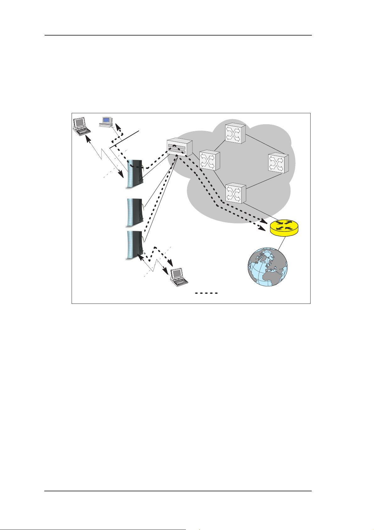
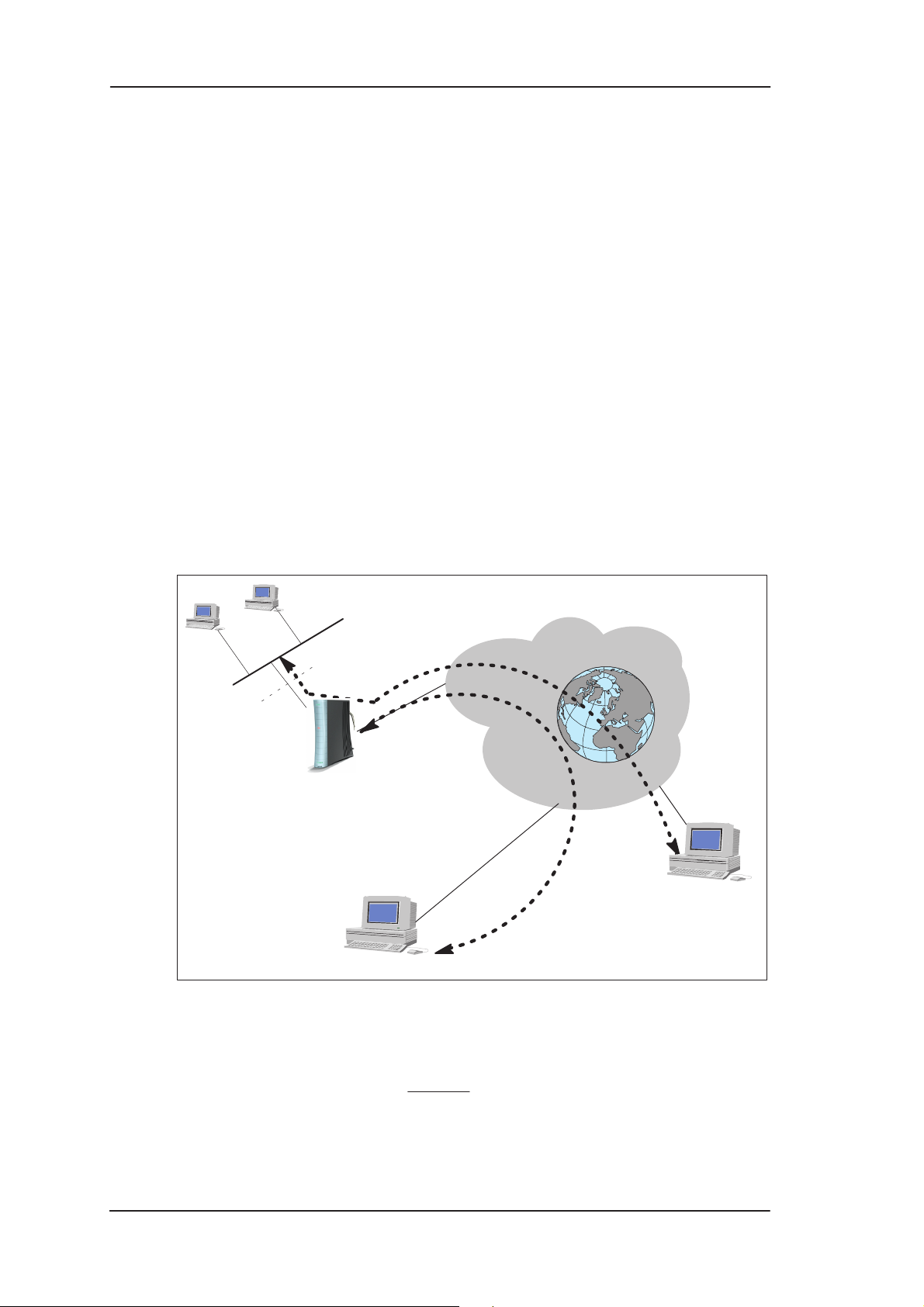
Internet access
Your access to the Internet is provided by your Internet Service
Provider (ISP). Nokia MW1 122 connects you through your telephone
line and the ATM (Asynchronous Transfer Mode) network to the
network of your ISP, which, in turn, is connected to the Internet.
Hence, all your data goes through the ISP’s network. If you are using
only one ISP for your Internet access, your ISP may give you a limited
set of IP addresses belonging to its address space that you may utilise
in your desktop and laptop computers on your home network.
However, in many cases it is more practical to separate your own
private LAN from the ISP’s public network by using private IP
addresses. This way you are not limited to the number of public IP
addresses provided by your ISP but you can manage your own address
space independently. For this you will need to use NAPT (Network
Address Port Translation) feature available in your MW1 122 modem.
C33902001SE_00
E Copyright Nokia Networks Oy
2-1
Page 13
MW1 122 Administrator Manual
This mode of operation reduces the need to have more than one public
Internet address. Furthermore, it prevents others from seeing and
accessing your private network and therefore it acts as a simple
firewall.
Wireless
LAN
Customer
premises
LAN
10Base-T
Wireless
LAN
DSLAM
ATM
network
RAN
Internet
Internet connection
2-2
Figure 2-1 High-speed Internet access
E Copyright Nokia Networks Oy
C33902001SE_00
Page 14
Applications and features
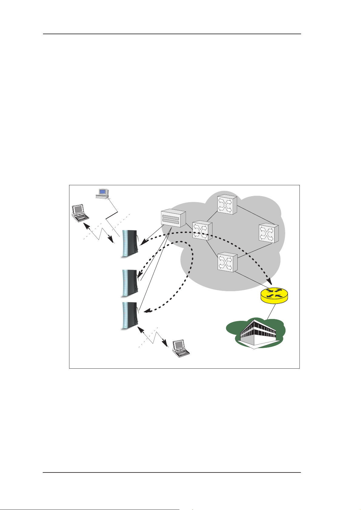
Remote work
Another application for MW1122 is remote work. In this case the
end-to-end architecture can, for example, use PPP over Ethernet,
where a dial-up-type PPP connection is created between your home PC
and your corporate networks PPP access server based on the user name
and password you issue in your PC. The same set up could be used for
accessing the public Internet with a different user name and password.
This example naturally presumes that your ISP supports this type of
approach for providing remote work services for our company.
Remote
worker 1
DSLAM
10Base-T
ATM
network
Wireless
LAN
Nokia MW1122
Remote
worker 2
Remote
worker 3
PPPoE
RAN L2TP
Company
router
Corporate
network
Figure 2-2 Remote work using MW1122 as a standard router
C33902001SE_00
E Copyright Nokia Networks Oy
2-3
Page 15
MW1 122 Administrator Manual
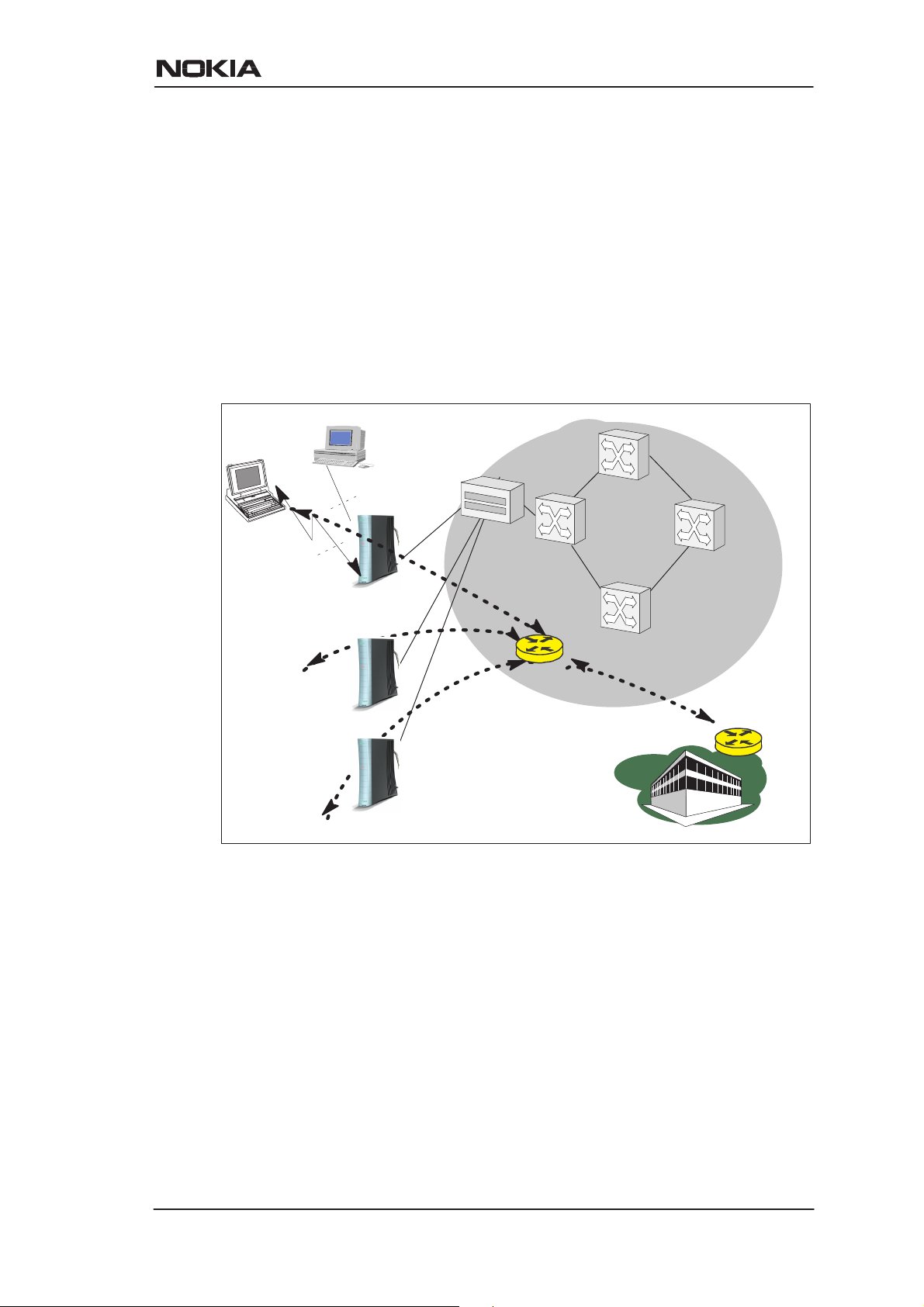
LAN interconnection
MW1122 can also be used for corporate branch office LAN
interconnection. Especially, when the branch office is a small and
possibly a temporary site without any existing LAN infrastructure
available, the MW1122 is highly suitable for this purpose. In such
circumstances the wireless LAN is an excellent technology to have
office coverage fast and without any additional wiring installations.
Local file and printer servers, if needed, may be connected with the
10Base-T Ethernet interface to MW1122 and all client PCs and laptops
may be using wireless LAN to access the servers, the printer, and the
corporate intranet. As a bridge, MW1122 enables all network
protocols to be used on the corporate network.
Wireless
LAN
Remote
office 1
Remote
office 2
Remote
office 3
LAN
10Base-T
wireless
LAN
DSLAM
ATM
network
Company
bridge
Corporate
network
Figure 2-3 LAN interconnection
2.2 Features
MW1122 can operate as a bridge and/or Internet Protocol (IP) router
between Ethernet, wireless LAN and the virtual channels of
ADSL/ATM interfaces supporting both dynamic and static routing.
2-4
E Copyright Nokia Networks Oy
C33902001SE_00
Page 16
2.2.1 Interfaces
MW1122 has the following interfaces:
D Ethernet interface (LAN)
D Wireless LAN interface (WLAN)
D 8 ATM VCC interfaces
D ATM VCC management interface
D Gateway/bridge management interface. This interface is used as a
bridge host interface or gateway interface depending on the
operation mode. In this manual it is called VBRIDGE. On the
MW1122 web pages, the interface is called gateway or bridge IP
interface.
MW1122 can operate in four different main modes:
D Bridging only
D Routing/tunneling IP only
D Routing/tunneling IP, bridging all but IP
D Routing/tunneling IP and bridging all, including IP
Applications and features
The mode in which MW1122 operates depends on the configuration of
the unit’s interfaces. Table 2-1 shows the operational modes and the
corresponding interface configurations.
LAN interface WLAN inter-
face
Bridge only
Bridging Bridging or
slaved to LAN
interface (single
subnet).
Route/tunnel IP only
Routing (IP address configured)
Routing (IP address configured) or slaved
to LAN interface
(single subnet).
ATM VCC interfaces
Bridging. Used as a man-
Routing (IP address configured) or PPTP
local tunneling
activated for
each active
ATM VCC.
Vbridge
(gateway/host
interface)
agement (host)
interface for all
bridged interfaces in case
such is needed.
Not used in this
case. The unit
can be managed through
any of the LAN,
WLAN or ATM
interface IP addresses.
C33902001SE_00
E Copyright Nokia Networks Oy
2-5
Page 17

MW1 122 Administrator Manual
LAN interface Vbridge
Routing (IP address configured) and
bridging activated.
WLAN interface
Route/tunnel IP, bridge all other traffic
Routing (IP address configured) and
bridging activated or slaved
to LAN interface
(single subnet).
ATM VCC interfaces
VCCs that only
route or tunnel
have routing (IP
address configured) or PPTP
local tunneling
activated.
VCCs that both
bridge and
route have additionally bridging
activated. This
requires ETHLLC encapsulation to be used
on those VCCs.
VCCs that only
bridge have
only bridging
activated.
(gateway/host
interface)
Typically not
used in this
case. The unit
can be managed locally
through LAN
and WLAN interfaces and remotely through
a separate
management
VCC or the ATM
VCCs which
have routing
activated.
Route/tunnel IP, bridge all other including IP
Bridging activated
Bridging activated or slaved
to LAN interface
(single subnet).
VCCs that only
route or tunnel
have routing (IP
address configured) or PPTP
local tunneling
activated.
VCCs that only
bridge have
only bridging
activated.
Used as a common IP gateway
interface for
both LAN and
WLAN interfaces.
Table 2-1 Operational modes
LAN and WLAN interfaces
LAN and WLAN interfaces can be configured individually to bridge
and route packets. There are three different operational modes in both
LAN and WLAN interfaces:
2-6
E Copyright Nokia Networks Oy
C33902001SE_00
Page 18

Applications and features
D Bridging only; only bridging is activated in the interface. In this
case the interface bridges all protocols.
D Routing only; only IP address is configured in the interface. In this
case, the interface routes IP packets.
D Bridging and routing; Bridging is activated in the interface and IP
address is configured in the interface. In this case, the interface
routes IP packets and bridges all other packets.
Slaved WLAN operation
The wireless LAN interface can be configured to operate as a slave to
the Ethernet interface. In this case, there is no need to configure the IP
address or bridging to the wireless LAN interface. The Ethernet and
the wireless LAN interface are bridged together internally and both
interfaces are treated as a single LAN interface. All LAN
configuration parameters defining bridging and IP-related parameters,
such as IP address, admin-disabled and RIP configuration address, are
used for both LAN and WLAN interfaces.
Internal host/gateway interface
There is a special host/gateway logical IP interface within MW1122
called VBRIDGE. This interface has a specific purpose in MW1122.
In applications where some A TM virtual channel connections are used
for bridging IP traffic and some other ATM virtual channel
connections are used for routing IP traffic, the VBRIDGE interface
must be used instead of LAN/WLAN IP addresses. Alternatively , this
interface is used in bridge only application when the IP address is
required for remote management purposes.
Data VCC operation
MW1122 supports the following encapsulations in each ATM data
virtual channel individually:
D RFC2684 LLC encapsulation for bridged IP (ETH-LLC)
D RFC2684 LLC encapsulation for routed IP (IP-LLC)
D RFC2364 Virtual circuit multiplexed PPP over AAL5 (PPP-VC)
D RFC2364 Virtual circuit multiplexed PPP over AAL5 used to
tunnel LAN/WLAN/VBRIDGE PPTP packets
(TUNNELED-PPP-VC)
If an IP address is given to a virtual channel interface and bridging is
enabled at that interface, then IP data at that interface is routed and all
other protocols are bridged. The only encapsulation which allows both
bridging and routing simultaneously is ETH-LLC. For example, it is
C33902001SE_00
E Copyright Nokia Networks Oy
2-7
Page 19

MW1 122 Administrator Manual
possible to route ETH-LLC encapsulated packets and at the same time
bridge, for example, PPPoE packets (PPPoE packets are transported
directly over Ethernet frame, not within IP packets).
2.2.2 Routing
Routing is based on routing entries in a routing table. Static routes are
added via the management interface and dynamic routing is done using
RIP and RIPv2. Routing is done between the Ethernet 10Base-T
interface, the wireless LAN interface and the virtual channel
connection (VCC) of the A TM/ADSL interface. MW1122 supports up
to 8 simultaneous VCCs.
MW1122 supports IGMP (Internet Group Management Protocol)
proxy receive function for IP multicast applications.
2.2.3 Bridging
Bridging is supported to provide full protocol transparency. Bridging
can be used simultaneously with IP routing. MW1122 works as a
self-learning bridge supporting up to 1024 MAC addresses. Bridging
is done between the Ethernet 10Base-T interface, the wireless LAN
interface and each ATM VCC interface. Optionally, the bridging
between the VCCs can be disabled.
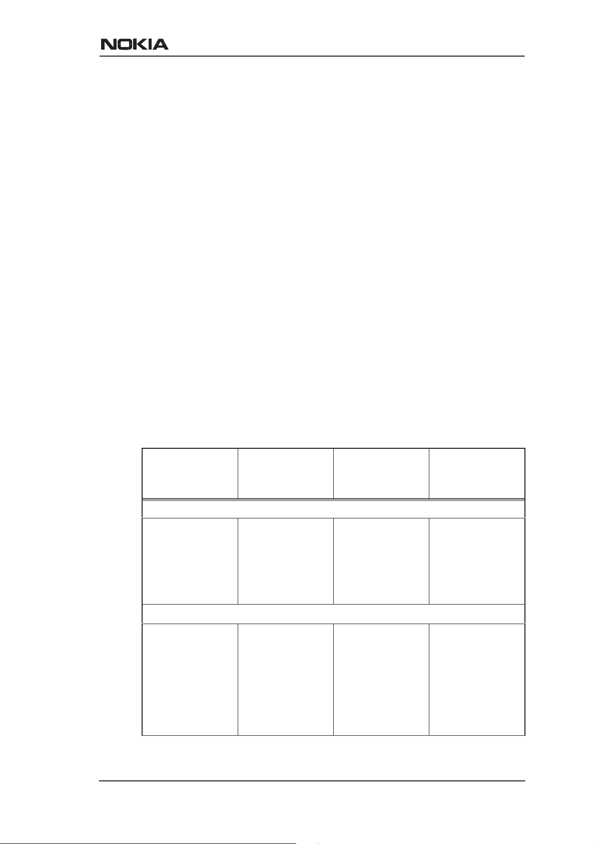
2.2.4 Network Address Port Translation
MW1122 supports Network Address Port Translation (NAPT) for
TCP/IP , UDP/IP and ICMP/IP protocols. When NAPT is used, a single
IP address is allocated to a VCC which leads to the public IP network.
The Ethernet subnet has private IP addressing and is not visible to the
VCC. NAPT translates the IP source address and source port number
dynamically to the VCC IP address and port number. Similarly,
packets coming from the VCC are mapped back to the original
destination addresses. NAPT allows up to hundreds of hosts to share a
single VCC IP address to the public network. The principle of Network
Address Port Translation is presented in Figure 2-4.
2-8
E Copyright Nokia Networks Oy
C33902001SE_00
Page 20
Applications and features
Home network (LAN) Internet (WAN)
src:192.168.1.112:1228
dst:194.112.11.111:80
src:194.112.11.111:80
dst:192.168.1.112:1228
NAPT router
192.168.1.254
src:195.112.12.161:50001
dst:194.112.11.111:80
src:194.112.11.111:80
dst:195.112.12.161:50001
195.112.12.161
Figure 2-4 Principle of Network Address Port Translation
NAPT may restrict the operation of some IP applications. NAPT also
operates as a simple IP firewall because translation is only allowed
when the first packet is transmitted from the LAN. This means that the
NAPT table entry is created only when a packet is sent from the home
network to the Internet. With server support capability, the user can
add static entries to the NAPT table allowing the translation always in
both directions. This capability is used to add servers (HTTP, NNTP,
and FTP), which are visible to the public IP network via the VCC, on
the LAN subnet.
NAPT supports most IP-based protocols. Because NAPT operates on
the IP and transport layer , the application that includes IP address and
port within the payload will not work properly through NAPT . In many
cases, these applications can be passed through the NAPT using
Application Layer Gateway functionality (ALG). MW1 122 has ALG
for the following protocols/applications:
D ICMP
D FTP
D H.323 including NetMeeting
D CUSeeMe
D PPTP
D IRC
D IPSEC ESP tunnel mode and IKE
Note, that most IPSEC implementations will fail when passed through
NAPT. A typical reason is that the identification may fail if the
identification is based on IP address. Also, only tunnel mode without
Authentication Header (AH) works.
C33902001SE_00
E Copyright Nokia Networks Oy
2-9
Page 21

MW1 122 Administrator Manual
2.2.5 Dynamic Host Configuration Protocol
MW1122 can act as a Dynamic Host Configuration Protocol (DHCP)
server for the PCs on the end-user home network. In this mode,
MW1122 can assign up to 253+253 consecutive addresses from two
separate address ranges (that is, 253 consecutive addresses per address
range) to the PCs on the home network. Two separate address ranges
are used when LAN and WLAN are operating as separate subnets.
MW1122 can also act as a DHCP relay agent and relay the DHCP
requests to an external DHCP server.
2.2.6 ATM and ADSL
MW1122 supports up to 8 simultaneous VCCs and supports UBR
(Unspecified bit rate) traffic shaping on all VCCs. The maximum
transmit rate on each VCC is the ADSL upstream capacity. If more
than one VCC is transmitting simultaneously, the ADSL upstream
capacity is temporarily shared between these VCCs. When one VCC is
idle, the bandwidth is used by another VCC.
The ADSL transmission is based on the DMT line code. MW1122
provides a DMT line rate up to 8 Mbit/s downstream and up to 800
kbit/s upstream. The DMT transceiver is rate adaptive and capable of
providing faster rates over short distances or slower rates over long
distances. The transceiver adapts itself to the line conditions.
MW1122 supports also ADSL Lite. In the ADSL Lite mode, the
maximum line rates are 1536 kbit/s downstream and 512 kbit/s
upstream.
MW1122 supports both G.992.1 and G.992.2 ADSL
recommendations defined by ITU-T.
Rate adaptation is done in steps of 32 kbit/s. The ADSL interface of
MW1122 functions completely automatically and all configuration
related to the ADSL connection is done at the access multiplexer in the
operator’s premises. The network operator can set the data rates as a
part of the network management functionality provided by Nokia
DSLAM.
2.2.7 Point-to-Point Tunneling Protocol (PPTP)
2-10
When PPTP local tunneling is used, a local network client initialises a
PPTP-tunneled PPP connection (VPN) to Nokia MW1122. The
modem terminates the tunnel and all data from that terminated local
PPTP tunnel will be forwarded to an assigned A TM VCC by using PPP
E Copyright Nokia Networks Oy
C33902001SE_00
Page 22
Applications and features
over AAL5 encapsulation. Thus, each local PPTP tunnel requires an
equivalent ATM VCC assigned to it restricting the total number of
local PPTP hosts to 8.
Local tunneling is used when there is a need to have one or more
computers connected independently to different networks. For
example, in remote work application, the rest of the family may be
using the common ISP services and one or two family members need to
gain access to their corporate networks. With local tunneling, these
remote workers may be connected to a different network than the rest
of the users.
Local tunneling is activated using the PPTP client running, for
example, in Windows The destination IP address must be MW1122
LAN/WLAN/VBRIDGE IP address depending on the configuration.
PPP packets within PPTP are mapped to the configured VCC.
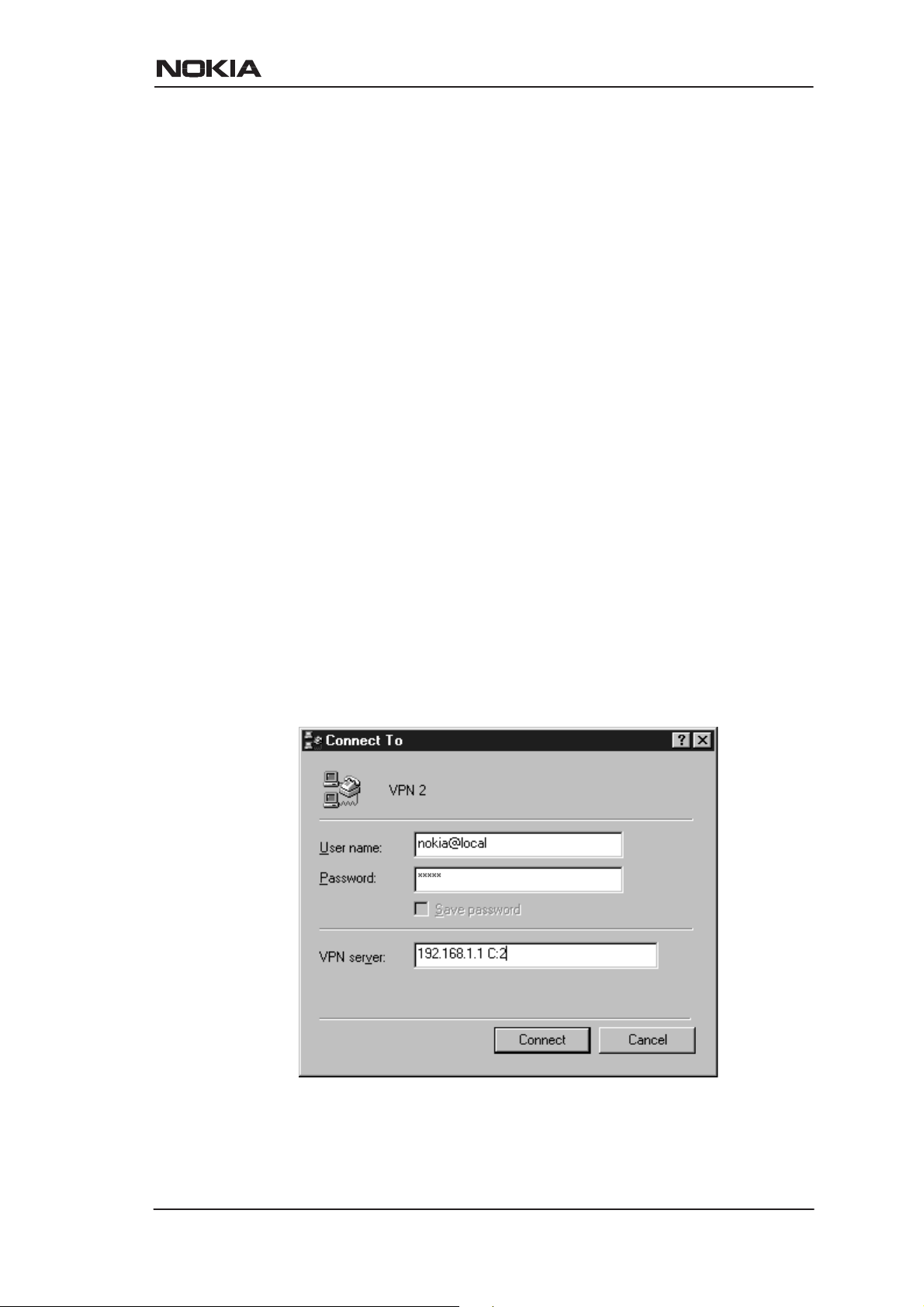
MW1122 has three dif ferent ways to choose the A TM VCC that will be
used for tunneling:
D Automatic, chooses the first free VCC
D Chooses the VCC number using C:number, where number is from
1 to 8. C:number is typed after the MW1122 IP address in PC’s
PPTP client Connect To window (see Figure 2-5).
D Chooses the VCC number using N:name, where name is the
VCCx description. N:name is fed after the MW1122 IP address.
Figure 2-5 Choosing the VCC2 for tunneling example
C33902001SE_00
E Copyright Nokia Networks Oy
2-11
Page 23

MW1 122 Administrator Manual
2.2.8 Point-to-Point Protocol over Ethernet (PPPoE)
Standard PPPoE mode is used when MW1 122 is operating as a bridge.
PPPoE protocol defines how PPP sessions are mapped into Ethernet
packets. When MW1122 operates as a bridge, this protocol is
transparent to MW1122.
2.2.9 Payload encapsulations
Both routed and bridged protocols are encapsulated in the A TM link by
using either RFC 2684 LLC/SNAP encapsulation or VC multiplexing.
MW1122 also supports PPP over AAL5 encapsulation, in which
routed protocols are first encapsulated in PPP (RFC 1661). PPP is then
encapsulated in ATM according to the IETF PPP over AAL5 using
RFC 2364 VC multiplexing or LLC/NLPID encapsulation.
2.2.10 Access list authorisation
When a wireless LAN is used, it is important to be able to control the
clients accessing to MW1122. Therefore, MAC-address-based access
control may be used. It prevents all communications to a such client
whose MAC address does not appear on the access list. When a new
client is brought to the network, its MAC address needs to be added to
the access list. This can be done manually through the local command
line interface (CLI) or with a Web browser management.
2.2.11 Wireless LAN and radio interface
MW1122 supports wireless LAN to be used as one of the interfaces.
The wireless LAN utilises Nokia C110/C111 Wireless LAN PC card
which needs to be inserted to the designated PC Card slot on the back
panel of the modem. Only Nokia C110 or C111 Wireless LAN cards
can be used. Without a wireless LAN card, MW1122 operates as a
normal ADSL terminal with one 10Base-T Ethernet interface. The
wireless LAN card can be inserted to the PC Card slot while the
modem is operating and the wireless LAN connectivity will be
achieved without restarting the modem. Only the WLAN subsytem
must be reseted through the web interface or the command line
interface.
2-12
Wireless LAN used in MW1122 is based on IEEE802.11 standard
operating at 2.4 GHz radio band. The band has been divided into
subchannels which are dependent on local regulations. Typically, in
Europe, there are 13 and, in USA, 11 channels. The transmission
E Copyright Nokia Networks Oy
C33902001SE_00
Page 24

Applications and features
power is limited to 100 mW/MHz giving typical indoor coverage of 20
to 50 metres.
2.2.12 Wired Encryption Privacy (WEP)
MW1122 supports full-speed WEP encryption and both
authentication methods defined in IEEE 802.11b: Open-key and
shared-key authentication. The encryption is 40-bit RC4 WEP
encryption. Additionally, MW1122 supports 128-bit RC4 WEP
encryption.
2.2.13 Weighted Fair Queueing (Class of Service)
As a Class of Service (CoS) function, MW1122 supports Weighted
Fair Queueing (WFQ) for each ATM VCC. The CoS function ensures
that different IP traffic flows are treated fairly in the upstream (towards
the Internet) direction. This may be necessary, in some cases, because
the upstream capacity of the ADSL line is somewhat limited compared
to the Ethernet bandwidth on the office or home LAN. The WFQ CoS
function classifies IP traffic flows based on IP address, protocol and
port fields. It is capable of identifying the IP flow from all supported
payload encapsulation formats. WFQ works properly only with
IP-based protocols. If the flow is IP-based but is encrypted using IPSec
or PPP encryption, then WFQ cannot identify the flows correctly. In
this case, the default flow is used and the default flow is treated as a
single flow.
2.2.14 Management
There are three management methods in MW1122:
D Command line interface (CLI) through console serial port
D CLI via telnet
D Web browser management
The CLI allows complete configuration of the unit; the Web browser
management allows the configuration of the most frequently used
configuration parameters.
2.2.15 Dedicated management channel
The operator or the Internet Service Provider can establish a dedicated
management channel to MW1122. This channel provides access to the
C33902001SE_00
E Copyright Nokia Networks Oy
2-13
Page 25
MW1 122 Administrator Manual
MW1122 management (with telnet or W eb browser) and it can be used
to upload a new software to MW1122.
The dedicated management channel is separated from the other IP
stack. It is not possible to access the other interfaces or networks
behind the data interfaces through the dedicated management channel.
Similarly , access from LAN/WLAN or data VCCs to the management
channel is blocked. The management channel supports only routing
using the following encapsulations:
D RFC2684 LLC encapsulation for bridged IP (ETH-LLC)
D RFC2684 LLC encapsulation for routed IP (IP-LLC)
D RFC2364 Virtual circuit multiplexed PPP over AAL5 (PPP-VC)
In Figure, 2-6 VCC1 is used for customers data transmission.
Administration through this channel has been disabled. The operator
or the service provider uses the management VCC for management
purposes only.
LAN
10Base-T
Home
network
Nokia
MW1122
ISP’s NMS Network management system
VCC1/Data
(admin disabled)
Management VCC
Figure 2-6 Dedicated management channel
Internet
2-14
E Copyright Nokia Networks Oy
C33902001SE_00
Page 26
Interfaces and indicator lights
Chapter 3
Interfaces and indicator lights
This chapter describes the external interfaces of MW1122 and
introduces its front panel indicator lights.
3.1 Interfaces
MW1122 has one ADSL line interface and two LAN interfaces
WLAN and 10Base-T Ethernet. It also has a local management
interface (CLI) for management purposes. The ADSL line interface is
compatible with ITU-T G.992.1 specification. The wireless LAN port
interface supports Nokia’s 1 1 Mbit/s IEEE 802.1 1b WLAN PC Card.
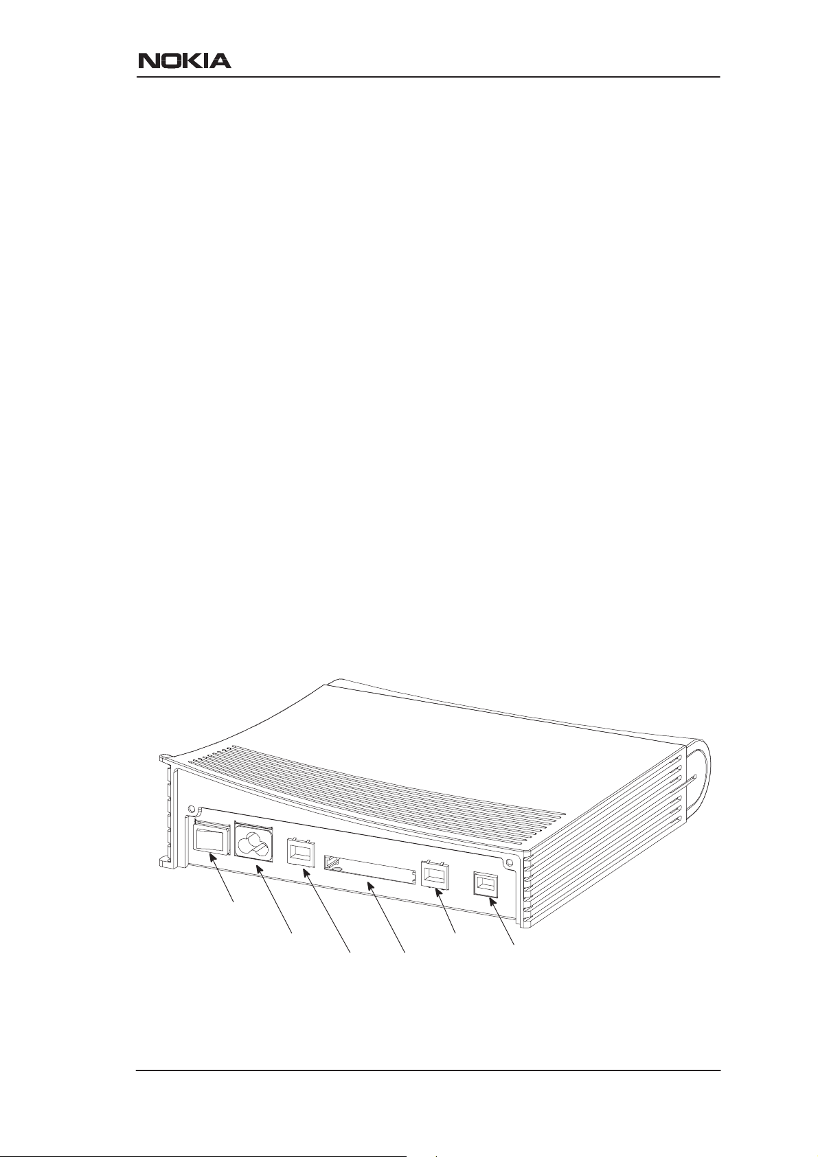
Power switch
Mains connector
Figure 3-1 MW1122 back panel
C33902001SE_00
Ethernet
WLAN (PC card)Local management interface
E Copyright Nokia Networks Oy
ADSL line
3-1
Page 27
MW1 122 Administrator Manual
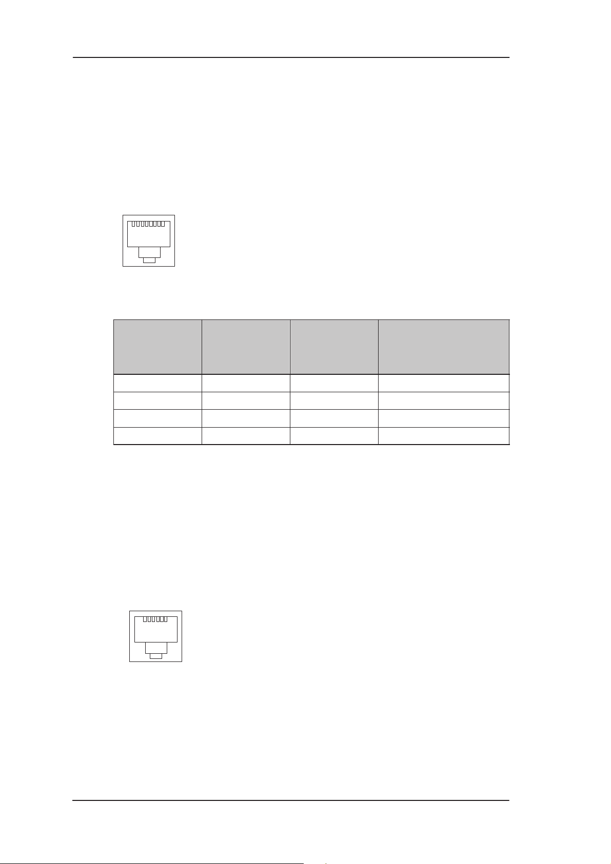
3.1.1 Ethernet interface
The Ethernet interface (ETH) is located on the back panel. The
Ethernet interface is a standard 10 Mbit/s half-duplex 10Base-T
interface. The mechanical connector is an 8-pin RJ-45. The pin-out
numbering is shown in Table 3-1.
18
Figure 3-2 ETH connector
PIN Signal Direction
1 Tx+ –> Transmit data +
2 Tx– –> Transmit data –
3 Rx+ <– Receive data +
6 Rx– <– Receive data –
Table 3-1 Ethernet interface pin-out numbering
3.1.2 ADSL interface
The ADSL interface (DSL) is compatible with ITU-T G.992.1
specification. The mechanical connector is a 6-pin RJ-11. The pin-out
numbering is shown in Table 3-2.
16
MDI signal
MW1122-
Ethernet
3-2
Figure 3-3 DSL connector
E Copyright Nokia Networks Oy
C33902001SE_00
Page 28
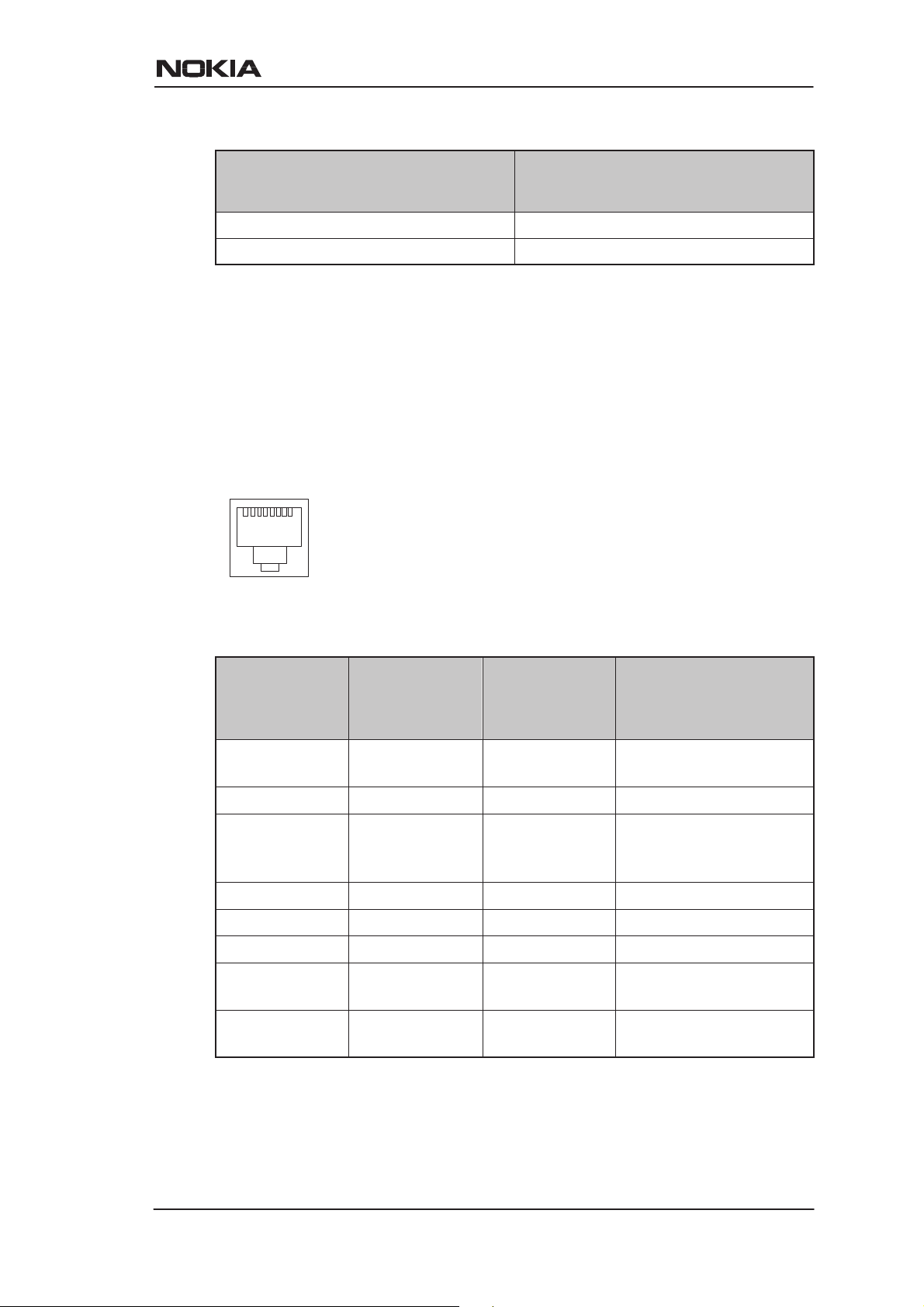
PIN Signal
3 DSL1
4 DSL2
Table 3-2 ADSL interface pin-out numbering
3.2 Command line interface
The command line interface (CLI) is RS-232 interface with an RJ-45
mechanical connector . The pin-out numbering is shown in Table 3-3.
18
Interfaces and indicator lights
Figure 3-4 CLI connector
PIN Signal Direction
1 107 DSR
(const. ON)
2 108 DTR <– Data terminal ready
3 109 DCD
(const. ON)
4 102 SG Signal ground
5 103 TxD <– Transmitted data
6 104 RxD –> Received data
7 105 RTS
(not in use)
8 106 CTS
(const. ON)
MDI signal
M5112-ter-
minal
–> Data set ready
–> Data channel re-
ceived line signal detector
<– Request to send
–> Clear to send
Table 3-3 Command line interface pin-out numbering
C33902001SE_00
E Copyright Nokia Networks Oy
3-3
Page 29
MW1 122 Administrator Manual
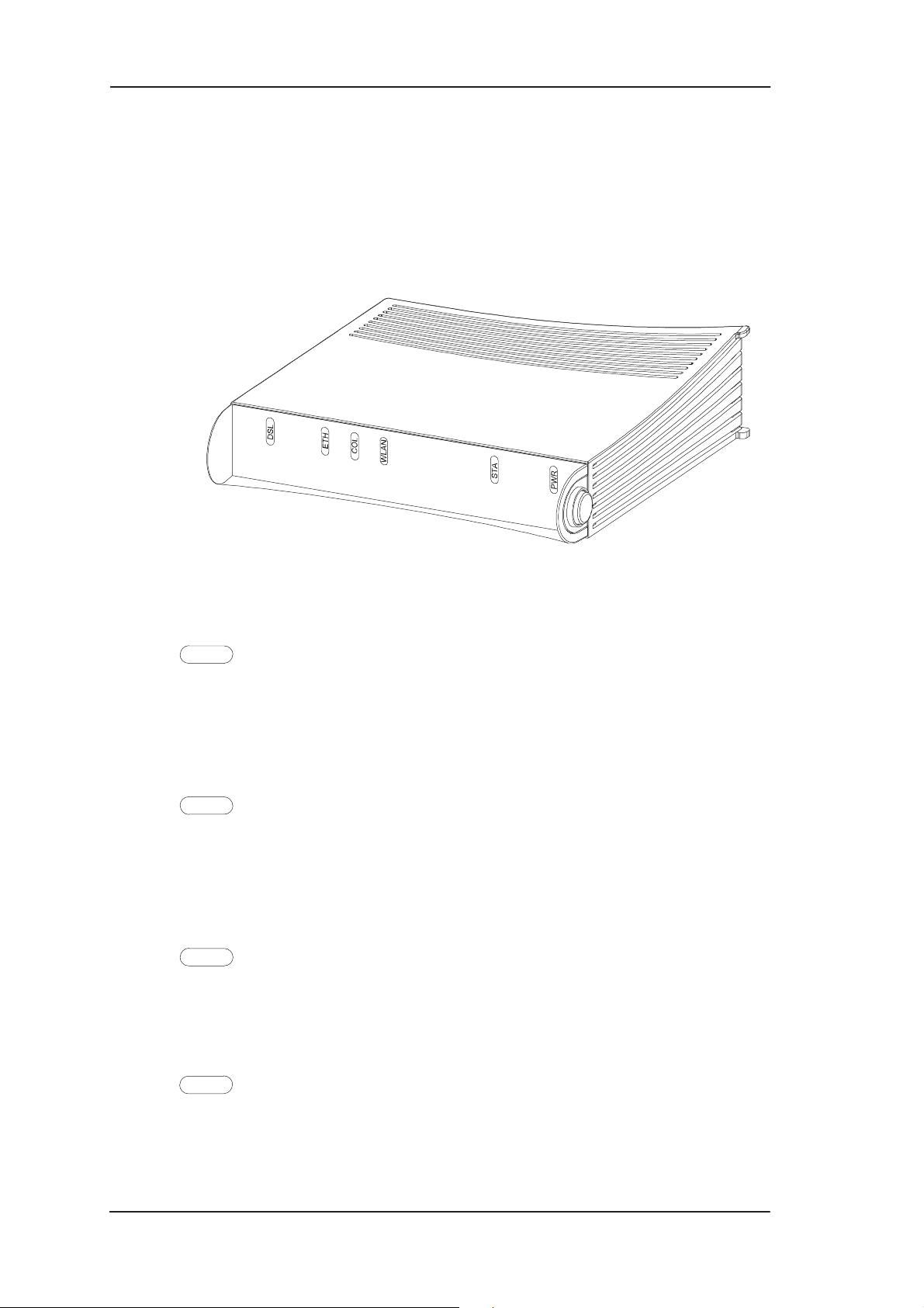
3.3 Indicator lights
MW1122 has six indicator lights on the front panel: PWR, STA,
WLAN, COL, ETH, and DSL. STA indicator is red. Other indicators
are green.
Figure 3-5 MW1122 front panel indicators
DSL
GREEN
Off ADSL link is down.
Blinks ADSL connection is being established.
On ADSL link is up.
ETH
GREEN
Off Ethernet is down.
On 10Base-T Ethernet is functional
Blinks Receives traffic from Ethernet.
COL
GREEN
Blinks Collisions on the Ethernet. Note, that it is normal that some
collisions occur on the Ethernet.
3-4
WLAN
GREEN
Off No stations on the WLAN or WLAN PC Card not
inserted.
E Copyright Nokia Networks Oy
C33902001SE_00
Page 30

Interfaces and indicator lights
On Stations on the WLAN but no traffic.
Blinks Receives traffic through the WLAN interface.
STA
RED
Off OK
On Hardware malfunction during startup.
PWR
GREEN
Off Power off.
On Power on.
C33902001SE_00
E Copyright Nokia Networks Oy
3-5
Page 31

MW1 122 Administrator Manual
3-6
E Copyright Nokia Networks Oy
C33902001SE_00
Page 32

Chapter 4
Installing Nokia MW1122
Installing Nokia MW1122
This chapter presents a step-by-step installation procedure of
MW1122. Before starting the installation check that MW1122 is
physically undamaged. The package contains the following items:
D MW1122 modem
D Wireless LAN card and antenna
D ADSL line cable
D 10Base-T Ethernet cable
D power cord
D serial adapter
D User Manual
4.1 MW1122 default settings
Typically, MW1122 has a customer-specific configuration. The
default configuration of a general version is shown in Table 4-1.
C33902001SE_00
E Copyright Nokia Networks Oy
4-1
Page 33

MW1 122 Administrator Manual
Config mode level Parameter Setting
system hostname MW1122
eth IP address 192.168.1.1
wlan regulatory-domain europe
channel varies
network name MW-wxyz, where
255.255.255.0
wxyz are the last four
numbers of the serial
number which can be
found on a sticker in
on the bottom of
MW1122.
slave-to-eth on
vcc1 pvc 0 (vpi) 100 (vci)
ppp-vc (encaps)
IP address 0.0.0.0 0.0.0.0,
means that MW1122
gets its IP address
dynamically from the
network.
IP NAPT on
ppp authentication both-chap-pap
ppp username none
ppp password none
common ip route 0.0.0.0 0.0.0.0 0.0.0.0
vcc1
DHCP mode server
Table 4-1 MW1122 default settings
4.2 Step-by-step installation procedure
1. Plug the mains power cord to a mains outlet.
2. Plug the antenna into the antenna connector of the wireless LAN
card, if needed.
4-2
E Copyright Nokia Networks Oy
C33902001SE_00
Page 34

Installing Nokia MW1122
3. Insert the wireless LAN card gently into the MW1122 wireless
LAN slot on the MW1122 back panel. Ensure that the card is
aligned correctly.
4. Switch on MW1122. The PWR indicator lights up.
5. Ensure that wireless LAN clients have the same configuration as
the wireless LAN card in the MW1122 modem and that they are in
the Infrastructure mode. The default wireless LAN configuration
of MW1122 is the following:
regulatory-domain according to your location of use (Europe,
Canada, USA, or Japan)
network name MW -wxyz (case-sensitive), where wxyz are
the last four numbers from your MW1122
serial number
6. Connect the 8-pin Ethernet cable between your PC and the
Ethernet connector on the MW1122 back panel. Switch on your
PC. The ETH indicator is lit.
7. Connect the 6-pin ADSL line cable between the ADSL connector
on the MW1122 back panel and your ADSL line wall socket. If
you want to use telephone and data services simultaneously
connect a splitter according to Figure 4-1. After a while, the DSL
indicator starts blinking indicating that the ADSL connection is
being established. After the connection has been established
successfully the DSL indicator remains lit.
C33902001SE_00
E Copyright Nokia Networks Oy
4-3
Page 35

MW1 122 Administrator Manual
splitter
Figure 4-1 MW1122 and splitter connected
Now, your MW1122 has been connected and you can check the
connections according to your service provider’s instructions. See
Chapter 5 Managing MW1122 for instructions on how to configure
MW1122.
4-4
E Copyright Nokia Networks Oy
C33902001SE_00
Page 36

Chapter 5
Managing MW1122
Managing MW1122
This chapter shows some operational examples of MW1122. The
examples can be used as a guide when you are planning your
configuration. After the operational examples, we introduce the
management methods of MW1122. First we show how to use the web
browser management and then the command line interface (CLI) will
be presented. The command line interface section contains all CLI
commands.
5.1 Operational examples
This section presents some typical operational examples and the
corresponding configurations. Figure 5-1 shows a general block
diagram of the IP forwarding and bridging functions of MW1 122.
C33902001SE_00
E Copyright Nokia Networks Oy
5-1
Page 37

MW1 122 Administrator Manual
IP-HOST or IP-FORWARD-STACK
LAN
Bridging between interfaces connected to Bridge group. VBRIDGE
interface is the common IP interface for all bridge only interfaces
(Routing or NAPT routing or tunneling)
WLAN
VBRIDGE
VCC1
VCC2
VCC3
VCC4
Bridge group
VCC5
VCC6
VCC7
VCC8
MNGTVCC
IP
Bridge/
IP
Bridge/
IP
Bridge/
IP
WLAN
Mini-
Bridge
group
Bridge/
IP
Bridge/IPBridge/
IP
Bridge/IPBridge/IPBridge/IPBridge/
LAN WLAN VCC1 VCC8VCC7VCC6VCC5VCC4VCC3VCC2 MNGT
Figure 5-1 Block diagram
5.1.1 Routing/tunneling IP only
If the application requires only routing of IP packets, an IP address
should be configured for each interface in use. The example below
shows a typical configuration in such a case.
5-2
MW1122> show conf running
eth
ip address 192.168.1.1 255.255.255.0
wlan
network-name nokia
radio-channel europe 13
ip address 192.168.2.1 255.255.255.0
vcc1
pvc 0 101 ip-llc
ip address 10.98.16.1 255.255.255.0
MW1122>
E Copyright Nokia Networks Oy
C33902001SE_00
Page 38

Managing MW1122
5.1.2 Routing/tunneling IP, bridging other protocols
When the application requires routing IP packets and bridging all other
protocols, then IP address has to be configured and bridging enabled
for all relevant interfaces. The result is that IP packets will be routed
and all other packets will be bridged. In the configuration example
below , LAN and WLAN interfaces route IP traffic and bridge all other
protocols. ATM VCC1 routes IP traffic and ATM VCC2 interfaces
bridges all traffic.
MW1122> show config running
eth
ip address 192.168.1.1 255.255.255.0
bridging
wlan
network-name nokia
radio-channel europe 13
ip address 192.168.2.1 255.255.255.0
bridging
vcc1
pvc 0 101 ip-llc
ip address 10.98.16.1 255.255.255.0
vcc2
pvc 0 102 eth-llc
bridging
MW1122>
5.1.3 Routing/tunneling IP , bridging all protocols including IP
When IP packets that are received from LAN/WLAN must be
routed/tunneled to some ATM VCC and bridged to some other ATM
VCC, then the VBRIDGE interface must be used as this common IP
interface for all bridged interfaces. LAN and WLAN interfaces are in
this case configures as bridge only.
MW1122> show config running
eth
bridging
wlan
network-name nokia
radio-channel europe 13
bridging
vcc1
pvc 0 101 ip-llc
C33902001SE_00
E Copyright Nokia Networks Oy
5-3
Page 39

MW1 122 Administrator Manual
ip address 10.98.16.1 255.255.255.0
vcc2
pvc 0 102 tunneled-ppp-vc
vcc3
pvc 0 103 eth-llc
bridging
vbridge
ip address 192.168.1.1 255.255.255.0
MW1122>
5.1.4 Bridging only
When only bridging is required, all ATM VCCs are configured as
bridge. VBRIDGE IP address can be used as an optional management
interface.
MW1122> show config running
eth
bridging
wlan
network-name nokia
radio-channel europe 13
bridging
vcc1
pvc 0 101 eth-llc
bridging
vcc2
pvc 0 102 eth-llc
bridging
vbridge
ip address 192.168.1.1 255.255.255.0
MW1122>
5.1.5 Routing/tunneling IP only using slaved WLAN
In all of the above examples slaved WLAN interface can be used
instead of a dedicated configuration. When WLAN is slaved to LAN
interface, all traffic will be bridged between the LAN and WLAN
interfaces and treated like the traffic is received from LAN interface
only. Similarly , all traffic from ADSL/ATM channels will be directed
to the logical LAN interface where it will be internally bridged and
directed to the physical LAN and/or WLAN interface.
5-4
E Copyright Nokia Networks Oy
C33902001SE_00
Page 40

MW1122> show config running
eth
ip address 192.168.1.1 255.255.255.0
wlan
network-name nokia
radio-channel europe 13
slave-to–eth
vcc1
pvc 0 100 ip-llc
ip address 10.98.16.1 255.255.255.0
MW1122>
5.2 Typical configuration tasks
Managing MW1122
This section provides some typical configuration tasks. These
configuration examples can be done through the command line
interface.
Note
After you have made changes to the configuration, you must save the
configuration if you want it to be active also after restarting MW1 122.
5.2.1 Configuring DHCP and DNS
The DHCP server can be enabled towards LAN, WLAN, and
VBRIDGE ports. When the DHCP server is enabled, up to two address
ranges (scopes) will be automatically generated and bound to
LAN/WLAN/VBRIDGE interfaces, in this order if the interface has an
IP address. Two address ranges will be required when LAN and
WLAN interfaces separate IP addresses resulting that two different
address spaces will be used, one for each interface.
The address range defines pool of IP addresses and parameters like
default gateway, DNS addresses and domain name. The generated
default address range allows up to 253 IP addresses (C class).
Automatically generated address ranges use LAN/WLAN/VBRIDGE
IP address as gateway and DNS server addresses. If one address range
is defined, then automatic binding will be disabled. If optional address
range parameters like gateway or DNS addresses are not defined,
LAN/WLAN/VBRIDGE IP addresses are used as in automatic
binding.
C33902001SE_00
E Copyright Nokia Networks Oy
5-5
Page 41

MW1 122 Administrator Manual
T ypically , when DHCP is used, the advertised DSN addresses point to
LAN/WLAN/VBRIDGE interfaces. In such cases, the DNS proxy
forwards the DNS request to statically configured DNS servers or to
DNS servers learned dynamically vie PPP/IPCP.
The following commands are used to configure DHCP and DNS
settings:
MW1122(conf-common)#dhcp?
usage: dhcp mode
dhcp address
dhcp gateway
dhcp dns
dhcp lease-time
dhcp domain-name
MW1122(conf-common)#dhcp mode server ; this enables
DHCP server
Normally, there is no need to configure the DNS addresses. If the
service provider does not support automatic DNS address allocation,
the DNS servers can be configured as shown by the following
example:
MW1122(conf-common)# dns address primary 1.2.3.4
MW1122(conf-common)# dns address secondary 1.2.3.5
MW1122(conf-common)#
5.2.2 Configuring static and dynamic routing
Routing entries in the routing table are needed in order to forward the
IP packets to the correct interface. MW1122 has both static and
dynamic routes. Static routes are configured manually and dynamic
routes are learned automatically using RIP v1 and RIP v2 protocols.
The following examples show how to configure static routes to
MW1122.
Default gateway for an interface that learns the next hop automatically:
MW1122(conf-common)# ip route 0.0.0.0 0.0.0.0 0.0.0.0
vcc1
5-6
Default gateway for an interface that requires static next hop:
MW1122(conf-common)# ip route 0.0.0.0 0.0.0.0 1.2.3.1
vcc1
E Copyright Nokia Networks Oy
C33902001SE_00
Page 42

Static route for an interface that learns the next hop automatically:
MW1122(conf-common)# ip route 131.132.133.0
255.255.255.0 0.0.0.0 vcc1
Static route for an interface that requires a static next hop:
MW1122(conf-common)# ip route 131.132.133.0
255.255.255.0 1.3.5.1 vcc1
MW1122 can have only one default gateway. The interfaces that can
learn gateway/peer address dynamically can use value 0.0.0.0 instead
of the next hop address.
5.2.3 Encrypting wireless connection
The minimal WEP encryption configuration is very simple. WEP
mode has to be selected, at least one key has to be configured and the
key has to be selected. In MW1122, the possible keys are numbered
from 1 to 4. In some WLAN products the numbering may be from 0 to
3. In those cases, key 0 equals key 1 in MW1122. Four keys are
available to enable easy change of keys when the keys are changed at
different times for different clients. A simple WEP configuration is
shown in the following example:
MW1122(conf-wlan)# wep mode required
MW1122(conf-wlan)# wep key-entry 1 40-bit 0987654321
MW1122(conf-wlan)# wep default-key 1
MW1122(conf-wlan)#
Managing MW1122
If you want to use 128-bit keys, you must enter a key of 32 characters:
MW1122(conf-wlan)# wep key-entry 1 128-bit
1234567890abcdef1234567890abcdef
MW1122(conf-wlan)#
The MAC Client table and station-specific keys are configured in the
following example:
MW1122(conf-wlan)# sta pc_1 00:11:22:33:44:55
MW1122(conf-wlan)# sta pc_2 00:11:22:33:44:55 40-bit
1234567890
MW1122(conf-wlan)# sta pc_3 00:11:22:33:44:55 128-bit
1234567890abcdef1234567890abcdef
The first line is the Client table entry only . The second and third lines
configure the WEP key also.
C33902001SE_00
E Copyright Nokia Networks Oy
5-7
Page 43

MW1 122 Administrator Manual
5.2.4 Changing WLAN settings through the command line interface
Y our Nokia MW1122 is defined to have default settings as described in
section 4.1. Sometimes you may have to modify these settings. In this
section you can find instructions on when and how to change these
settings.
Changing WLAN network name
By default, your MW1122 has the WLAN network name MW-wxyz,
where wxyz are four last numbers of the serial number of your
MW1122. You can change this to suit your needs and make your
network uniquely identifiable. T o change the WLAN network name of
MW1122:
1. Open a telnet or CLI session to MW1122 as described earlier in
this chapter .
2. Start the configuration mode by typing
3. Go to wlan configuration level by typing wlan ENTER.
4. Give new network name by typing
new_network_name ENTER where new_network_name is your
new network name. Note, that network name is case-sensitive.
5. Remember to change the network names of your WLAN clients,
also.
configure ENTER.
network-name
Changing WLAN channel
Sometimes, if there are other wireless LAN devices or devices using
2.4 GHz frequency nearby, it may be necessary to change the WLAN
channel used by Nokia MW1122. The available channels depend on
the regulatory domain. After selecting a new channel, remember to
reset the WLAN subsystem of your Nokia MW1122 as described
below.
1. Open a telnet or CLI session to MW1122 as described earlier in
this chapter .
2. Check your current channel by typing
show wlan stat
command. The channel is shown on top of the display, on
ap-station line. The ap-station line contains the following
information: MAC address/network name/channel/region.
3. Start the configuration mode by typing configure ENTER.
4. Go to wlan configuration level by typing
wlan ENTER.
5. Set a new channel (5, for example) by typing radio-channel
europe 5 ENTER.
6. Reset wlan subsystem by going to the main mode and giving
reset wlan command.
5-8
E Copyright Nokia Networks Oy
C33902001SE_00
Page 44

Managing MW1122
7. Ensure that the channel has been changed by typing show wlan
stat command.
You have now changed the WLAN channel of your Nokia MW1122
and you can use the wireless LAN normally. You may need to restart
your wireless LAN clients if they do not support automatic channel
scanning. Consult the user manuals of each WLAN client for
instructions on changing their WLAN channels.
Controlling the access to your network
You can control the access to your MW1122 with an access list. By
default, this feature is off in MW1122. This means that all WLAN
clients are allowed to have access to your Nokia MW1122. Therefore it
is important that you identify your WLAN clients, add them on the
access list and activate the admission control function which prohibits
other WLAN clinets from entering your network. This is a major
security issue protecting your wireless network from outsiders. T o add
clients to the access list:
1. Consult your computer’s and WLAN clients’ manuals on how to
find out your WLAN clients’ MAC addresses. For clients running
Windows 95 and 98 operating systems, you can find out the MAC
addresses by running
winipcfg.exe and selecting WLAN card
from the menu. The MAC address is shown in the Adapter
address field.
2. Open a telnet or CLI session to MW1122 as described earlier in
this chapter .
3. Start the configuration mode by typing
configure ENTER.
4. Go to wlan configuration level by typing wlan ENTER.
5. Add an entry on the access list by giving the following command:
sta–address <entry-name> xx:xx:xx:xx:xx:xx, where
entry–name identifies the access list entry (for example, a PC host
name) and xx:xx:xx:xx:xx:xx is the MAC address of the allowed
wireless client.
6. Repeat the
sta-address command if you want to add more
clients on the access list.
7. If you want to remove WLAN clients from the access list, just type
no sta-address xx:xx:xx:xx:xx:xx, where
xx:xx:xx:xx:xx:xx is the MAC address of the wireless station you
want to remove from the list.
C33902001SE_00
E Copyright Nokia Networks Oy
5-9
Page 45

MW1 122 Administrator Manual
Note
You must activate the admission control to prohibit other WLAN
clients from entering your network.
To activate the access list:
1. Open a telnet or CLI session to MW1122 as described earlier in
this chapter.Start the configuration mode by typing configure
ENTER.
2. Go to wlan configuration level by typing wlan ENTER.
3. Activate the access list by giving the admission-control
sta-address ENTER command. You can deactivate admission
control by typing no admission-control ENTER.
4. Type show on the wlan configuration level to view the activated
access list entries.
5.2.5 File system and downloading new firmware using TFTP
MW1122 has a flash file system. Some files in the file system have
special meanings. These files are:
D image.exe; primary application file.
D image.bak; secondary application file used if image.exe has been
corrupted or is missing. It is then renamed as image.exe
automatically.
D startup.cfg; primary configuration file used during startup.
D dhcp.leases; contains DHCP lease table information.
MW1122 has the following commands that can be used for file
handling:
D copy
D rename
D delete
D dir
If you use image.exe as a destination filename with the copy command
and the image.exe already exists, the existing image.exe will be
automatically renamed as image.bak. This guarantees that the
application file exists if MW1 122 loses power during SW download.
5-10
You can update the operating software of MW1122 by downloading
the new software from a TFTP server. T o download and activate new
MW1122 operating software:
E Copyright Nokia Networks Oy
C33902001SE_00
Page 46

Managing MW1122
1. Use CLI to issue
install tftp:/<ip-address>/Gx1x2200.R00 command,
where <ip-address is the IP address of the TFTP server
containing the new software and
file to be downloaded. The command copy
tftp:/<ip-address>/Gx1x2200.R00 image.exe can be used
alternatively.
2. After you will see transfer status SUCCESSFUL
message, restart MW1122 to activate the new software.
Downloading configuration or application from monitor
Monitor is a small application that is executed before the actual
software image is started. Typically the Monitor automatically loads
the application file image.exe. You can activate the Monitor by
pressing “m” followed by “o” in the very beginning of the system
startup:
Gx1x2200.R00 is the name of the
local MAC=00:40:43:02:36:72; Using M111/850 eth conf
Type ’m’ (fast) followed by ’o’ (in 10 sec) to
activate Monitor
Nokia Networks (C) 1999
Nokia Boot
B-R0.0.0. built on Apr 4 2000 11:27:55
MON>
The following commands are available for file handling in the
Monitor:
D rename
D delete
D dir
MW1122 has two methods of retrieving files:
D TFTP
D XMODEM
You can retrieve files from a TFTP server using the commands in the
following example:
MON>ipa 192.168.1.1
ip=192.168.1.1
ipserver=0.0.0.0
ipgw=0.0.0.0
serverfile=
MON>ips 192.168.1.100
C33902001SE_00
E Copyright Nokia Networks Oy
5-11
Page 47

MW1 122 Administrator Manual
ip=192.168.1.1
ipserver=192.168.1.100
ipgw=0.0.0.0
serverfile=
MON>file startup.cfg
ip=192.168.1.1
ipserver=192.168.1.100
ipgw=0.0.0.0
serverfile=startup.cfg
MON>eget
tftp loader
ip=192.168.1.1
ipserver=192.168.1.100
ipgw=0.0.0.0
serverfile=startup.cfg
loading file...
file size=556
MON>wri startup.cfg
Writing successful
MON>
A file can also be transmitted from an XMODEM1K running in a PC,
for example, as in the following example:
MON>xget
Start Xmodem1k sending...
MON>wri image.exe
Writing successful
MON>
5.3 Browser management
MW1122 can be managed with a web browser or command line
interface (CLI). The web configuration pages of MW1122 can be
accessed through the Ethernet and wireless LAN ports or through the
ADSL/ATM channels of MW1122. In order to access the web
management feature, the IP functionality must be activated and an IP
address must be given to the corresponding interface.
You can use your PC’s web browser software to access the web
configuration pages in MW1122. To access the web pages you must
know the IP address of your MW1122 or, alternatively, the “name” that
your MW1122 recognises.
5-12
E Copyright Nokia Networks Oy
C33902001SE_00
Page 48

Managing MW1122
Note
Before using your web browser for configuration, you must know the
IP address or the name assigned to your MW1122.
There are three ways to find out whether to use a name or an IP
address:
D Your service provider has given you an IP address for MW1122.
D Your MW1122 uses Dynamic Host Configuration Protocol
(DHCP) and Domain Name Server. In this case the name is
MW1122.
D Your MW1122 uses DHCP. In this case run winipcfg.exe
(Windows 95) or ipconfig.exe (W indows NT). The IP address of
MW1122 is the Default Gateway address shown by the ipconfig
program.
5.3.1 Opening a connection
To open a connection to the Nokia MW1122:
1. Start your web browser.
2. Enter the name (’MW1122’) or IP address of your Nokia MW1 122
in the browser’s Open Location field and press Enter. If you use the
IP address, it has to be assigned to a local port or gateway interface
(VBRIDGE).
3. Type in the username/password as requested. If no
username/password is required, just click OK to proceed. The
Nokia MW1122 Main Page appears.
C33902001SE_00
E Copyright Nokia Networks Oy
5-13
Page 49

MW1 122 Administrator Manual
5.3.2 Main Page
Main Page is shown first when you use a web browser to connect to
MW1122. The currently shown page is shown highlighted on the list
on the left. Clicking an item on the list (Wireless LAN, WLAN Clients,
Service Providers, Local Network, Statistics, Restart, and Save
Config) takes you to the corresponding page.
Note
When you make modifications to the configuration, remember to save
the configuration and restart your MW1122 for your changes to take
effect.
5-14
Figure 5-2 Main Page
E Copyright Nokia Networks Oy
C33902001SE_00
Page 50

The Main Page shows you the statuses of the DSL line, Ethernet
interface, and wireless LAN interface. It also shows the number of
wireless LAN clients, wireless LAN network name and the channel in
use. Software and hardware versions and the serial number of
MW1122 are shown in the bottom of the page.
5.3.3 Wireless LAN page
You can change wireless LAN network settings on the Wireless LAN
page.
Managing MW1122
Figure 5-3 Wireless LAN page
Note
When you click the Apply button, the WLAN subsystem will be
reseted automatically . If you have changed the network name and you
are accessing MW1122 through the wireless connection, the
connection will be disconnected. You must reconfigure the network
name of the wireless LAN client to continue configuration. The
Reload button restores the settings if you have not saved the
configuration yet.
Network name identifies your network and must be the same in all
wireless LAN clients on your network.
C33902001SE_00
E Copyright Nokia Networks Oy
5-15
Page 51

MW1 122 Administrator Manual
Set Regulatory domain according to your location of use. The
Regulatory domain setting affects the available Radio channels. The
radio channels corresponding to the regulatory domains are:
Europe 1...13
France 10...13
Canada 1...11
USA 1...11
Japan 14
Change Transmit power if your wireless network becomes weak on the
edges.
5-16
E Copyright Nokia Networks Oy
C33902001SE_00
Page 52

5.3.4 WLAN Clients page
On the WLAN Clients page you can enable access control based on the
MAC addresses of the wireless LAN clients. When access control is
enabled, only the wireless stations on the Client table are allowed
access to your wireless network. On this page, you can also activate
Wired Equivalent Privacy (WEP) and set the encryption key
parameters. Note, that unless you have encryption enabled other
WLAN clients nearby have the possibility of monitoring the traffic on
your wireless network
Managing MW1122
Figure 5-4 WLAN Clients page
Enabling access control
You can add a wireless station to the Client table by typing its MAC
address to the MAC address field and clicking the Add new button. Use
C33902001SE_00
E Copyright Nokia Networks Oy
5-17
Page 53

MW1 122 Administrator Manual
lower case characters only when typing in the MAC address. Y ou must
identify the wireless station by filling the Name field. Activate the
Client table by selecting Client table MAC address from the Admission
method pull-down list and clicking the Apply button. Click Remove
button if you want to remove a client from the Client table.
Encrypting wireless connection
If you want to activate WEP, you have two options:
D Use a fixed default key for all stations. There are four default keys
available and the key is selected by clicking the corresponding
radio button. Typically , there is no need to use any other key than
number 1.
D Use a separate station-specific key. Enter this key in the Client
table Wep key field.
Before you type the encryption key, select the key length from the
pull-down list. A vailable lengths are 40 bits and 128 bits. If you select a
40-bit key, you must enter a key with 10 characters. If you select a
128-bit key, you must enter a key with 32 characters. The key is a
hexadecimal string, so the available characters are 0, 1, 2, 3, 4, 5, 6, 7,
8, 9, 0, a, b, c, d, e, and f.
Note
Remember to configure the same key to your wireless client. If you use
your wireless client for web configuration, you can copy the key from
the Key field and paste it to the wireless LAN client software. Then you
can click the Apply to activate encryption. Note, that if you enable
encryption on either client or MW1 122 only, the wireless link will be
disconnected until you have enabled encryption on both devices.
There are five security modes which can be chosen from Encryption
mode pull-down list:
D No encryption; In this mode, encryption is always disabled. If a
station tries shared-key authentication, a failed authentication will
result.
D Allowed; In this mode, a station may use either open-key or
shared-key authentication. If a station uses open-key
authentication, encryption is disabled. If a station uses shared-key
authentication, encryption is used.
5-18
E Copyright Nokia Networks Oy
C33902001SE_00
Page 54

Managing MW1122
D Required; In this mode, it is mandatory to use shared-key
authentication. If open-key authentication is used, a failed
authentication will result. When a station uses shared-key
authentication, encryption is always used. Default keys are used if
no station-specific key exists. Broadcast and multicast data will be
encrypted using the default key.
D Required, Wifi; In this mode, a station may use either open-key or
shared-key authentication and in both cases encryption is always
used. Default keys are used if no station-specific keys exist.
Broadcast and multicast data will be encrypted using the the
default key.
D Required, specific keys; In this mode, a station must use
shared-key authentication and station-specific key. If the station
uses open-key authentication or station-specific key is not
available, a failed authentication will result. Successful
shared-key authentication results encryption using the
station-specific keys. Broadcast and multicast data will be
encrypted using the default key.
In most cases, it is acceptable to use default keys. Most modes also
allow concurrent use of station-specific and/or user-specific keys at
the same time. Wifi mode provides lower authentication support but it
supports all certified WLAN clients. Wifi mode is recommended if
other than Nokia wireless LAN cards are used.
Figures 5-5 and 5-6 show Wlan Clients page with default key and
station-specific keys used, respectively. In Figure 5-5, the station
“PC1” on the Client table uses the default key 1. Additonally, the
Client table is used as a MAC address -based access control list. In
Figure 5-6, stations “PC1” and “PC2” use the station-specific key
given in the WEP key field on the Client table. The MAC address
-based access list is not needed, but the default key is used to encrypt
the broadcast/multicast traffic.
Note
If you are using a station-specific key, you must also configure the
default key because it is used for broadcast.
C33902001SE_00
E Copyright Nokia Networks Oy
5-19
Page 55

MW1 122 Administrator Manual
Note
When you click the Apply button, the WLAN subsystem will be
reseted. If you have enabled the access list or changed the encryption
mode and you are accessing MW1122 through the wireless
connection, the connection will be lost. You must reconfigure the
wireless LAN client to continue configuration.
5-20
Figure 5-5 WLAN Clients page and default key encryption
E Copyright Nokia Networks Oy
C33902001SE_00
Page 56

Managing MW1122
Figure 5-6 WLAN Clients page and station-specific key
C33902001SE_00
encryption
E Copyright Nokia Networks Oy
5-21
Page 57

MW1 122 Administrator Manual
5.3.5 Service Providers pages
The Service Providers page can be used to set authentication for A TM
VCCs with PPP encapsulation (Figure 5-7). You can set the
Authentication method and the corresponding Username and
Password. You can also view Network connection information in the
bottom of the page. If you are using PPTP encapsulation, you can
change the name of the connection through the Service Providers page
(Figure 5-8). The name can be used in your PPTP client for tunnel
configuration, see section 2.2.7 Point-to-Point T unneling Protocol.
5-22
Figure 5-7 Service Provider page with PPP configuration
E Copyright Nokia Networks Oy
C33902001SE_00
Page 58

Managing MW1122
Figure 5-8 Service Providers page with PPTP configuration
C33902001SE_00
E Copyright Nokia Networks Oy
5-23
Page 59

MW1 122 Administrator Manual
5.3.6 Local Network pages
The Local Network page as four sub pages: Local ports, DHCP, NAPT,
and Routing.
Local ports
On the Local Network Local Ports sub page you can assign IP
addresses to Ethernet and wireless LAN ports. If you set Physical LAN
interfaces as Single subnet, you don’t have to set the IP address and
subnet mask to the WLAN port. Instead, the Ethernet IP address is
used for both LAN ports (WLAN slaved to LAN).
Note
When you click Apply, the IP addresses are changed immediately. If
the IP address of the interface you are using changes the connection
will be lost. You have to reconfigure the IP address of the accessing
host. For example, in Windows programs winipcfg.exe or
ipconfig.exe must be used first to release the old address and then to
renew to request new address.
5-24
Figure 5-9 Local Network Local Ports page
E Copyright Nokia Networks Oy
C33902001SE_00
Page 60

Managing MW1122
DHCP
On the Local Network DHCP subpage you can enable/disable
Dynamic Host Control Protocol and set the Address ranges from
which the addresses are distributed to the DHCP clients on your
network. You can also set the Domain Name Server addresses here.
Start address is the first address in the address range. The Range size
defines how many addresses the range contains. Subnet mask is the
subnet mask of the addresses in the range. Primary and Secondary
DNSs set the domain name servers for the corresponding address
range. Lease time defines how often the DHCP client must renew its
lease. Domain name defines the domain name for the range.
The DHCP server can be enabled towards LAN, WLAN and
VBRIDGE (gateway interface) ports. When the DHCP server is
enabled, up to two scopes (address ranges) are automatically
generated and bound to LAN/WLAN/VBRIDGE interfaces, in this
order if the interface has an IP address. If your LAN and WLAN
interfaces have separate IP addresses you must configure two address
ranges, one for each interface. In Figure 5-10, scope (a) has been bound
to Ethernet interface and scope (b) to WLAN interface. When the
address ranges are not defined, MW1122 uses the default values for all
DHCP parameters. The default values are:
D Start address is the interface IP address
D Subnet mask 255.255.255.0
D Range size of up to 253 addresses starting from the interface IP
address.
D DNS address is the interface IP address
D Lease time is 60 minutes
D Domain name is null string
If at least one address range has been defined, then IP address, DNS,
domain name and lease time, if defined, override the default values.
C33902001SE_00
E Copyright Nokia Networks Oy
5-25
Page 61

MW1 122 Administrator Manual
5-26
Figure 5-10 Local Network DHCP page
E Copyright Nokia Networks Oy
C33902001SE_00
Page 62

Managing MW1122
NAPT
If Network Address Port Translation (NAPT) has been activated,
servers on your local network are not visible outside your network. On
NAPT page, you can configure pinholes through which you can
provide outside access to your web server from the Internet, for
example.
In the example shown in Figure 5-11, a pinhole has been added on the
Server list. This example means that all TCP traffic coming from the
Internet through VCC1 to ports 80...89 will be mapped to the IP
address 192.168.1.15 ports 90...99 on your local network.
Figure 5-11 Local Network NAPT page
C33902001SE_00
E Copyright Nokia Networks Oy
5-27
Page 63

MW1 122 Administrator Manual
Routing page
On the Local Network Routing sub page you can set static routes and
enable/disable dynamic routing protocols (Routing Information
Protocol version 1 and 2).
T o enable dynamic routing to a particular interface select the Routing
protocol version from the pull-down list and click the Apply button.
RIP versions 1 and 2 are supported. Send v1-compat. v2 option enables
the sending of RIPv2 packets using broadcast. Receive v1-compat. v2
option enables the receiving of both RIPv1 and RIPv2 packets.
To add a static route, type in the Destination network IP address, the
Subnet mask of the destination network, and the Gateway and the
Interface through which the destination network can be reached. Then
click the Add new button. There are two static routes in Figure 5-12.
5-28
Figure 5-12 Local Network Routing page
E Copyright Nokia Networks Oy
C33902001SE_00
Page 64

5.3.7 Statistics page
The Statistics page lets you view a selection of MW1 122 statistics. to
view statistics of a particular function, click the corresponding button
and the statistics view is opened on a separate window.
Managing MW1122
Figure 5-13 Statistics page
C33902001SE_00
E Copyright Nokia Networks Oy
5-29
Page 65

MW1 122 Administrator Manual
5.3.8 Restart page
On the Restart page, you can reset subsystems and restart MW1122.
Figure 5-14 Restart page
5-30
E Copyright Nokia Networks Oy
C33902001SE_00
Page 66

5.3.9 Save Config page
When you change the configuration, all configuration changes are
activated immediately without restart/reload. However, the
configuration will not be saved into the nonvolatile memory. If
MW1122 is restarted or powered down without saving the
configuration, the old configuration will be restored. Clicking the Save
configuration button saves the configuration into the nonvolatile
memory and the old configuration cannot be restored through the web
interface.
Managing MW1122
Figure 5-15 Save Config page
5.4 Command line interface (CLI)
MW1122 can be managed locally through a command line interface
(CLI). The local command line interface is accessed through the local
management console on the back panel. The local management
console interface is an asynchronous V.24/V.28 character-based
interface with the following configuration:
C33902001SE_00
E Copyright Nokia Networks Oy
5-31
Page 67

MW1 122 Administrator Manual
Setting Value
Speed 9600
Parity None
Data bits 8
Stop bits 1
Duplex Full
Flow control None
Table 5-1 Local management console configuration
Use the 10Base-T Ethernet cable with the serial adapter to connect you
PC’s serial port to the local management console interface according to
Figure 5-16.
10Base-T
Ethernet cable
serial adapter
Figure 5-16 Local management cabling
The command line interface can also be accessed through the Ethernet
and WLAN port of MW1122 or through the ATM channels of
MW1122 on top of the telnet protocol. In order to use the CLI through
telnet or the A TM channel, the IP function must be switched on and IP
address must be given to the corresponding interface.
MW1122 can also be managed remotely through a separate ATM
virtual channel. This channel is only used for management purposes.
In order to use this management channel, it has to be activated first and
given an IP address configuration. The management traffic to this
interface is not routed to any other interfaces of MW1122.
5-32
E Copyright Nokia Networks Oy
C33902001SE_00
Page 68

Managing MW1122
The command line interface has been divided into two modes: main
and configuration. The main mode lets you monitor the status and
performance of MW1122. The configuration mode lets you change
MW1122 configuration. The CLI is case sensitive. All commands
must be given in lower case characters. Only file names and strings can
contain upper case characters.
In the configuration mode, functions can be activated by typing the
corresponding command, for example
deactivated by simply typing no bridging. In commands which
require typing in parameter values, the default value can be restored by
typing
de long-retry, for example. de in front of the command
means “default”. If you type in a value which is incorrect (for example,
letters instead of numbers), the CLI prompts you to enter the value
correctly and displays help. You can always get help on the command
or display by typing
help or ? at the command prompt.
bridging. The function can be
You can recall you previous commands by pressing the “up-arrow”
key on your keyboard.
The configuration mode has been divided into levels. Y ou can navigate
through the configuration mode by typing the name of the level. By
typing exit you will return to the main mode. top command returns
you to the root level of the configuration mode (MW1122(conf)#).
The configuration mode levels are:
D system
D password
D eth
D wlan
D vcc1, vcc2, vcc3, vcc4, vcc5, vcc6, vcc7, and vcc8
D vbridge
D mngtvcc
D common.
The example below shows how to access the different levels:
MW1122>
MW1122>conf
MW1122(conf)#system
MW1122(conf-system)#password
MW1122(conf-password)#eth
MW1122(conf-eth)#wlan
MW1122(conf-wlan)#vcc1
MW1122(conf-vcc1)#vcc2
C33902001SE_00
E Copyright Nokia Networks Oy
5-33
Page 69

MW1 122 Administrator Manual
MW1122(conf-vcc2)#vcc3
MW1122(conf-vcc3)#vcc4
MW1122(conf-vcc4)#vcc5
MW1122(conf-vcc5)#vcc6
MW1122(conf-vcc6)#vcc7
MW1122(conf-vcc7)#vcc8
MW1122(conf-vcc8)#vbridge
MW1122(conf-vbridge)#mngtvcc
MW1122(conf-mngtvcc)#common
MW1122(conf-common)#top
MW1122(conf)#exit
MW1122>
5.4.1 Main mode commands
Command Show diagnostic log
Description Displays diagnostic log.
Syntax show log
Arguments all
Example
MW1122> show log
00/00:00:04 HI(1) ATM chann/vcc1/admin.stat up
MW1122>
5-34
E Copyright Nokia Networks Oy
C33902001SE_00
Page 70

Managing MW1122
Command Show DSL line status
Description Displays DSL line status
Syntax show dsl [all]
Arguments all
Example
MW1122> show dsl
hardware-type ALCATEL/DMT
hardware-rev 99111601/POTS/CP
firmware-rev 00002508
activity-statusOPER/FULL
near-end far-end
maximum-bitrate5696kbits 448kbits
actual-bitrate4608kbits 416kbits
noise-margin 3.5dB 0.0dB
output-power 12.0dBm 20dBm
attenuation 48.5dB 0.0dB
corr-fast-fec 0 0
corr-intl-fec 47 0
fail-fast-crc 0 0
fail-intl-crc 0 0
fail-fast-hec 0 0
fail-intl-hec 0 658
flaged-alarms NONE NONE
MW1122>
Command Show Ethernet interface status
Description Displays Ethernet interface status
Syntax show eth [all]
Arguments show eth command shows Ethernet interface state
Example
MW1122> show eth
##eth(up) type
stat-tx-payload 10964 672919 0 0
stat-rx-payload 10968 657690 0 0
MW1122>
C33902001SE_00
and status.
all argument shows also interrupts.
IEEE 802.3/DIX
pkt oct dis err
E Copyright Nokia Networks Oy
5-35
Page 71

MW1 122 Administrator Manual
Command Show wireless LAN interface status
Description Displays WLAN interface status.
Syntax show wlan [all | stat | table]
Arguments show wlan command without arguments shows the
state of the wlan interface and the payload statistics.
all argument shows interrupts, state and payload statistics.
stat argument shows detailed statistics.
table argument shows the current stations on the
wireless LAN.
Example
MW1122> show wlan
##wlan (up) type
IEEE 802.11
pkt oct dis err
stat-tx-payload 2218 926997 0 0
stat-rx-payload 2211 927009 12 0
MW1122>
Command Show ATM status
Description Displays ATM status.
Syntax show atm [all]
Arguments show atm command shows active ATM channels and
traffic statistics.
all shows all ATM information.
Example
MW1122> show atm
##vcc1(up) vpi vci type encap
0 35 DATA_PVC ETH-LLC
pkt oct dis err
stat-tx-payload 223641 2568289 0 0
stat-rx-payload 18030 1440816 0 0
MW1122>
5-36
E Copyright Nokia Networks Oy
C33902001SE_00
Page 72

Managing MW1122
Command Show bridge interface status
Description Displays interfaces which have bridging enabled.
Syntax show bridge if
Arguments None
Example
MW1122> show bridge if
VBRI (up) phys-address
00:99:12:16:10:53
ETH (up) phys-address
00:00:00:00:00:00
WLAN (up) phys-address
00:00:00:00:00:00
VCC1 (up) phys-address
00:00:00:00:00:00
MW1122>
Command Show bridging statistics
Description Displays bridging statistics.
Syntax show bridge stat
Arguments None
Example
MW1122> show bridge stat
in-packet 8518 out-packet 8494
discard 24
MW1122>
C33902001SE_00
E Copyright Nokia Networks Oy
5-37
Page 73

MW1 122 Administrator Manual
Command Show bridging table
Description Displays bridging table.
Syntax show bridge table
Arguments None
Example
MW1122> show bridge table
if phys-address age type
VBRI 00:99:12:16:10:53 n/a forever
VCC1 00:60:08:94:da:a7 0 dynamic
WLAN 00:e0:03:04:0c:c9 15 dynamic
ETH 00:60:08:94:af:d7 0 dynamic
WLAN 00:e0:03:04:0c:e4 0 dynamic
nr-of-entries 5
MW1122>
Command Show PPTP information
Description Displays PPTP information
Syntax show pptp
Arguments None
Example
MW1122>show pptp
VCC3 net-address port status host-cid peer-cid
n/a n/a IDLE n/a n/a
description
Office
MW1122>
Command Show Address Resolution Protocol (ARP) table
Description Displays ARP table.
Syntax show ip arp
Arguments None
5-38
Example
MW1122>show ip arp
VBRIDGE net-address phys-address age
10.98.20.140 00:00:0e:7c:15:d4 00.07
MW1122>
E Copyright Nokia Networks Oy
C33902001SE_00
Page 74

Managing MW1122
Command Show IP interfaces
Description Displays IP interfaces.
Syntax show ip if
Arguments None
Example
MW1122> show ip if
VBRIDGE (up)
net-address net-mask mtu phys-address
192.168.172.2 255.255.255.0 1500 00:99:12:16:10:53
as ETHERNET/RIP DISABLED
MW1122>
Command Show IP statistics
Description Displays IP statistics.
Syntax show ip stat
Arguments None
Example
MW1122> show ip stat
forwarding NO FORWARD out-discards 0
default-ttl 255 out-no-routes 0
in-receives 2355 reasm-timeout 5
in-hdr-errors 0 reasm-reqds 0
in-addr-errors 1 reasm-OKs 0
forw-datagrams 0 reasm-fails 0
in-unknown-protos 0 frag-OKs 0
in-discards 2354 frag-fails 0
in-delivers 2354 frag-creates 0
out-requests 0 routing-discards0
MW1122>
C33902001SE_00
E Copyright Nokia Networks Oy
5-39
Page 75

MW1 122 Administrator Manual
Command Show IP cache table and statistics
Description Displays IP cache table and statistics.
Syntax show ip cache
Arguments None
Example
MW1122> show ip cache
if net-address phys-header
ETH 192.168.1.3 005004b67d680040430236720800
ETH 192.168.1.2 005004b669750040430236720800
VCC2 10.98.16.250 0021
nr-of-entries 3
MW1122>
5-40
E Copyright Nokia Networks Oy
C33902001SE_00
Page 76

Managing MW1122
Command Show IP routing table
Description Displays IP routing table.
Syntax show ip route
Arguments None
Example
MW1122>show ip route
VBRIDGE
route-dest route-mask netxthop tag
10.98.20.255255.255.255.255 255.255.255.255BCAST
10.98.20.150255.255.255.255 10.98.20.150 IFACE
10.98.20.0 255.255.255.0 10.98.20.150 LOCAL
MNGTVCC
route-dest route-mask netxthop tag
10.98.9.0 255.255.255.0 10.98.5.200 RIP
10.98.5.255 255.255.255.255 255.255.255.255BCAST
10.98.5.100 255.255.255.255 10.98.5.100 IFACE
10.98.5.0 255.255.255.0 10.98.5.100 LOCAL
ETH
route-dest route-mask netxthop tag
10.98.0.255 255.255.255.255 255.255.255.255BCAST
10.98.0.254 255.255.255.255 10.98.0.254 IFACE
10.98.0.0 255.255.255.0 10.98.0.154 LOCAL
WLAN
route-dest route-mask netxthop tag
10.98.1.255 255.255.255.255 255.255.255.255BCAST
10.98.1.254 255.255.255.255 10.98.1.254 IFACE
10.98.1.0 255.255.255.0 192.168.1.254 LOCAL
VCC3
route-dest route-mask netxthop tag
11.22.20.255255.255.255.255 255.255.255.255BCAST
11.22.20.108255.255.255.255 11.22.20.108 IFACE
11.22.20.0 255.255.255.0 11.22.20.108 LOCAL
0.0.0.0 0.0.0.0 11.22.20.1 STAT
MW1122>
C33902001SE_00
E Copyright Nokia Networks Oy
5-41
Page 77

MW1 122 Administrator Manual
Command Show Internet Control Message Protocol statistics
Description Displays ICMP statistics.
Syntax show ip icmp
Arguments None
Example
MW1122> show ip icmp
in-msgs 23 out-msgs 23
in-errors 0 out-errors 0
in-dest-unreachs 0 out-dest-unreachs 0
in-time-excds 0 out-time-excds 0
in-parm-probs 0 out-parm-probs 0
in-src-quenchs 0 out-src-quenchs 0
in-redirects 0 out-redirects 0
in-echos 23 out-echos 23
in-echo-reps 0 out-echo-reps 0
in-timestamps 0 out-timestamps 0
in-timestamp-reps 0 out-timestamp-reps 0
in-addr-masks 0 out-addr-masks 0
in-addr-mask-reps 0 out-addr-mask-reps 0
MW1122>
Command Show User Datagram Protocol statistics
Description Displays UDP statistics.
Syntax show ip udp
Arguments None
Example
MW1122> show ip udp
in-datagrams 0 in-errors 0
no-ports 0 out-datagrams 0
MW1122>
5-42
E Copyright Nokia Networks Oy
C33902001SE_00
Page 78

Managing MW1122
Command Show Transmission Control statistics
Description Displays TCP statistics.
Syntax show ip tcp
Arguments None
Example
MW1122> show ip tcp
rto-algorithm VANJ estab-resets 0
rto-min 0 curr-estab 0
rto-max 240000 in-segs 0
max-conn 16 out-segs 0
active-opens 0 retrans-segs 0
passive-opens 0 in-errs 0
attemp-fails 0 out-rsts 0
MW1122>
Command Show Routing Information Protocol statistics
Description Displays RIP statistics.
Syntax show ip rip
Arguments None
Example
MW1122> show ip rip
in-pkts 0 out-pkts 0
in-updates 0 out-updates 0
in-requests 0 out-requests 0
MW1122>
Command Show SNMP statistics
Description Displays SNMP statistics.
Syntax show ip snmp
Arguments None.
Example
MW1122> show ip snmp
MW1122>
C33902001SE_00
E Copyright Nokia Networks Oy
5-43
Page 79

MW1 122 Administrator Manual
Command Show Network Address Port Translation Protocol
table entries
Description Displays NAPT table entries.
Syntax show napt table
Arguments None.
Example
MW1122>show napt table
Private IP Port Public IP Port Peer IP Port Prot Flgs T
192.15.0.1 512 10.98.20.10 7500 10.98.16.25 0 ICMP 0x00 0
192.15.1.1 768 10.98.20.10 7501 10.98.16.25 0 ICMP 0x00 1
192.15.1.1 1959 10.98.20.10 50008131.228.51.32 9494 UDP 0x00 14
MW1122>
Command Show Network Address Port Translation Protocol
resources
Description Displays used and available NAPT resources.
Syntax show napt
Arguments None.
Example
MW1122> show napt
NAPT resource summary
Start End Used Free
Public TCP ports 50000 59999 0 10000
Public UDP ports 50000 59999 1 9999
NAPT Entries 3 9997
NAPT Hash Entries 6 19994
MW1122>
Command Show Network Address Port Translation Protocol
servers (pinholes)
Description Displays NAPT server information.
5-44
Syntax show napt server
Arguments None.
Example
MW1122> show napt server
VCC3 net-address port-mappings size prot
“nat” 192.168.0.1 21<–>21 1 TCP
MW1122>
E Copyright Nokia Networks Oy
C33902001SE_00
Page 80

Managing MW1122
Command Show Domain Name Server entry table and statis-
tics
Description Displays DNS entry table and statistics.
Syntax show dns
Arguments None.
Example
MW1122> show dns
dns-proxy “Mxx”/”Nokia Mxx”/AUTOMATIC
MW1122>
Command Show Dynamic Host Configuration Protocol server
entry table and statistics
Description Displays DHCP server entry table and statistics. It also
shows leased address and states.
Syntax show dhcp server
Arguments None.
Example
MW1122> show dhcp server
##scope (a)
pool-address pool-last pool-mask
192.168.0.1 192.168.0.254 255.255.255.0
net-binding primary-dns secondary-dns
ETH 192.168.0.254 n/a
lease-time gateway domain-name
00/01:00:00 12.168.0.254 n/a
##scope (b)
pool-address pool-last pool-mask
192.168.1.1 192.168.1.254 255.255.255.0
net-binding primary-dns secondary-dns
WLAN 192.168.1.254 n/a
lease-time gateway domain-name
00/01:00:00 192.168.1.254 n/a
MW1122>
C33902001SE_00
E Copyright Nokia Networks Oy
5-45
Page 81

MW1 122 Administrator Manual
Command Show MW1122 information
Description Displays MW1122 hardware and software information.
Syntax show status [session | performance]
Arguments Optional arguments session and performance.
session shows information of the active configuration
sessions. If login-id is used, it is shown on the screen.
performance shows error counters.
Example
MW1122> show status
product-id T66500.01
serial-num 61000206829
cpu-type XPC850SR / B
flash-type 2 M
sdram-type 8 M
phys-address-lan 00:40:43:02:36:80
phys-address-wan 00:40:43:02:36:81
short-desc MW1122
long-desc NOKIA MW1122
ADSL/WLAN router
boot-version B-R0.0.8
appl-version Gx1x2200.R00
log-severity HIGH
start-uptime 00/00:37:26
MW1122>
5-46
E Copyright Nokia Networks Oy
C33902001SE_00
Page 82

Managing MW1122
Command Show running configuration
Description Displays currently active configuration. If you have
made changes in the configuration and you want them
to be active after restart, save the current configuration
to startup.cfg file using save config command.
Syntax show config running
Arguments None
Example
MW1122> show config running
system
hostname MW1122
eth
ip address 192.168.172.148
255.255.255.128
wlan
network name nokia
radio channel europe 10
ip address 192.168.172.21
255.255.255.128
vcc1
pvc 0 155 tunneled-ppp-vc
bridging
vcc2
pvc 0 156 ppp-vc
ip address 0.0.0.0 0.0.0.0
ppp authentication chap
ppp username nokia
ppp password mypassword
vbridge
mngtvcc
common
MW1122>
C33902001SE_00
E Copyright Nokia Networks Oy
5-47
Page 83

MW1 122 Administrator Manual
Command Show startup configuration
Description Displays the startup configuration of your MW1122.
This is the configuration saved in the startup.cfg file.
Startup.cfg file is activated when MW1122 is switched
on. If the startup.cfg file is missing, the default configur-
ation is used.
Syntax show config startup
Arguments None
Example
MW1122> show config startup
system
hostname MW1122
eth
ip address 192.168.172.148
255.255.255.128
wlan
network name nokia
radio channel europe 10
ip address 192.168.172.21
255.255.255.128
vcc1
pvc 0 155 tunneled-ppp-vc
bridging
vbridge
mngtvcc
common
MW1122>
5-48
E Copyright Nokia Networks Oy
C33902001SE_00
Page 84

Managing MW1122
Command Show default configuration
Description Displays the default configuration of MW1122. MW1122
uses this configuration if the startup.cfg file is missing.
Syntax show config default
Arguments None
Example
MW1122> show config default
system
hostname Mxx
eth
bridging
wlan
regulatory-domain europe
vcc1
pvc 0 100 eth-llc
bridging
vbridge
mngtvcc
common
MW1122>
Command Show configuration file
Description Displays the local configuration file
Syntax show config file <filename>
Arguments filename is the name of the local configuration file.
Example
MW1122> show config file startup.cfg
MW1122>
C33902001SE_00
E Copyright Nokia Networks Oy
5-49
Page 85

MW1 122 Administrator Manual
Command Show debug status
Description Displays the status (ON/OFF) of the debug functions.
Syntax show debug
Arguments None.
Example
MW1122> show debug
log OFF dsl OFF
eth OFF wlan-header OFF
wlan-packet OFF wlan-mngt OFF
wlan-ctrl OFF wlan-table OFF
atm-aal0 OFF atm-aal5 OFF
ppp OFF pptp OFF
arp OFF ip-host OFF
ip-forward OFF ip-icmp OFF
napt-map OFF napt-entry OFF
napt-internal OFF napt-h323 OFF
dhcp OFF dns OFF
MW1122>
Command Ping
Description Send an ICMP echo request to an IP address to test
the IP function.
Syntax ping <ip-address>
Arguments ip-address is the IP address of the ping destination
in dotted decimal format.
Example
MW1122> ping 198.168.172.23
Reply from 198.168.172.23: bytes 32 time <10ms
TTL=128
MW1122>
5-50
E Copyright Nokia Networks Oy
C33902001SE_00
Page 86

Managing MW1122
Command ATMping
Description Sends five OAM F5 loopback cells to the specified VPI/
VCI destination with a 5 second total timeout interval.
You can use ATMping to test the ATM connection.
Syntax atmping <vpi> <vci> <range>
Arguments vpi is the Virtual Path Identifier and vci is the Virtual
Channel Identifier of the ATM channel you want to test.
vpi values are integers (0...255).
vci values are integers (0...65535)
range values are segment and end-to-end depend-
ing whether you want to test the first segment of the
ATM connection or the end-to-end connection.
Example
MW1122> atm ping 0 23 segment
reply asserted roundtrip time = 4.20 ms
MW1122>
The debug commands are used to solve difficult problem situations.
The debugging can be switched off with the following command.
Other debugging commands are not handled in this manual.
Command Switch off debug
Description Switches all debug operations off. To quit debugging,
write no debug all on the screen regardless of what is
being printed on the screen.
Syntax no debug all
Arguments no switches debugging off.
Example
MW1122> no debug all
MW1122>
C33902001SE_00
E Copyright Nokia Networks Oy
5-51
Page 87

MW1 122 Administrator Manual
Command Show contents of file directory
Description Displays the contents of MW1122 file directory.
Syntax dir
Arguments None
Example
MW1122> dir
filename size appl-version
startup.cfg 195
image.exe 375007 Gx1x2200.R00
nr-of-files 2
avail-media 1454306 bytes
MW1122>
Command Copy file
Description Copies files within MW1122 or over a TFTP (Trivial File
Transfer Protocol) connection. With this command you
can, for example, download configuration files.
Syntax copy [file:/] <src-filename> [file:/] <dst-filename>
copy [file:/] <src-filename> tftp:/<ip-address>/<../dstfilename>
copy tftp:/<ip-address>/<../src-filename> [file:/] <dstfilename>
Arguments src-filename is the name of the file you want to
copy.
dst-filename is its destination filename.
ip-address is the IP address of the TFTP server.
Example
MW1122>copy tftp:/191.111.111.1/file.txt file.new
MW1122>
5-52
E Copyright Nokia Networks Oy
C33902001SE_00
Page 88

Managing MW1122
Command Rename file
Description Renames a file
Syntax rename <old-filename> <new-filename>
Arguments old-filename is the name of the file you want to re-
name.
new-filename is the new filename.
Example
MW1122> rename newconfig oldconfig
MW1122>
Command Delete file
Description Deletes a file
Syntax delete <del-filename>
Arguments del-filename is the name of the file you want to de-
lete.
Example
MW1122> delete oldfile
MW1122>
Command Download new firmware
Description Downloads a new firmware from a TFTP server. Re-
member to restart MW1122 after downloading to acti-
vate the new firmware.
Syntax install tftp:/<ip-address>/<../src-filename>
Arguments ip-address is the IP address of the TFTP server.
src-filename is the name of the file which contains
the new software.
Example
MW1122> install tftp:/10.98.20.6/appl-A0.4.2
blocks received
transfer status SUCCESSFUL
MW1122> restart
...
C33902001SE_00
E Copyright Nokia Networks Oy
5-53
Page 89

MW1 122 Administrator Manual
Command Execute a command batch
Description Executes a custom command batch.
Syntax script <batch-filename>
Arguments batch-filename is the name of the file in which you
want to execute.
Example
MW1122>script swap.bat
MW1122>
Command Save log to file
Description Saves log to a file.
Syntax save log file<log-filename>
Arguments log-filename is the name of the file in which you
want to save the log.
Example
MW1122>save log file log.txt
MW1122>
Command Save log to a default file
Description Saves log with a default file name (default.log).
Syntax save log default
Arguments None
Example
MW1122>save log default
MW1122>
5-54
E Copyright Nokia Networks Oy
C33902001SE_00
Page 90

Managing MW1122
Command Save configuration to file
Description Saves the configuration to a file.
Syntax save config {file<filename> | startup | user}
Arguments filename is the name of the file in which you want to
save the configuration.
startup-config argument saves the configuration
into a startup.cfg file.
user saves the user configuration.
Example
MW1122>save config startup-config
MW1122>
Command Restore configuration
Description Restores the default or user configuration. You must
have the admin privileges to issue this command. Re-
start your MW1122 after you have issued this com-
mand.
Syntax restore config {default | user}
Arguments default argument restores the default configuration of
MW1122.
user argument restores the user configuration. The
user configuration can be made with admin rights only.
Example
MW1122>restore config default
MW1122>
C33902001SE_00
E Copyright Nokia Networks Oy
5-55
Page 91

MW1 122 Administrator Manual
Command Clear counters
Description Clears the statistics counters.
Syntax clear {log | eth | wlan | atm | bridge | ppp | ip}
Arguments log argument rewinds the diagnostic log to the begin-
ning of the log file.
eth argument clears the Ethernet statistics counters.
wlan argument clears the WLAN statistics counters.
atm argument clears the ATM statistics counters.
bridge argument clears the bridging counters.
ppp argument clears the PPP counters.
ip argument clears the IP statistics counters.
Example
MW1122> clear log
MW1122>
Command Reset subsystem
Description Resets subsystems.
Syntax reset {log | dsl | wlan | ppp [vcc-id] | arp | bridge | napt}
Arguments log resets the diagnostic log subsystem.
dsl resets the DSL subsystem. The DSL connection
will be re-established.
wlan resets the WLAN subsystem. The subsystem
reset is required for loading the WLAN configuration
parameters to the WLAN subsystem.
ppp resets the whole PPP subsystem. The PPP connection will be re-establihed. If you provide a VCC
number (vcc-id), only that connection will be reseted.
arp clears the ARP table.
bridge clears the bridge table.
napt resets the NAPT subsystem.
Example
MW1122> reset wlan
MW1122>
5-56
E Copyright Nokia Networks Oy
C33902001SE_00
Page 92

Managing MW1122
Command Logout
Description Logs out from the command line interface.
Syntax logout
Arguments None
Example
MW1122>logout
Command Fast restart MW1122
Description Restarts MW1122 software.
Syntax reload
Arguments None
Example
MW1122>reload
in progress...
Command Restart MW1122
Description Restarts MW1122. This command is equivalent to
switching the power first off and then on.
Syntax restart
Arguments None
Example
MW1122> restart
in progress...
Command Switch to configuration mode
Description Switches to the configuration mode. The configuration
Syntax configure
Arguments None
Example
MW1122>configure
MW1122(conf)#
C33902001SE_00
mode lets you change the configuration of MW1122.
E Copyright Nokia Networks Oy
5-57
Page 93

MW1 122 Administrator Manual
5.4.2 Configuration mode commands
Command Return to root level
Description Returns you to the root level from a higher configur-
ation level.
Syntax top
Arguments None.
Example
MW1122(conf-system)#top
MW1122(conf)#
5-58
E Copyright Nokia Networks Oy
C33902001SE_00
Page 94

Managing MW1122
Root level commands
Command Show current running configuration
Description Displays currently running configuration.
Syntax show
Arguments None
Example
MW1122(conf)# show
system
hostname MW1122
eth
bridging
wlan
regulatory-domain europe
essid MW1122
channel 10
bridging
vcc1
pvc 0 100 eth-llc
bridging
vcc2
vcc3
vcc4
vcc5
vcc6
vcc7
vcc8
vbridge
mngtvcc
common
MW1122>
show command given on different configuration levels displays the
current configuration of that particular configuration level.
Use the following commands to enter different configuration levels:
system
password
eth
wlan
vcc1 ... vcc8
vbridge
mngtvcc
common
C33902001SE_00
E Copyright Nokia Networks Oy
5-59
Page 95

MW1 122 Administrator Manual
System level commands
Command Assign hostname
Description Assigns a hostname to MW1122.
Syntax hostname <name-string>
Arguments name-string is an ASCII string of maximum of 32
characters.
Example
MW1122(conf-system)#hostname nokia
nokia(conf-system)#
Command Set configuration session timeout
Description Sets a timeout for a management session.
Syntax timeout <value>
Arguments value is a time from 1 to 255 minutes.
Example
MW1122(conf-system)#timeout 10
nokia(conf-system)#
5-60
E Copyright Nokia Networks Oy
C33902001SE_00
Page 96

Managing MW1122
Password level command
Command Assign new password
Description Switches password on/off and sets a new password for
different user levels. Note, that you must assign admin
password before you can assign other passwords.
When removing passwords, admin password must be
removed last. At the moment, all passwords except the
user password function similarly to the admin password.
Syntax [no] {user | bridge-user | router-user | pptp-user | napt-
user | admin} <passwd-string>
Arguments no switches off user password.
user argument sets the user privilege level password
bridge-user sets the bridge-user privilege level
password
router-user sets the router-user privilege level password
pptp-user sets the PPTP-user privilege level password
napt-user set the NAPT-user privilege level password
admin sets the administrator privilege level password
passwd-string is the new password.
Example
MW1122> admin nokia
MW1122
Ethernet level commands
Command Switch on/off bridging
Description Switches on/off bridging.
Syntax [no] bridging
Arguments no switches bridging off.
Example
MW1122(conf-eth)#bridging
MW1122(conf-eth)#
C33902001SE_00
E Copyright Nokia Networks Oy
5-61
Page 97

MW1 122 Administrator Manual
Command Switch on/off IP function in Ethernet interface
Description Switches on/off IP function in the Ethernet interface.
Syntax [no] ip address <ip-address> <ip-mask>
Arguments no switches IP function off.
ip-address is the IP address you want to assign to
the Ethernet interface.
ip-mask is the subnet mask.
Example
MW1122(conf-eth)#ip address 192.168.132.11
255.255.255.0
MW1122(conf-eth)#
Command Switch on/off RIP send function in Ethernet inter-
face
Description Switches on/off RIP send function. When enabled
MW1122 sends Routing Information Protocol messages
to other routers.
Syntax [no] ip rip-send {rip-send-mode}
Arguments no switches rip-send function off.
v1 send-mode selects RIP version 1.
v2 send-mode selects RIP version 2.
compatible-v1 send-mode selects the sending of
RIPv2 packets using broadcast.
Example
MW1122(conf-eth)#ip rip-send v1
MW1122(conf-eth)#
5-62
E Copyright Nokia Networks Oy
C33902001SE_00
Page 98

Managing MW1122
Command Switch on/off RIP receive function in Ethernet inter-
face
Description Switches on/off RIP send function. When enabled
MW1122 receives Routing Information Protocol mess-
ages from other routers.
Syntax [no] ip rip-receive {rip-receive-mode}
Arguments no switches RIP receive function off.
v1 receive-mode selects RIP version 1.
v2 receive-mode selects RIP version 2.
both-v1v2 receive-mode selects both RIP version 1
and version 2.
Example
MW1122(conf-eth)#ip rip-receive v1
MW1122(conf-eth)#
Command Disable/enable management through the Ethernet
interface
Description Enables/disables the management of MW1122 through
the Ethernet interface.
Syntax [no] ip admin-disabled
Arguments no enables management through the Ethernet inter-
face.
Example
MW1122(conf-eth)#ip admin-disabled
MW1122(conf-eth)#
C33902001SE_00
E Copyright Nokia Networks Oy
5-63
Page 99

MW1 122 Administrator Manual
WLAN level commands
Command Assign logical network name
Description Assign a logical name to the wireless station. This
name defines a logical group of wireless stations. Network name ensures that the wireless stations connect
to the correct logical network.
Syntax network-name <name-string>
Arguments name-string is your logical network name. The maxi-
mum length of the name is 32 characters. Note that this
argument IS case-sensitive.
Example
MW1122(conf-wlan)#network-name Home
MW1122(conf-wlan)#
Command Set regulatory domain and radio channel
Description Sets the region appropriate for the area where you are
using your WLAN. This command also sets the radio
channel. Note that the region affects the number of
channels available.
Syntax [no] radio-channel {regulatory-domain} <ch-number>
Arguments Select the regulatory domain (europe, france, ca-
nada, usa or japan) according to your location of use.
The available channels depend on the region setting.
Channel numbers (ch-number) for different regions
are:
Europe 1...13
France 10...13
Canada 1...11
USA 1...11
Japan 14
Example
MW1122(conf-wlan)#radio-channel europe 10
MW1122(conf-wlan)#
5-64
E Copyright Nokia Networks Oy
C33902001SE_00
Page 100

Managing MW1122
Command Set RTS/CTS frame size threshold
Description Determines whether RTS/CTS frames should be sent
on the wireless link and what size frames they should
be used for. Frames larger than the parameter value
will be preceded by an RTS/CTS exchange.
Syntax [de] rts-threshold <limit>
Arguments de sets the default value 2312.
The limit values are integers 256...65535.
Example
MW1122(conf-wlan)#rts-threshold 2000
MW1122(conf-wlan)#
Command Set fragment threshold limit
Description Sets the fragmentation threshold. Decreasing the frag-
mentation threshold will reduce the probability of packet
errors due to interference from other devices.
Syntax [de] fragment-threshold <limit>
Arguments de sets the default value 2312.
The limit values are integers 0...3000
Example
MW1122(conf-wlan)#fragment-threshold 2000
MW1122(conf-wlan)#
Command Set beacon interval
Description Sets the time interval in milliseconds for beacons sent
by the wireless station. A beacon is a short message
containing the network name. If the wireless station re-
ceives a beacon with a network name matching its own,
it knows that it is on the correct channel and can com-
municate with other stations in its group.
Syntax [de] beacon-interval <value>
Arguments de sets the default beacon interval 200.
Example
MW1122(conf-wlan)#beacon-interval 3000
MW1122(conf-wlan)#
C33902001SE_00
value is the time interval in milliseconds, 1...65535.
E Copyright Nokia Networks Oy
5-65
 Loading...