


Service Manual Level 1 and 2
V
0
V
y
Nokia Lumia 1320
RM-994, RM-995, RM-996
ersion 1.
Version Date Description
1.0 16.12.2013 First published version
ersion histor
©2013 Nokia | Nokia Internal Use only | All Rights Reserved.
Service Manual Level 1 and 2
Nokia Lumia 1320
RM-994, RM-995, RM-996
Version 1.0
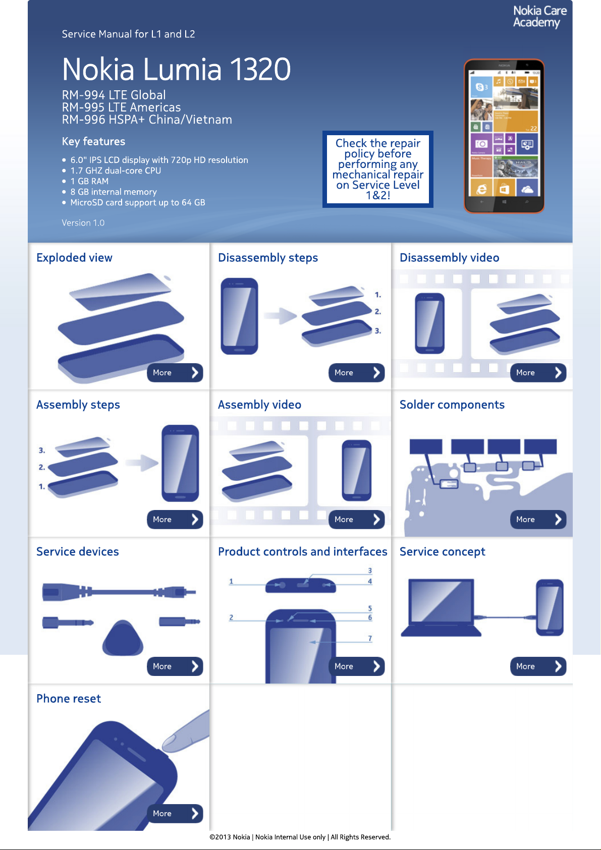
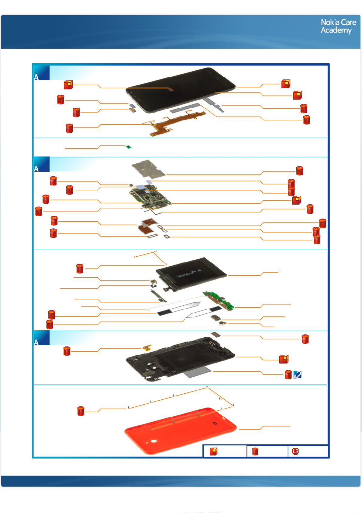
A-COVER ASSEMBLY
(I0001 - I0008)
1
TOUCH PANEL
I0001
EARPIECE ADHESIVE
I0005
EARPIECE
I0004
SIDE KEY FLEX
I0008
Exploded view
UI FRAME
I0003
DISPLAY MODULE
I0002
SUB BOARD ADHESIVE
I0007
DISPLAY FLEX ADHESIVE
I0006
ALS/PROX SENSOR
LIGHT SWAP PACKAGE
(I0010 - I0024)
2
FRONT CAMERA RUBBER
THERMAL PAD
TOP AV CONNECTOR SPONGE
BOTTOM AV CONNECTOR SPONGE
BOTTOM SHIELDING LID
TP CONNECTOR RUBBER
MAIN CAMERA
MAIN CAMERA SPONGE
B2B BRACKET
RF CABLE
LONG BATTERY ADHESIVE
SHORT BATTERY ADHESIVE
D-COVER ASSEMBLY
I0033 - I0035)
3
FLASH LED FLEX
I0009
I0019
I0021
I0014
I0013
I0011
I0018
SCREW
I0027
I0025
I0026
I0028
I0032
I0029
I0030
I0035
TOP SHIELDING LID
I0012
THERMAL PAD
I0023
THERMAL PAD
I0022
LIGHT SWAP PWB
I0010
MB MAIN CAMERA SPONGE
I0020
SIDE KEY MB CONNECTOR RUBBER
I0017
DISPLAY CONNECTOR RUBBER
I0016
BATTERY CONNECTOR RUBBER
I0015
BATTERY
I0031
SUB BOARD PWB
I0038
IHF SPEAKER
I0037
VIBRA
I0036
IHF SPEAKER ADHESIVE
I0034
D-COVER
I0033
TYPE LABEL
I0024
SCREW
I0039
Only available
as assembly
©2013 Nokia | Nokia Internal Use only | All Rights Reserved.
BATTERY COVER
I0040
Not reuseable
after removal
Repair/swap
only in level 3
Service Manual Level 1 and 2
Nokia Lumia 1320
RM-994, RM-995, RM-996
Version 1.0
Disassembly steps
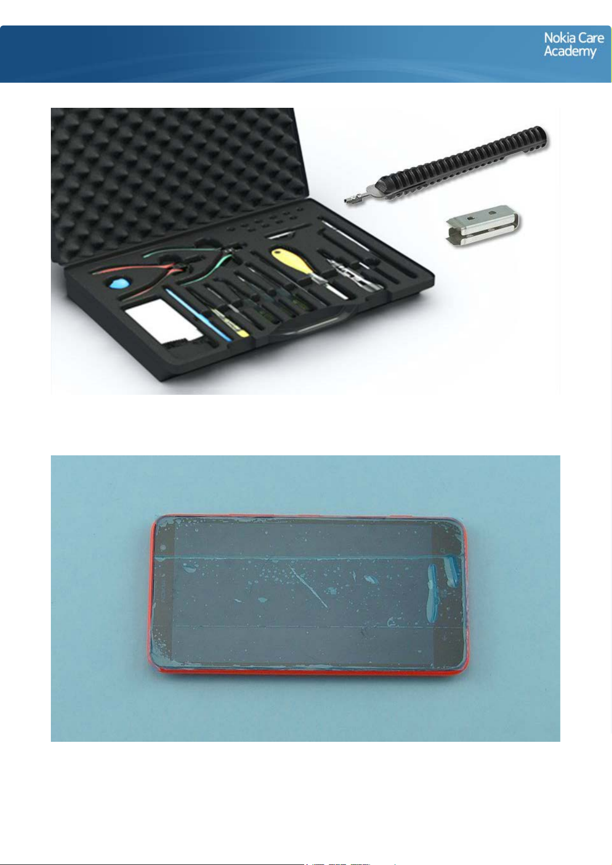
1) For disassembling you need the Nokia Standard toolkit version 2. You will also need the SS-231 rf
connector disassembly/assembly tool and the SS-305 camera removal tool.
2) Protect the TOUCH PANEL with protective tape.
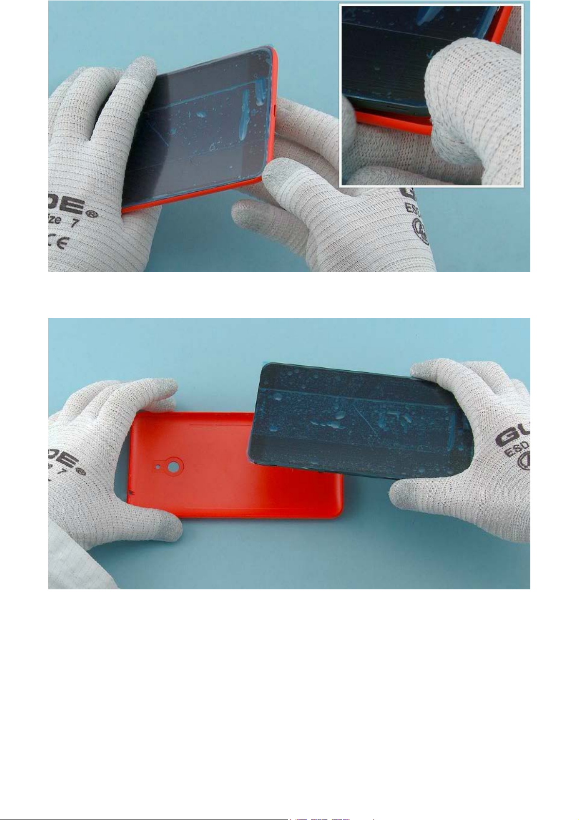
3) Push the BATTERY COVER from the shown corner to open it.
4) Remove the BATTERY COVER.
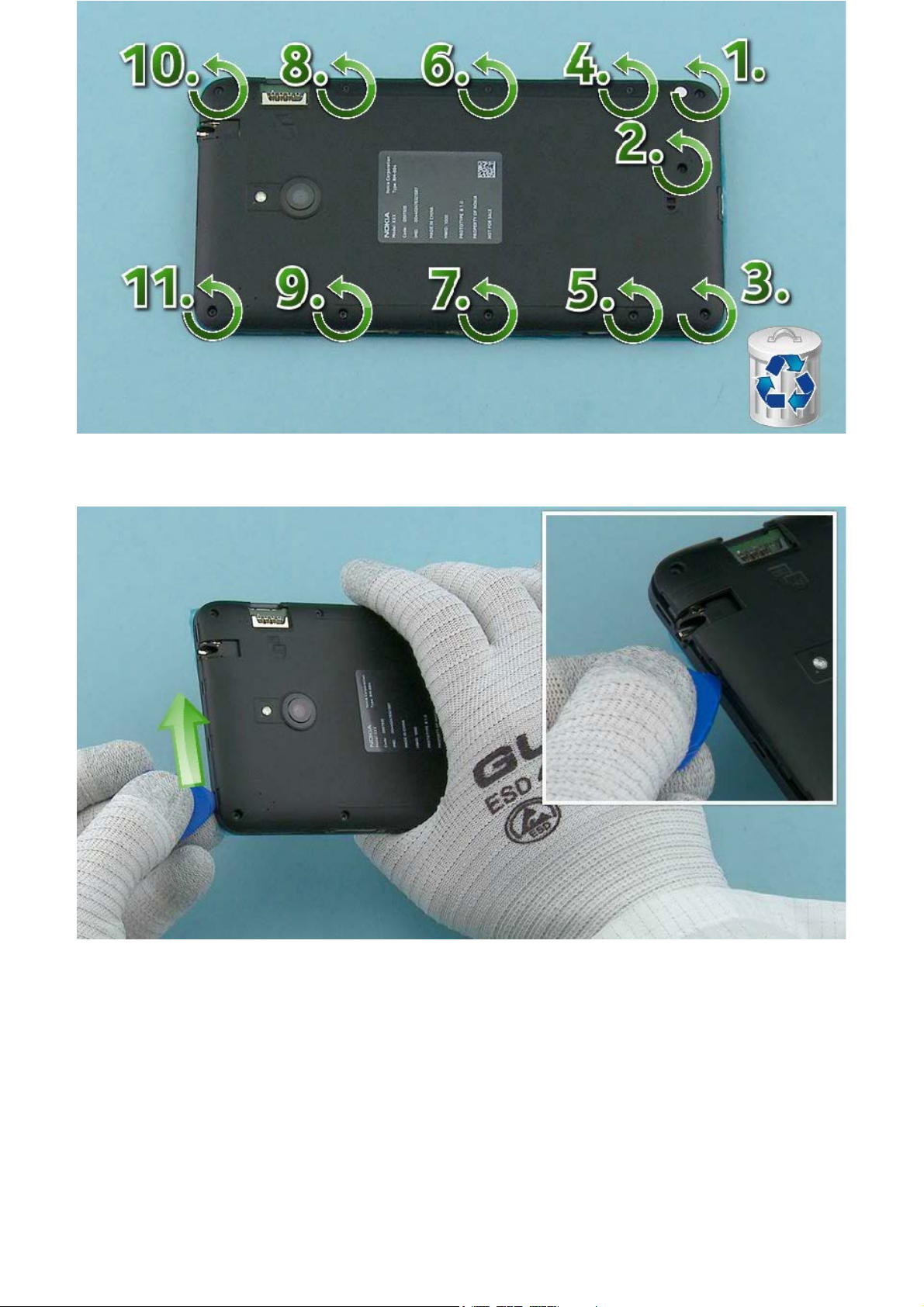
5) Unscrew the eleven Torx+ size 5 screws in the order shown. Do not use them again. Discard them.
6) Slide the SRT-6 to direction shown to release the top end of the D-COVER.
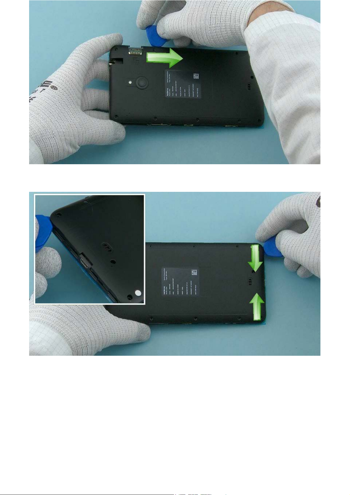
7) Open the left side of the D-COVER by sliding the SRT-6 to direction shown.
8) The bottom end of the D-COVER can be released by sliding the SRT-6 from both corners towards the
USB connector as shown.
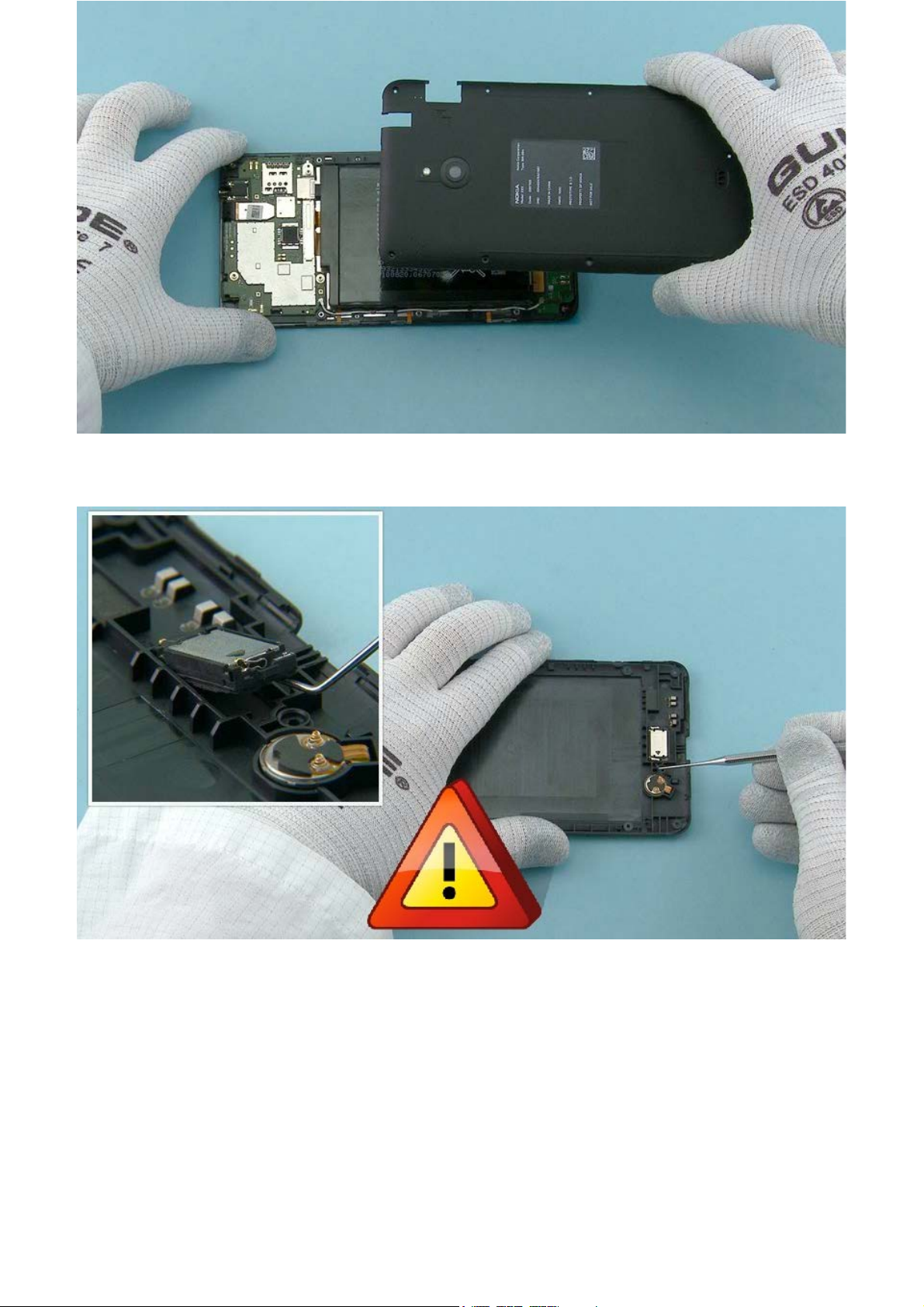
9) The D-COVER can now be separated.
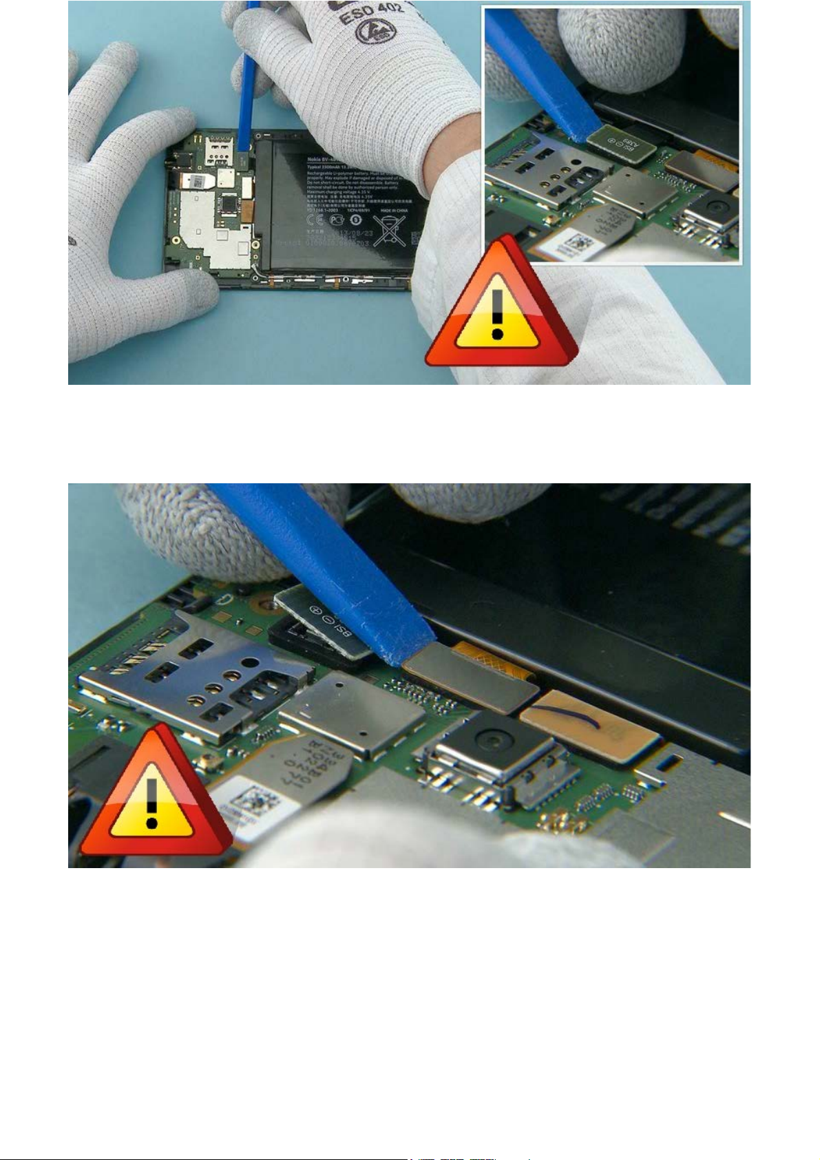
10) Use the dental tool to lift up the IHF SPEAKER.
Be careful not to injure yourself with the sharp end of the dental tool!
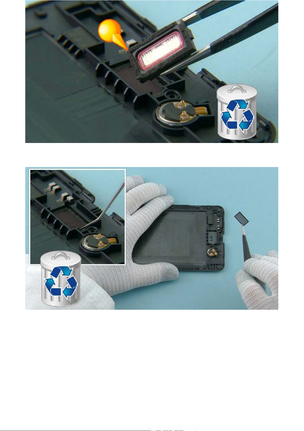
11) Remove the IHF SPEAKER. Remove the adhesive remains from the IHF SPEAKER and discard them.
12) Use the dental tool to remove the IHF SPEAKER ADHESIVE from the D-COVER. Discard the IHF
SPEAKER ADHESIVE.
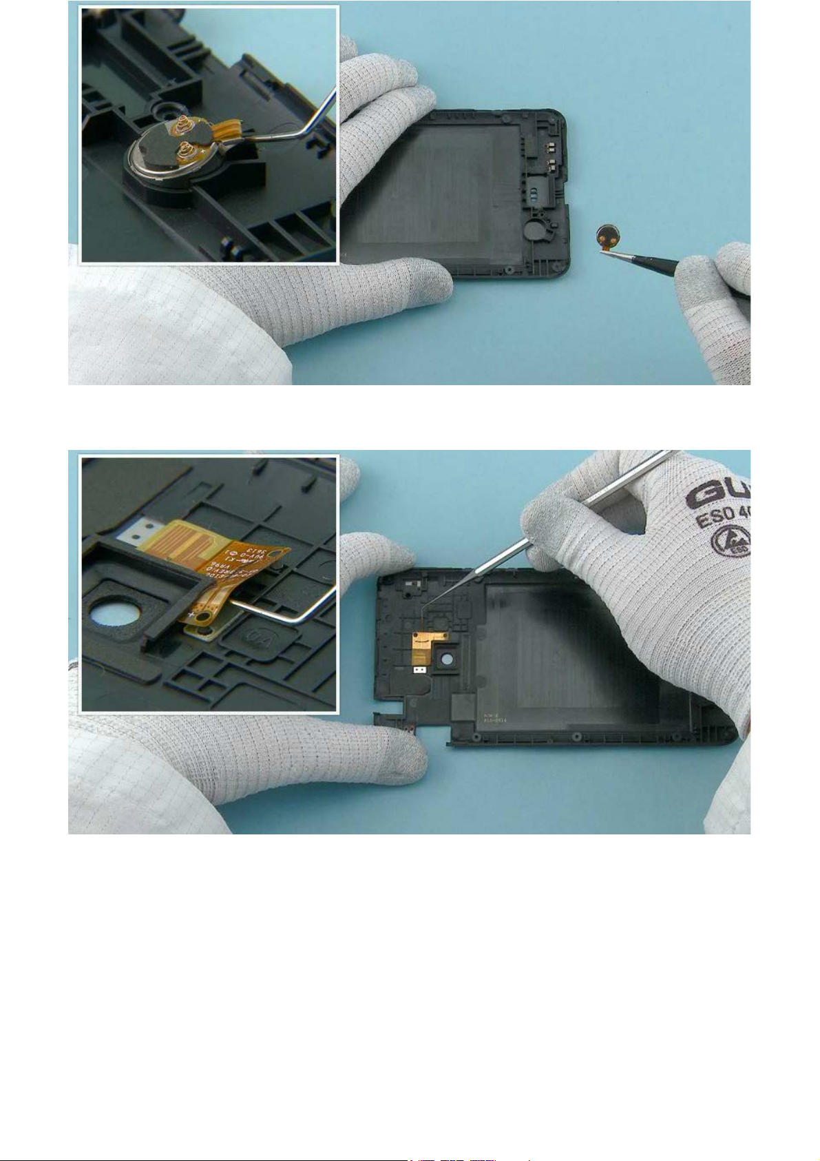
13) Release the VIBRA with the dental tool. Remove the VIBRA.
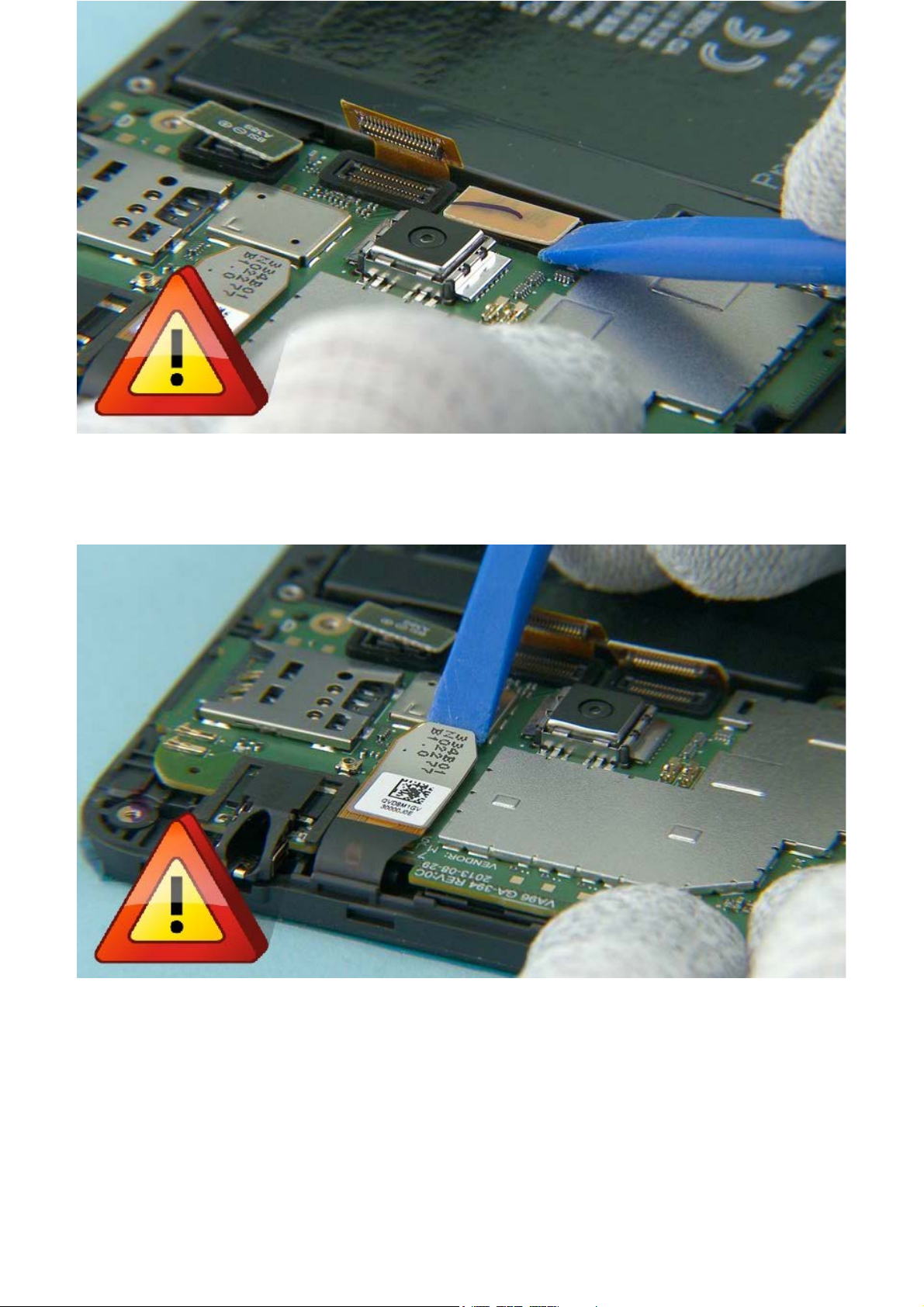
14) Release the FLASH LED FLEX with the dental tool.
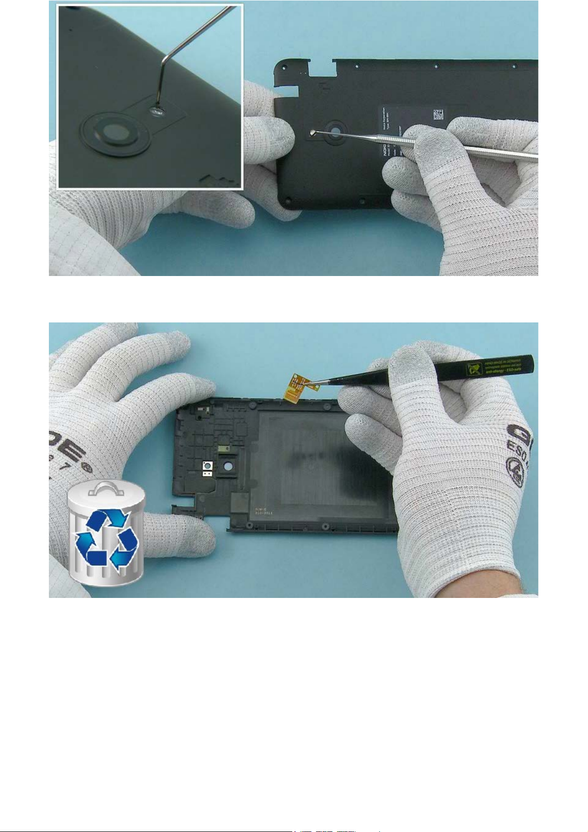
15) Push from the shown hole with the dental tool to release the FLASH LED FLEX.
16) Remove the FLASH LED FLEX. Do not use it again. Discard it.
17) Use the SS-231 to open the RF CABLE connector. Place the SS-231 on top of the cable and slide it to
the direction shown to lock it to the cable connector. Lift up the SS-231 to open the connector.
Be careful not to damage the connector or any components nearby!
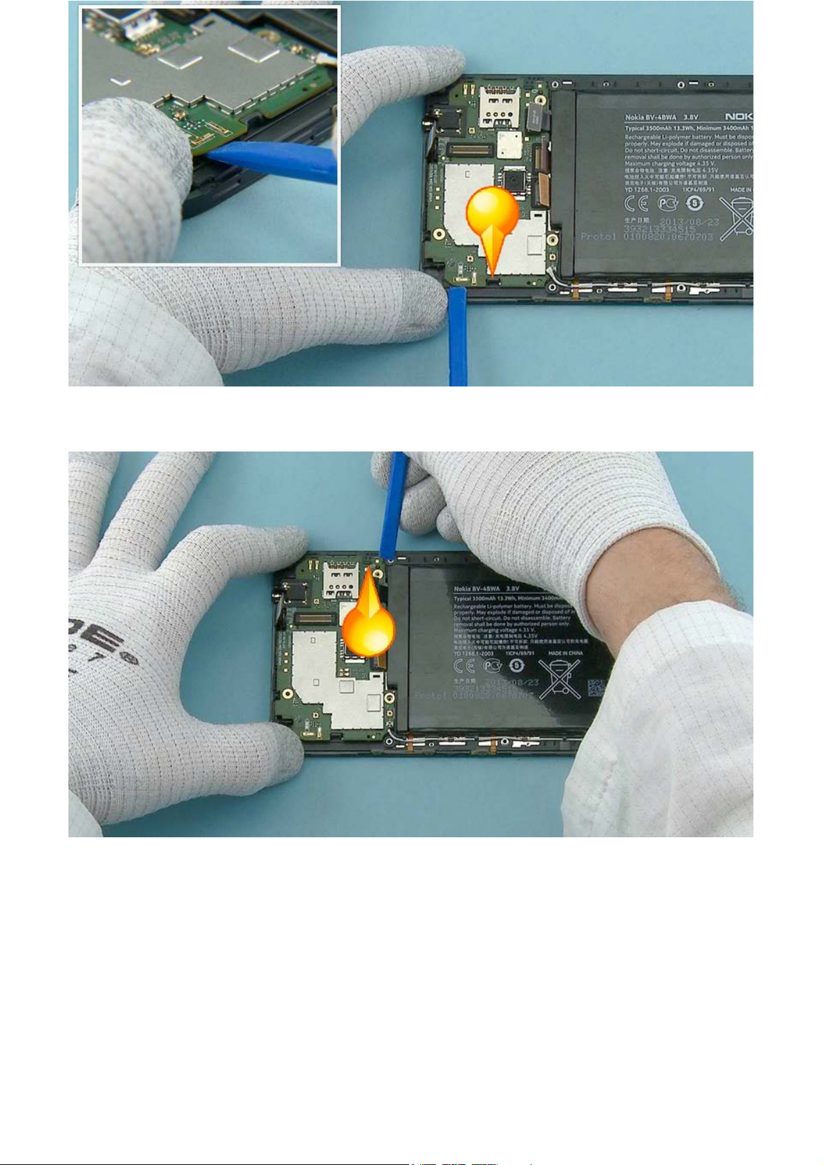
18) Open also the other end of the RF CABLE with the SS-231.
Be careful not to damage the connector or any components nearby!
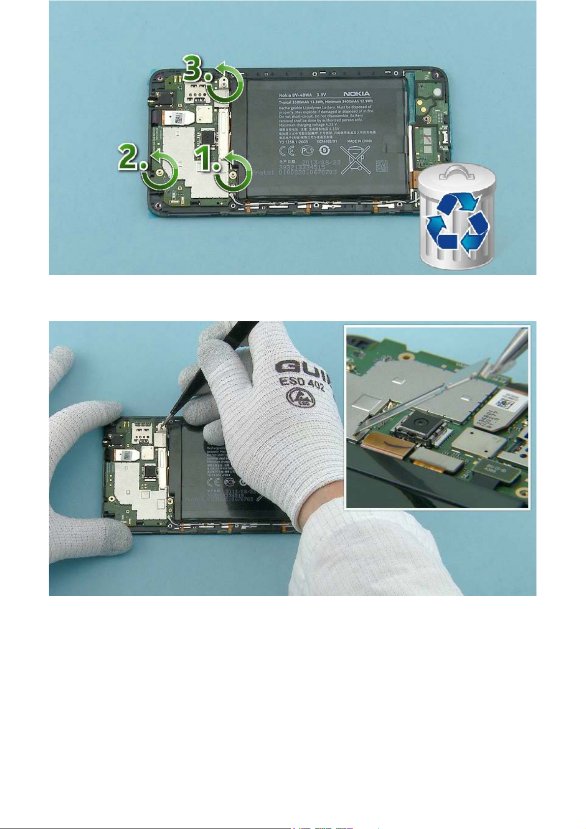
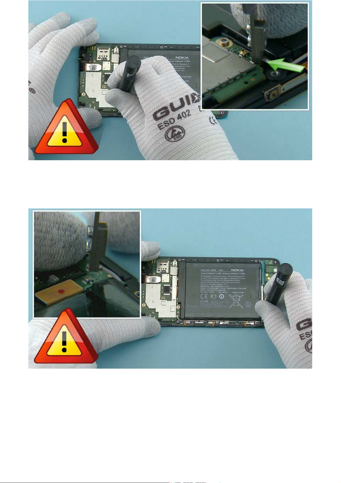
19) Unscrew the three Torx+ size 5 screws in the order shown. Do not use them again. Discard them.
20) Lift up the B2B BRACKET and remove it.
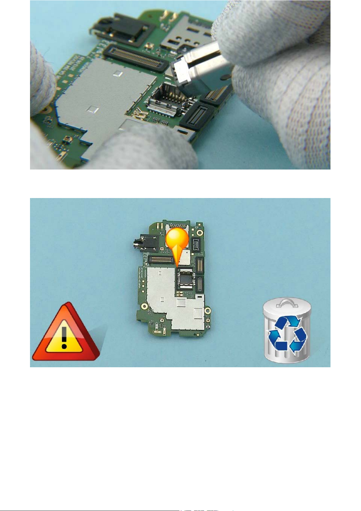
21) Use the SS-93 to open the BATTERY CONNECTOR.
Be careful not to damage the connector or any components nearby!
22) Use the SS-93 to open the SIDE KEY FLEX connector.
Be careful not to damage the connector or any components nearby!
23) Use the SS-93 to open the DISPLAY connector.
Be careful not to damage the connector or any components nearby!
24) Use the SS-93 to open the TOUCH FLEX connector.
Be careful not to damage the connector or any components nearby!
25) Use the SS-93 to release the ENGINE BOARD from the shown hook holding it.
26) Release also the second hook holding the ENGINE BOARD.
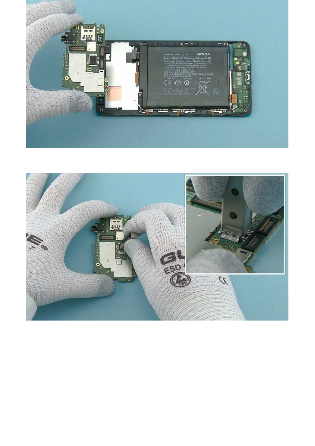
27) The ENGINE BOARD can now be separated.
28) Use the SS-305 tool to release the CAMERA.
29) Remove the CAMERA.
30) Use the dental tool to remove the shown MAIN BOARD MAIN CAMERA SPONGE. Do not use it again.
Discard it.
Be careful not to damage the ENGINE BOARD!
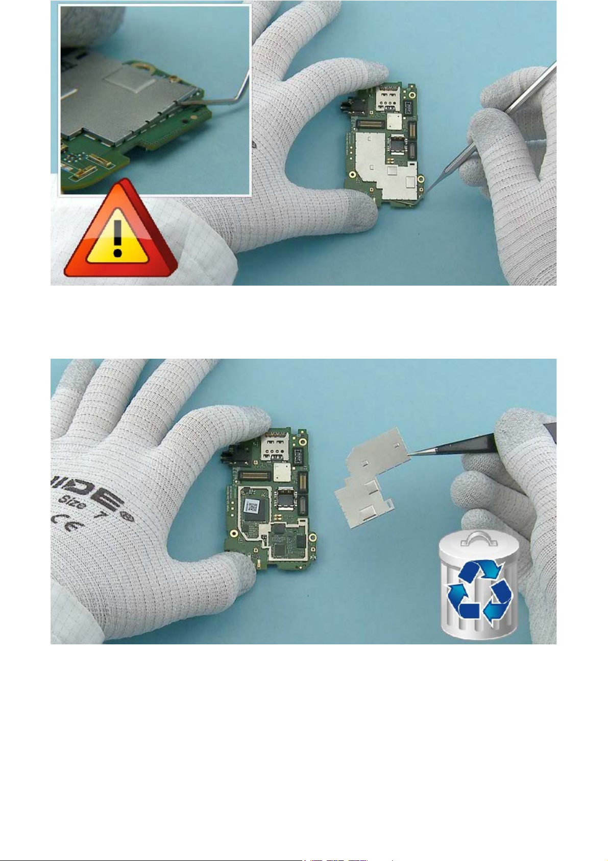
31) Lever out the BOTTOM SHIELDING LID from all sides with the dental tool.
Be careful not to damage the ENGINE BOARD!
32) Remove and discard the BOTTOM SHIELDING LID.

33) Release and remove the SIDE KEY connector rubber with the dental tool. Do not use it again. Discard
it.
When releasing the rubbers, be careful not to damage the ENGINE BOARD!
34) Release and remove the BATTERY connector rubber with the dental tool. Do not use it again. Discard
it.

35) Release and remove the TOUCH PANEL connector rubber with the dental tool. Do not use it again.
Discard it.
36) Release the BOTTOM AV CONNECTOR SPONGE with the dental tool. Do not use it again. Discard it.

37) Use the dental tool to remove the shown TOP AV CONNECTOR SPONGE. Do not use it again. Discard
it.
Be careful not to damage the ENGINE BOARD!
38) Remove and discard the FRONT CAMERA RUBBER.

39) Lever out the TOP SHIELDING LID from all sides with the dental tool.
Be careful not to damage the ENGINE BOARD!
40) Remove and discard the TOP SHIELDING LID.

41) Remove and discard the shown THERMAL PAD.
42) Remove and discard the shown THERMAL PAD.

43) Remove and discard the shown THERMAL PAD.
44) To remove the BATTERY the two shown BATTERY ADHESIVE tabs needs to be pulled directly to the
directions shown. Do not use the adhesives again. Discard them.

45) Lift up and remove the BATTERY.
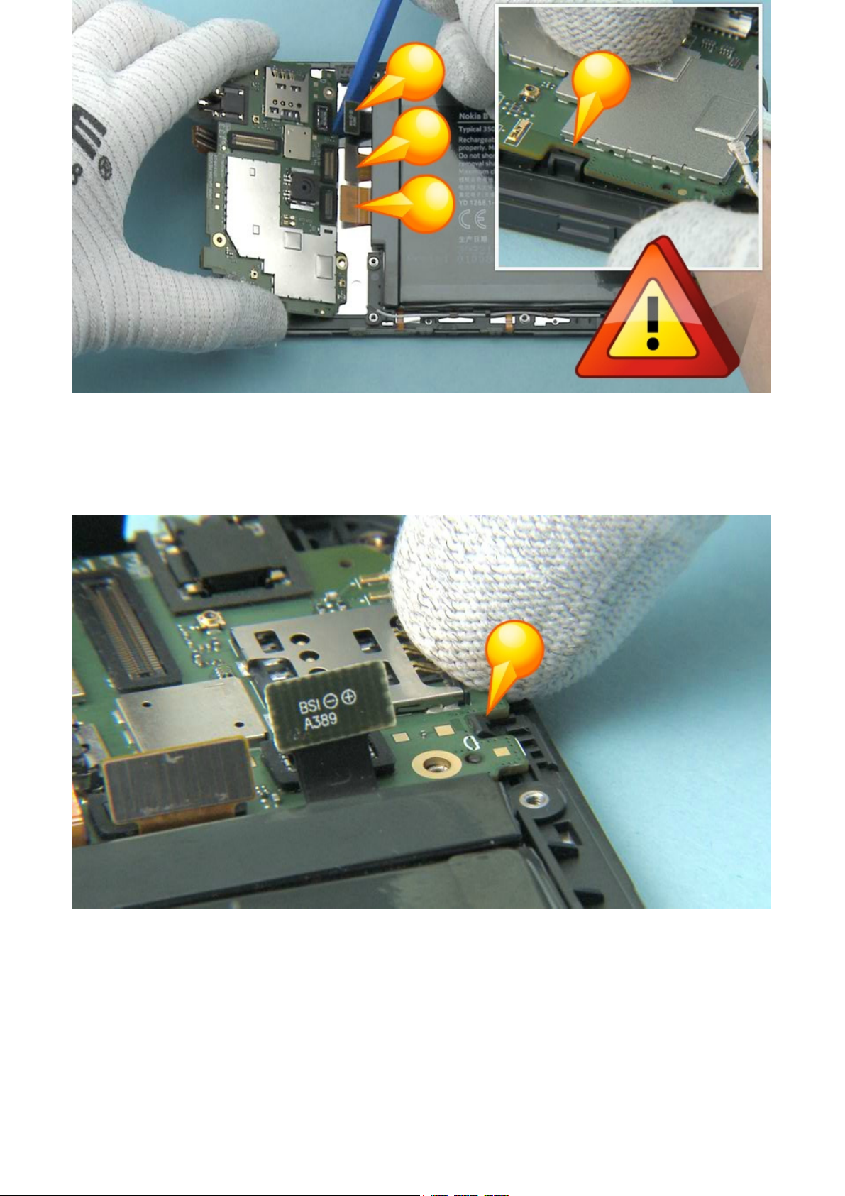
46) Release the RF CABLE from the hooks and remove it.

47) Use the SS-93 to open the SIDE KEY FLEX connector.
Be careful not to damage the connector or any components nearby!
48) To release the adhesive holding the SUB BOARD PWB, insert the SS-93 to the place shown and slide it
carefully to the direction shown.
Be careful not to damage the components underneath!

49) Lift up and remove the SUB BOARD PWB.
50) Remove and discard the SUB BOARD ADHESIVE.

51) Use the dental tool to lever up the ALS/PROXIMITY SENSOR.
Be careful not to damage the ALS/PROXIMITY SENSOR!
52) Remove the ALS/PROXIMITY SENSOR.

53) Remove the adhesive remains.
54) Release the EARPIECE with the dental tool.

55) Remove and discard the EARPIECE.
56) Remove and discard the EARPIECE ADHESIVE.

57) Start to release the SIDE KEY FLEX from the shown place with the SS-93.
58) Continue the removal of the SIDE KEY FLEX from the opposite side.
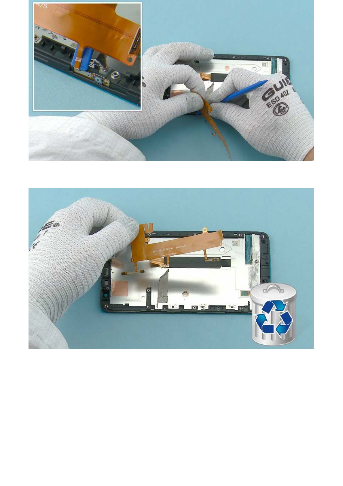
59) Release also the SIDE KEY FLEX side key parts.
60) Remove and discard the SIDE KEY FLEX.

61) Remove all the adhesive remains from the UI FRAME.
62) The Nokia Lumia 1320 disassembly procedure is complete.
-END OF DISASSEMBLY-
©2013 Nokia | Nokia Internal Use only | All Rights Reserved.

Service Manual Level 1 and 2
V
0
A
Nokia Lumia 1320
RM-994, RM-995, RM-996
ersion 1.
ssembly steps
1) For assembling you need the Nokia Standard toolkit version 2. You will also need the SS-231 rf
connector disassembly/assembly tool.
2) Use tweezers to peel off the protective film from the VIBRA.

3) Align the VIBRA with tweezers. Press gently with the SS-93 to activate the adhesive.
4) Use tweezers to pick a new IHF SPEAKER ADHESIVE and place it into the IHF SPEAKER gavity. Remove the
protective film from the IHF SPEAKER ADHESIVE.

5) Unwrap a new IHF SPEAKER with tweezers. Place the IHF SPEAKER into its slot. Make sure the IHF
SPEAKER is aligned correctly. The triangle should point towards the VIBRA.
6) Press gently with the SS-93 to activate the adhesive. Avoid touching the springs.

7) Use tweezers to remove the protective tapes from a new FLASH LED FLEX . Align the FLASH LED FLEX
with tweezers.
8) Use the shown guidings when aligning the FLASH LED FLEX. Secure the flex with the SS-93.

9) Unwrap new THERMAL PADS with tweezers. Place the THERMAL PADS with tweezers in shown places.
10) Place a new TOP SHIELDING LID with tweezers. Make sure all the clips are secured properly.

11) Attach the FRONT CAMERA RUBBER with tweezers.
12) Place a new BOTTOM SHIELDING LID with tweezers. Make sure all the clips are secured properly.

13) Use tweezers to pick a new AV CONNECTOR SPONGEs. Place the BOTTOM AV CONNECTOR SPONGE
around the AV CONNECTOR as shown.
Remember to place the TOP AV CONNECTOR SPONGE around the AV CONNECTOR on the other side of the
ENGINE BOARD.
14) Use tweezers to pick new CONNECTOR RUBBERs. Place the RUBBERs carefully around the TOUCH
PANEL CONNECTOR, BATTERY CONNECTOR, DISPLAY CONNECTOR and the SIDE KEY CONNECTOR.

15) Unwrap a new CAMERA. Place the CAMERA to the camera socket with tweezers. Note the correct
alignment.
16) Press gently with the SS-93 to secure the CAMERA properly.

17) Use tweezers to pick a new CAMERA SPONGE. Place the CAMERA SPONGE on top of the CAMERA.
18) Place also the MB MAIN CAMERA SPONGE around the CAMERA SOCKET.

19) Use tweezers to pick a new SUB BOARD ADHESIVE. Align the SUB BOARD ADHESIVE with tweezers to
the A-COVER.
20) Press the SUB BOARD ADHESIVE gently with fingers to activate the adhesive.

21) Use tweezers to peel off the protective film from both BATTERY ADHESIVES. Then place them on the
A-COVER as shown.
22) Remove the protective films from the SIDE KEY FLEX.

23) Attach the shown key parts of the flex first to the A-COVER.
24) Use the guidings when aligning the flex.

25) Bend the flex carefully onto the A-COVER. Press gently with fingers to activate the adhesive.
26) Use tweezers to pick a new EARPIECE ADHESIVE. Place it into the EARPIECE gavity. Remove the
protective film with tweezers.

27) Unwrap a new earpiece and attach it with tweezers.
28) Press gently with the SS-93 to activate the adhesive.

29) Use tweezers to assemble the ALS/PROXIMITY SENSOR. Make sure it is attached properly.
30) Peel off the protective film from the SUB BOARD ADHESIVE. Place the SUB BOARD to the A-COVER.
While aligning the SUB BOARD be careful not to damage the SIDE KEY FLEX or connector.

31) Then slide the SUB BOARD into its place and make sure these clips are secured.
32) Check also that the SUB BOARD is aligned correctly.

33) Use the SS-93 to connect the SIDE KEY FLEX CONNECTOR.
Be careful not to damage the connectors or any nearby components.
34) Place the SS-231 on top of the RF cable connector. Press the SS-231 carefully to secure the
connector. Release the SS-231 by sliding it towards the cable.
Be careful not to damage the connector or any components nearby.

35) Use the SS-93 to route the RF CABLE and place it under the hooks.
36) Use tweezers to peel off the protective film from both BATTERY ADHESIVES.

37) Place the BATTERY into the A-COVER ASSEMBLY. Press the BATTERY with fingers to secure it properly.
38) Peel off this protective film from the BATTERY ADHESIVE. Bend the adhesive on top of the BATTERY.
39) Place the ENGINE BOARD to the A-COVER ASSEMBLY. Check that the ENGINE BOARD goes under this
clip.
While aligning the ENGINE BOARD be careful not to damage the connectors.
40) The clip on the other side must be secured also.

41) Place the SS-231 on top of the RF cable connector. Press the SS-231 carefully to secure the
connector. Release the SS-231 by sliding it towards the cable.
Be careful not to damage the connector or any components nearby.
Make sure the RF CABLE is routed correctly and placed under the clips.
42) Use the SS-93 to carefully connect the TOUCH PANEL CONNECTOR, the SIDE KEY CONNECTOR, the
DISPLAY CONNECTOR and the BATTERY CONNECTOR.
Be careful not to damage the connector or any components nearby.

43) Use tweezers to attach the B2B BRACKET. Fasten the shown clip first and then lower down the other
end.
44) Fasten the three TORX+ size 5 screws in the order shown to the torque of 8 Ncm.

45) Combine the D-COVER ASSEMBLY and the A-COVER ASSEMBLY. Press the edges slightly to attach all
the clips correctly.
46) Fasten the eleven TORX+ size 5 screws in the order shown to the torque of 12 Ncm.

47) Align the bottom end of the A-COVER ASSEMBLY first to the BATTERY COVER.
48) Then put down the other end and press slightly to attach the BATTERY COVER properly.
The Nokia Lumia 1320 assembly procedure is complete.
-END OF ASSEMBLY-
©2013 Nokia | Nokia Internal Use only | All Rights Reserved.

Service Manual Level 1 and 2
Nokia Lumia 1320
RM-994, RM-995, RM-996
Version 1.0
TOP
Solder components
BOTTOM
RF ANT
Spring
SP1603
Flash LED
Spring
S2601
S2600
RF ANT
Spring
F300
USB
Fuse
V2423
RF ANT
Spring
S400
S401
RF ANT
Spring
©2013 Nokia | Confidential | All Rights Reserved.

Service Manual Level 1 and 2
V
0
Nokia Lumia 1320
RM-994, RM-995, RM-996
ersion 1.
Service devices
CA-190CD Service cable AC-20,
AC-50c (inbox charger for China only),
AC-60
SS-231 RF cable opening tool Nokia Standard Toolkit (v2)
For more information, refer to the Service
Bulletin (SB-011) on Nokia Online. Supplier or
manufacturer contacts for tool re-order can be
found in “Recommended service equipment”
document on Nokia Online.
SS-305 Camera removal tool
©2013 Nokia | Nokia Internal Use only | All Rights Reserved.

Service Manual Level 1 and 2
Nokia Lumia 1320
RM-994, RM-995, RM-996
Version 1.0
Product controls and interfaces
1
2
4
3
1 — 3.5 mm AHJ connector
2 — Earpiece
3 — Ambient light &
proximity sensor
4 — Front camera
5 — Touch screen
6 — Start key
7 — Back key
8 — Search key
9 — Microphone
5
10 — Micro-USB connector
11 — LED flash
12 — Camera
13 — Volume keys
14 — Power/lock key
15 — Camera key
6
7
8
9
10
16 — Loudspeaker
17 — BT/GPS/Wi-Fi antenna
18 — MIMO antenna
19 — NFC area
20 — Cellular antenna
17
12
11
18
19
13
14
15
16
20
©2013 Nokia | Nokia Internal Use only | All Rights Reserved.

Service Manual Level 1 and 2
Nokia Lumia 1320
RM-994, RM-995, RM-996
Version 1.0
Flashing concept
Service concept
Service
software
CA-101
Note: Charged
battery is
mandatory
Transceiver with
embedded battery
©2013 Nokia | Nokia Internal Use only | All Rights Reserved.

Service Manual Level 1 and 2
Nokia Lumia 1320
RM-994, RM-995, RM-996
Version 1.0
Phone reset
Hardware reset
If the phone hardware is jammed, you should first
recommend that the consumer performs a hardware
reset. The hardware reset does not reset the
Windows Live ID or remove any consumer data.
Because the consumer cannot remove the battery to
reset the phone the phone has a special electronic
circuit which cuts the phone power when the volume
down and the power key is pressed for 10 seconds.
To perform the hardware reset press the Volume
down and the Power key and hold them for 10
seconds. The phone screen will turn black (phone is
off). Then press the Power key to turn on the phone.
Note that the Nokia Lumia 1320 also supports a 1key reset. To perform the 1-key hardware reset
press and hold the Power key for 10 seconds.
Software / operating system (OS) reset
The software / operating system (OS) reset returns the phone to its
out-of-the-box state. Note that this procedure erases all consumer
data! Always first try to perform a hardware reset.
To perform software reset tap Settings > About > reset your phone
©2013 Nokia | Nokia Internal Use only | All Rights Reserved.
 Loading...