

Page 1

7368 ISAM ONT G-240W-C Product Guide
R05.05.01 | December 2016 | 3FE 46690 AAAA TCZZA | Edition 01
7368 Intelligent Services Access
Manager ONT
7368 ISAM ONT G-240W-C Product
Guide
Edition 01
Issue: 01
Nokia — Proprietary and confidential
Use pursuant to applicable agreements
Page 2

7368 ISAM ONT G-240W-C Product Guide
R05.05.01 | December 2016 | 3FE 46690 AAAA TCZZA | Edition 01
Nokia is a registered trademark of Nokia Corporation. Other products and company
names mentioned herein may be trademarks or tradenames of their respective
owners.
The information presented is subject to change without notice. No responsibility is
assumed for inaccuracies contained herein.
© 2016 Nokia.
Contains proprietary/trade secret information which is the property of Nokia and must
not be made available to, or copied or used by anyone outside Nokia without its
written authorization. Not to be used or disclosed except in accordance with
applicable agreements.
2
Edition 01 Issue: 01
Page 3

7368 ISAM ONT G-240W-C Product Guide Preface
R05.05.01 | December 2016 | 3FE 46690 AAAA TCZZA | Edition 01
1Preface
This preface provides general information about the documentation set for optical
network terminals (ONTs).
1.1 Scope
This documentation set provides information about safety, features and functionality,
ordering, hardware installation and maintenance, and software installation
procedures for the current release.
1.2 Audience
This documentation set is intended for planners, administrators, operators, and
maintenance personnel involved in installing, upgrading, or maintaining the ONTs.
1.3 Required knowledge
The reader must be familiar with general telecommunications principles.
1.4 Acronyms and initialisms
The expansions and optional descriptions of most acronyms and initialisms appear
in the glossary.
1.5 Assistance and ordering phone numbers
Nokia provides global technical support through regional call centers. Phone
numbers for the regional call centers are available at the following URL:
http://support.alcatel-lucent.com
For ordering information, contact your Nokia sales representative.
.
Issue: 01 Edition 01 3
Page 4

Preface
R05.05.01 | December 2016 | 3FE 46690 AAAA TCZZA | Edition 01
7368 ISAM ONT G-240W-C Product Guide
1.6 Nokia quality processes
Nokia’s ONT quality practices are in compliance with TL 9000 requirements. These
requirements are documented in the Fixed Networks Quality Manual
3FQ-30146-6000-QRZZA. The quality practices adequately ensure that technical
requirements and customer end-point requirements are met. The customer or its
representatives may be allowed to perform on-site quality surveillance audits, as
agreed upon during contract negotiations
1.7 Safety information
For safety information, see the appropriate safety guidelines chapter.
1.8 Documents
Documents are available using ALED or OLCS.
Procedure 1 To download a ZIP file package of the customer documentation
1 Navigate to http://support.alcatel-lucent.com and enter your user name and password. If you
are a new user and require access to this service, please contact your Nokia sales
representative.
2 From the Technical Content for drop-down menu, choose the product.
3 Click on Downloads: Electronic Delivery.
4 Choose Documentation from the drop-down menu and click Next.
5 Select the image from the drop-down menu and click Next.
6 Follow the on-screen directions to download the file.
4
Edition 01 Issue: 01
Page 5
7368 ISAM ONT G-240W-C Product Guide Preface
R05.05.01 | December 2016 | 3FE 46690 AAAA TCZZA | Edition 01
Procedure 2 To access individual documents
Individual PDFs of customer documents are also accessible through the Nokia Customer Support
website.
1 Navigate to http://support.alcatel-lucent.com and enter your user name and password. If you
are a new user and require access to this service, please contact your Nokia sales
representative.
2 From the Technical Content for drop-down menu, choose the product.
3 Click on Manuals and Guides to display a list of customer documents by title and part
number. You can filter this list using the Release drop-down menu.
4 Click on the PDF to open or save the file.
1.9 Special information
The following are examples of how special information is presented in this document.
Danger — Danger indicates that the described activity or
situation may result in serious personal injury or death; for
example, high voltage or electric shock hazards.
Warning — Warning indicates that the described activity or
situation may, or will, cause equipment damage or serious
performance problems.
Caution — Caution indicates that the described activity or
situation may, or will, cause service interruption.
Note — A note provides information that is, or may be, of
special interest.
Issue: 01 Edition 01 5
Page 6

Preface
R05.05.01 | December 2016 | 3FE 46690 AAAA TCZZA | Edition 01
1.9.1 Procedures with options or substeps
When there are options in a procedure, they are identified by letters. When there are
required substeps in a procedure, they are identified by roman numerals.
Procedure 3 Example of options in a procedure
At step 1, you can choose option a or b. At step 2, you must do what the step indicates.
1 This step offers two options. You must choose one of the following:
a This is one option.
b This is another option.
2 You must perform this step.
7368 ISAM ONT G-240W-C Product Guide
Procedure 4 Example of required substeps in a procedure
At step 1, you must perform a series of substeps within a step. At step 2, you must do what the
step indicates.
1 This step has a series of substeps that you must perform to complete the step. You must
perform the following substeps:
i This is the first substep.
ii This is the second substep.
iii This is the third substep.
2 You must perform this step.
6
Edition 01 Issue: 01
Page 7

7368 ISAM ONT G-240W-C Product Guide Preface
R05.05.01 | December 2016 | 3FE 46690 AAAA TCZZA | Edition 01
1.10 Multiple PDF document search
You can use Adobe Reader Release 6.0 and later to search multiple PDF f iles for a
common term. Adobe Reader displays the results in a single display panel. The
results are grouped by PDF file, and you can expand the entry for each file.
Note — The PDF files in which you search must be in the same
folder.
Procedure 5 To search multiple PDF files for a common term
1 Open Adobe Acrobat Reader.
2 Choose Edit→Search from the Acrobat Reader main menu. The Search PDF panel appears.
3 Enter the search criteria.
4 Click on the All PDF Documents In radio button.
5 Select the folder in which to search using the drop-down menu.
6 Click on the Search button.
Acrobat Reader displays the search results. You can expand the entries for each document
by clicking on the + symbol.
Issue: 01 Edition 01 7
Page 8

Preface
R05.05.01 | December 2016 | 3FE 46690 AAAA TCZZA | Edition 01
7368 ISAM ONT G-240W-C Product Guide
8
Edition 01 Issue: 01
Page 9

7368 ISAM ONT G-240W-C Product Guide
R05.05.01 | December 2016 | 3FE 46690 AAAA TCZZA | Edition 01
Table of contents
1 Preface.............................................................................................3
1.1 Scope ..........................................................................................................3
1.2 Audience......................................................................................................3
1.3 Required knowledge....................................................................................3
1.4 Acronyms and initialisms.................. ... ... ... ... .... ... ... ... .... ... ... ........................3
1.5 Assistance and ordering phone numbers....................................................3
1.6 Nokia quality processes...............................................................................4
1.7 Safety information........................................................................................4
1.8 Documents ..................................................................................................4
1.9 Special information......................................................................................5
1.9.1 Procedures with options or substeps...........................................................6
1.10 Multiple PDF document search ...................................................................7
2 ETSI ONT safety guidelines.........................................................17
2.1 Safety instructions.....................................................................................17
2.1.1 Safety instruction boxes ............................................................................17
2.1.2 Safety-related labels..................................................................................18
2.2 Safety standards compliance ....................................................................19
2.2.1 EMC, EMI, and ESD compliance................................... ... ... ... ... .... ... ... ... ...19
2.2.2 Equipment safety standard compliance.....................................................19
2.2.3 Environmental standard compliance .........................................................20
2.2.4 Laser product standard compliance ..........................................................20
2.2.5 Resistibility requirements compliance .......................................................20
2.2.6 Acoustic noise emission standard compliance.................................... ... ...20
2.3 Electrical safety guidelines........................................................................20
2.3.1 Power supplies..........................................................................................21
2.3.2 Cabling ......................................................................................................21
2.3.3 Protective earth .........................................................................................21
2.4 ESD safety guidelines ......................................... ... ... .... ... ... ... ... .... ... ... ... ...21
2.5 Laser safety guidelines..............................................................................21
2.5.1 Laser classification....................................................................................22
2.5.1.1 Laser warning labels..................................................................................22
2.5.2 Transmit optical output..............................................................................24
2.5.3 Normal laser operation..............................................................................24
2.5.4 Location class............................................................................................25
2.6 Environmental requirements......................................................................25
3 ETSI environmental and CRoHS guidelines...............................27
3.1 Environmental labels.................................................................................27
3.1.1 Overview....................................................................................................27
3.1.2 Environmental related labels.....................................................................27
3.1.2.1 Products below Maximum Concentration Value (MCV) label....................27
3.1.2.2 Products containing hazardous substance s above Maximum
Concentration Value (MCV) label..............................................................28
3.2 Hazardous Substances Table (HST).........................................................29
3.3 Other environmental requirements............................................................29
Issue: 01 Edition 01 9
Page 10

7368 ISAM ONT G-240W-C Product Guide
R05.05.01 | December 2016 | 3FE 46690 AAAA TCZZA | Edition 01
3.3.1 ONT environmental requirements .............................................................29
3.3.2 Storage......................................................................................................29
3.3.3 Transportation ...........................................................................................30
3.3.4 Stationary use............................................................................................30
3.3.5 Thermal limitations ....................................................................................30
3.3.6 Material content compliance................................................... ... .... ... ... ... ...30
3.3.7 End-of-life collection and treatment...........................................................31
4 G-240W-C unit data sheet ............................................................33
4.1 G-240W-C part numbers and identification...............................................33
4.2 G-240W-C general description..................................................................35
4.2.1 Configuring the G-240W-C to function as a single port ONT ....................36
4.2.2 TR-069 support............................. .... ... ... ... ... .............................................36
4.2.3 TR-104 parameter extension support for voice service.............................37
4.2.4 TR-104 voice-related alarms.................................................................. ...37
4.2.5 TR-181 Wi-Fi objects adapted in TR-098.................. .... ... ... ... ... .... ... ... ... ...37
4.2.6 Mobile offload support............................................................... .... ... ... ... ...38
4.2.7 Bridged Residential Gateway (BRG) support............................................39
4.2.8 Support for soft GRE tunnels.....................................................................39
4.2.8.1 GRE...........................................................................................................39
4.2.8.2 Soft GRE ................................ ... ... .... .........................................................40
4.3 G-240W-C software and installation feature support.................................41
4.4 G-240W-C interfaces and interface capacity.............................................41
4.4.1 G-240W-C connections and components..................................................41
4.5 G-240W-C LEDs........................................................................................44
4.6 G-240W-C detailed specifications.............................................................45
4.7 G-240W-C GEM ports and T-CONTs........................................................46
4.8 G-240W-C performance monitoring statistics............................................47
4.9 G-240W-C functional blocks......................................................................49
4.10 G-240W-C standards compliance .............................................................51
4.10.1 Energy-related products standby and off modes compliance....................51
4.10.2 FCC statement .................................... ... ... ... .... ... ... ... .... ... ... ... ... .... ............52
4.10.3 FCC Radiation Exposure Statement .........................................................52
4.11 G-240W-C special considerations.............................................................52
4.11.1 Wi-Fi service..................................................... ... ... ... .... ... ... ... ... ................53
4.11.1.1 Wi-Fi physical features..............................................................................53
4.11.1.2 Wi-Fi standards and certifications ................................. ... ... ... ... .... ... ... ... ...53
4.11.1.3 Wi-Fi GUI features .. ... ... ... .... ... ... ... .... ... ... ... ... .... .........................................53
4.11.2 G-240W-C ONT considerations and limitations.........................................54
10
5 Install a G-240W-C indoor ONT ...................................................55
5.1 Purpose.....................................................................................................55
5.2 General......................................................................................................55
5.3 Prerequisites..............................................................................................55
5.4 Recommended tools............................... ... ... .... ... ... ... .... ... ... ......................55
5.5 Safety information......................................................................................56
5.6 Procedure..................................................................................................57
6 Replace a G-240W-C indoor ONT................................................61
6.1 Purpose.....................................................................................................61
6.2 General......................................................................................................61
Edition 01 Issue: 01
Page 11

7368 ISAM ONT G-240W-C Product Guide
R05.05.01 | December 2016 | 3FE 46690 AAAA TCZZA | Edition 01
6.3 Prerequisites..............................................................................................61
6.4 Recommended tools............................... ... ... .... ... ... ... .... ... ... ......................61
6.5 Safety information......................................................................................62
6.6 Procedure..................................................................................................63
7 Configure a G-240W-C indoor ONT.............................................67
7.1 General......................................................................................................67
7.2 HGU mode GUI configuration....................................................................67
7.2.1 Login..........................................................................................................67
7.2.2 Device and connection status....................................................................68
7.2.3 Network configuration................................................................................83
7.2.4 Security configuration..............................................................................103
7.2.5 Application configuration .........................................................................110
7.2.6 Maintenance............................................................................................115
7.2.7 RG troubleshooting counters...................................................................128
7.3 SFU mode configuration..........................................................................130
7.3.1 Switch from default HGU mode to SFU mode.........................................130
7.3.2 Login........................................................................................................132
7.3.3 Device and connection status..................................................................133
7.3.4 Maintenance............................................................................................134
8 ONT configuration file over OMCI.............................................139
8.1 Purpose...................................................................................................139
8.2 Supported configuration file types...........................................................139
8.2.1 Filename conventions..............................................................................141
8.3 ONT configuration file over OMCI ...........................................................141
Issue: 01 Edition 01 11
Page 12

7368 ISAM ONT G-240W-C Product Guide
R05.05.01 | December 2016 | 3FE 46690 AAAA TCZZA | Edition 01
12
Edition 01 Issue: 01
Page 13

7368 ISAM ONT G-240W-C Product Guide
R05.05.01 | December 2016 | 3FE 46690 AAAA TCZZA | Edition 01
List of figures
2 ETSI ONT safety guidelines.........................................................17
Figure 1 PSE certification. .......................................................................................19
Figure 2 Laser product label....................................................................................22
Figure 3 Laser classification label............................................................................23
Figure 4 Laser warning labels..................................................................................24
3 ETSI environmental and CRoHS guidelines...............................27
Figure 5 Products below MCV value label...............................................................28
Figure 6 Products above MCV value label .............................. .... ... ... ... ... .... ... ... ... ...28
Figure 7 Recycling/take back/disposal of product symbol.......................................31
4 G-240W-C unit data sheet ............................................................33
Figure 8 SoftGRE-based architecture......................................................................40
Figure 9 G-240W-C indoor ONT physical connections............................................42
Figure 10 G-240W-C ONT without fiber cover...........................................................42
Figure 11 G-240W-C ONT with fiber cover................................................................43
Figure 12 G-240W-C indoor ONT LEDs....................................................................44
Figure 13 Single-residence Wi-Fi ONT with Gigabit Ethernet and POTS and
without RF video........................................................................................49
Figure 14 G-240W-C ONT hardware block ...............................................................50
5 Install a G-240W-C indoor ONT ...................................................55
Figure 15 G-240W-C ONT with connections and key mounting holes ......................58
Figure 16 G-240W-C indoor ONT wall mounting bracket..........................................58
Figure 17 G-240W-C indoor ONT with wall mounting bracket attached....................59
6 Replace a G-240W-C indoor ONT................................................61
Figure 18 G-240W-C indoor ONT connections..........................................................63
7 Configure a G-240W-C indoor ONT.............................................67
Figure 19 Web login window................................... ... ... .... ... ... ... .... ... ... ... ... .... ... ... ... ...68
Figure 20 Device Information window........................................................................69
Figure 21 LAN status window....................................................................................70
Figure 22 WAN status window...................................................................................72
Figure 23 WAN status IPv6 window ..........................................................................73
Figure 24 Home networking information window.......................................................75
Figure 25 Optics module status window....................................................................76
Figure 26 LAN ports Statistics window......................................................................77
Figure 27 WAN ports statistics window .....................................................................78
Figure 28 WAN ports statistics message...................................................................78
Figure 29 WLAN ports statistics window ...................................................................79
Figure 30 WLAN ports statistics message.................................................................79
Figure 31 Voice Information window..........................................................................80
Figure 32 Call Log window for admin users, showing all call types...........................81
Figure 33 Call Log window for standard users, showing all call types.......................82
Figure 34 LAN network window.................................................................................84
Figure 35 LAN IPv6 network window.........................................................................86
Figure 36 WAN network window................................................................................88
Issue: 01 Edition 01 13
Page 14

7368 ISAM ONT G-240W-C Product Guide
R05.05.01 | December 2016 | 3FE 46690 AAAA TCZZA | Edition 01
Figure 37 WAN DHCP window..................................................................................89
Figure 38 WiFi 2.4G network window........................................................................91
Figure 39 WiFi 5G network window...........................................................................93
Figure 40 Routing network window............................................................................95
Figure 41 DNS network window ................................................................................96
Figure 42 TR-069 network window............................ ... .... ... ... ... .... ... ... ... ... .... ... ... ... ...97
Figure 43 GRE Tunnel window..................................................................................98
Figure 44 US Classifier Policy window.......................................................... ... ... ....100
Figure 45 US Classifier window........................................................ ... ... .................101
Figure 46 US Classifier Rules window.....................................................................102
Figure 47 Firewall window.......................................................................................103
Figure 48 MAC filter window....................................................................................105
Figure 49 IP filter window .................................... ... ... ... .... ... ... ... .... ... ... ... ... .... ... ... ... .106
Figure 50 URL Filter window ...................................................................................107
Figure 51 DMZ and ALG window.............................................................................108
Figure 52 Access Control window ...........................................................................109
Figure 53 Port forwarding window...........................................................................111
Figure 54 DDNS window .........................................................................................112
Figure 55 NTP window ............................................................................................113
Figure 56 USB storage window........................................................................ ... ... .114
Figure 57 UPnP and DLNA window.........................................................................115
Figure 58 Password window ... ... ... ... .... ... ... ... .... ... ... ... ... .... ... ... ... .... ... ... ... ... .... ... ... ... .116
Figure 59 Speed Test window................................................................... .... ... ... ... .117
Figure 60 LOID Config window................................................................................118
Figure 61 SLID configuration window............................... ... ... ... .... ... ... ... ... .... ... ... ... .119
Figure 62 Device management window...................................................................120
Figure 63 Backup and Restore window...................................................................121
Figure 64 Firmware upgrade window ......................................................................122
Figure 65 Reboot window........................................................................................123
Figure 66 Factory default window . ... .... ... ... ... ...........................................................124
Figure 67 Diagnose window ....................................................................................125
Figure 68 Log window..............................................................................................126
Figure 69 PPPoE Diagnostics window ....................................................................127
Figure 70 PPPoE diagnostics results ......................................................................128
Figure 71 RG Troubleshooting Counters window....................................................129
Figure 72 Web login window...................................... ... ...........................................132
Figure 73 Device Information window......................................................................133
Figure 74 Password window ... ... ... ... .... ... ... ... .... ... ... ... ... .... ... ... ... .... ... ... ... ... .... ... ... ... .135
Figure 75 LOID configuration window......................................................................136
Figure 76 SLID configuration window............................... ... ... ... .... ... ... ... ... .... ... ... ... .137
14
Edition 01 Issue: 01
Page 15

7368 ISAM ONT G-240W-C Product Guide
R05.05.01 | December 2016 | 3FE 46690 AAAA TCZZA | Edition 01
List of tables
2 ETSI ONT safety guidelines.........................................................17
Table 1 Safety labels..............................................................................................18
4 G-240W-C unit data sheet ............................................................33
Table 2 Identification of G-240W-C indoor ONTs...................................................33
Table 3 G-240W-C power supply...........................................................................34
Table 4 G-240W-C indoor ONT interface connection capacity ..............................41
Table 5 G-240W-C indoor ONT physical connections............................................43
Table 6 G-240W-C indoor ONT LEDs....................................................................44
Table 7 G-240W-C indoor ONT physical specifications.........................................45
Table 8 G-240W-C indoor ONT power consumption specifications.......................46
Table 9 G-240W-C indoor ONT environmental specifications................................46
Table 10 G-240W-C indoor ONT capacity for GEM ports and T-CONTs.................46
Table 11 Package P ONTs ONTENET performance monitoring statistics ... ... ... ... ...47
Table 12 Package P ONTs ONTL2UNI performance monitoring statistics..............47
Table 13 Package P ONTs PONONTTC, PONONTMCTC, PONONTTCHSI,
PONONTTCCES, PONONTTCFLOW, PONONTTCVOIP
performance monitoring statistics..............................................................48
Table 14 Package P ONTs PONONTTC aggregate performance monitoring
statistics.....................................................................................................48
Table 15 G-240W-C ONT considerations and limitations.........................................54
7 Configure a G-240W-C indoor ONT.............................................67
Table 16 Device Information parameters .................................................................69
Table 17 LAN status parameters..............................................................................71
Table 18 WAN status parameters ............................................................................72
Table 19 WAN status IPv6 parameters....................................................................74
Table 20 Home networking parameters ...................................................................75
Table 21 Optics module status parameters..............................................................76
Table 22 Voice Information parameters ...................................................................80
Table 23 Call Log parameters..................................................................................82
Table 24 LAN network parameters...........................................................................84
Table 25 LAN IPv6 network parameters...................................................................86
Table 26 WAN network parameters .........................................................................88
Table 27 WAN DHCP parameters............................................................................90
Table 28 WiFi 2.4G network parameters..................................................................91
Table 29 WiFi 5G network parameters.....................................................................94
Table 30 Routing network parameters .....................................................................95
Table 31 DNS network parameters..........................................................................96
Table 32 TR-069 network parameters.......................................................... ... ... ... ...97
Table 33 GRE Tunnel parameters............................................................................98
Table 34 US Classifier Policy parameters................ ... .... ... ... ... .... ... ... ... ... .... ... ... ... .100
Table 35 US Classifier parameters........................ ... ... .... ... ... ... .... ... ... ... ... .... ... ... ... .101
Table 36 US Classifier Rules parameters ............................. ... .... ... ... ... ... .... ... ... ... .102
Table 37 Firewall parameters.................................................................................104
Table 38 MAC filter parameters..............................................................................105
Issue: 01 Edition 01 15
Page 16

7368 ISAM ONT G-240W-C Product Guide
R05.05.01 | December 2016 | 3FE 46690 AAAA TCZZA | Edition 01
Table 39 IP filter parameters................................................................. ... .... ... ... ... .106
Table 40 URL Filter parameters.............................................................................107
Table 41 DMZ and ALG parameters ......................................................................108
Table 42 Access control parameters......................................................................110
Table 43 Port forwarding parameters.................... ... ... .... ... ... ... .... ... ... ... ... .... ... ... ... .111
Table 44 DDNS parameters...................................................................................112
Table 45 NTP parameters......................................................................................113
Table 46 USB storage parameters........................ ... ... .... ... ... ... .... ... ... ... ... .... ... ... ... .114
Table 47 Password parameters............................. ... ... .... ... ... ... .... ... ... ... ... .... ... ... ... .116
Table 48 LOID configuration parameters ...............................................................118
Table 49 SLID configuration parameters......................................................... ... ....119
Table 50 Device management parameters ............................................................120
Table 51 PPPoE diagnostics results parameters...................................................128
Table 52 RG Troubleshooting Counters parameters..............................................129
Table 53 Device Information parameters ...............................................................134
Table 54 Password parameters............................. ... ... .... ... ... ... .... ... ... ... ... .... ... ... ... .135
Table 55 SLID configuration parameters......................................................... ... ....137
8 ONT configuration file over OMCI.............................................139
Table 56 Supported configuration files...................................................................140
16
Edition 01 Issue: 01
Page 17
7368 ISAM ONT G-240W-C Product Guide ETSI ONT safety guidelines
R05.05.01 | December 2016 | 3FE 46690 AAAA TCZZA | Edition 01
2 ETSI ONT safety guidelines
This chapter provides information about the mandatory regulations that govern the
installation and operation of the optical network terminals (ONTs).
2.1 Safety instructions
This section describes the safety instructions that are provided in the ONT customer
documentation and on the equipment.
2.1.1 Safety instruction boxes
The safety instruction boxes are provided in the ONT customer documentation.
Observe the instructions to meet safety requirements.
The following is an example of the Danger box.
Danger — Possibility of personal injury.
The Danger box indicates that the described activity or situation may pose a threat
to personal safety. It calls attention to a situation or procedure which, if no t correctly
performed or adhered to, may result in death or serious physical harm.
Do not proceed beyond a Danger box until the indicated conditions are fully
understood and met.
The following is an example of the Warning box.
Warning 1 — Possibility of equipment damage.
Warning 2 — Possibility of data loss.
The Warning box indicates that the described activity or situation may, or will, cause
equipment damage, loss of data, or serious performance problems. It identifies a
possible equipment-damaging situation or provides essential informat ion to avoid the
degradation of system operations or data.
Do not proceed beyond a warning until the indicated conditions are fully understood
and met.
Issue: 01 Edition 01 17
Page 18
ETSI ONT safety guidelines
R05.05.01 | December 2016 | 3FE 46690 AAAA TCZZA | Edition 01
The following is an example of the Caution box.
The Caution box indicates that the described activity or situation may, or will, cause
service interruption.
Do not proceed beyond a caution until the indicated conditions are fully understood
and met.
The following is an example of the Note box.
The Note box provides information that assists the personnel working with ONTs. It
does not provide safety-related instructions.
7368 ISAM ONT G-240W-C Product Guide
Caution 1 — Possibility of service interruption.
Caution 2 — Service interruption.
Note — Information of special interest.
2.1.2 Safety-related labels
The ONT equipment is labeled with the specific safety instructions and compliance
information that is related to a variant of the ONT. Observe the instructions on the
safety labels.
Table 1 provides sample safety labels on the ONT equipment.
Table 1 Safety labels
Description Label text
ESD warning Caution: This assembly contains an electrostatic sensitive device.
Laser classification Class 1 laser product
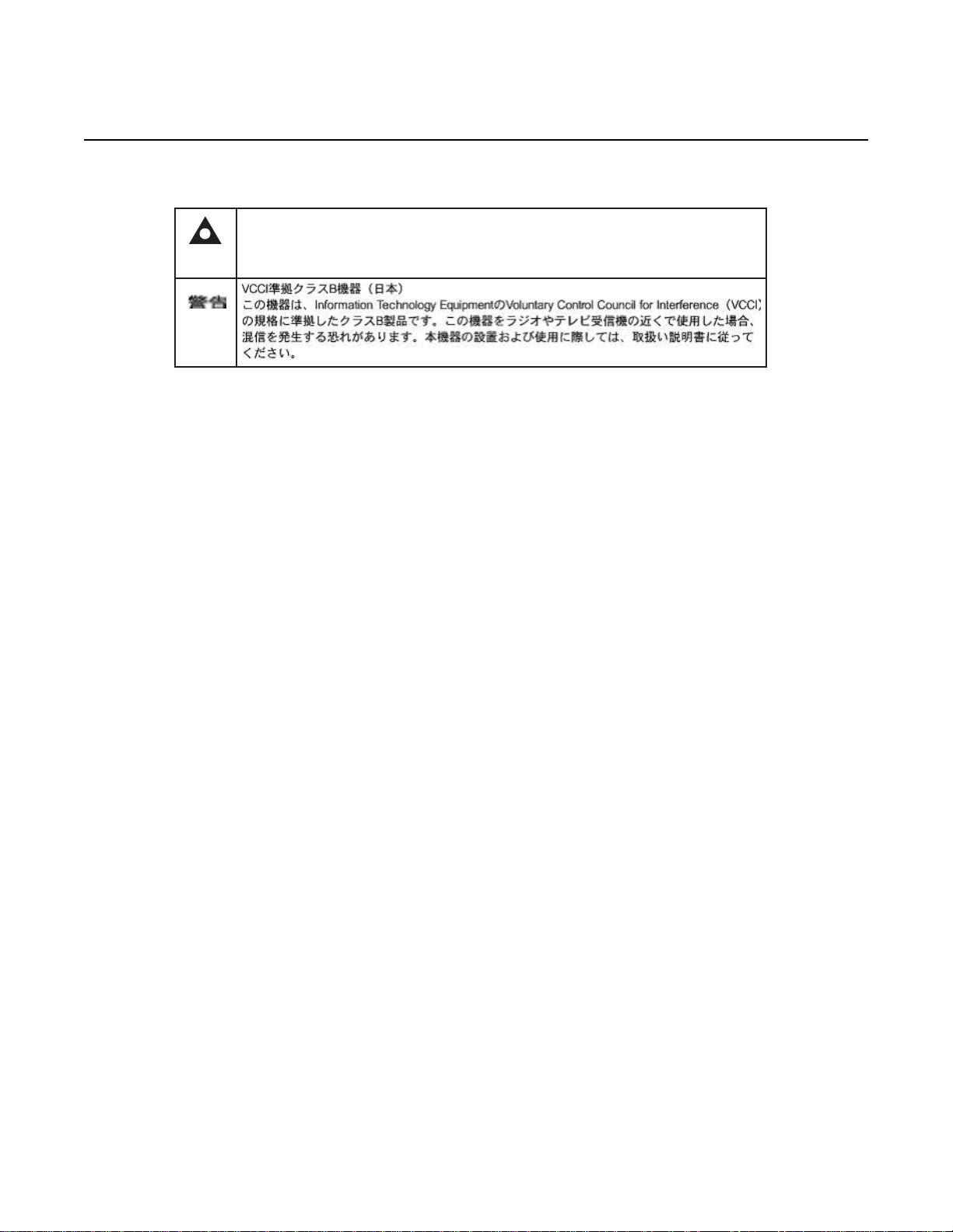
PSE marking These power supplies are Japan PSE certified and compliant with
Figure 1 shows the PSE certification.
Japan VCCI emissions standards.
18
Edition 01 Issue: 01
Page 19
7368 ISAM ONT G-240W-C Product Guide ETSI ONT safety guidelines
This is a Class B product based on the standard of the Voluntary Control Council for Interference
from Information Technology Equipment (VCCI). If this is used near a radio or television receiver in
a domestic environment, it may cause radio interference. Install and use the equipment according
to the instruction manual.
Warning
19841
R05.05.01 | December 2016 | 3FE 46690 AAAA TCZZA | Edition 01
Figure 1 PSE certification
2.2 Safety standards compliance
This section describes the ONT compliance with the European safety standards.
2.2.1 EMC, EMI, and ESD compliance
The ONT equipment complies with the following EMC, EMI, and ESD requirements:
• EN 300-328 v1.9.1 wide band data transmission standards for 2.4GHz bands
• EN 300-386 V1.5.1: Electromagnetic Compatibility and Radio Spectrum Matters
(ERM): Telecommunications Network Equipment; Electromagnetic Compatibility
(EMC) requirements; Electrostatic Discharge (ESD) requirements
• EN 55022 (2006): Class B, Information Technology Equipment, Radio
Disturbance Characteristics, limits and methods of measurement
• EN 55024 (2010): Information Technology Equipment, Immunity Characteristics,
limits and methods of measurement
• European Council Directive 2004/108/EC
• EN 300-386 V1.4.1: 2008
• EN 55022:2006 Class B (ONTs)
2.2.2 Equipment safety standard compliance
The ONT equipment complies with the requirements of EN 60950-1, Safety of
Information Technology Equipment for use in a restricted location (per R-269).
Issue: 01 Edition 01 19
Page 20

ETSI ONT safety guidelines
R05.05.01 | December 2016 | 3FE 46690 AAAA TCZZA | Edition 01
2.2.3 Environmental standard compliance
The ONT equipment complies with the EN 300 019 European environmental
standards.
2.2.4 Laser product standard compliance
For most ONTs, the ONT equipment complies with EN 60825-1 and IEC 60825-2 for
laser products. If there is an exception to this compliance regulation, you can find this
information in the standards compliance section of the unit data sheet in this Product
Guide.
2.2.5 Resistibility requirements compliance
7368 ISAM ONT G-240W-C Product Guide
The ONT equipment complies with the requirements of ITU Recommendation K.21
for resistibility of telecommunication equipment installed in customer premises to
over voltage and overcurrents.
2.2.6 Acoustic noise emission standard compliance
The ONT equipment complies with EN 300 753 acoustic noise emission limit and test
methods.
2.3 Electrical safety guidelines
This section provides the electrical safety guidelines for the ONT equipment.
Note 1 — The ONTs comply with the U.S. National Electrical
Code. However, local electrical authorities have jurisdiction
when there are differences between the local and U.S.
standards.
Note 2 — The ONTs comply with BS EN 61140.
20
Edition 01 Issue: 01
Page 21

7368 ISAM ONT G-240W-C Product Guide ETSI ONT safety guidelines
R05.05.01 | December 2016 | 3FE 46690 AAAA TCZZA | Edition 01
2.3.1 Power supplies
The use of any non-Nokia approved power supplies or power adapters is not
supported or endorsed by Nokia. Such use will void any warranty or support contract
with Nokia. Such use greatly increases the danger of damage to equipment or
property.
2.3.2 Cabling
The following are the guidelines regarding cables used for the ONT equipment:
• All cables must be approved by the relevant national electrical code.
• The cables for outdoor installation of ONTs must be suitable for outdoor use.
• POTS wiring run outside the subscriber premises must comply with the
requirements of local electrical codes. In some markets, the maximum allowed
length of the outside run is 140 feet (43 m). If the outside run is longer, NEC
requires primary protection at both the exit and entry points for the wire.
2.3.3 Protective earth
Earthing and bonding of the ONTs must comply with the requirements of local
electrical codes.
2.4 ESD safety guidelines
The ONT equipment is sensitive to ESD. Operations personnel must observe the
following ESD instructions when they handle the ONT equipment.
Caution — This equipment is ESD sensitive. Proper ESD
protections should be used when you enter the TELCO Access
portion of the ONT.
During installation and maintenance, service personnel must wear wrist straps to
prevent damage caused by ESD.
2.5 Laser safety guidelines
Observe the following instructions when you perform installation, operations, and
maintenance tasks on the ONT equipment.
Issue: 01 Edition 01 21
Page 22
ETSI ONT safety guidelines
18455
R05.05.01 | December 2016 | 3FE 46690 AAAA TCZZA | Edition 01
Only qualified service personnel who are extremely familiar with laser radiation
hazards should install or remove the fiber optic cables and units in this system.
Observe the following danger for laser hazard. Eyes can be damaged when they are
exposed to a laser beam. Take necessary precautions before you plug in the optical
modules.
2.5.1 Laser classification
7368 ISAM ONT G-240W-C Product Guide
Danger — There may be invisible laser radiation at the fiber
optic cable when the cable is removed from the connector.
Avoid direct exposure to the laser beam.
Danger — Possibility of equipment damage. Risk of eye
damage by laser radiation.
The ONT is classified as a Class 1 laser product based on its transmit optical output.
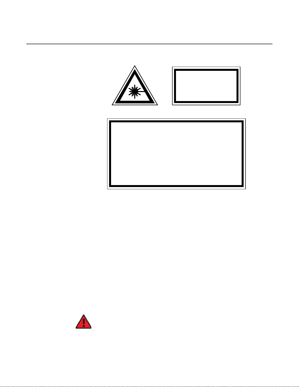
2.5.1.1 Laser warning labels
The following figures show the labels related to laser product, classification and
warning.
Figure 2 shows a laser product label.
Figure 2 Laser product label
Figure 3 shows a laser classification label. Laser classification labels may be
provided in other languages.
22
Edition 01 Issue: 01
Page 23

7368 ISAM ONT G-240W-C Product Guide ETSI ONT safety guidelines
LASER CLASSE 1CLASE 1 DEL LASER
CLASS 1 LASER PRODUCT PRODUCTO LASER CLASE 1
18992
'
'
R05.05.01 | December 2016 | 3FE 46690 AAAA TCZZA | Edition 01
Figure 3 Laser classification label
Figure 4 shows a laser warning label and an explanatory label for laser products.
Labels and warning may be provided in other languages. The explanatory label
provides the following information:
• a warning that calls attention to the invisible laser radiation
• an instruction against staring into the beam or viewing directly with optical
instruments
• wavelength
• normal output power
• maximum output power
Issue: 01 Edition 01 23
Page 24
ETSI ONT safety guidelines
INVISIBLE LASER RADIATION
DO NOT STARE INTO BEAM
OR VIEW DIRECTLY WITH
OPTICAL INSTRUMENTS
Wavelength(s): xxxx nm
Normal output power: xx m W
Max output power: yyy m W
Laser Warning Label
Laser Warning Label
CLASS 1 LASER PRODUCT
INVISIBLE LASER RADIATION PRESENT AT FIBER OPTIC CABLE
WHEN NOT CONNECTED. AVOID DIRECT EXPOSURE TO BEAM.
RAYONNEMENT LASER CLASSE 1
RAYONNEMENT LASER INVISIBLE
EVITER TOUTE EXPOSITION AU FAISCEAU
NE PAS DEMONTER. FAIRE APPEL A UN PERSONNELL QUALIFIE
CLASE 1 DEL LASER
RADIACION DE LASER INVISIBLE. EVITAR CUALOUIER EXPOSICION AL
RAYO LASER. NO DESMONTAR. LLAMAR A PERSONAL AUTORIZADO
Laser Warning Label
18993
'
R05.05.01 | December 2016 | 3FE 46690 AAAA TCZZA | Edition 01
Figure 4 Laser warning labels
7368 ISAM ONT G-240W-C Product Guide
2.5.2 Transmit optical output
The maximum transmit optical output of an ONT is +5 dBm.
2.5.3 Normal laser operation
24
In normal operation, fiber cable laser radiation is always off until it receives signal
from the line terminal card.
Eyes can be damaged when they exposed to a laser beam. Operating personnel
must observe the instructions on the laser explanatory label before plugging in the
optical module.
Danger — Risk of eye damage by laser radiation.
Edition 01 Issue: 01
Page 25

7368 ISAM ONT G-240W-C Product Guide ETSI ONT safety guidelines
R05.05.01 | December 2016 | 3FE 46690 AAAA TCZZA | Edition 01
2.5.4 Location class
Use cable supports and guides to protect the receptacles from strain.
2.6 Environmental requirements
See the ONT technical specification documentation for more information about
temperature ranges.
During operation in the supported temperature range, condensation inside the ONT
caused by humidity is not an issue. To avoid condensation caused by rapid changes
in temperature and humidity, Nokia recommends:
• The door of the ONT not be opened until temperature inside and outside the
enclosure has stabilized.
• If the door of the ONT must be opened after a rapid change in temperature or
humidity, use a dry cloth to wipe down the metal interior to prevent the risk of
condensation.
• When high humidity is present, installation of a cover or tent over the ONT helps
prevent condensation when the door is opened.
Issue: 01 Edition 01 25
Page 26

ETSI ONT safety guidelines
R05.05.01 | December 2016 | 3FE 46690 AAAA TCZZA | Edition 01
7368 ISAM ONT G-240W-C Product Guide
26
Edition 01 Issue: 01
Page 27

7368 ISAM ONT G-240W-C Product Guide ETSI environmental and CRoHS guidelines
R05.05.01 | December 2016 | 3FE 46690 AAAA TCZZA | Edition 01
3 ETSI environmental and CRoHS
guidelines
This chapter provides information about the ETSI environmental China Restriction of
Hazardous Substances (CRoHS) regulations that govern the installation and
operation of the optical line termination (OLT) and optical network termination (ONT)
systems. This chapter also includes environmental operation parameters of general
interest.
3.1 Environmental labels
This section describes the environmental instructions that are provided with the
customer documentation, equipment, and location where the equipment resides.
3.1.1 Overview
CRoHS is applicable to Electronic Information Products (EIP) manufactured or sold
and imported in the territory of the mainland of the People’s Republic of China. EIP
refers to products and their accessories manufactured by using electronic
information technology, including electronic communications products and such
subcomponents as batteries and cables.
3.1.2 Environmental related labels
Environmental labels are located on appropriate equipment. The following are
sample labels.
3.1.2.1 Products below Maximum Concentration Value (MCV) label
Figure 5 shows the label that indicates a product is below the maximum
concentration value, as defined by standard SJ/T11363-2006 (Requirements for
Concentration Limits for Certain Hazardous Substances in Electronic Information
Products). Products with this label are recyclable. The label may be found in this
documentation or on the product.
Issue: 01 Edition 01 27
Page 28

ETSI environmental and CRoHS guidelines
18986
R05.05.01 | December 2016 | 3FE 46690 AAAA TCZZA | Edition 01
Figure 5 Products below MCV value label
7368 ISAM ONT G-240W-C Product Guide
3.1.2.2 Products containing hazardous substances above Maximum Concentration Value (MCV) label
Figure 6 shows the label that indicates a product is above the maximum
concentration value, as defined by standard SJ/T11363-2006 (Requirements for
Concentration Limits for Certain Hazardous Substances in Electronic Information
Products). The number contained inside the label indicates the Environment-Friendly
User Period (EFUP) value. The label may be found in this documentation or on the
product.
Figure 6 Products above MCV value label
28
Edition 01 Issue: 01
Page 29

7368 ISAM ONT G-240W-C Product Guide ETSI environmental and CRoHS guidelines
R05.05.01 | December 2016 | 3FE 46690 AAAA TCZZA | Edition 01
Together with major international telecommunications equipment companies, Nokia
has determined it is appropriate to use an EFUP of 50 years for network
infrastructure equipment and an EFUP of 20 years for handsets and accessories.
These values are based on manufacturers' extensive practical experience of the
design, manufacturing, maintenance, usage conditions, operating environments,
and physical condition of infrastructure and handsets after years of service. The
values reflect minimum values and refer to products operated according to the
intended use conditions. See “Hazardous Substances Table (HST)” for more
information.
3.2 Hazardous Substances Table (HST)
This section describes the compliance of the OLT and ONT equipment to the CRoHS
standard when the product and subassemblies contain hazardous substances
beyond the MCV value. This information is found in this user documentation where
part numbers for the product and subassemblies are listed. It may be referenced in
other OLT and ONT documentation.
In accordance with the People’s Republic of China Electronic Industry Standard
Marking for the Control of Pollution Caused by Electronic Information Products
(SJ/T11364-2006), customers may access the Nokia Hazardous Substance Table,
in Chinese, from the following location:
• http://www.alcatel-sbell.com.cn/wwwroot/images/upload/private/1/media/ChinaRo
HS.pdf
3.3 Other environmental requirements
Observe the following environmental requirements when handling the P-OLT or ONT
equipment.
3.3.1 ONT environmental requirements
See the ONT technical specification documentation for more information about
temperature ranges.
3.3.2 Storage
According to ETS 300-019-1-1 - Class 1.1, storage of OLT equipment must be in
Class 1.1, weather-protected, temperature-controlled locations.
Issue: 01 Edition 01 29
Page 30

ETSI environmental and CRoHS guidelines
R05.05.01 | December 2016 | 3FE 46690 AAAA TCZZA | Edition 01
3.3.3 Transportation
According to EN 300-019-1-2 - Class 2.3, transportation of the OLT equipment must
be in packed, public transportation with no rain on packing allowed.
3.3.4 Stationary use
According to EN 300-019-1-3 - Class 3.1/3.2/3.E, stationary use of OLT equipment
must be in a temperature-controlled location, with no rain allowed, and with no
condensation allowed.
3.3.5 Thermal limitations
When the OLT is installed in the CO or CEV, install air filters on the P-OLT. The
thermal limitations for OLT operation in a CO or CEV are:
7368 ISAM ONT G-240W-C Product Guide
• operating temperature: 5°C to 40°C (41°F to 104°F)
• short-term temperature: –5°C to 50°C (23°F to 122°F)
• operating relative humidity: 5% to 85%
• short-term relative humidity: 5% to 95%, but not to exceed 0.024 kg of water/kg
3.3.6 Material content compliance
European Union (EU) Directive 2002/95/EC, “Restriction of the use of certain
Hazardous Substances” (RoHS), restricts the use of lead, mercury, cadmium,
hexavalent chromium, and certain flame retardants in electrical and electronic
equipment. This Directive applies to electrical and electronic products placed on the
EU market after 1 July 2006, with various exemptions, including an exemption for
lead solder in network infrastructure equipment. Nokia products shipped to the EU
after 1 July 2006 comply with the EU RoHS Directive.
Nokia has implemented a material/substance content management process. The
process is described in: Nokia process for ensuring RoHS Compliance
(1AA002660031ASZZA). This ensures compliance with the European Union
Directive 2011/65/EU on the Restriction of the Use of Certain Hazardous Substances
in Electrical and Electronic Equipment (RoHS2). With the process equipment is
assessed in accordance with the Harmonised Standard EN50581:2012 (CENELEC)
on Technical documentation for the assessment of electrical and electronic products
with respect to the restriction of hazardous substances.
30
Edition 01 Issue: 01
Page 31

7368 ISAM ONT G-240W-C Product Guide ETSI environmental and CRoHS guidelines
R05.05.01 | December 2016 | 3FE 46690 AAAA TCZZA | Edition 01
3.3.7 End-of-life collection and treatment
Electronic products bearing or referencing the symbol shown in Figure 7, when put
on the market within the European Union (EU), shall be collected and treated at the
end of their useful life, in compliance with applicable EU and local legislation. They
shall not be disposed of as part of unsorted municipal waste. Due to materials that
may be contained in the product, such as heavy metals or batteries, the environment
and human health may be negatively impacted as a result of inappropriate disposal.
Note — In the European Union, a solid bar under the symbol for
a crossed-out wheeled bin indicates that the product was put on
the market after 13 August 2005.
Figure 7 Recycling/take back/disposal of product symbol
At the end of their life, the OLT and ONT products are subject to the applicable local
legislations that implement the European Directive 2012/19EU on waste electrical
and electronic equipment (WEEE).
There can be different requirements for collection and treatment in different member
states of the European Union.
In compliance with legal requirements and contractual agreements, where
applicable, Nokia will offer to provide for the collection and treatment of Nokia
products bearing the logo shown in Figure 7 at the end of their useful life, or products
displaced by Nokia equipment offers. For information regarding take-back of
equipment by Nokia, or for more information regarding the requirements for
recycling/disposal of product, contact your Nokia account manager or Nokia take
back support at sustainability.global@nokia.com.
Issue: 01 Edition 01 31
Page 32

ETSI environmental and CRoHS guidelines
R05.05.01 | December 2016 | 3FE 46690 AAAA TCZZA | Edition 01
7368 ISAM ONT G-240W-C Product Guide
32
Edition 01 Issue: 01
Page 33

7368 ISAM ONT G-240W-C Product Guide G-240W-C unit data sheet
R05.05.01 | December 2016 | 3FE 46690 AAAA TCZZA | Edition 01
4 G-240W-C unit data sheet
4.1 G-240W-C part numbers and identification
4.2 G-240W-C general description
4.3 G-240W-C software and installation feature support
4.4 G-240W-C interfaces and interface capacity
4.5 G-240W-C LEDs
4.6 G-240W-C detailed specifications
4.7 G-240W-C GEM ports and T-CONTs
4.8 G-240W-C performance monitoring statistics
4.9 G-240W-C functional blocks
4.10 G-240W-C standards compliance
4.11 G-240W-C special considerations
4.1 G-240W-C part numbers and identification
Table 2 provides part numbers and identification information for the G-240W-C
indoor ONT.
Table 2 Identification of G-240W-C indoor ONTs
Ordering kit
part number
3FE 46252 AA 3FE 46256 AA Package P 2 POTS ports, 4 10/100/1000 Base-T Ethernet
3FE 46252 AB
Customer-specific
Provisioning
number
3FE 46256 AB Package P 2 POTS ports, 4 10/100/1000 Base-T Ethernet
Description CLEI CPR ECI/
interfaces, and 802.11b/g/n/ac Wi-Fi radio with on/off switch.
This ONT also has 2 USB 2.0 ports.
Includes 2-pin wall-mounted US AC/DC adapter.
interfaces, and 802.11b/g/n/ac Wi-Fi radio with on/off switch.
Maximum reach power of the antenna: 250mw; antenna not
included.
This ONT also has 2 USB 2.0 ports.
Includes 2-pin wall-mounted US AC/DC adapter.
Bar
code
———
———
(1 of 2)
Issue: 01 Edition 01 33
Page 34

G-240W-C unit data sheet
R05.05.01 | December 2016 | 3FE 46690 AAAA TCZZA | Edition 01
7368 ISAM ONT G-240W-C Product Guide
Ordering kit
part number
3FE 46252 BA 3FE 46256 AA Package P 2 POTS ports, 4 10/100/1000 Base-T Ethernet
3FE 46252 BB
Customer-specific
3FE 46252 CA 3FE 46256 AA Package P 2 POTS ports, 4 10/100/1000 Base-T Ethernet
3FE 46252 DA 3FE 46256 AA Package P 2 POTS ports, 4 10/100/1000 Base-T Ethernet
(2 of 2)
Provisioning
number
3FE 46256 BB Package P 2 POTS ports, 4 10/100/1000 Base-T Ethernet
Description CLEI CPR ECI/
interfaces, and 802.11b/g/n/ac Wi-Fi radio with on/off switch.
This ONT also has 2 USB 2.0 ports.
Includes 3-pin wall-mounted European (EU) AC/DC adapter.
interfaces, and 802.11b/g/n/ac Wi-Fi radio with on/off switch.
This ONT also has 2 USB 2.0 ports.
Includes 3-pin wall-mounted European (EU) AC/DC adapter.
interfaces, and 802.11b/g/n/ac Wi-Fi radio with on/off switch.
This ONT also has 2 USB 2.0 ports.
Includes 3-pin wall-mounted British (UK) AC/DC adapter.
interfaces, and 802.11b/g/n/ac Wi-Fi radio with on/off switch.
This ONT also has 2 USB 2.0 ports.
Includes 2-pin wall-mounted Japanese AC/DC adapter.
PSE/METI tracking certified
Table 3 provides the power supply information for the G-240W-C ONT. For more
information on power supplies, see the 7368 ISAM ONT Power Supply and UPS
Guide.
Bar
code
———
———
———
———
Table 3 G-240W-C power supply
ONT part numbers Power model Power
Kit: 3FE 46252 BA
EMA: 3FE 256 AA
Kit: 3FE 46252 CA
EMA: 3FE 256 AA
Kit: 3FE 46252 AB
EMA: 3FE 256 AB
Mass Power
NBS40C120300VE
SOY Technology
SOY-1200300EU
Mass Power
NSB40C120300UK
SOY Technology
SOY-1200300GB
SOY Technology
SUN-1200300US
information
36 Watt AC/DC
power adapter
36 Watt AC/DC
power adapter
36 Watt AC/DC
power adapter
36 Watt AC/DC
power adapter
36 Watt AC/DC
power adapter
Customer category or
country compliance
tested for
Europe, CE certified 2-pin EU
Europe, CE certified 2-pin EU
UK, CE certified 3-pin UK
UK, CE certified 3pin UK
ANSI municipality US,
Canada
UL/CUL certified, UL
60950
Notes
input plug
input plug
input plug
input plug
2-pin US
input plug
with LED
34
Edition 01 Issue: 01
Page 35

7368 ISAM ONT G-240W-C Product Guide G-240W-C unit data sheet
R05.05.01 | December 2016 | 3FE 46690 AAAA TCZZA | Edition 01
4.2 G-240W-C general description
G-240W-C indoor ONTs provide the subscriber interface for the network by
terminating the PON interface and converting it to user interfaces that directly
connect to subscriber devices. The ONT is compatible with all existing subscriber
equipment, including analog phones with both tone and rotary dial capabilities,
cordless phones, modems, fax machines, and caller ID boxes (Type I, Type II, and
Type III).
G-240W-C indoor ONTs provide the following functions:
• Single fiber GPON interface with 1.244Gbit/s upstream and 2.488Gbit/s
downstream data rates
• Advanced data features such as VLAN tag manipulation, classification, and
filtering.
• Traffic classification and QoS capability
• Analog Telephone Adapter (ATA) function integrated based on SIP (RFC3261)
and H.248, with various CLASS services supported, including Caller ID, Call
Waiting, Call Forwarding, and Call Transfer
• 5 REN per line
• Multiple voice Codec
• MDI/MDIX auto-negotiation
• Line Rate L2 traffic
• Internal Switch
• UPnP IGD1.0 support
• Bridged mode or routed mode per LAN port
• Optics that support received signal strength indication (RSSI)
• Internal DHCP server, with configurable DHCP pool and gateway
• WPS on wireless authorization support
• 802.11ac support
• 2.4GHz/5GHz dual band concurrency, both with configurable Wi-Fi tx power from
100mw to 500mw, in 100mw increments.
• Enhanced ONT; SSH-Telnet-FTP and http server are disabled from the W AN side
• Concurrent 802.11n 2x2 MIMO in 2.4GHz and 802.11ac 4x4 MIMO in 5GHz
• 64/128 WEP encryption
• WPA, WPA-PSK/TKIP
• WPA2, WPA2-PSK/AES
• support for multiple SSIDs (private and public instances); contact your Nokia
representative for further details.
• WLAN on/off push button
• WPS/PBC buttons (for 2.4G and 5G)
• Ethernet-based Point-to-Point (PPPoE)
• Network Address Translation (NAT)
• Network Address Port Translation (NAPT)
Issue: 01 Edition 01 35
Page 36

G-240W-C unit data sheet
R05.05.01 | December 2016 | 3FE 46690 AAAA TCZZA | Edition 01
ALG and UPnP port forwarding
•
• DMZ
• IP/MAC filter
• Multi-level firewall
• DNS server
• DHCP client/server
• support HT20/HT40 for 802.11b/g/n, and HT20/40/80 for 802.11AC
• support for up to 32 simultaneous wireless connections
• External USB HD (Hard Drive) support, accessible to all LAN devices
• support for AIS with DOWN MEP
4.2.1 Configuring the G-240W-C to function as a single port ONT
In addition to functioning as a residential gateway, the G-240W-C ONT can be
configured to function as a single port ONT.
7368 ISAM ONT G-240W-C Product Guide
In the custom configuration, the ONT reports to the OLT as one PPTP port. The
physical Ethernet port of the ONT is managed by the RGW using the TR-069
protocol, rather than by the ONT/OMCI.
To enable the ONT to function as a single port ONT, the value of the parameter:
InternetGatewayDevice.DeviceInfo.X_ALU-COM_PortReport2OLT.PPTP
must be set to
PPTP_one
A custom pre-configuration file is required to operate the G-240W-C as a single-port
ONT. Contact your Nokia support engineer to arrange for a custom pre-configuration
file.
4.2.2 TR-069 support
The ONT supports the reading of optical parameters via TR-069:
• laser bias current
• voltage
• temperature
• received signal levels
• lower thresholds
36
These are the same optical parameters supported in the GUI. For more information,
see Table 21 in the chapter “Configure a G-240W-C indoor ONT”.
Edition 01 Issue: 01
Page 37

7368 ISAM ONT G-240W-C Product Guide G-240W-C unit data sheet
R05.05.01 | December 2016 | 3FE 46690 AAAA TCZZA | Edition 01
The ONT supports the status retrieval and configuration of the following Wi-Fi
parameters via TR-069:
• channel
• SSID
• password for WPA and WEP
• Tx power (transmission rate in percentage of maximum transmit power)
These are the same TR-069 object parameters that are supported in the GUI. For
more information, see Tables 17, 28, and 29 in the chapter “Configure a G-240W-C
indoor ONT”.
The ONT also supports TR-069 statistics for LAN, WAN, and WiFi.
4.2.3 TR-104 parameter extension support for voice service
A proprietary attribute has been added to the TR-104 Voice Service object structure
to enable the ACS to configure the name of the embedded GSIP XML file to be
selected.
The TR-104 Voice Service Object is:
InternetGatewayDevice.Services.VoiceService.{i}.Capabilities.SIP.
The proprietary attribute is: X_ALU-COM_XML_File_Name_Path.
4.2.4 TR-104 voice-related alarms
The G-240W-C ONT supports the following four TR-104 voice-related alarms on a
per FXS port basis.
These alarms all represent SIP registration failures with an alarm level of MAJOR.
• SIPREGDNS: domain name could not be resolved
• SIPREGAUTH: authentication failed
• SIPREGTO: re-transmissions timed out
• SIPREGERR: error response from the registration server
4.2.5 TR-181 Wi-Fi objects adapted in TR-098
TR-181 is the device data model for TR-069 Wi-Fi objects.
Issue: 01 Edition 01 37
Page 38

G-240W-C unit data sheet
R05.05.01 | December 2016 | 3FE 46690 AAAA TCZZA | Edition 01
The following TR-181 Wi-Fi objects (and sub-objects) adapted in TR-098 are
supported in this release:
• Device.WiFi
• Device.WiFi.Radio.{i}.
• Device.WiFi.Radio.{i}.Stats.
• Device.WiFi.SSID.{i}.
• Device.WiFi.SSID.{i}.Stats.
• Device.WiFi.AccessPoint.{i}.
• Device.WiFi.AccessPoint.{i}.Security.
• Device.WiFi.AccessPoint.{i}.WPS.
• Device.WiFi.AccessPoint.{i}.AssociatedDevice{i}.
• Device.WiFi.Endpoint.{i}.
• Device.WiFi.Endpoint.{i}.Stats.
• Device.WiFi.Endpoint.{i}.Security.
• Device.WiFi.Endpoint.{i}.Profile{i}.
• Device.WiFi.Endpoint.{i}.Profile{i}.Security.
• Device.WiFi.Endpoint.{i}.WPS.
• Device.WiFi.NeighboringWiFiDiagnostics.
• Device.WiFi.NeighboringWiFiDiagnostics.Result.{i}.
7368 ISAM ONT G-240W-C Product Guide
4.2.6 Mobile offload support
As part of the E2E solution supported by the ISAM 7750 service router, the
G-240W-C ONT offers Mobile Offload support using a combination of EAP-SIM and
ITU-T 802.11.
EAP-SIM is an authentication method that uses the user credentials on the SIM card
and EAP to authenticate the user with the Wi-Fi network, removing the need for user
input (username and password).
A dedicated public mobile offload SSID in the ONT enables mobile subscribers to
connect to the Internet. Encryption is supported by 802.11, providing seamless Wi-Fi
authentication for SIM-based user equipment.
The ONT acts as the RADIUS client and sends the encapsulated EAP messages to
the AAA server via the WLAN Gateway, which acts as the RADIUS proxy server. The
interaction between the ONT and the AAA server provides subscriber management
for authenticated mobile users without adding authentication load to the 3G network.
38
Edition 01 Issue: 01
Page 39

7368 ISAM ONT G-240W-C Product Guide G-240W-C unit data sheet
R05.05.01 | December 2016 | 3FE 46690 AAAA TCZZA | Edition 01
4.2.7 Bridged Residential Gateway (BRG) support
The BRG receives IP addresses for the WAN interface using DHCP or PPPoE. The
BRG can use either Ipv4 or Ipv6 addresses. BRG uses OpenFlow protocol version
1.3.1 to manage Access Control List entries and routing protocols. TR-069 can be
used to manage the local DHCP server and the soft GRE tunnel.
The BRG supports the encapsulation of Ethernet frames from different bridges in the
GRE tunnel to the access tunnel. Multiple bridges can map to the same GRE tunnel.
Where encapsulated packets exceed the MTU (packet size), fragmentation is also
supported.
Upstream QoS can reserve bandwidth for public and private Wi-Fi bridges, based on
profiles defined for the access uplink speed. A unique VLAN tag can be configured
for each SSID on the BRG. Unicast QoS adjustment can be enabled to support
Multicast IPTV
Liveness detection and redundancy, link failure notification, and DHCP local server
fallback are provided to help manage potential problems with gateway access. Event
notification via TR-069 reports when the PON link is up and the tunnel is
unreachable.
4.2.8 Support for soft GRE tunnels
This section describes the support for soft GRE tunnels for integration with the 7750
Service Router WLAN gateway. The Nokia 7750 Service Router WLAN GW can
accept soft GRE tunnels from any IP Source Address, in a preconfigured Subnet or
Access Control List, or MPLS label.
4.2.8.1 GRE
Generic Routing Encapsulation (GRE) is a tunneling protocol that can encapsulate a
wide variety of network layer protocols inside virtual point-to-point links over an
Internet Protocol network. GRE provides a secure path for transporting packets
through a public network. In essence, GRE creates a private P2P connection, similar
to a VPN, between clients and servers. GRE is the preferred transport mechanism
between the Carrier Wi-Fi access network and the WLAN GW.
GRE works by encapsulating a payload (an inner packet that needs to be delivered
to a destination network) inside an outer IP packet. GRE tunnel endpoints send
payloads through GRE tunnels by routing encapsulated packets through intervening
IP networks. The inner packets are not parsed along the way; only the outer IP
packets are parsed as they are forwarded towards the GRE tunnel en dpoint, where
the GRE encapsulation is removed, and the payload is forwarded to its final
destination.
Issue: 01 Edition 01 39
Page 40

G-240W-C unit data sheet
DHCP
server
Motive
Access Network
Security
Diag.
Qos
Viurs
scanner
Parental
Cntl
BW on
Demand
Basic
vCPE
VSR
Home
Network
VLAN: 100
Soft-GRE
Tunnel
TR-069 VLAN: 881
IPTV VLAN: 981
Mgmt
IPTV
Network
BRG
25265
R05.05.01 | December 2016 | 3FE 46690 AAAA TCZZA | Edition 01
4.2.8.2 Soft GRE
In soft GRE, only one side of the tunnel needs to be configured; the other end learns
the remote IP addresses of all remote tunnel endpoints by examining the incoming
GRE packets.
GRE tunnels can be automatically created when devices attach to the AP,
eliminating the need for each AP to be explicitly provisioned on the WLAN Gateway.
Because this soft GRE is stateless and the tunnel contexts are created based on
need, the WLAN Gateway does not need to maintain states for unused tunnels,
which improves scalability.
The operator can restrict the traffic going through the GRE tunnel based on the
SSIDs or LAN ports.
Figure 8 illustrates the soft GRE architecture.
Figure 8 SoftGRE-based architecture
7368 ISAM ONT G-240W-C Product Guide
40
For more information about soft GRE architecture and configuration procedures, see
the 7368 Configuration, Management, and Troubleshooting guide, which contains
the vCPE User Guide.
Note — While the vCPE forwards all traffic over the GRE
tunnel, the soft GRE architecture for the G-240W-C enables the
operator to restrict the traffic over the GRE tunnel bases on
SSIDs or LAN ports.
Edition 01 Issue: 01
Page 41

7368 ISAM ONT G-240W-C Product Guide G-240W-C unit data sheet
R05.05.01 | December 2016 | 3FE 46690 AAAA TCZZA | Edition 01
4.3 G-240W-C software and installation feature support
For information on installing or replacing the G-240W-C see:
• Install a G-240W-C indoor ONT
• Replace a G-240W-C indoor ONT
For information on the following topics, see the 7368 ISAM ONT Product Overview
Guide:
• ONT and MDU general descriptions of features and functions
• Ethernet interface specifications
• POTS interface specifications
• RSSI specifications
• Wi-Fi specifications
• ONT optical budget
• SLID entry via Ethernet port
• ONT management using an ONT interface
4.4 G-240W-C interfaces and interface capacity
Table 4 describes the supported interfaces and interface capacity for G-240W-C
indoor ONTs.
Table 4 G-240W-C indoor ONT interface connection capacity
ONT type
and model
G-240W-C
(1)
Note
(1)
The G-240W-C ONTs provide Wi-Fi service that is enabled and disabled using a Wi-Fi on/off switch.
Maximum capacity
POTS 10/ 100
BASE-T
2— 4 — — ——— 1
10/ 100/ 1000
BASE-T
RF video
(CATV)
MoCA VDSL2 E1/T1 Local craft GPON
4.4.1 G-240W-C connections and components
Figure 9 shows the physical connections for G-240W-C indoor ONTs,
SC/APC
Issue: 01 Edition 01 41
Page 42

G-240W-C unit data sheet
ON/OFFPOWER
USB2USB1LAN4LAN3LAN2LAN1
TEL1 TEL2
WLAN
RESET
WPS2.4G
WPS5G
Wall
mounting
hole
Wall
mounting
hole
POTS
ports (2)
(RJ-11)
Ethernet
ports (4)
(RJ-45)
USB
ports (2)
Wi-Fi
security
buttons
2.4G and 5G
Reset
button
Powe r
input
Fiber optic
port
Wireless
on/off
button
On/off
button
25272
25273
ON/OFFPOWER
USB2USB1LAN4LAN3LAN2LAN1
TEL1 TEL2
WLAN
RESET
WPS2.4G
WPS5G
Fiber optic connector
(without cover)
R05.05.01 | December 2016 | 3FE 46690 AAAA TCZZA | Edition 01
7368 ISAM ONT G-240W-C Product Guide
Figure 9 G-240W-C indoor ONT physical connections
Figure 10 shows the G-240W-C ONT without the fiber cover
Figure 10 G-240W-C ONT without fiber cover
Figure 11 shows the G-240W-C ONT with the fiber cover
42
Edition 01 Issue: 01
Page 43

7368 ISAM ONT G-240W-C Product Guide G-240W-C unit data sheet
25274
ON/OFFPOWER
USB2USB1LAN4LAN3LAN2LAN1
TEL1 TEL2
WLAN
RESET
WPS2.4G
WPS5G
Fiber optic connector
(covered)
R05.05.01 | December 2016 | 3FE 46690 AAAA TCZZA | Edition 01
Figure 11 G-240W-C ONT with fiber cover
Table 5 describes the physical connections for G-240W-C indoor ONTs.
Table 5 G-240W-C indoor ONT physical connections
Connection
POTS ports This connection is provided through RJ-11 ports. Up to two POTS connections are
Ethernet ports This connection is provided through Ethernet RJ-45 connectors. Up to four 10/100/1000
USB ports This connection is provided through 2 USB ports. The ONT supports external USB hard
WPS buttons The Wi-Fi Protected Setup buttons are labeled WPS2.4G and WPS5G. These buttons
WLAN button Wi-Fi service is compliant with IEEE 802.11 standards and is enabled and disabled using
Reset button Pressing the Reset button for less than 10 seconds reboots the ONT; pressing the Reset
Power input This connection is provided through the power connector. A power cable fitted with a barrel
On/Off button This button turns the ONT on or off.
Fiber optic port This port provides the connection for the fiber optic cable.
(1)
Description
supported.The POTS ports support voice services.
Base-T Ethernet interfaces are supported.The Ethernet ports can support both data and
in-band video services on all four interfaces.
drives that can be made accessible to all LAN devices.
enable and disable WLAN data encryption.
the WLAN button.
button for 10 seconds resets the ONT to the factory defaults, except for the LOID and SLID.
connector is used to make the connection.
Note
(1)
The primary path for the earth ground for these ONTs is provided by the 12V Return signal in the power
connector.
Issue: 01 Edition 01 43
Page 44

G-240W-C unit data sheet
TEL
1 and 2
VoI P
WPS
2.4G
WLAN
2.4G
Lan
1 to 4
Auth
Link
Powe r
25277
POWER
LINK
AUTH
LAN1
LAN2
LAN3
LAN4
TEL1
T
EL2
VOIP
W
P
S
2.4G
W
PS 5G
WLAN 2.4G
WLA
N
5G
USB
INTE
R
NET
USB
WPS5GWLAN
5G Internet
R05.05.01 | December 2016 | 3FE 46690 AAAA TCZZA | Edition 01
4.5 G-240W-C LEDs
Figure 12 shows the G-240W-C indoor ONT LEDs.
Figure 12 G-240W-C indoor ONT LEDs
7368 ISAM ONT G-240W-C Product Guide
Table 6 provides LED descriptions for G-240W-C indoor ONTs.
Table 6 G-240W-C indoor ONT LEDs
Indicator LED color and
behavior
Power Green solid
Red solid
Off
Link Green solid
Off
Auth Green solid
Green flashing
Off
LAN 1 to 4 Green solid
Green flashing
Off
TEL 1 to 2 Green solid
Green flashing
Off
VOIP Green solid
Off
(1 of 2)
LED behavior description
Power on
Light failed on startup (for example corrupt flash), or self test failed on startup, or self test failed
during regular operation or when executed over OMCI
Power off
GPON link between ONT and OLT is operating normally
GPON link is down or no link connected
ONT is authorized
ONT is process of ranging or synchronizing on OMCI
ONT is not authorized
Ethernet is linked
LAN activity is present (in either direction)
ONT power is off or Ethernet is not connected
Phone is off hook
Phone is in ‘call in’ or ‘talking’ condition
All phones are on hook
VOIP service is built up and can provide service
VOIP service is not built up or out of service
44
Edition 01 Issue: 01
Page 45

7368 ISAM ONT G-240W-C Product Guide G-240W-C unit data sheet
R05.05.01 | December 2016 | 3FE 46690 AAAA TCZZA | Edition 01
Indicator LED color and
WPS
2.4G and 5G
WLAN
2.4G and 5G
USB Green solid
INTERNET Green solid
(2 of 2)
behavior
Green solid
Green flashing
Red solid
Off
Off
Green solid
Green flashing
Green flashing
Off
Green flashing
Off
4.6 G-240W-C detailed specifications
LED behavior description
WiFi protected setup link is up (negotiation and auto-configuration successful)
WiFi protected setup link activity (negotiation and auto-configuration ongoing)
WiFi protected setup processing exception or multiple peers using WPS simultaneously
WiFi protected setup link down or no link connected (negotiation has not started or has failed)
WLAN link is disabled
WLAN link is enabled
Traffic is passing via WLAN link
At least one USB device is connected
There is traffic activity on at least on USB device
No USB device is connected
HSI WAN is connected: a) the device has an IP address assigned from IPCP, DHCP, or static,
and no traffic has been detected; b) the session is dropped due to idle timeout but the PON
link is still present.
PPPoE or DHCP connection in progress
HSI WAN is not connected: a) there is no physical interface connection; b) the device is in
bridged mode without an assigned IP address; c) the session has been dropped for reasons
other than idle timeout.
Table 7 lists the physical specifications for G-240W-C indoor ONTs.
Table 7 G-240W-C indoor ONT physical specifications
Description Specification
Length 11.0 in. (280 mm)
Width 6.7 in. (170 mm)
Height 1.6 in. (40 mm)
Weight [within ± 0.5 lb (0.23 kg)]
(net weight of ONT)
1.42 lb (0.644 kg)
Table 8 lists the power consumption specifications for G-240W-C indoor ONT.
Issue: 01 Edition 01 45
Page 46

G-240W-C unit data sheet
R05.05.01 | December 2016 | 3FE 46690 AAAA TCZZA | Edition 01
Table 8 G-240W-C indoor ONT power consumption specifications
7368 ISAM ONT G-240W-C Product Guide
Mnemonic Maximum
power (Not to
exceed)
G-240W-C 30 W 2 POTS off-hook, 4
Condition Minimum
power
12 W 2 POTS on-hook, other
10/100/1000 Base-T
Ethernet, Wi-Fi operational
Table 9 lists the environmental specifications for G-240W-C indoor ONT.
Table 9 G-240W-C indoor ONT environmental specifications
Mounting
method
On desk or wall
mounted
Temperature range and humidity Altitude
Operating: 23°F to 113°F (-5°C to 45°C)
ambient temperature
10% to 90% relative humidity,
non-condensing
Storage: -4°F to 158°F (-20°C to 70C)
Contact your Nokia technical support
representative for more information
4.7 G-240W-C GEM ports and T-CONTs
Condition
interfaces/services not
provisioned
Table 10 lists the maximum number of supporte d T-CONTs and GEM ports. See the
appropriate release Customer Release Notes for the most accurate list of supported
devices.
Table 10 G-240W-C indoor ONT capacity for GEM ports and T-CONTs
ONT or MDU Maximum Notes
Package P ONTs
GEM ports per indoor or outdoor ONT 124 124 are present; 122 are available, and 2 are
T-CONTs per indoor or outdoor ONT 32 32 are present; 31 are available, and 1 is
reserved for multicast and debugging
reserved for OMCI
46
Edition 01 Issue: 01
Page 47

7368 ISAM ONT G-240W-C Product Guide G-240W-C unit data sheet
R05.05.01 | December 2016 | 3FE 46690 AAAA TCZZA | Edition 01
4.8 G-240W-C performance monitoring statistics
The following section identifies the supported performance monitoring statistics for
G-240W-C ONTs. A check mark indicates the statistic is supported on that ONT. An
empty cell indicates the statistic is not supported. The following tables are
categorized by supported alarm types:
• Table 11 provides statistics for ONTENET type counters
• Table 12 provides statistics for ONTL2UNI type counters
• Table 13 provides statistics for PONONTTC, PONONTMCTC, PONONTTCHSI,
PONONTTCCES, PONONTTCFLOW, and PONONTTCVOIP type counters
• Table 14 provides statistics for PONONTTC aggregate type counters
Note — If you have trouble accessing G-240W-C ONTs
performance monitoring statistics using TL1, please contact
your Nokia support representative for more information about
how to access and retrieve performance monitoring type
counters.
Table 11 Package P ONTs ONTENET performance monitoring statistics
ONT ONTENET statistics
LC
EC
FCSE
G-240W-C
Note
(1)
(1)
✓✓✓✓✓✓✓✓✓✓✓✓✓✓
A 5 second polling window limitation exists on the ONT, therefore the margin of error for each 15-min window
is 5 seconds
RBO
SCF
MCF
DT
IMTE
CSE
AE
FTL
TBO
IMRE
SQE
Table 12 Package P ONTs ONTL2UNI performance monitoring statistics
ONT ONTL2UNI statistics
BYTES
G-240W-C
(1)
FRAMES
✓✓✓✓✓✓✓✓✓✓✓
MCFRAMES
DSDRPDFRMS
USDRPDFRMS
USFRAMES
DSFRAMES
USBYTES
DSBYTES
USMCFRAMES
DSMCFRAMES
Issue: 01 Edition 01 47
Page 48

G-240W-C unit data sheet
R05.05.01 | December 2016 | 3FE 46690 AAAA TCZZA | Edition 01
Note
(1)
A 5 second polling window limitation exists on the ONT, therefore the margin of error for each 15-min window
is 5 seconds
Table 13 Package P ONTs PONONTTC, PONONTMCTC, PONONTTCHSI,
ONT PONONTTC, PONONTMCTC, PONONTTCHSI, PONONTTCCES,
7368 ISAM ONT G-240W-C Product Guide
PONONTTCCES, PONONTTCFLOW, PONONTTCVOIP performance monitoring statistics
PONONTTCFLOW, PONONTTCVOIP statistics
TXBLOCKS
G-240W-C
Note
(1)
(1)
A 5 second polling window limitation exists on the ONT, therefore the margin of error for each 15-min window
is 5 seconds
✓✓✓✓✓
TXFRAGS
RXBLOCKS
RXFRAGS
LOSTFRAGS
BADGEMHDRS
Table 14 Package P ONTs PONONTTC aggregate performance monitor-
ing statistics
ONT PONONTTC (aggregate) statistics
TXBLOCKS
G-240W-C
Note
(1)
(1)
A 5 second polling window limitation exists on the ONT, therefore the margin of error for each 15-min window
is 5 seconds
✓✓✓✓✓
TXFRAGS
RXBLOCKS
RXFRAGS
LOSTFRAGS
BADGEMHDRS
48
Edition 01 Issue: 01
Page 49

7368 ISAM ONT G-240W-C Product Guide G-240W-C unit data sheet
BOB
LED
USB
I2C/RX/TX_SD,TX_PD
2*USB 2.0
SerDes
LED_CLK/DAT
Shift
Register
RD/
Antenna
WIFI
11b/g/n
Tr ansformSLIC
4*RJ45
2x2
11b/g/n
Protection
RD/
Antenna
NAND
FLASH
SOC
WIFI
11ac
4x4
11ac
DDR3
I2C
EEPROM
PCI-E0
PCIE1
GE3GE2GE1GE0
2*RJ11
26004
R05.05.01 | December 2016 | 3FE 46690 AAAA TCZZA | Edition 01
4.9 G-240W-C functional blocks
G-240W-C indoor ONTs are single-residence ONTs that support Wireless (Wi-Fi)
service. Wi-Fi service on these ONTs is compliant with the IEEE 802.11 standard
and enabled or disabled using a WLAN button. In addition to the Wi-Fi service, these
ONTs transmit Ethernet packets to four RJ-45 Ethernet ports and voice traffic to two
RJ-11 POTS ports. These ONTs also feature fiber optic, USB, and power
connectors.
Figure 13 shows the functional blocks for G-240W-C indoor ONT.
Figure 13 Single-residence Wi-Fi ONT with Gigabit Ethernet and POTS and without RF video
ONT SoC technology serves as the main hardware block for these ONTs; see
Figure 14.
Issue: 01 Edition 01 49
Page 50

G-240W-C unit data sheet
Control
processor
Ethernet
MACs
Ethernet ports GPON
POTS ports
DSP
GPON
MAC
SoC
19421
SoC Bridge
R05.05.01 | December 2016 | 3FE 46690 AAAA TCZZA | Edition 01
Figure 14 G-240W-C ONT hardware block
7368 ISAM ONT G-240W-C Product Guide
ONT SoC technology consists of five key elements:
• GPON MAC
The Gigabit Passive Optical Network Media Access Control (GPON MAC)
element on the SoC terminates the GPON interface using an optical diplexer. This
interface supports GPON as described in G.984.3 (GPON TC Layer) ITU
specification.
• Ethernet MAC
The SoC provides up to four GE MACs.
• DSP interface
The Digital Signal Processor (DSP) provides voice processing for 2 POTS lines
with 3-way calling. The DSP has a dedicated 64 kbyte instruction cache and
shares a 32 kbyte data cache with the Control Processor. It provides up to 4
network processor cores, each at 800MHz.
• Control Processor
The Control Processor features an integral memory management unit that
supports a dedicated 64 kbyte instruction cache and shares a single 32 kbyte data
cache with the DSP. The Control Processor and DSP also include a single
channel Data Management Application (DMA) controller with a 4 kbyte read
ahead low-latency Dynamic Random Access Memory (DRAM) access port.
• Switch matrix
The Switch matrix provides an integrated data channel between the four GE
MACs, the GPON MAC, the DSP, the control processor, and the other integrated
elements such as flash memory, DRAM, and the local bus controller.
50
Edition 01 Issue: 01
Page 51

7368 ISAM ONT G-240W-C Product Guide G-240W-C unit data sheet
R05.05.01 | December 2016 | 3FE 46690 AAAA TCZZA | Edition 01
These ONTs can also interact with additional hardware components to support
functionality not provided by the SoC technology.
4.10 G-240W-C standards compliance
G-240W-C indoor ONTs are compliant with the following standards:
• 802.1p marking and VLAN based pbit is supported
• EN 300-328 v1.9.1 wide band data transmission standards for 2.4GHz bands
• G.711 support for FAX and modem connection
• G.984 support GPON interface (framing)
• G.984.2 support for Amd1, class B+
• G.984.3 support for activation and password functions
• G.984.3 support for AES with operator enable/disable on per port-ID level
• G.984.3 support for FEC in both upstream and downstream directions
• G.984.3 support for multicast using a single GEM Port-ID for all video traffic
• G984.4 and G.983.2 support for ONT management and provisioning
• CE marking for European standards for health, safety, and environmental
protection
4.10.1 Energy-related products standby and off modes compliance
Hereby, Nokia declares that the G-240W-C ONTs are in compliance with the
essential requirements and other relevant provisions of Directive 2009/125/EC
together with Commission Regulation (EC) No 1275/2008 and Commission
Regulation (EC) No 801/2013.
The G-240W-C ONTS qualify as equipment with high network availability (HiNA)
functionality. Since the main purpose of G-240W-C ONTs is to provide network
functionality with HiNA 7 days /24 hours, the modes Off/Standby, Power
Management, and Networked Standby are inappropriate.
For information about the type and number of network ports, see “G-240W-C
interfaces and interface capacity” in this chapter.
For information about power consumption, see “G-240W-C detailed specifications”
in this chapter.
Issue: 01 Edition 01 51
Page 52

G-240W-C unit data sheet
R05.05.01 | December 2016 | 3FE 46690 AAAA TCZZA | Edition 01
4.10.2 FCC statement
This equipment has been tested and found to comply with the limits for a Class B
digital device, pursuant to part 15 of the FCC Rules. These limits are designed to
provide reasonable protection against harmful interference in a residential
installation. This equipment generates, uses and can radiate radio frequency energy
and, if not installed and used in accordance with the instructions, may cause harmful
interference to radio communications. However, there is no guarantee that
interference will not occur in a particular installation. If this equipment does cause
harmful interference to radio or television reception, which can be determined by
turning the equipment off and on, the user is encouraged to try to correct the
interference by one or more of the following measures:
• Reorient or relocate the receiving antenna.
• Increase the separation between the equipment and receiver.
• Connect the equipment into an outlet on a circuit different from that to which the
receiver is connected.
• Consult the dealer or an experienced radio/TV technician for help.
7368 ISAM ONT G-240W-C Product Guide
4.10.3 FCC Radiation Exposure Statement
This device complies with FCC radiation exposure limits set forth for an uncontrolled
environment and it also complies with Part 15 of the FCC RF Rules. This equipment
must be installed and operated in accordance with provided instructions and the
antenna(s) used for this transmitter must be installed to provide a separation
distance of at least 20 cm from all persons and must not be co-located or operating
in conjunction with any other antenna or transmitter. End-users and installers must
be provided with antenna installation instructions and consider removing the
no-collocation statement.
This device complies with Part 15 of the FCC Rules. Operation is subject to the
following two conditions:
1 this device may not cause harmful interference, and
2 this device must accept any interference received, including interference that
may cause undesired operation.
Caution — Any changes or modifications not expressly
approved by the party responsible for compliance could void
the user's authority to operate the equipment.
4.11 G-240W-C special considerations
52
G-240W-C is a package P ONT.
Edition 01 Issue: 01
Page 53

7368 ISAM ONT G-240W-C Product Guide G-240W-C unit data sheet
R05.05.01 | December 2016 | 3FE 46690 AAAA TCZZA | Edition 01
4.11.1 Wi-Fi service
G-240W-C indoor ONTs feature Wi-Fi service as well as voice and data services.
Wi-Fi is a wireless networking technology that uses radio waves to provide wireless
HSI and network connections. This ONT complies with the IEEE 802.11 standards,
which the Wi-Fi Alliance defines as the basis for Wi-Fi technology.
4.11.1.1 Wi-Fi physical features
G-240W-C indoor ONTs have the following physical features that assist in providing
Wi-Fi service:
• WLAN button for enabling and disabling Wi-Fi service
• 6 internal antennae: 2 for 2.4G and 4 for 5G
• two Wi-Fi Protected Setup (WPS) push buttons (one each for 2.4G and 5G) for
adding WPS-enabled wireless devices
4.11.1.2 Wi-Fi standards and certifications
The Wi-Fi service on G-240W-C indoor ONTs supports the following IEEE standards
and Wi-Fi Alliance certifications:
• certified for IEEE 802.11ac/b/g/n/standards
• WPA support including WPA-PSK
• certified for WPA2-Personal and WPA2-Enterprise
4.11.1.3 Wi-Fi GUI features
G-240W-C indoor ONTs have HTML-based Wi-Fi configuration GUIs.
Issue: 01 Edition 01 53
Page 54

G-240W-C unit data sheet
R05.05.01 | December 2016 | 3FE 46690 AAAA TCZZA | Edition 01
4.11.2 G-240W-C ONT considerations and limitations
Table 15 lists the considerations and limitations for Package P G-240W-C ONTs.
Table 15 G-240W-C ONT considerations and limitations
Considerations and limitations
Call History Data collection (ONTCALLHST) is supported, except for the following parameters:
RTP packets (discarded), far-end RTCP and RTCP-XR participation, RTCP average and peak round trip delay,
MOS, average jitter, number of jitter-buffer over-runs and under runs.
Some voice features are configurable on a per ONT basis, including Call Waiting, Call Hold, 3-Way Calling, and
Call Transfer.
The following voice features / GSIP parameters are configurable on a per-Client/ per-ONT basis (not
per-Subscriber):
• Enable Caller ID and Enable Caller Name ID
• Digitmap and the associated Interdigit and Critical timers and Enter key parameters
• Warmline timer is enabled per subscriber, but the warmline timer value is configured per ONT and must
• Miscellaneous timers: Permanent, Timed-release, Reanswer, Error-tone, and CW-alert timers
• Features / functions: Message waiting mode, WMWI refresh interval, DTMF volume level
• Service Codes for the following features: CCW, Call Hold and Warmline
7368 ISAM ONT G-240W-C Product Guide
have a lower value than the Permanent time
54
Edition 01 Issue: 01
Page 55

7368 ISAM ONT G-240W-C Product Guide Install a G-240W-C indoor ONT
R05.05.01 | December 2016 | 3FE 46690 AAAA TCZZA | Edition 01
5 Install a G-240W-C indoor ONT
5.1 Purpose
5.2 General
5.3 Prerequisites
5.4 Recommended tools
5.5 Safety information
5.6 Procedure
5.1 Purpose
This chapter provides the steps to install a G-240W-C indoor ONT.
5.2 General
The steps listed in this chapter describe mounting and cabling for G-240W-C indoor
ONTs.
5.3 Prerequisites
You need the following items before beginning the installation:
• all required cables
5.4 Recommended tools
You need the following tools for the installation:
• #2 Phillips screwdriver
• 1/4 in. (6 mm) flat blade screwdriver
• wire strippers
• fiber optic splicing tools
• RJ-45 cable plug crimp tool
• voltmeter or multimeter
• optical power meter
Issue: 01 Edition 01 55
Page 56

Install a G-240W-C indoor ONT
R05.05.01 | December 2016 | 3FE 46690 AAAA TCZZA | Edition 01
drill and drill bits
•
• paper clip
5.5 Safety information
Read the following safety information before installing the unit.
7368 ISAM ONT G-240W-C Product Guide
Danger 1 — Hazardous electrical voltages and currents can
cause serious physical harm or death. Always use insulated
tools and follow proper safety precautions when connecting or
disconnecting power circuits.
Danger 2 — Make sure all sources of power are turned off and
have no live voltages present on feed lines or terminals. Use a
voltmeter to measure for voltage before proceeding.
Danger 3 — Always contact the local utility company before
connecting the enclosure to the utilities.
Warning — This equipment is ESD sensitive. Proper ESD
protections should be used when removing the fiber access
cover of the indoor ONT.
Caution — Keep indoor ONTs out of direct sunlight. Prolonged
exposure to direct sunlight can damage the unit.
Note 1 — Observe the local and national laws and regulations
that may be applicable to this installation.
Note 2 — Observe the following:
• The indoor ONT should be installed in accordance with the
applicable requirements of the NEC or CEC. Local
authorities and practices take precedent when there is
conflict between the local standard and the NEC or CEC.
• The indoor ONT must be installed by qualified service
personnel.
• Indoor ONTs must be installed with cables that are suitably
rated and listed for indoor use.
• See the detailed specifications in the G-240W-C unit data
sheet for the temperature ranges for these ONTs.
56
Edition 01 Issue: 01
Page 57

7368 ISAM ONT G-240W-C Product Guide Install a G-240W-C indoor ONT
R05.05.01 | December 2016 | 3FE 46690 AAAA TCZZA | Edition 01
5.6 Procedure
Use this procedure to install a G-240W-C indoor ONT.
1 Place the indoor ONT unit:
a On the flat surface, such as a desk; go to step 3.
Note — The G-240W-C cannot be stacked with another ONT or with
other equipment. The ONT mounting requirements are:
• allow a minimum 100 mm clearance above the top cover
• allow a minimum 50 mm clearance from the side vents
• do not place any heat source directly above the top cover or below the
bottom cover
b On a wall, go to step 2.
2 Mount the G-240W-C indoor ONT on a wall.
The G-240W-C indoor ONT must be mounted in a horizontal position, as indicated by the wall
mounting key holes in in Figure 15.
If possible, mount the ONT on a wall stud.
Figure 15 shows the ONT with the connections and the key mounting holes.
Issue: 01 Edition 01 57
Page 58

Install a G-240W-C indoor ONT
ON/OFFPOWER
USB2USB1LAN4LAN3LAN2LAN1
TEL1 TEL2
WLAN
RESET
WPS2.4G
WPS5G
Wall
mounting
hole
Wall
mounting
hole
POTS
ports (2)
(RJ-11)
Ethernet
ports (4)
(RJ-45)
USB
ports (2)
Wi-Fi
security
buttons
2.4G and 5G
Reset
button
Powe r
input
Fiber optic
port
Wireless
on/off
button
On/off
button
25272
25275
R05.05.01 | December 2016 | 3FE 46690 AAAA TCZZA | Edition 01
7368 ISAM ONT G-240W-C Product Guide
Figure 15 G-240W-C ONT with connections and key mounting holes
i Attach the wall mount adapter bracket to the two wall mounting keyholes on the ONT.
Figure 16 shows the wall mounting bracket that is shipped with the ONT.
Figure 17 shows the ONT with the wall mounting bracket attached
Figure 16 G-240W-C indoor ONT wall mounting bracket
58
Edition 01 Issue: 01
Page 59

7368 ISAM ONT G-240W-C Product Guide Install a G-240W-C indoor ONT
ON
/
OFFPOW
E
R
U
SB
2.
0U
S
B
3.
0
L
AN4L
A
N3
L
A
N2
L
A
N1
T
E
L
1T
EL
2
W
L
A
N
R
ES
E
T
W
PS2
.4
G
WPS
5
G
Wall mounting
bracket
25276
R05.05.01 | December 2016 | 3FE 46690 AAAA TCZZA | Edition 01
Figure 17 G-240W-C indoor ONT with wall mounting bracket attached
ii Attach the ONT to the wall.
3 Review the connection locations as shown in Figure 15.
4 Connect the Ethernet cables to the RJ-45 ports; see Figure 15 for the location of the RJ-45
ports.
5 Route the POTS cables directly to the RJ-11 ports as per local practices.
The POTS port to the left is labeled 1 for Line 1 while the port on t he right is labeled 2 for Line
2, as shown in Figure 15.
6 Connect the fiber optic cable with SC/APC adapter into the SC/APC connector; see Figure 15
for the location of the SC/APC connector.
Danger — Fiber cables transmit invisible laser light. To avoid eye
damage or blindness, never look directly into fibers, connectors, or
adapters.
Warning — Be careful to maintain a bend radius of no less than 1.5 in.
(3.8 cm) when connecting the fiber optic cable. Too small of a bend radius
in the cable can result in damage to the optic fiber.
Issue: 01 Edition 01 59
Page 60

Install a G-240W-C indoor ONT
R05.05.01 | December 2016 | 3FE 46690 AAAA TCZZA | Edition 01
7 Install the power supply according to manufacturer specifications.
8 Connect the power cable to the power connector.
9 Power up the ONT unit by using the power switch.
10 If used, enable the Wi-Fi service.
7368 ISAM ONT G-240W-C Product Guide
Note — Fiber cable preparation varies depending on the type and size
of the inside or outside plant fiber cable being spliced to the SC/APC fiber
optic pigtail cable.
Note — Observe the following:
• Units must be powered by a Listed or CE approved and marked
limited power source power supply with a minimum output rate of
12VDC, 3A.
i Locate the WLAN button on the ONT; see Figure 15 for location of the WLAN button.
ii Press the WLAN button to change the status of the Wi-Fi service.
11 Verify the ONT LEDs, voltage status, and optical signal levels; see the 7368 Hardware and
Cabling Installation Guide.
12 Activate and test the services; see the 7368 Hardware and Cabling Installation Guide.
13 If used, configure the SLID; see the 7368 ISAM ONT Configuration, Management, and
Troubleshooting Guide.
14 If necessary, reset the ONT.
i Locate the Reset button on a G-240W-C indoor ONT as shown in Figure 15.
ii Insert the end of a straightened paper clip or other narrow object into the hole in the
Reset button to reset the ONT.
15 STOP. This procedure is complete.
60
Edition 01 Issue: 01
Page 61

7368 ISAM ONT G-240W-C Product Guide Replace a G-240W-C indoor ONT
R05.05.01 | December 2016 | 3FE 46690 AAAA TCZZA | Edition 01
6 Replace a G-240W-C indoor ONT
6.1 Purpose
6.2 General
6.3 Prerequisites
6.4 Recommended tools
6.5 Safety information
6.6 Procedure
6.1 Purpose
This chapter provides the steps to replace G-240W-C indoor ONTs.
6.2 General
The steps listed in this chapter describe mounting and cabling for G-240W-C indoor
ONTs.
6.3 Prerequisites
You need the following items before beginning the installation:
• all required cables
6.4 Recommended tools
You need the following tools for replacing the ONT:
• #2 Phillips screwdriver
• 1/4 in. (6 mm) flat blade screwdriver
• wire strippers
• fiber optic splicing tools
• RJ-45 cable plug crimp tool
• voltmeter or multimeter
Issue: 01 Edition 01 61
Page 62

Replace a G-240W-C indoor ONT
R05.05.01 | December 2016 | 3FE 46690 AAAA TCZZA | Edition 01
optical power meter
•
• drill and drill bits
6.5 Safety information
Read the following safety information before replacing the unit.
Danger 1 — Hazardous electrical voltages and currents can
cause serious physical harm or death. Always use insulated
tools and follow proper safety precautions when connecting or
disconnecting power circuits.
Danger 2 — Make sure all sources of power are turned off and
have no live voltages present on feed lines or terminals. Use a
voltmeter to measure for voltage before proceeding.
Danger 3 — Always contact the local utility company before
connecting the enclosure to the utilities.
7368 ISAM ONT G-240W-C Product Guide
Warning — This equipment is ESD sensitive. Proper ESD
protections should be used when removing the fiber access
cover of the indoor ONT.
Caution — Keep indoor ONTs out of direct sunlight. Prolonged
exposure to direct sunlight can damage the unit.
Note 1 — Observe the local and national laws and regulations
that may be applicable to this installation.
Note 2 — Observe the following:
• The indoor ONT should be installed in accordance with the
applicable requirements of the NEC or CEC. Local
authorities and practices take precedent when there is
conflict between the local standard and the NEC or CEC.
• The indoor ONT must be installed by qualified service
personnel.
• Indoor ONTs must be installed with cables that are suitably
rated and listed for indoor use.
• See the detailed specifications in the G-240W-C unit data
sheet for the ONT temperature ranges for these ONTs.
62
Edition 01 Issue: 01
Page 63

7368 ISAM ONT G-240W-C Product Guide Replace a G-240W-C indoor ONT
ON/OFFPOWER
USB2USB1LAN4LAN3LAN2LAN1
TEL1 TEL2
WLAN
RESET
WPS2.4G
WPS5G
Wall
mounting
hole
Wall
mounting
hole
POTS
ports (2)
(RJ-11)
Ethernet
ports (4)
(RJ-45)
USB
ports (2)
Wi-Fi
security
buttons
2.4G and 5G
Reset
button
Powe r
input
Fiber optic
port
Wireless
on/off
button
On/off
button
25272
R05.05.01 | December 2016 | 3FE 46690 AAAA TCZZA | Edition 01
6.6 Procedure
Use this procedure to replace a G-240W-C indoor ONT.
1 Deactivate the ONT services at the P-OLT.
If you are using the SLID feature, this step is not required. The ONT and the services can
remain in service (IS).
i Use the RTRV-ONT command to verify the ONT status and th associated services.
Record the serial number or the SLID of the ONT displayed in the command output.
Example:
RTRV-ONT::ONT-1-1-1-1-1;
ii If the ONT is in service, place the ONT in OOS state.
Example:
ED-ONT::ONT-1-1-1-1-1;
2 If used, disable the Wi-Fi service by pressing the WLAN button; see Figure 18 for the location
of the WLAN button.
Figure 18 G-240W-C indoor ONT connections
3 Power down the unit by using the on/off power switch.
Issue: 01 Edition 01 63
Page 64

Replace a G-240W-C indoor ONT
R05.05.01 | December 2016 | 3FE 46690 AAAA TCZZA | Edition 01
4 Disconnect the POTS, Ethernet, and power cables from the ONT; see Figure 18 for the
connector locations on the G-240W-C indoor ONT.
5 Disconnect the fiber optic cables.
Danger — Fiber cables transmit invisible laser light. To avoid eye
damage or blindness, never look directly into fibers, connectors, or
adapters.
i Unplug the fiber optic cable with SC/APC connector from the ONT; see Figure 18 for
the location of the fiber optic port.
ii Attach a fiber dust cover to the end of the SC/APC connector.
6 Replace the ONT with a new unit:
a On a flat surface, such as a desk, substitute the new ONT for the old ONT on a flat
surface, horizontally resting on its four feet.
7368 ISAM ONT G-240W-C Product Guide
b On a wall.
i Remove the old ONT from the wall.
ii Attach the wall mount adapter bracket (shipped with the ONT) to the two wall
mounting key holes on the new ONT.
iii Attach the new ONT to the wall.
7 Connect the Ethernet cables directly to the RJ-45 ports; see Figure 18 for the location of the
RJ-45 ports.
8 Connect the POTS cables directly to the RJ-11 ports as per local practices; see Figure 18 for
the location of the RJ-11 ports.
The RJ-11 port to the left is labeled 1 for Line 1 while the port on the right is labeled 2 for Line
2.
9 If required, have approved service personnel who are trained to work with optic fiber clean
the fiber optic connection. See the 7368 ISAM ONT Configuration, Management, and
Troubleshooting Guide for more information about fiber optic handling, inspection, and
cleaning.
Danger — Fiber optic cables transmit invisible laser light. To avoid eye
damage or blindness, never look directly into fibers, connectors, or
adapters.
64
Edition 01 Issue: 01
Page 65

7368 ISAM ONT G-240W-C Product Guide Replace a G-240W-C indoor ONT
R05.05.01 | December 2016 | 3FE 46690 AAAA TCZZA | Edition 01
10 Connect the fiber optic cable with SC/APC adapter into the SC/APC connector. Figure 18
shows the location of the SC/APC connector.
Danger — Fiber cables transmit invisible laser light. To avoid eye
damage or blindness, never look directly into fibers, connectors, or
adapters.
Warning — Be careful to maintain a bend radius of no less than 1.5 in.
(3.8 cm) when connecting the fiber optic cable. Too small of a bend radius
in the cable can result in damage to the optic fiber.
Note — Fiber cable preparation varies depending on the type and size
of the inside or outside plant fiber cable being spliced to the SC/APC fiber
optic pigtail cable.
11 Install the power supply according to manufacturer specifications.
Note — Observe the following:
• Units must be powered by a Listed or CE approved and marked
limited power source power supply with a minimum output rate of
12 VDC, 3 A.
12 Connect the power cable to the power connector.
13 Power up the unit by using the power switch.
14 If used, enable the Wi-Fi service by pressing the WLAN button; see Figure 18 for the location
of the WLAN button.
15 If used, configure the SLID; see the 7368 ISAM ONT Configuration, Management, and
Troubleshooting Guide for more information.
Note — A new SLID or the old SLID may be used with the replacement
ONT. If a new SLID is used, the new SLID must also be programmed at
the P-OLT using TL1 or a network manager. If the old SLID is used, no
changes need to be made at the P-OLT; see the operations and
maintenance documentation for the OLT for more details.
16 Verify the ONT LEDs, voltage status, and optical signal levels; see the 7368 Hardware and
Cabling Installation Guide.
17 Activate and test the services; see the 7368 Hardware and Cabling Installation Guide.
Issue: 01 Edition 01 65
Page 66

Replace a G-240W-C indoor ONT
R05.05.01 | December 2016 | 3FE 46690 AAAA TCZZA | Edition 01
18 If necessary, reset the ONT.
i Locate the Reset button on a G-240W-C indoor ONT as shown in Figure 18.
ii Insert the end of a straightened paper clip or other narrow object into the hole in the
Reset button to reset the ONT.
19 STOP. This procedure is complete.
7368 ISAM ONT G-240W-C Product Guide
66
Edition 01 Issue: 01
Page 67

7368 ISAM ONT G-240W-C Product Guide Configure a G-240W-C indoor ONT
R05.05.01 | December 2016 | 3FE 46690 AAAA TCZZA | Edition 01
7 Configure a G-240W-C indoor ONT
7.1 General
7.2 HGU mode GUI configuration
7.3 SFU mode configuration
7.1 General
Please refer to the configuration information provided with your OLT for the software
configuration procedure for a G-240W-C ONT.
For HTTP configuration procedures, please refer to the 7368 ISAM ONT
Configuration, Management, and Troubleshooting Guide.
7.2 HGU mode GUI configuration
Use the procedures below to use the web-based GUI for the G-240W-C in HGU
mode. This mode is preset at delivery.
A home gateway unit (HGU) is a home networking device, used as a gateway to
connect devices in the home through fiber to the Internet. An HGU provides a variety
of features for the home network including routing and firewall capability. By using
the HGU, users can connect all smart equipment in their home, including personal
computers, set-top boxes, mobile phones, and other consumer electronics devices,
to the Internet.
7.2.1 Login
Use the procedure below to login to the web-based GUI for the G-240W-C.
Procedure 6 Login to web-based GUI
1 Open a web browser and enter the IP address of the ONT in the address bar.
The login window appears.
The default gateway IP address is http://192.168.1.254. You can connect to this IP address
using your web browser after connecting your PC to one of Ethernet ports of the ONT. The
static IP address of your PC must be in the same 192.168.1.x subnet as the ONT.
Issue: 01 Edition 01 67
Page 68

Configure a G-240W-C indoor ONT
R05.05.01 | December 2016 | 3FE 46690 AAAA TCZZA | Edition 01
2 Enter your username and password in the Log in window, as shown in Figure 19.
The default user name is userAdmin. The default password is a random number, which is
included in the ONT kit.
Figure 19 Web login window
Caution — Pressing the Reset button for less than 10 seconds reboots
the ONT; pressing the Reset button for 10 seconds resets the ONT to the
factory defaults, except for the LOID and SLID.
7368 ISAM ONT G-240W-C Product Guide
Note — If you forget the current username and password, press the
reset button for 5 s and the default values for the username and password
will be recovered at startup.
3 Click Login. The Device Information screen appears.
Note — To help protect the security of your Internet connection, the
application displays a pop-up reminder to change both the Wi-Fi
password and the ONT password.
To increase password security, use a minimum of 10 characters,
consisting of a mix of numbers and upper and lower case letters.
4 STOP. This procedure is complete.
7.2.2 Device and connection status
G-240W-C ONTs support the retrieval of a variety of device and connection
information, including:
68
• device information
• LAN status
Edition 01 Issue: 01
Page 69

7368 ISAM ONT G-240W-C Product Guide Configure a G-240W-C indoor ONT
R05.05.01 | December 2016 | 3FE 46690 AAAA TCZZA | Edition 01
WAN status
•
• WAN status IPv6
• Home networking information
• optics module status
• statistics retrieval
• voice information
• call history
Procedure 7 Device information retrieval
1 Select Status > Device Information from the top-level menu in the GPON Home Gateway
window, as shown in Figure 20.
Figure 20 Device Information window
Note — Upon login, the GPON Home Gateway window displays the
WAN status block on the bottom left part of each window. This block
shows the WAN connection ID, the WAN status, and any WAN errors.
This block is accurate upon login, but it is static; click the Refresh button
to update the information.
Table 16 describes the fields in the Device Information window.
Table 16 Device Information parameters
Field Description
Device Name Name on the ONT
Vendor Name of the vendor
(1 of 2)
Issue: 01 Edition 01 69
Page 70

Configure a G-240W-C indoor ONT
R05.05.01 | December 2016 | 3FE 46690 AAAA TCZZA | Edition 01
Field Description
Serial Number Serial number of the ONT
Hardware version Hardware version of the ONT
Boot version Boot version of the ONT
Software version Software version of the ONT
Chipset Chipset of the ONT
Lot Number Production date of the ONT
Device Running Time Amount of time the device has run since
(2 of 2)
2 Click Refresh to update the displayed information.
3 STOP. This procedure is complete.
7368 ISAM ONT G-240W-C Product Guide
last reset in hours, minutes, and seconds
Procedure 8 LAN status retrieval
1 Select Status > LAN Status from the top-level menu in the GPON Home Gateway window,
as shown in Figure 21.
Figure 21 LAN status window
Table 17 describes the fields in the LAN status window.
70
Edition 01 Issue: 01
Page 71

7368 ISAM ONT G-240W-C Product Guide Configure a G-240W-C indoor ONT
R05.05.01 | December 2016 | 3FE 46690 AAAA TCZZA | Edition 01
Table 17 LAN status parameters
Field Description
Wireless Information
Wireless Status Indicates whether the wireless is on or off
Wireless Channel Wireless channel number
SSID Name Name of each SSID
Wireless Encryption Status Encryption type used on the wireless connection
Wireless Rx Packets Number of packets received on the wireless connection
Wireless Tx Packets Number of packets transmitted on the wireless connection
Wireless Rx Bytes Number of bytes received on the wireless connection
Wireless Tx Bytes Number of bytes transmitted on the wireless connection
Power Transmission (mW) Power of the wireless transmission, in mW
Ethernet Information
Ethernet Status Indicates whether the Ethernet connection is on or off
Ethernet IP Address IP address of the Ethernet connection
Ethernet Subnet Mask Subnet Mask of the Ethernet connection
Ethernet MAC Address MAC address of the Ethernet connection
Ethernet Rx Packets Number of packets received on the Ethernet connection
Ethernet Tx Packets Number of packets transmitted on the Ethernet connection
Ethernet Rx Bytes Number of bytes received on the Ethernet connection
Ethernet Tx Bytes Number of bytes transmitted on the Ethernet connection
2 Click Refresh to update the displayed information.
3 STOP. This procedure is complete.
Issue: 01 Edition 01 71
Page 72

Configure a G-240W-C indoor ONT
R05.05.01 | December 2016 | 3FE 46690 AAAA TCZZA | Edition 01
Procedure 9 WAN status retrieval
1 Select Status > WAN Status from the top-level menu in the GPON Home Gateway window,
as shown in Figure 22.
Figure 22 WAN status window
7368 ISAM ONT G-240W-C Product Guide
Table 18 describes the fields in the WAN status window.
Table 18 WAN status parameters
Field Description
WAN connection list Drop-down menu listing all WAN connections. The connection shown is the
Connection Mode Connection mode of the WAN connection
Enable/Disable Select this checkbox to enable the WAN connection
VLAN VLAN ID
WAN Link Status Whether the WAN link is up or down
PPPoE Concentrator Displays the PPPoE Access Concentrator (AC) name
BRAS Connection Status Whether the BRAS connection is connecting or disconnected
Authentication Failure Reason for authentication failure: account disabled, account expired, password
ISP Failure Reason for ISP failure: disconnect, time out, server out of resources
PPPoE Connection Failure Displays USER DISCONNECT when connection failure is due to user
PON Link Status Whether the PON link is up or down
(1 of 2)
connection for which WAN status will be shown.
This field applies only if the Connection Mode is set to PPPoE
expired, authentication failure
disconnect rather than ISP failure
72
Edition 01 Issue: 01
Page 73

7368 ISAM ONT G-240W-C Product Guide Configure a G-240W-C indoor ONT
R05.05.01 | December 2016 | 3FE 46690 AAAA TCZZA | Edition 01
Field Description
Tx Packets Number of packets transmitted on the WAN connection
Rx Packets Number of packets received on the WAN connection
Tx Dropped Number of packets dropped on the transmit WAN connection
Rx Dropped Number of packets dropped on the receive WAN connection
Err Packets Number of errored packets on the WAN connection
(2 of 2)
2 Click Refresh to update the displayed information.
3 STOP. This procedure is complete.
Procedure 10 WAN status IPv6 retrieval
1 Select Status > WAN Status IPv6 from the top-level menu in the GPON Home Gateway
window, as shown in Figure 23.
Figure 23 WAN status IPv6 window
Table 19 describes the fields in the WAN status IPv6 window.
Issue: 01 Edition 01 73
Page 74

Configure a G-240W-C indoor ONT
R05.05.01 | December 2016 | 3FE 46690 AAAA TCZZA | Edition 01
Table 19 WAN status IPv6 parameters
Field Description
WAN connection list Drop-down menu listing all WAN connections. The connection
Connection Mode Connection mode of the WAN connection
Enable/Disable Select this checkbox to enable the WAN connection
VLAN VLAN ID
WAN Link Status Whether the WAN link is up or down
IPv6 Address IPv6 address that identifies the device and its location
Netmask Network mask
Gateway Gateway address
Primary DNS Primary Domain Name Server
Second DNS Secondary Domain Name Server
PON Link Status Whether the PON link is up or down
Tx Packets Number of packets transmitted on the WAN connection
Rx Packets Number of packets received on the WAN connection
Tx Dropped Number of packets dropped on the transmit WAN connection
Rx Dropped Number of packets dropped on the receive WAN connection
Err Packets Number of errored packets on the WAN connection
7368 ISAM ONT G-240W-C Product Guide
shown is the connection for which WAN status will be shown.
2 Click Refresh to update the displayed information.
3 STOP. This procedure is complete.
74
Edition 01 Issue: 01
Page 75

7368 ISAM ONT G-240W-C Product Guide Configure a G-240W-C indoor ONT
R05.05.01 | December 2016 | 3FE 46690 AAAA TCZZA | Edition 01
Procedure 11 Home networking information retrieval
1 Select Status > Home Networking from the top-level menu in the GPON Home Gateway
window, as shown in Figure 24.
Figure 24 Home networking information window
Table 20 describes the fields in the Home networking window.
Table 20 Home networking parameters
Field Description
Local Interface
Ethernet Table displays the number of Ethernet connections and their settings
Wireless Table displays the number of wireless connections and their settings
Wireless Settings
Network Name Name of the wireless network
Access Point Hexadecimal address of the wireless access point
Local Devices
Table entry Each entry indicates the status (active or inactive), connection type, device name, IP
2 Click Delete to delete a particular local device connection.
address, hardware address, and IP address allocation of each connected local device.
Issue: 01 Edition 01 75
Page 76

Configure a G-240W-C indoor ONT
R05.05.01 | December 2016 | 3FE 46690 AAAA TCZZA | Edition 01
3 Click Refresh to update the displayed information.
4 STOP. This procedure is complete.
Procedure 12 Optics module status retrieval
1 Select Status > Optics Module Status from the top-level menu in the GPON Home Gateway
window, as shown in Figure 25.
Figure 25 Optics module status window
7368 ISAM ONT G-240W-C Product Guide
76
Table 21 describes the fields in the Optics module status window.
Table 21 Optics module status parameters
Field Description
Laser Bias Current (ONT ANI-ONT-Side Optical
Measurements)
Optics Module Voltage (ONT ANI-ONT-Side Optical
Measurements)
Optics Module Temperature (ONT ANI-ONT-Side Optical
Measurements)
Rx Optics Signal Level at 1490 nm (ONT ANI-ONT-Side
Optical Measurements)
Tx Optics Signal Level at 1310 nm (ONT ANI-ONT-Side
Optical Measurements)
Lower (ONT ANI-ONT-Side Optical Measurements-Optical
Threshold)
(1 of 2)
Edition 01 Issue: 01
Laser bias current, measured in uA
Optics module voltage, measured in V
Optics module temperature, measured in C
Received optics signal level at 1490 nm,
measured in dBm
Transmitted optics signal level at 1310 nm,
measured in dBm
Lower optical threshold, measured in dBm
Page 77

7368 ISAM ONT G-240W-C Product Guide Configure a G-240W-C indoor ONT
R05.05.01 | December 2016 | 3FE 46690 AAAA TCZZA | Edition 01
Field Description
Upper (ONT ANI-ONT-Side Optical Measurements-Optical
Threshold)
(2 of 2)
Upper optical threshold, measured in dBm
2 Click Refresh to update the displayed information.
3 STOP. This procedure is complete.
Procedure 13 Statistics retrieval
1 Select Status > Statistics from the top-level menu in the GPON Home Gateway window.
Statistics are available for LAN ports, WAN ports, and WLAN ports.
Figure 26 shows the statistics for the LAN ports.
Figure 26 LAN ports Statistics window
Figure 27 shows the statistics for the WAN ports.
Issue: 01 Edition 01 77
Page 78

Configure a G-240W-C indoor ONT
R05.05.01 | December 2016 | 3FE 46690 AAAA TCZZA | Edition 01
Figure 27 WAN ports statistics window
7368 ISAM ONT G-240W-C Product Guide
If there are no WAN connections to display, the system displays a message, as shown in
Figure 28.
Figure 28 WAN ports statistics message
Figure 29 shows the statistics for the WLAN ports.
78
Edition 01 Issue: 01
Page 79

7368 ISAM ONT G-240W-C Product Guide Configure a G-240W-C indoor ONT
R05.05.01 | December 2016 | 3FE 46690 AAAA TCZZA | Edition 01
Figure 29 WLAN ports statistics window
If there are no WLAN connections to display, the system displays a message, as shown in
Figure 28.
Figure 30 WLAN ports statistics message
2 STOP. This procedure is complete.
Issue: 01 Edition 01 79
Page 80

Configure a G-240W-C indoor ONT
R05.05.01 | December 2016 | 3FE 46690 AAAA TCZZA | Edition 01
Procedure 14 Voice information retrieval
1 Select Status > Voice Information from the top-level menu in the GPON Home Gateway
window, as shown in Figure 31.
Figure 31 Voice Information window
7368 ISAM ONT G-240W-C Product Guide
Table 22 describes the fields in the Voice Information window.
Table 22 Voice Information parameters
Field Description
POTS 1 Registration Status Status of POTS port 1: registered or unregistered
POTS 2 Registration Status Status of POTS port 2: registered or unregistered
POTS 1 Line State State of POTS line 1: IDLE, Off Hook, or On Hook
POTS 2 Line State State of POTS line 2: IDLE, Off Hook, or On Hook
Softswitch
Telephone line 1 phone number
Telephone line 2 phone number
Note
(1)
2 Click Refresh to update the displayed information.
3 STOP. This procedure is complete.
(1)
(1)
(1)
This field is only visible at the adminGPON level; it is not visible at the userAdmin level.
Proxy IP address; blank if the line is not registered
Phone number configured for telephone line 1
Phone number configured for telephone line 2
80
Edition 01 Issue: 01
Page 81

7368 ISAM ONT G-240W-C Product Guide Configure a G-240W-C indoor ONT
R05.05.01 | December 2016 | 3FE 46690 AAAA TCZZA | Edition 01
Procedure 15 Call history retrieval
In admin mode, the Call Log window shows the following details for the calling history:
• date and time (for the start of the call)
• duration (of the call)
• calling number
• called number
• port (physical port number: 1 or 2)
• sent (number of packets sent)
• received (number of packets received)
• lost (number of packets lost)
• source IP (source IP address)
• destination IP (destination IP address)
• direction (incoming or outgoing)
In user mode, the Call Log window shows the following details for the calling history:
• date and time
• duration (of the call)
• calling number
• called number
1 Select Status > Call Log from the top-level menu in the GPON Home Gateway window.
Figure 32 shows the Call Log window for admin users, with all call types displayed: dialed,
received, and missed.
Figure 32 Call Log window for admin users, showing all call types
Figure 33 shows the Call Log window for standard users, with all call types displayed: dialed,
received, and missed.
Issue: 01 Edition 01 81
Page 82

Configure a G-240W-C indoor ONT
R05.05.01 | December 2016 | 3FE 46690 AAAA TCZZA | Edition 01
Figure 33 Call Log window for standard users, showing all call types
Table 23 describes the fields in the Call Log windows.
7368 ISAM ONT G-240W-C Product Guide
Table 23 Call Log parameters
Field Description
Line Choose a line from the drop-down menu
Status
• Up (line is operational)
• Registering (Register request has been initiated;
waiting for reply)
• Error (unable to make calls; Register request failed)
• Testing (phone connectivity test or electrical line test in
progress)
• Disabled (line is disabled; contact your service
provider)
Call State Idle, Calling, Connecting, In Call, Ringing, or
Call types Select one of: All, Dialed, Received, or Missed
2 If applicable, select a line from the Line drop-down menu.
3 Click Refresh to update the displayed information.
4 STOP. This procedure is complete.
Disconnecting
82
Edition 01 Issue: 01
Page 83

7368 ISAM ONT G-240W-C Product Guide Configure a G-240W-C indoor ONT
R05.05.01 | December 2016 | 3FE 46690 AAAA TCZZA | Edition 01
7.2.3 Network configuration
G-240W-C ONTs also support network configuration, including:
• LAN
• LAN IPv6
• WAN
• WAN DHCP
• WiFi 2.4G
• WiFi 5G
• Routing
• DNS
• TR-069
• GRE tunnel
• US (upstream) classification
Issue: 01 Edition 01 83
Page 84

Configure a G-240W-C indoor ONT
R05.05.01 | December 2016 | 3FE 46690 AAAA TCZZA | Edition 01
Procedure 16 LAN networking configuration
1 Select Network > LAN from the top-level menu in the GPON Home Gateway window, as
shown in Figure 34.
Figure 34 LAN network window
7368 ISAM ONT G-240W-C Product Guide
84
Table 24 describes the fields in the LAN network window.
Table 24 LAN network parameters
Field Description
Port Mode: All Port to L2 Mode Select this checkbox to set all ports to L2 mode
Port Mode Port 1 - 4 Drop-down port mode for each port: Route mode or bridge mode
IPv4 Address IP Address of the ONT
(1 of 2)
Edition 01 Issue: 01
Page 85

7368 ISAM ONT G-240W-C Product Guide Configure a G-240W-C indoor ONT
R05.05.01 | December 2016 | 3FE 46690 AAAA TCZZA | Edition 01
Field Description
Subnet Mask Subnet mask of the ONT
DHCP enable Select this checkbox to enable DHCP
DHCP Start IP Address Starting DHCP IP address
DHCP End IP Address Ending DHCP IP address
DHCP Lease Time DHCP lease time (in min)
Primary DNS Primary DNS identifier
Secondary DNS Secondary DNS identifier
Static DHCP Entry MAC Address MAC address for the static DHCP
Static DHCP Entry IPv4 Address IPv4 address for the static DHCP
(2 of 2)
2 Select the mode for each port.
3 Click Save.
4 Enter the DHCP configuration information.
5 Click Save.
6 Enter the Static DHCP information.
7 Click Add.
You can also use this panel to delete a Static DHCP MAC address or IPv4 address.
8 STOP. This procedure is complete.
Issue: 01 Edition 01 85
Page 86

Configure a G-240W-C indoor ONT
R05.05.01 | December 2016 | 3FE 46690 AAAA TCZZA | Edition 01
Procedure 17 LAN IPv6 networking configuration
1 Select Network > LAN_IPv6 from the top-level menu in the GPON Home Gateway window,
as shown in Figure 35.
Figure 35 LAN IPv6 network window
7368 ISAM ONT G-240W-C Product Guide
86
Table 25 describes the fields in the LAN IPv6 network window.
Table 25 LAN IPv6 network parameters
Field Description
DNS Server Choose a DNS server from the drop-down menu.
prefix config Choose a prefix config option from the drop-down menu, either
WANConnection (prefix will be obtained from the WAN) or Static (enables you
to enter the prefix).
prefix This field appears if you selected the “Static” option for the “prefix config” field.
Type a connection.
Interface This field appears if you selected the Wan Connection option for the “prefix
config” field. Choose a WAN connection interface from the drop-down menu.
DHCP Start IP Address Enter the starting DHCP IP address.
DHCP End IP Address Enter the ending DHCP IP address.
(1 of 2)
Edition 01 Issue: 01
Page 87

7368 ISAM ONT G-240W-C Product Guide Configure a G-240W-C indoor ONT
R05.05.01 | December 2016 | 3FE 46690 AAAA TCZZA | Edition 01
Field Description
Whether the address info
through DCHP
Whether other info obtained
through DHCP
Maximum interval for
periodic RA messages
Minimum interval for
periodic RA messages
(2 of 2)
2 Choose a DNS server, prefix config, and interface.
3 Select or enter the DHCP configuration information.
4 Enter the maximum and minimum intervals for RA messages.
5 Click Save/Apply.
Select this checkbox to enable address information retrieval through DHCP.
Select this checkbox to enable retrieval of other information through DHCP.
Enter the maximum interval (in seconds) for periodic Router Advertisement
messages. The interval range is from 4 to 1800.
Enter the minimum interval (in seconds) for periodic Router Advertisement
messages. The interval range is from 4 to 1800.
6 STOP. This procedure is complete.
Issue: 01 Edition 01 87
Page 88

Configure a G-240W-C indoor ONT
R05.05.01 | December 2016 | 3FE 46690 AAAA TCZZA | Edition 01
Procedure 18 WAN networking configuration
1 Select Network > WAN from the top-level menu in the GPON Home Gateway window, as
shown in Figure 36.
Figure 36 WAN network window
7368 ISAM ONT G-240W-C Product Guide
88
Table 26 describes the fields in the WAN network window.
Table 26 WAN network parameters
Field Description
WAN Connection List Choose a WAN connection from the drop-down menu to set the
connection parameters
Connection Type Select a connection type: IPoE or PPPoE
IP Mode Choose an IP mode from the drop-down menu: IPv4 or IPv6
Enable/Disable Select this checkbox to enable the WAN connection
NAT Select this checkbox to enable NAT
Service Select the checkboxes to enable service types for this connection
Enable VLAN Select this checkbox to enable VLAN
(1 of 2)
Edition 01 Issue: 01
Page 89

7368 ISAM ONT G-240W-C Product Guide Configure a G-240W-C indoor ONT
R05.05.01 | December 2016 | 3FE 46690 AAAA TCZZA | Edition 01
Field Description
VLAN ID Enter the VLAN ID
VLAN PRI Enter the VLAN PRI
WAN IP Mode Choose an IP mode from the drop-down menu
Connection Type Choose a connection type from the drop-down menu
Username Enter the username
Password Enter the password
Keep Alive Time Enter the Keep Alive Time (from 5 to 60 seconds)
(2 of 2)
2 Configure a specific WAN connection.
3 Click Save.
4 STOP. This procedure is complete.
Procedure 19 WAN DHCP configuration
1 Select Network > WAN DHCP from the top-level menu in the GPON Home Gateway window,
as shown in Figure 37.
Figure 37 WAN DHCP window
Table 27 describes the fields in the WAN DHCP window.
Issue: 01 Edition 01 89
Page 90

Configure a G-240W-C indoor ONT
R05.05.01 | December 2016 | 3FE 46690 AAAA TCZZA | Edition 01
Table 27 WAN DHCP parameters
Field Description
WAN Connection List Choose a WAN connection from the drop-down menu
Enable DHCP Option 60 Select this checkbox to enable DHCP Option 60 (vendor class identifier)
Enable DHCP Option 61 Select this checkbox to enable DHCP Option 61 (client identifier)
2 Configure a WAN DHCP option.
3 Click Save.
4 STOP. This procedure is complete.
7368 ISAM ONT G-240W-C Product Guide
90
Edition 01 Issue: 01
Page 91

7368 ISAM ONT G-240W-C Product Guide Configure a G-240W-C indoor ONT
R05.05.01 | December 2016 | 3FE 46690 AAAA TCZZA | Edition 01
Procedure 20 WiFi 2.4G networking configuration
1 Select Network > WiFi 2.4G from the top-level menu in the GPON Home Gateway window,
as shown in Figure 38.
Figure 38 WiFi 2.4G network window
Table 28 describes the fields in the WiFi 2.4G network window.
Table 28 WiFi 2.4G network parameters
Field Description
Enable Select this checkbox to enable WiFi
Mode Choose a Wi-Fi mode from the drop-down menu:
• auto (b/g/n)
• b
• g
• n
• b/g
(1 of 2)
Issue: 01 Edition 01 91
Page 92

Configure a G-240W-C indoor ONT
R05.05.01 | December 2016 | 3FE 46690 AAAA TCZZA | Edition 01
Field Description
Bandwidth Choose from:
Channel Choose a channel from the drop-down menu or choose Auto to have the channel
Transmitting Power Choose a percentage for the transmitting power from the drop-down menu:
Total MAX Users Enter the number of total MAX users
SSID Select Choose the SSID from the drop-down menu
SSID Name Enter the SSID name
Enable SSID Enable or disable SSID from this drop-down menu
SSID Broadcast Enable or disable SSID b roadcast from this drop-down menu
Port Mode Choose a port mode from the drop-down menu:
MAX Users Enter the number of MAX users
Encryption Mode Choose an encryption mode from the drop-down menu:
WPA Version Choose a WPA version from the drop-down menu:
WPA Encryption
Mode
WPA Key Enter the WPA key
Enable WPS Enable or disable WPS from this drop-down menu
WPS Mode Select a WPS mode from the drop-down menu: PBC (Push Button Connect) or PIN
7368 ISAM ONT G-240W-C Product Guide
• 20 MHz
• 40 MHz
• 20/40 MHz
automatically assigned
• Low (25%)
• Medium (50%)
• High (75%)
• Maximum (100%)
• Route
• Bridge
• OPEN
• WEP
• WPA/WPA2 Personal
• WPA/WPA2 Enterprise
(1)(2)
• WPA1
• WPA2
• WPA1/WPA2
Choose a WPA encryption mode from the drop-down menu:
• TKIP
• AES
• TKIP/AES
(Personal Identification Number)
92
(2 of 2)
Notes
(1)
When Encryption Mode is set to “WPA/WPA2 Enterprise”, the following options are no longer available: WPA
version, WPA encryption mode, WPA key, Enable WPS, WPS mode.
(2)
When Encryption Mode is set to “WPA/WPA2 Enterprise”, the following options become available: Primary
RADIUS server, port and password; Secondary RADIUS server, port, and password; RADIUS accounting port.
Edition 01 Issue: 01
Page 93

7368 ISAM ONT G-240W-C Product Guide Configure a G-240W-C indoor ONT
R05.05.01 | December 2016 | 3FE 46690 AAAA TCZZA | Edition 01
2 Configure the WiFi connection.
3 If you have enabled and configured WPS, click WPS connect.
4 Click Save.
5 STOP. This procedure is complete.
Procedure 21 WiFi 5G networking configuration
1 Select Network > WiFi 5G from the top-level menu in the GPON Home Gateway window, as
shown in Figure 39.
Figure 39 WiFi 5G network window
Table 29 describes the fields in the WiFi 5G network window.
Issue: 01 Edition 01 93
Page 94

Configure a G-240W-C indoor ONT
R05.05.01 | December 2016 | 3FE 46690 AAAA TCZZA | Edition 01
Table 29 WiFi 5G network parameters
Field Description
Enable Select this checkbox to enable WiFi
Bandwidth Choose from:
Channel Choose a channel from the drop-down menu or choose Auto to have the
Transmitting Power Choose a percentage for the transmitting power from the drop-down menu:
Enable MU-MIMO Choose Enable or disable MU-MIMO from this drop-down menu
Total MAX Users Enter the total number of MAX users
SSID Select Choose the SSID from the drop-down menu
SSID Name Change the name of the selected SSID
Enable SSID Choose Enable or disable SSID from this drop-down menu
SSID Broadcast Choose Enable or disable SSID broadcast from this drop-down menu
Port Mode Choose Route or Bridge from the drop-down menu
MAX Users Enter the number of MAX users
Encryption Mode Choose an encryption mode from the drop-down menu:
WPA Key Enter the WPA key
Enable WPS Choose Enable or disable WPS from this drop-down menu
WPS Mode Select a WPS mode from the drop-down menu: PBC (Push Button Connect) or
7368 ISAM ONT G-240W-C Product Guide
• 20 MHz
• 40 MHz
• 80 MHz
channel automatically assigned
• Low (20%)
• Medium (40%)
• High (60%)
• Maximum (100%)
The default is Enable, which enables users and wireless terminals to
communicate with each other.
MU-MIMO may decrease Wi-Fi performance for clients who do not support it,
in which case Nokia recommends that you choose Disable.
• OPEN
• WEP
• WPA/WPA2 Personal
• WPA/WPA2 Enterprise
PIN (Personal Identification Number)
(1)(2)
94
Notes
(1)
When Encryption Mode is set to “WPA/WPA2 Enterprise”, the following options are no longer available: WPA
version, WPA encryption mode, WPA key, Enable WPS, WPS mode.
(2)
When Encryption Mode is set to “WPA/WPA2 Enterprise”, the following options become available: Primary
RADIUS server, port and password; Secondary RADIUS server, port, and password; RADIUS accounting port.
Edition 01 Issue: 01
Page 95

7368 ISAM ONT G-240W-C Product Guide Configure a G-240W-C indoor ONT
R05.05.01 | December 2016 | 3FE 46690 AAAA TCZZA | Edition 01
2 Configure the WiFi connection.
3 If you have enabled and configured WPS, click WPS connect.
4 Click Save.
5 STOP. This procedure is complete.
Procedure 22 Routing configuration
1 Select Network > Routing from the top-level menu in the GPON Home Gateway window, as
shown in Figure 40.
Figure 40 Routing network window
Table 30 describes the fields in the Routing network window.
Table 30 Routing network parameters
Field Description
Enable Routing Select this checkbox to enable routing
Destination IP Address Enter the destination IP address
Destination Netmask Enter the destination network mask
Gateway Enter the gateway address
IPv4 Interface Choose a WAN connection previously created in the WAN network window from
the drop-down menu
Issue: 01 Edition 01 95
Page 96

Configure a G-240W-C indoor ONT
R05.05.01 | December 2016 | 3FE 46690 AAAA TCZZA | Edition 01
2 Enter the routing information.
3 Click Add.
4 STOP. This procedure is complete.
Procedure 23 DNS configuration
1 Select Network > DNS from the top-level menu in the GPON Home Gateway window, as
shown in Figure 41.
Figure 41 DNS network window
7368 ISAM ONT G-240W-C Product Guide
96
Table 31 describes the fields in the DNS network window.
Table 31 DNS network parameters
Field Description
Domain Name Domain name
IPv4 Address Domain IP address
Origin Domain Origin domain name
New Domain New domain name
2 Enter the domain name and IP address and click Add.
Edition 01 Issue: 01
Page 97

7368 ISAM ONT G-240W-C Product Guide Configure a G-240W-C indoor ONT
R05.05.01 | December 2016 | 3FE 46690 AAAA TCZZA | Edition 01
3 If required, associate an origin domain with a new domain, click Add.
4 STOP. This procedure is complete.
Procedure 24 TR-069 configuration
1 Select Network > TR-069 from the top-level menu in the GPON Home Gateway window, as
shown in Figure 42.
Figure 42 TR-069 network window
Table 32 describes the fields in the TR-069 network window.
Table 32 TR-069 network parameters
Field Description
Periodic Inform Enable Select this checkbox to enable periodic inform updates
Periodic Inform Interval(s) Time between periodic inform updates, in seconds
URL URL of the auto-configuration server
Username Username used to log in to the auto-configuration server
Password Password used to log in to the auto-configuration server
Connect Request Username Username used to log in to the ONT
Connect Request Password Password used to log in to the ONT
2 Configure TR-069 by entering the required information.
Issue: 01 Edition 01 97
Page 98

Configure a G-240W-C indoor ONT
R05.05.01 | December 2016 | 3FE 46690 AAAA TCZZA | Edition 01
3 Click Save.
4 STOP. This procedure is complete.
Procedure 25 GRE Tunnel configuration
1 Select Network > GRE Tunnel from the top-level menu in the GPON Home Gateway window,
as shown in Figure 43.
Figure 43 GRE Tunnel window
7368 ISAM ONT G-240W-C Product Guide
98
Table 33 describes the fields in the GRE Tunnel window.
Table 33 GRE Tunnel parameters
Field Description
Tunnel Name Select Create new GRE Tunnel, or select an existing tunnel from the
drop-down menu.
The tunnel name is automatically assigned by the system.
Up to 3 GRE tunnels are supported.
WAN Interface Select a WAN interface from the drop-down menu.
GRE tunnels can only be created on HSI-enabled WAN interfaces.
(1 of 2)
Edition 01 Issue: 01
Page 99

7368 ISAM ONT G-240W-C Product Guide Configure a G-240W-C indoor ONT
R05.05.01 | December 2016 | 3FE 46690 AAAA TCZZA | Edition 01
Field Description
Primary Remote End
Secondary Remote End (optional)
Connected Remote End This field displays the current data traffic path for the GRE tunnel.
Failover mechanism This feature is automatically selected by the system.
Traffic timeout to start pings Enter the traffic timeout in seconds (0 to 100).
No. of retries before unreachable Enter the number of retries before the tunnel is declared down (2 to 1024).
(2 of 2)
2 Configure the GRE tunnel by entering or selecting the required information.
3 Click Save.
Enter an IP address or FQDN that is unique in the system.
If the primary remote endpoint is down or unreachable, the secondary
remote endpoint becomes active, if configured.
The secondary remote endpoint remains active until it becomes
unreachable, in which case the primary remote endpoint becomes active
again. Revertive mode is not supported.
If both endpoints are unreachable, the GRE tunnel is declared down.
4 STOP. This procedure is complete.
Procedure 26 Upstream (US) Classifier configuration
The US Classifier feature is used to create policies, classifiers, and classifier rules for upstream
traffic handling. This feature is available to admin users (super users) only.
A policy defines an action to be performed on a set of LAN or WAN packets. A policy can be
created at any time and then subsequently assigned to one or more classifiers.
A classifier is used to select key fields for which the classifier rules will be written. A classifier can
be created at any time and then subsequently assigned to one or more classifier rules.
A classifier rule is used to assign actions to a group of packets based on a set of parameters. A
classification rule must be created against a pre-defined classifier.
Up to 16 policies can be created, with up to 8 classifiers and 32 classifier rules.
1 Select Network > US Classifier from the top-level menu in the GPON Home Gateway
window, and select the Policy tab, as shown in Figure 44.
All classifier policies are displayed in the policy table in the window.
Issue: 01 Edition 01 99
Page 100

Configure a G-240W-C indoor ONT
R05.05.01 | December 2016 | 3FE 46690 AAAA TCZZA | Edition 01
Figure 44 US Classifier Policy window
Table 34 describes the fields in the US Classifier Policy window.
Table 34 US Classifier Policy parameters
7368 ISAM ONT G-240W-C Product Guide
Field Description
Tunnel Type The tunnel type is set to GRE and cannot be modified.
Tunnel Interface Select a tunnel interface from the drop-down menu: No Tunnel, GRE
VLAN ID Enter a VLAN ID (0-4094).
VLAN Tag This field is not configurable. The VLAN tag is set to 8100.
VLAN Priority Enter a VLAN priority level (0 to 7). A lower number indicates a higher
IP TOS/DSCP This field is not configurable. All tunnel packets are generated with a
Tunnel, or LAN traffic.
priority.
default DSCP value (usually 0).
2 Select a tunnel interface.
3 Enter a VLAN ID and priority level.
4 Click Save.
5 To delete a policy, click the Delete option for the applicable policy in the policy table.
A policy can only be deleted if it is not associated with any classifier rules.
100
6 Select Network > US Classifier from the top-level menu in the GPON Home Gateway
window, and select the Classifier tab, as shown in Figure 45.
Edition 01 Issue: 01
 Loading...