

Page 1
Owner’s Manual
MEDIAMASTER
9902 S
Page 2
SE
Nokia intygar härmed att denna digitala mottagare,
Mediamaster 9902 S, uppfyller kraven enligt direktiv
1999/5/EC.
Denna mottagare kan anslutas till ett analogt
telefonnät (Public Switched Telephone Networks ,
PSTN), under förutsättning att uppkoppling sker enligt
tonvalsprincipen DTMF (Dual Tone Multiple
Frequency).
DK
Nokia erklærer hermed, at denne digitale modtager,
Mediamaster 9902 S, er i overensstemmelse med
væsentlige krav og andre relevante bestemmelser i
direktivet 1999/5/EC.
Dette terminaludstyr er beregnet til tilslutning til det
analoge, offentlige telefonnetværk (Public Switched
Telephone Networks (PSTNs)), hvor netværksadressering - hvis det udbydes - foregår vha. DTMFsignalering (Dual Tone Multiple Frequency).
GB
Hereby, Nokia declares that this digital receiver, Mediamaster 9902 S, is in conformity with essential requirements
and other relevant provisions of Directive 1999/5/EC. This Terminal Equipment is intended for connection to the
analogue Public Switched Telephone Networks (PSTNs), in which network addressing, if provided, is by means of
Dual Tone Multiple Frequency (DTMF) signalling.
NO
Nokia erklærer herved at denne digitale mottakeren,
Mediamaster 9902 S, er i overenstemmelse med
vesentlige krav og andre relevante bestemmelser i
EU-direktivet 1999/5/EC.
Dette terminalutstyret er beregnet på tilkobling til Det
offentlige tilgjengelige telenettet (PSTN), hvor
nettverksadressering, hvis tilgjengelig, utføres ved
hjelp av Avanserte funksjoner for toneoppringing
(DTMF).
FI
Nokia toteaa, että sen Mediamaster 9902 S digitaalivastaanotin täyttää direktiivin 1999/5/EY
olennaiset vaatimukset ja laitteeseen sovellettavat
määräykset.
Tämä päätelaite on tarkoitettu liitettäväksi yleiseen
kytkentäiseen puhelinverkkoon (PSTN). Jos käytössä
on verkko-osoitteiden käsittely, se perustuu
äänitaajuusvalintasignalointiin (DTMF).
Page 3

MEDIAMASTER 9902 S
Contents
General Information 4
For your safety 4
Service information 4
Remote control 5
Front and rear panel 6
Viaccess smartcard 7
CA module with its smartcard 7
Preparing the remote control 8
Connecting the Mediamaster to the dish 8
Connecting to the TV 9
Connecting a TV and VCR 9
Connecting an analogue satellite receiver
and a VCR 10
Nokia smart switch 10
Connecting a HiFi system 10
Connecting to the built in phone modem 10
Switching on for the first time with
SCART connections 11
Tuning procedure when RF connections
are used 11
First time installation 12
General information 12
The “Welcome” menu 12
Language 12
RF modulator type 13
Antenna/satellite selection menu 13
Antenna/satellite selection 14-19
Antenna motor installation 19-22
Channel search progress 22
Time adjustment 22
Viewing mode 23
General information 23
Programme information 23
The “i” (information) button 24
GUIDE 24
List of TV and radio channels 25
Options (green button) 25
TV release (0) 26
The TEXT button (teletext) 26
EXIT TV 26
Recording to an external analogue Video
recorder 27
Hard disk recording 28
About hard disk recording 28
Different ways of making recordings 29
The recording menu 29
Locked functions during recording 29
The Pause Recording 30-31
The Normal recording 32
Timer recording 32
To start playback of a recording 33
The pause function 33
Watch the playback at a different speed 34
Small steps during playback 35
Find a specific position within a playback 35
The Edit function 36
List of Recordings 37
Handle Recording 37-38
Save a recording as Erasable/Permanent 39
Main menu 40
General information 40
TV and radio channels 40
Edit channels 40-43
Update channels 44
System configuration 25
Channel search 45
Edit satellites 45-47
Antenna/Satellite configuration 47
TV settings 47
Time adjustment 48
Modem Setting 48
Erase hard disk 49
Receiver upgrade 49
Reinstall 49
User preferences 50
Language preferences 50
Parental control 50
Appearance preferences 51
Recording preferences 52-54
Receiver number 54
System information 54
Conditional Access 55
Viaccess embedded 55
Smartcard settings 56
Common Interface (CI) 56
Timer 56-57
Glossary 58
Problem solving 59
Front panel display 60
Technical specifications 61
GB 3
Page 4

GENERAL INFORMATION ABOUT THE MEDIAMASTER
Throughout this manual you will notice that the everyday operation of your
Mediamaster is based on a series of user friendly on-screen displays and menus. These
menus will help you get the most from your Mediamaster, guiding you through installation, channel selection, viewing and many other functions.
All functions can be carried out using the buttons on the remote control, and some of
the functions can also be carried out using the buttons on the front panel.
Please be aware that new software may change the functionality of the Mediamaster.
Should you experience any difficulties with the operation of your Mediamaster, please
consult the relevant section of this manual, including the Problem Solving, or alternatively call your dealer or a customer service adviser.
Please note: The first thing to do before sending the Mediamaster to service is to:
1: Perform ”Diagnostic” procedure in System Information menu.
2: Try downloading new software into the Mediamaster.
With this procedure, the new software may solve the problem in the quickest and most
efficient way. See the relevant section ”Receiver Upgrade” in this manual.
FOR YOUR SAFETY
• Allow 10 cm space around the Mediamaster for
sufficient ventilation.
• Do not cover the Mediamaster’s ventilation
openings with items such as newspapers, tablecloths, curtains etc.
• Do not place the Mediamaster on top of a unit
that emits heat.
• Do not place naked flame sources, such as
lighted candles, on the Mediamaster.
• Use a soft cloth and a mild solution of washingup liquid to clean the casing.
• Do not expose the Mediamaster to dripping or
splashing liquids.
• Do not place any objects filled with liquids, such
as vases, on the Mediamaster.
• To give your Mediamaster an extra protection,
e.g. at a thunderstorm, we recommend that you
connect it via an external surge protection device.
• Do not connect or modify cables when the
Mediamaster is plugged in.
• Do not remove the cover.
• Do not allow the unit to be exposed to hot, cold
or humid conditions.
• Service should be carried out only at a Nokia
Authorised Service Centre.
• Please note that the only way to isolate the
Mediamaster completely from the mains supply
is to unplug the mains cable!
IMPORTANT INFORMATION IN THE EVENT OF SERVICE
If you have to leave the Mediamaster for service,
please be aware of the fact that Nokia is not responsible for returning, replacing or keeping the
contents on the hard disk.
Nokia and Nokia Connecting People are registered trademarks of Nokia Corporation. Other product
and company names mentioned herein are trademarks or trade names of their owners.
Nokia operates a policy of continuous development. Therefore we reserve the right to make changes
and improvements to any of the products described in this manual without any prior notice.
Copyright © 2002. Nokia Corporation.
All rights reserved.
This also applies to all other settings, e. g. the
first time installation and favourite lists etc.
GB 4
Page 5
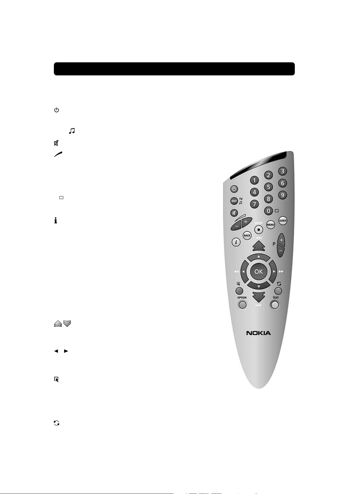
REMOTE CONTROL
This section describes how to operate the Mediamaster using the buttons on the remote control.
Some of the functions can also be carried out using the buttons on the front panel.
Switch the Mediamaster in and out of standby mode.
EXIT TV Return to the viewing mode from a menu without storing
any settings (in menu mode).
Switch between TV or Radio mode (in viewing mode).
Turn the sound off/on (mute).
- + Adjust the volume of digital programmes.
The Mediamaster’s maximum level is controlled by the TV’s
present volume setting.
0 - 9 Change channel and to select individual menu options.
0 TV Release. To switch between digital TV/Radio, analogue
BACK Go back one level at the time within menus without storing
pad Personal Active Disc. Call up (and hide) the recording menu
MENU To show and to exit from the Main Menu.
GUIDE Obtain a list of present and following programmes for the
P+ P- Change channels up and down, one at the time.
▲ ▼ Move up/down in the menus and to change channels.
Note: If 0 is entered as the first digit, the TV Release functionality is activated (see below).
TV and analogue satellite TV and VCR, when your systems
are connected by SCART cables.
Info. To display short and extended information (if transmitted) about current and next programmes.
any settings.
on the screen. For recording to the built in hard disk.
available channels. This information is only shown if your
Service Provider transmits programme information (EPG information).
Return to TV mode from an “Open TV” application.
Change page in a menu/list/text if more than one page is
available. To browse through teletext history.
Change settings in menus.
OK Confirm choices and selection of a highlighted item.
Show the TV/Radio channel list.
(Red) Download an “Open TV” application.
OPTION (Green) Select service options in viewing mode.
OPTION + code will open locked channels.
TEXT (Yellow) Select teletext information.
Press to enter teletext (if available).
(Blue) To toggle between present and previous TV/Radio
channel.
GB 5
Page 6
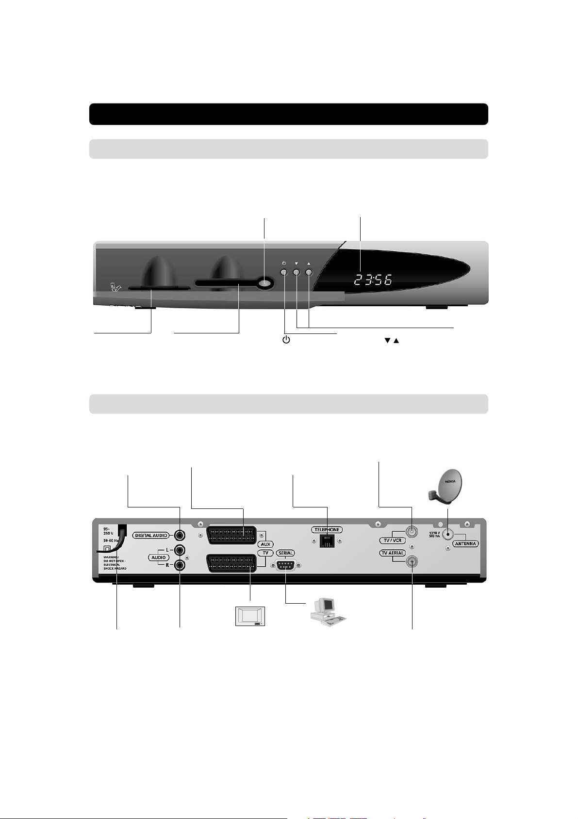
FRONT AND REAR PANEL
Front panel
Slot
for a Viaccess
Smartcard
Rear panel
DIGITAL AUDIO
phono connector
S/PDIF digital output for connection
to a HiFi system
Button
Push the button to
release an inserted
CA module
Slot
for a CA module
with a Smartcard
AUX SCART
for connection to a VCR,
or an analogue satellite
receiver
Display
shows channel number, error messages,
remote control commands and time in
standby mode
to put the Mediamaster
in and out of standby
mode
TELEPHONE *
for connection
of a modem
cable to the
phone jack
to move up/down in
the menus and to
change channels.
TV/VCR
for an RF-cable to the
aerial input of the TV or
VCR
ANTENNA * *
Satellite dish
input (F-connector)
Mains lead
95-250 V AC
50-60 Hz
* The modem function is only valid in
Scandinavia.
AUDIO L R
phono connectors
Stereo outputs for
connection to a HiFi
system
GB 6
TV SCART
for connection
to the TV
* *The LNB cable also feeds the LNB with a supply volt-
SERIAL PORT
to read and load
data information
TV AERIAL
for a terrestrial (conventional) TV aerial
age of 13/18 V (V/H polarisation) and a 0/22 kHz signal (bandswitch). Max LNB current is 500 mA.
Page 7
ABOUT THE SMARTCARD AND CA MODULE
To be able to receive scrambled digital satellite channels you will
need a Smartcard and/or a Common Interface CA (Conditional
Access) module* from the Service Provider of your choice.
The Service Provider is the programme distributor.
If you are subscribing to services from more than one Service
Provider, you might have to change between different Smartcards and/or CA modules.
Please note that a Smartcard and CA module may only be valid
for a single Service Provider and due to this, a specific range of
channels.
The Smartcard and the CA module may also provide access to
special menus not described in this manual. If so, please follow
the instructions from the Service Provider.
Only ”free to air” channels are available without the Smartcard
and/or the CA Module.
Note: The Smartcard and/or the CA module are distributed by
your Service Provider.
After inserting the card, leave it in the slot permanently. Do not
remove it again, unless your Service Provider asks you to do so.
This is important, because if your Service Provider wants to
download new information to the Smartcard, the card has to be
in the slot.
* Only use a DVB Standard Common Interface CA Module
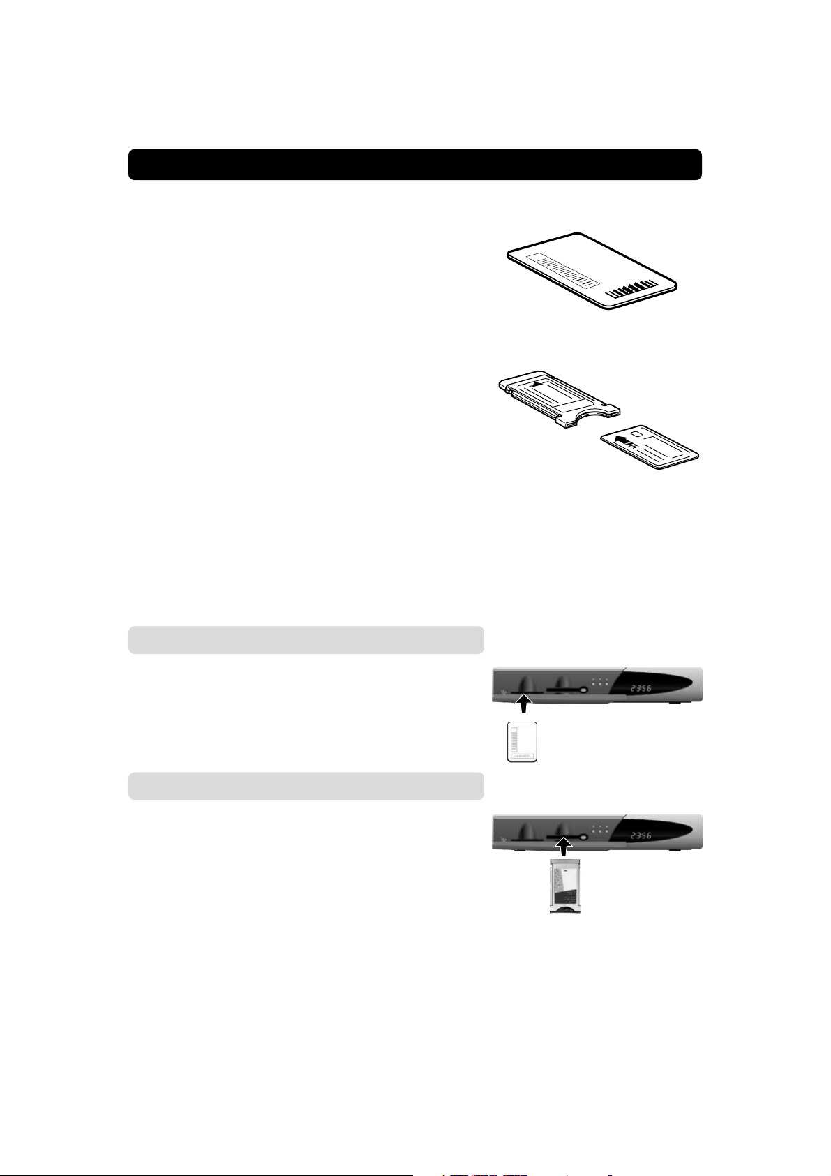
Viaccess smartcard
Only for services coded with the Viaccess CA system.
• Insert your Viaccess smartcard fully into the left slot behind the
lid of the front panel of the Mediamaster. The gold chip should
face downwards and inwards.
CA module with its smartcard
• Follow the instructions from your Service Provider how to insert the CA module and the belonging smartcard
• Insert the CA module fully into the slot behind the lid of the
front panel of the Mediamaster.
• Press the grey button on the front panel if you need to remove
the CA module.
PIN Code
The Smartcard is loaded with a 4-digit code, also called a PIN code
(Personal Identification Number).
The code is essential in order to access future services offered
by the Service Provider.
GB 7
Page 8
INSTALLATION OF THE MEDIAMASTER
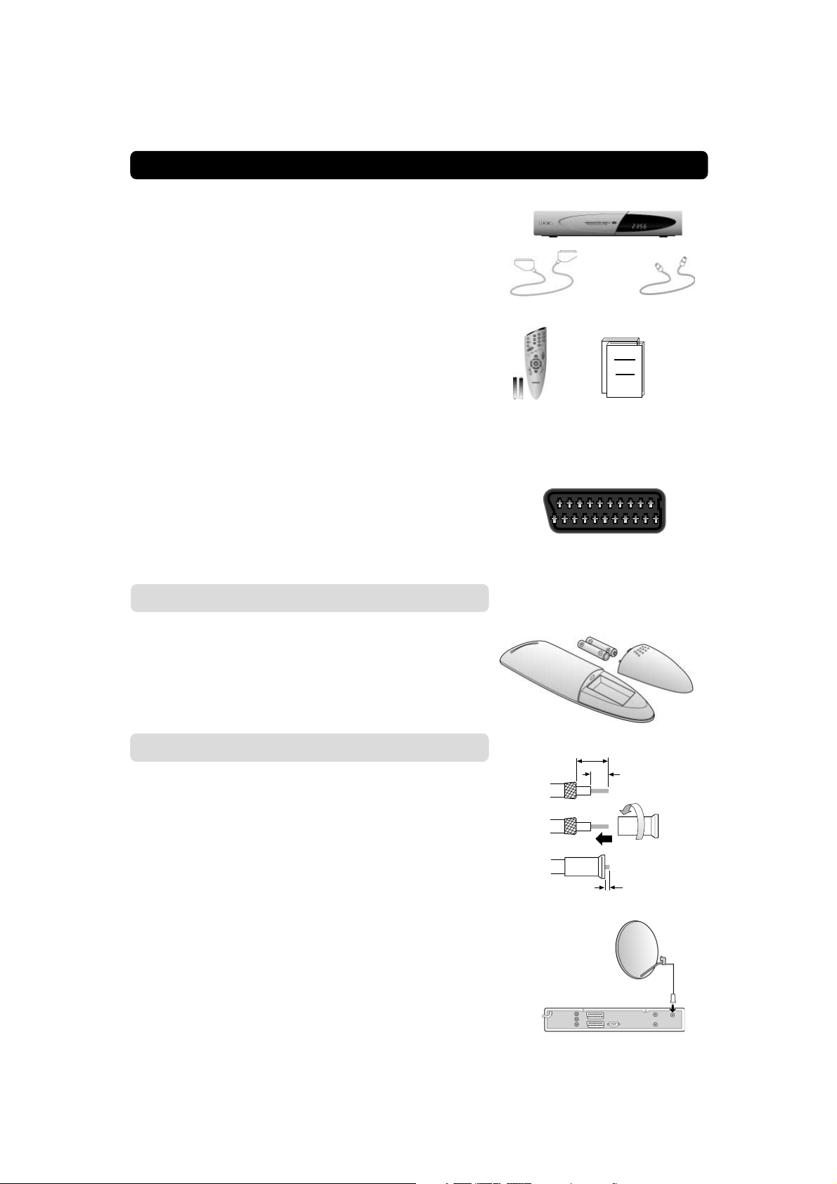
The box for your Mediamaster should contain the
following items:
• the Mediamaster
• remote control with 2 AAA batteries
• SCART cable (fully featured 1,0 metre)
• aerial/RF cable (double screened 1,5 metres)
• owner’s manual and software license agreement
SCART cable
RF cable
About the SCART sockets
The rear panel of the Mediamaster is equipped with 2 SCART
sockets (see diagram). When you connect other products to any
of these sockets, always use fully featured SCART cables (as
supplied). There are “less well specified” SCART cables on the
market and picture quality could be reduced if you use them.
Preparing the remote control
• Remove the cover on the battery compartment at the bottom
of the remote control.
• Insert the 2 AAA (1,5 V) batteries, as shown in the diagram,
taking care to observe the + and - markings indicated inside.
• Replace the cover.
Connecting the Mediamaster to the dish
If you need to fit the F-connectors onto the cable
• Prepare each end of the cable as shown in the diagram. You
will need to fold back the outer braid (as shown).
• Slide the F-connector onto the cable, then turn it clockwise
until it grips the braid.
• Ensure that 3 mm of the core is protruding from the end of the
connector.
Remote
control
Owner’s manual,
License agreement
SCART socket
15 mm
8 mm
F-connector
3 mm
Installing the satellite dish
• See the ”Fitting instructions for satellite dish” on how to in-
stall the dish.
• Connect the coaxial cable, with F-connectors fitted, from the
LNB on the satellite dish to the socket marked ”ANTENNA”on
the rear panel of the Mediamaster.
GB 8
Page 9
INSTALLATION OF THE MEDIAMASTER
General
There are many different types of TV/VCR and other equipment
that you can connect to the Mediamaster.
In this manual you will see some of the most common ways to
connect your equipment.
If you use RF cables you will have to tune your TV and VCR to the
Mediamaster output channel (see page 11).
If you have problems with your connections and need help, contact your dealer or Service Provider.
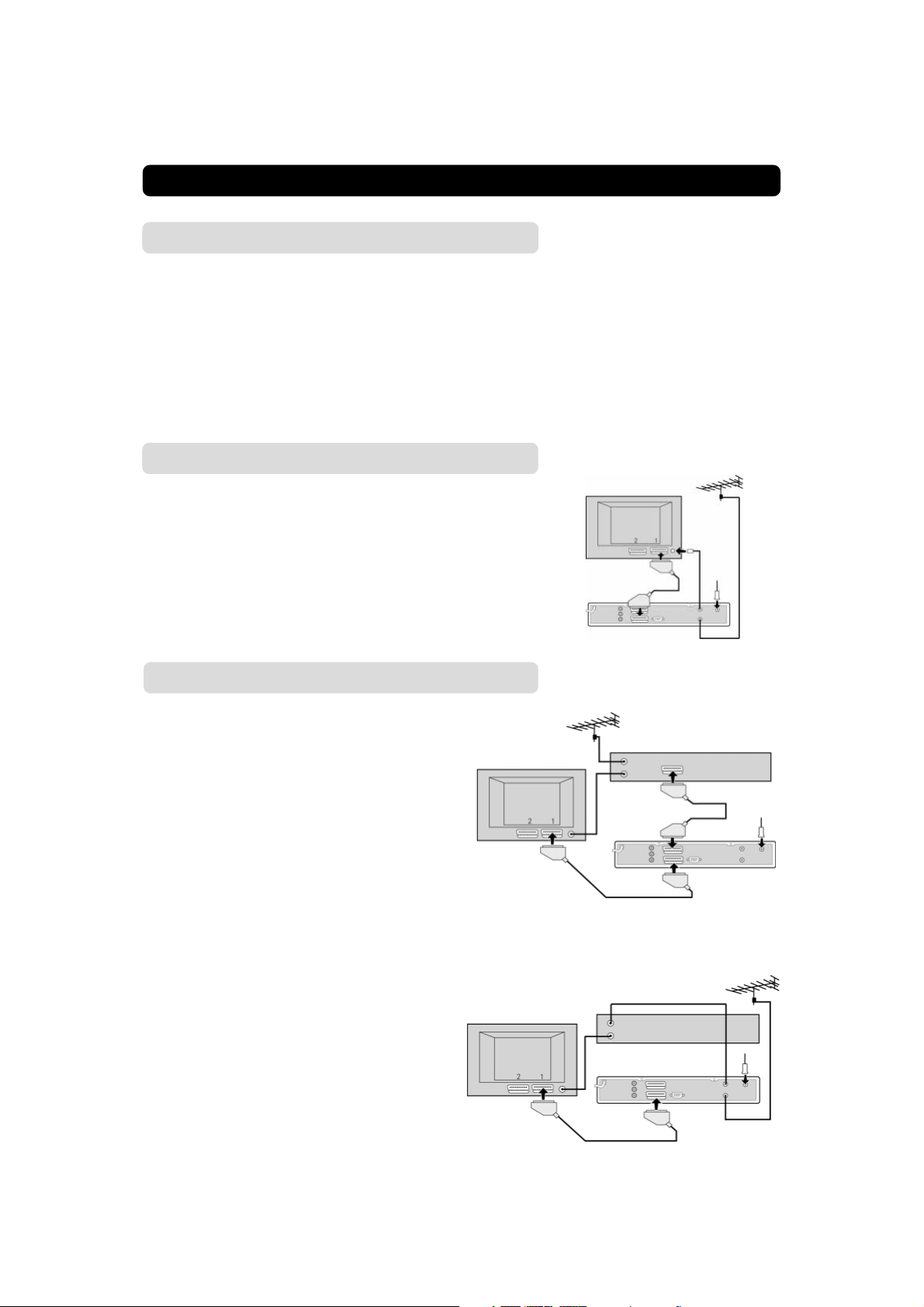
Connecting to the TV
• Connect the SCART cable between the main SCART socket
on the TV and the TV SCART socket on the Mediamaster.
• Connect an RF cable from the TV/VCR output on the Mediamaster to the RF input socket on the TV.
• Connect the TV aerial to the TV AERIAL input socket on the
Mediamaster.
SCART
RF
Connecting a TV and VCR
Refer to your VCR’s manual for full instructions.
• Connect one SCART cable between the main SCART socket
on the TV and the TV SCART socket on the Mediamaster.
• Connect another SCART cable between the VCR
and the AUX SCART socket on the
Mediamaster.
• Connect the RF cable from the RF output on the
VCR to the TV aerial input on the TV.
• Connect the TV aerial to the RF input socket on the VCR.
If your TV has a SCART socket, but your VCR does not
• Connect a SCART cable between the main SCART socket on
the TV and the TV SCART socket on the Mediamaster.
• Connect an RF cable from the RF output on the
VCR to the TV aerial input on the TV.
• Connect an RF cable from the TV/VCR output on
the Mediamaster to the RF input socket on
the VCR.
• Connect the TV aerial to the TV AERIAL input
socket on the Mediamaster.
RF
SCART
RF
SCART
VCR
SCART
Mediamaster
RF
VCR
Mediamaster
GB 9
Page 10
INSTALLATION OF THE MEDIAMASTER
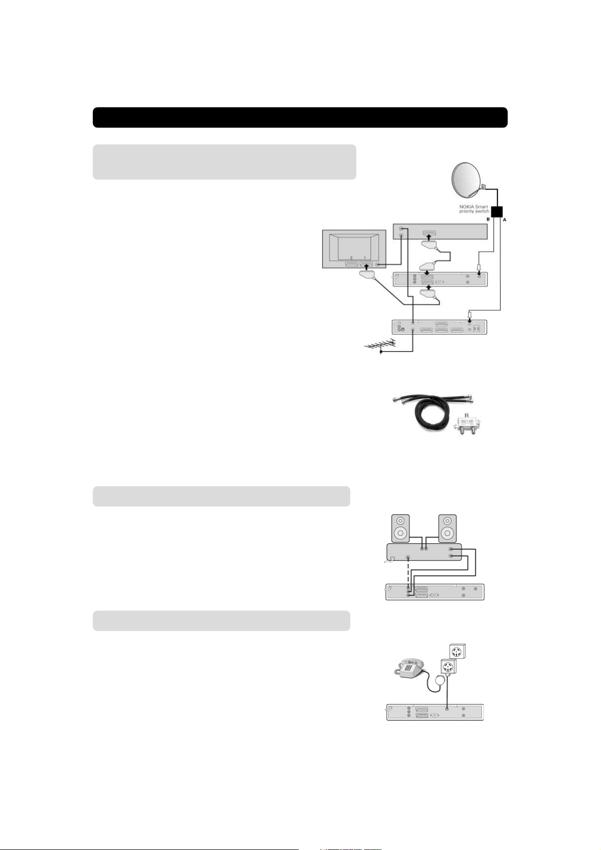
Connecting an analogue satellite receiver
and a VCR
• Connect a SCART cable between the main SCART socket on
the TV and the TV SCART socket on the Mediamaster.
• Connect a SCART cable between the VCR and the AUX SCART
socket on the Mediamaster.
• Connect an RF cable from the RF output on the
VCR to the TV aerial input on the TV.
• Connect an RF cable from the RF output on the
analogue receiver to the RF input socket on the
VCR.
• Connect the TV aerial to the RF input socket on the analogue
receiver.
In order to switch the signal from the dish between the analogue and digital receivers, you need a Nokia smart switch (at
A B in the diagram) or a Universal Twin LNB.
Nokia smart switch
• Connect a coaxial cable between output A on the smart switch
(accessory) to the LNB socket on the analogue receiver.
• Connect a coaxial cable between output B on the smart switch
to the ANTENNA socket on the Mediamaster.
With Nokia smart
switch
RF
VCR
SCART
Mediamaster
Analogue receiver
The analogue receiver must be switched OFF (in standby)
when you want to watch digital satellite channels from the
Mediamaster.
Connecting a HiFi system
• Connect an RCA/Cinch stereo cable from the AUDIO L R sockets on the Mediamaster to the LINE, AUX, SPARE or EXTRA
input sockets on your HiFi system.
• If available you can connect an RCA/Cinch single cable from
the DIGITAL AUDIO socket on the Mediamaster to your HiFi
or Dolby Pro Logic system.
Note: To avoid interference you must use a screened audio
cable.
Connecting to the built in phone modem
The modem function is only valid in Scandinavia.
The built in phone modem makes it possible for you to use interactive services. Refer to page 48. This function is only implemented in boxes intended for the Scandinavian countries.
• Connect a telephone cable between the socket marked
TELEPHONE on the rear of the Mediamaster and the ordinary
telephone socket in the wall.
Nokia smart switch
GB 10
Page 11
INSTALLATION OF THE MEDIAMASTER
Switching on for the first time with SCART
connections
• Plug in your Mediamaster
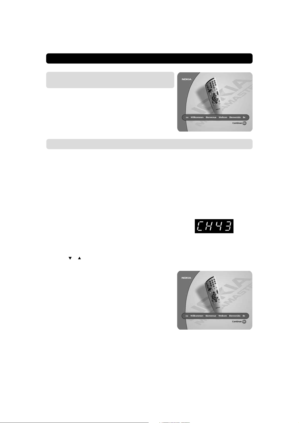
• Now you will see the ”Welcome” menu on the screen.
• Press OK on the Mediamaster remote control to start the In-
stallation procedure.
You may now proceed to “First time installation”, see next page.
Tuning procedure when RF connections are used
This procedure is necessary if your Mediamaster is connected to the TV with an RF cable, and not via SCART.
To tune your TV to the RF signal you might also need your TV
manual in addition to this manual. The steps below explain what
to do if you have been unable to use SCART cables in your connection.
• Plug in your Mediamaster.
Tuning your TV to the Mediamaster
• Select a channel number on the TV that is not currently used
for other TV channels.
• Follow the instructions in your TV manual to tune the TV channel selector to UHF channel 43 (this is the Mediamaster’s factory preset UHF channel). If you are already using this channel, select another non occupied UHF channel between 21 to
69 on the TV.
• For example, if you select UHF channel 45 on your TV, you
must change your Mediamaster to the same channel.
Use the
or on the remote control, to change to the corresponding channel. You will see the UHF channel number displayed on the
front panel of the Mediamaster.
• When you have correctly changed the UHF channel number
you will see the ”
If there is interference from other channels you will have to
change the chosen UHF channel.
• Follow the instructions in your TV manual to store this UHF channel as the channel used by your Mediamaster. You will have to
select it when you want to watch digital TV/Radio channels.
• Once the welcome message is visible, press the OK button
on the Mediamasters remote control to start the “First time
installation” procedure, see next page.
or buttons on the front panel of the Mediamaster,
Welcome
” menu on the TV screen.
If for some reason you have to change the RF channel later,
you can do this by using the TV settings menu further on in
this manual.
If you have a VCR connected it must be tuned to a different
UHF channel (between 21 to 69) than the Mediamaster.
GB 11
Page 12
FIRST TIME INSTALLATION
General information
Once you have correctly connected the Mediamaster, you also
have to perform a “First Time Installation.”
During this procedure, helpful information is displayed at the bottom of the menus.
Please note!
The OK button always confirms a selection within these menus,
and pressing it will take you to the next step in the installation
process. However, and this is important, often more than one
value has to be entered in a menu. First, perform all necessary
settings on the different lines. Then, confirm them all simultaneously by pressing OK.
You can always go back to the previous menu by pressing the
BACK button.
Use the
line to another. Use to change settings.
You can also use the numeric buttons on the remote control to
select a line in a menu and to enter numeric values.
buttons to move upwards and downwards from one
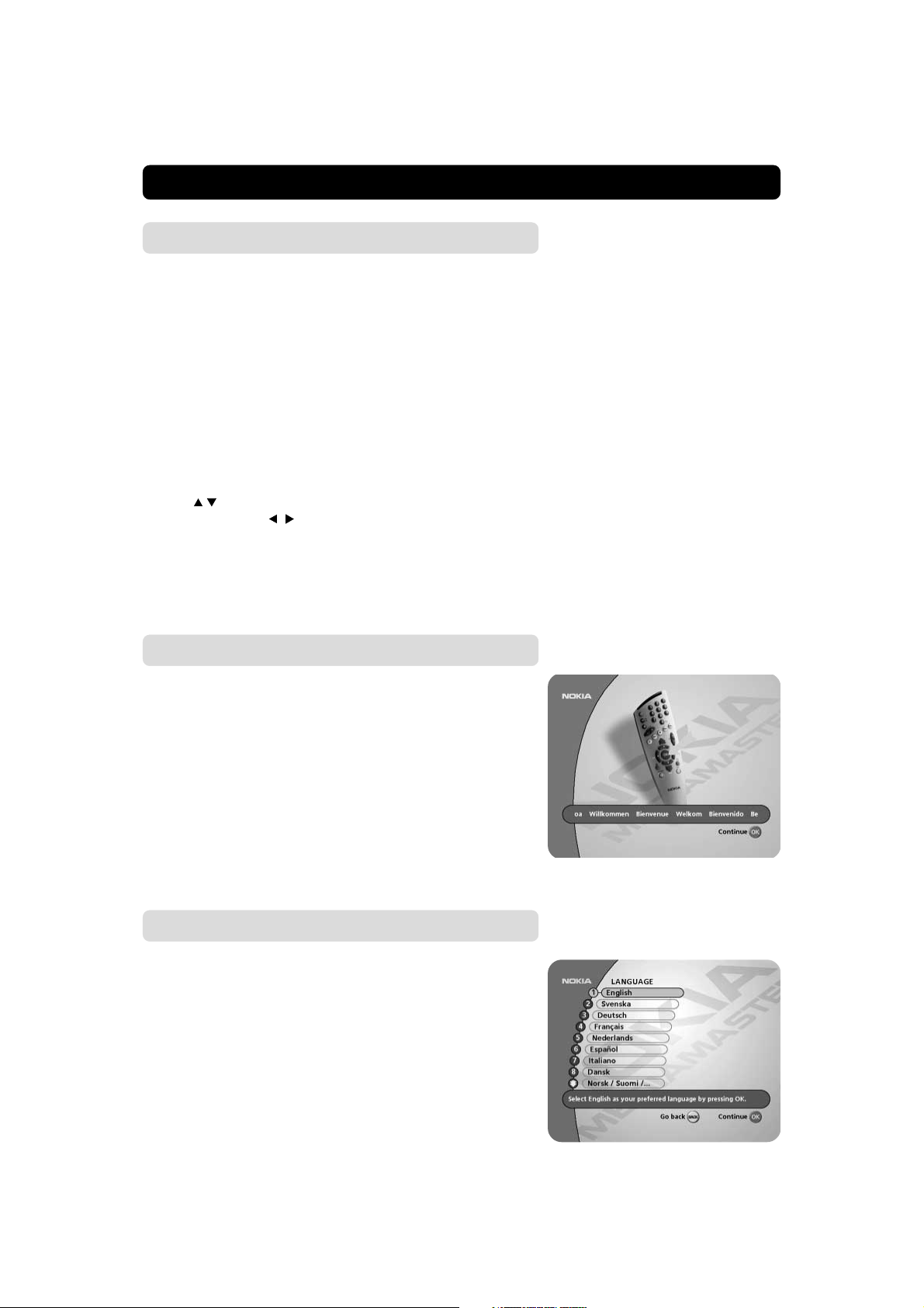
The “Welcome” menu
This picture indicates that you have started the installation procedure.
Press the OK button to proceed.
Language
Select the desired menu language.
This will also be the main language for audio and subtitling.
GB 12
Page 13
FIRST TIME INSTALLATION
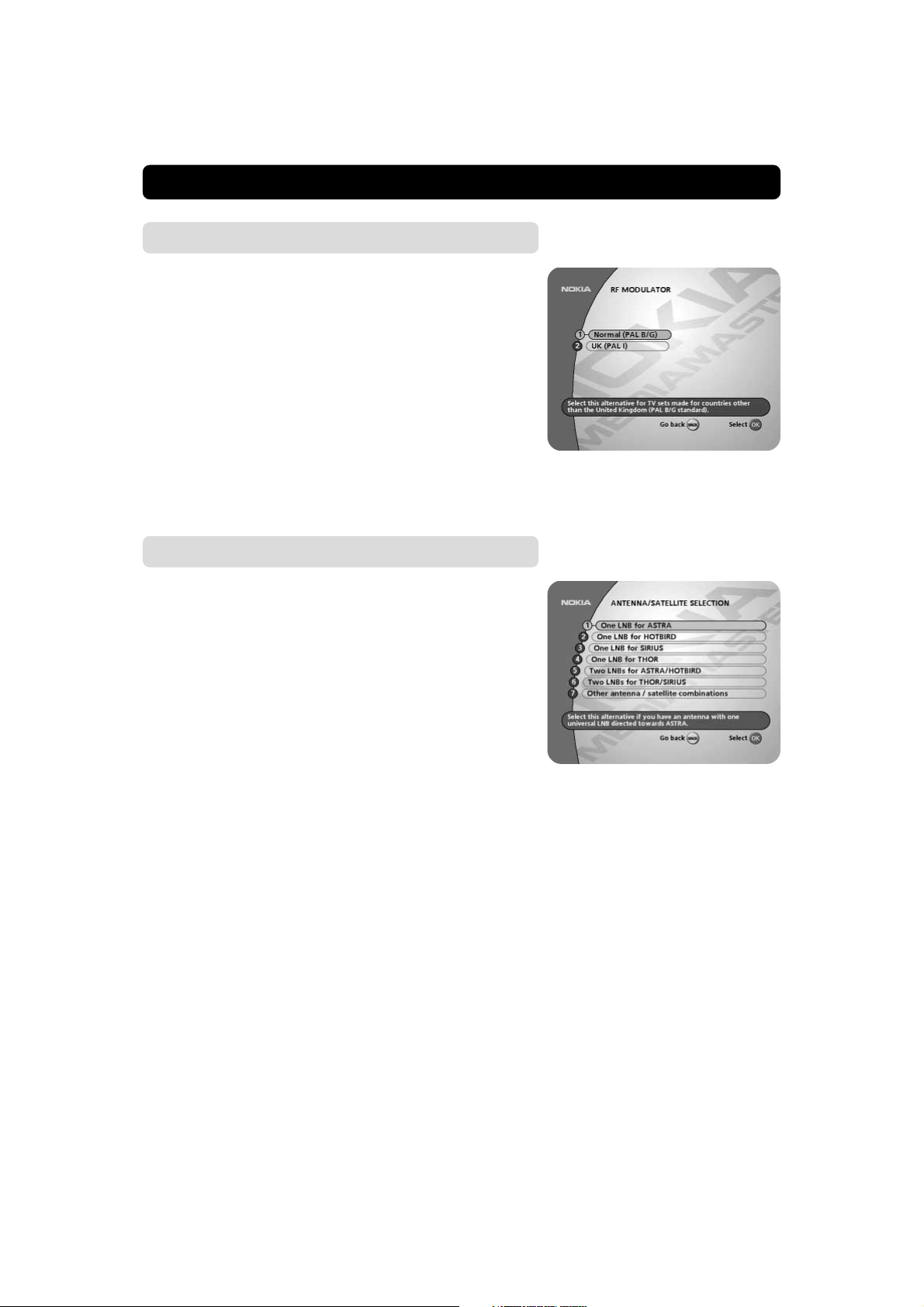
RF modulator type
If the Mediamaster is connected to the TV with a RF cable, you
must select the right RF modulator alternative, which is dependent on the country where the Mediamaster is being used.
Select “Normal (PAL B/G)” for all countries except the UK.
Select “UK (PAL I)” when the box is used in the UK.
If you get picture but no sound, the RF modulator selection might
be wrong.
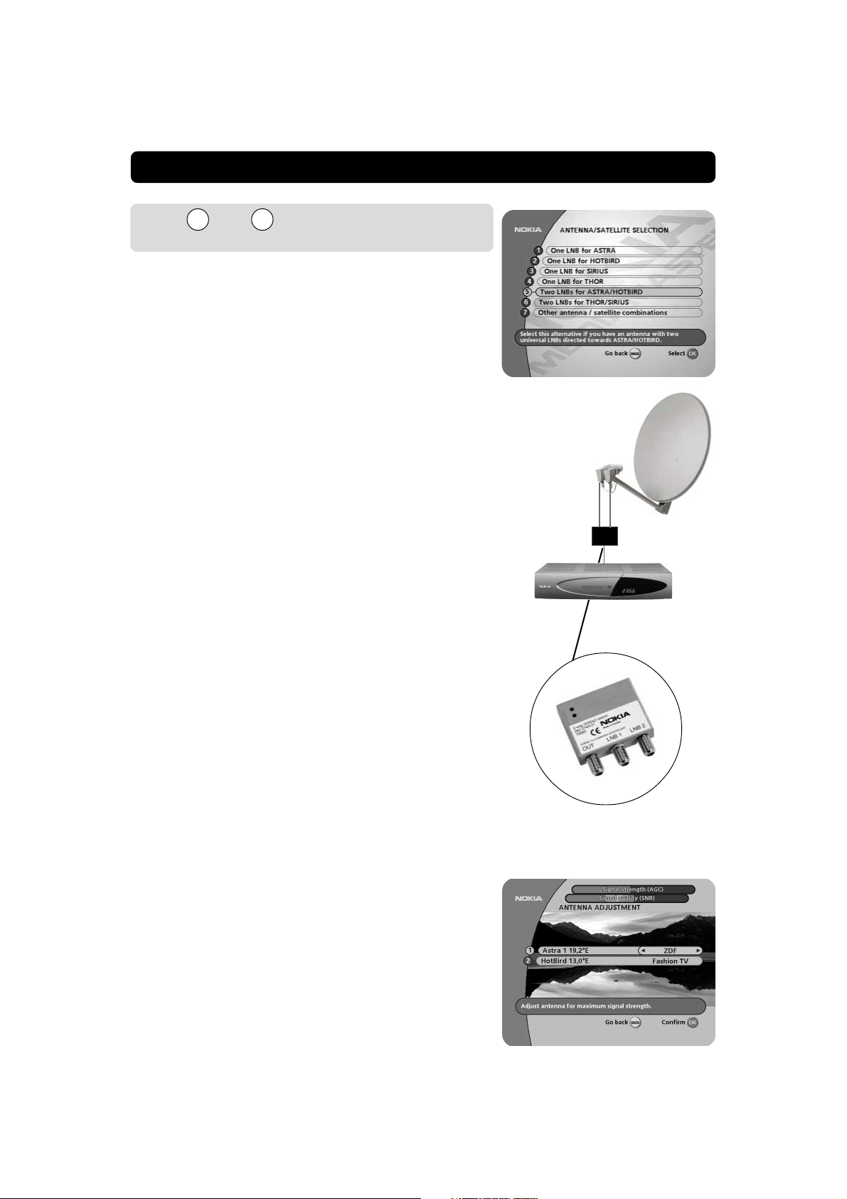
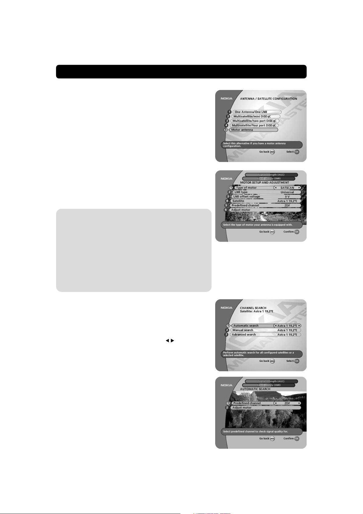
Antenna/satellite selection
Select one of the alternatives from line 1 to 4 if you have a single antenna equipped with one LNB for receiving signals from
either ASTRA, HOTBIRD, THOR or SIRIUS.
Select one of the alternatives from line 5 or 6 if you have one
antenna with two LNBs or two antennas with one LNB on each
for receiving signals from the combination ASTRA/HOTBIRD or
THOR/SIRIUS. In these cases you also need a 2-way DiSEqC
switch.
If you have an antenna with 4 LNBs select alternative 7. In this
case you also need a 4-way DiSEqC switch.
For any other antenna/satellite combination e.g. antenna motor,
select alternative 7.
Alternatives 1-6 requires the use of a Universal LNB(s.)
GB 13
Page 14
FIRST TIME INSTALLATION
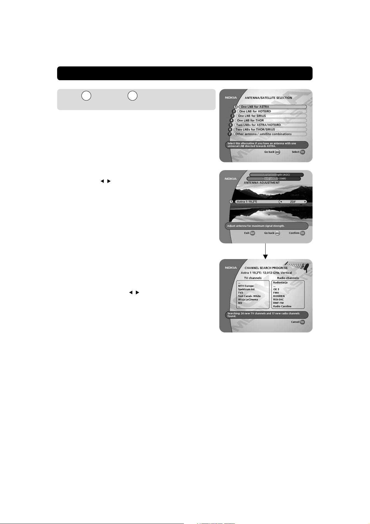
Line through on the antenna satel-
1 4
lite selection menu
Select one of the alternatives ASTRA, HOTBIRD, SIRIUS or THOR
when you have a single LNB pointed towards any of these satellites.
Pressing OK from the selected alternative will display the “Antenna adjustment” menu (shown to the right) on the screen.
For each satellite, (e.g. ASTRA, HOTBIRD, SIRIUS, THOR), up to
4 different channels are preprogrammed and shown in the menu.
When you adjust the antenna, your Mediamaster will use the
marked channel to find signals from a satellite. (You can select
channel with the
Antenna adjustment and signal check
• Adjust the antenna towards the desired satellite until you have
a high value on the Signal strength (AGC) *
bar at the top of the menu) and on the Signal quality (SNR) indicator (the red, yellow and green bar at the top of the menu).
If you do not get a picture, you may be tuned to an analogue signal source. Another reason could also be that the antenna is positioned towards the wrong satellite.
The reason could also be that the marked channel is not transmitting at the moment. If so, select one of the other preprogrammed channels with the
When you have picture from a TV channel, press OK. The Mediamaster automatically starts searching for and downloads channels from the satellite. Please refer to page 21.
(If you have a good indication of the signal quality, but no picture
from any of the channel alternatives, try proceeding with the
channel search anyway by pressing OK).
buttons.)
buttons.
)
indicator (the red
OK
*)About Signal strength (AGC)
and Signal quality (SNR)
The different signal indicators at the top of the menu provide information about two things:
AGC: The AGC, shown with a red bar, will indicate the average
strength of any incoming signal, digital as well as analogue.
SNR: The SNR, shown with a red, yellow and green bar, will
indicate the signal quality for the preprogrammed
channel chosen.
GB 14
Page 15
FIRST TIME INSTALLATION
Line and on the antenna satellite
5 6
selection menu
Select one of these alternatives when you have a single antenna
equipped with 2 LNBs, or two antennas with one LNB on each,
and want to watch channels from ASTRA/HOTBIRD or THOR/
SIRIUS.
In this case you must first connect the LNBs to an external switch
since there is only one antenna input on the Mediamaster. Once
installed the switch automatically selects the correct LNB for the
selected channel.
This external switch is better known as a DiSEqC
the switch can be located close to the LNBs, you only need one
cable down to the Mediamaster.
Connection of a two port DiSEqC switch:
• Connect the cable from the LNB intended for channels from
ASTRA (or THOR) to the connector marked LNB 1 (A) on the
switch.
• Connect the cable from HOTBIRD (or SIRIUS) to the connector marked LNB 2 (B).
• Then, connect the antenna cable to the connector marked OUT
on the switch.
• Connect the other end of this cable to the ANTENNA input in
the rear of the Mediamaster.
TM
switch. Since
• First check, as described in paragraph Antenna adjustment
and signal check on page 14, that you get picture and sound
from ASTRA (THOR).
• When you have picture and sound continue to the next row
and check HOTBIRD (SIRIUS) for picture and sound.
• When the HOTBIRD(SIRIUS) check is ready, press OK to start
the channel search procedure. The box now starts searching
and downloading channels from both satellites. See “Channel
search” on page 18.
DiSEqC switch with 2 inputs
GB 15
Page 16
FIRST TIME INSTALLATION
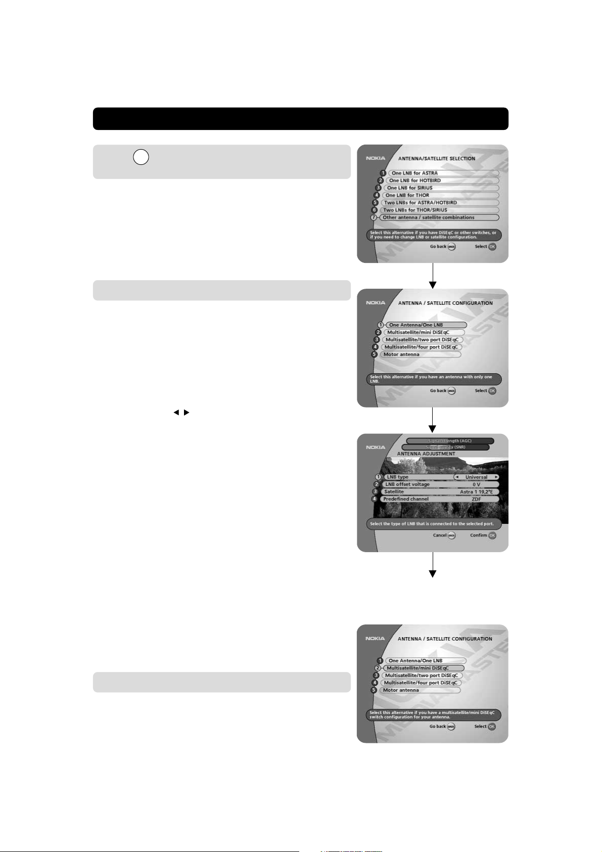
Line 7 on the antenna satellite selection
Menu
This selection is necessary only when your satellite choice differs from the preprogrammed satellite alternatives in the follow-
ing ways;
• if you do not use an universal LNB
• when you have more than two LNB’s.
• You also must select this alternative when your antenna is con-
trolled by motor (ref. to page 19.)
One antenna/one LNB configuration
Select this alternative if you have one (1) LNB mounted on the
antenna and you want to select another preprogrammed satellite (than those from line 1-4.)
You also must select this alternative when you are not using an
Universal LNB.
LNB type
Select the local oscillator (L. O.) frequency valid for the present
LNB. The most common values, including Universal LNB, are
selectable with the
You can also enter a value with the numeric buttons when the
symbol for the remote control is visible on the line.
LNB offset voltage
If the cable down from any of the LNB’s is very long, it might be
necessary to increase the voltage to these LNB’s by 0,5 V.
In most cases nothing has to be altered here. Leave the default
value “0 V” as it is. If the switch does not change between horizontal and vertical polarization, the voltage to a LNB can be increased later.
Increase the voltage:
a. only if a LNB does not change polarization
b. only to the specific LNB mentioned in a. above
Satellite
Select one of the preprogrammed satellites.
Predefined channel
Select one of the preprogrammed channels and adjust your antenna according to the “Antenna adjustment and signal
check” section on page 14.
buttons.
OK
OK
OK
Please follow the procedure described on page 14.
Multisatellite/mini DiSEqC
Select this alternative if you are using two LNBs that are controlled by a mini DiSEqC switch.
The selection of the different LNBs must be controlled by an
external switch. Refer to page 15.
GB 16
Page 17

FIRST TIME INSTALLATION
For each LNB you connect to the DiSEqC switch, the following configuration has to be performed.
As an example the following part will describe how the LNB in-
tended for Astra 1 will be configured to the DiSEqC input A on
the switch and the LNB intended for Hotbird to DiSEqC input B.
LNB type
Select “Universal” or the local oscillator (L. O.) frequency valid
for the connected LNB.
LNB Offset voltage
If the cable down from the antenna is very long, the voltage at
the LNB could be too low to change the polarization. You can increase the voltage to the LNB by 0,5 V.
Satellite
In this example, select Astra 1 because its LNB is connected to
the DiSEqC A input on the switch.
Predefined channel
Select one of the predefined channels and adjust the antenna as
described on page 14, “Antenna adjustment and signal check”.
Before you can continue, a TV picture from the predefined channel must be visible in the background.
When you do have a picture press OK to continue with DiSEqC
port B. The same procedure as for Astra 1 has to be repeted. But
this time select Hotbird as the satellite.
When the configuration of DiSEqC B is ready, press OK.
Proceed with the channel search. Refer to page 18.
Multisatellite/two port DiSEqC
Select this alternative if your antenna system has two LNBs and
when you are not using any of the alternatives on the lines
5 - 6 from the menu “Antenna/satellite selection” on page 13.
• Make the selections for LNB type, LNB offset voltage (if necessary), satellite and predefined channel (see Multisatellite/
mini DiSEqC above for an explanation of the different alternatives) for switch 1.
• Press OK.
• Make the selections for switch 2.
• Press OK.
Proceed with the channel search. Refer to page 18.
GB 17
Page 18
FIRST TIME INSTALLATION
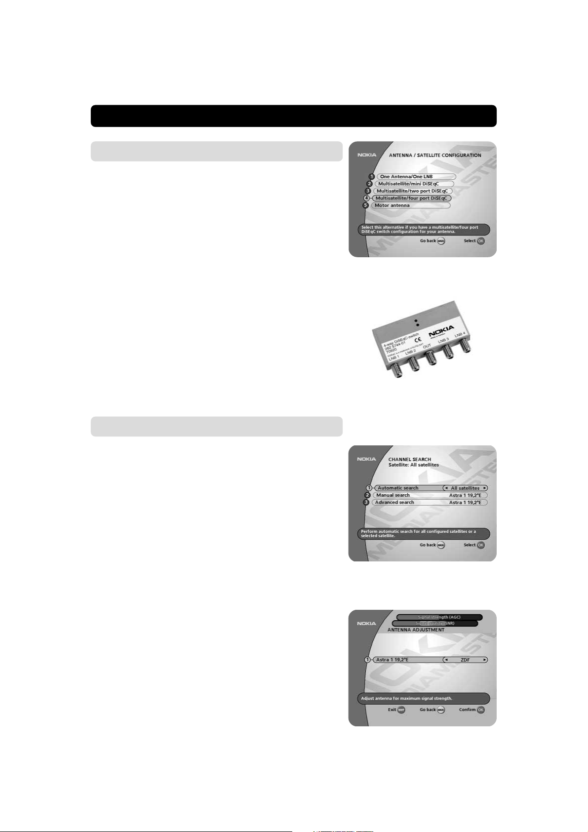
Multisatellite/four port DiSEqC
Select this alternative if your antenna system has four LNBs and
when you are not using any of the alternatives on the lines
5 - 6 from the menu “Antenna/satellite selection” on page 13.
The selection of the different LNBs must be controlled by an
external switch. Refer to page 15.
The procedure is the same as for mini DiSEqC and two port
DiSEqC, but you have to configure four LNBs the same way as
described on page 16-17.
Connection of a four port DiSEqC switch:
The following is an example of how you can connect 4 LNBs if
you want to watch channels from ASTRA, HOTBIRD, SIRIUS and
THOR.
Connect the LNBs to the switch the following way:
• the LNB intended for ASTRA to input 1
• HOTBIRD to input 2
• SIRIUS to input 3
• THOR to input 4
The output marked OUT on the switch shall be connected to the
ANTENNA input on the Mediamaster.
DiSEqC switch with 4 inputs
Channel search
The Channel search procedure can be performed in different
ways.
• If there are predefined channels, you can make an Automatic,
Manual or Advanced search.
• If no predefined channel is available you can make a Manual
or Advanced search.
Automatic search
Start an Automatic search on a selected satellite by pressing OK.
GB 18
Page 19
FIRST TIME INSTALLATION
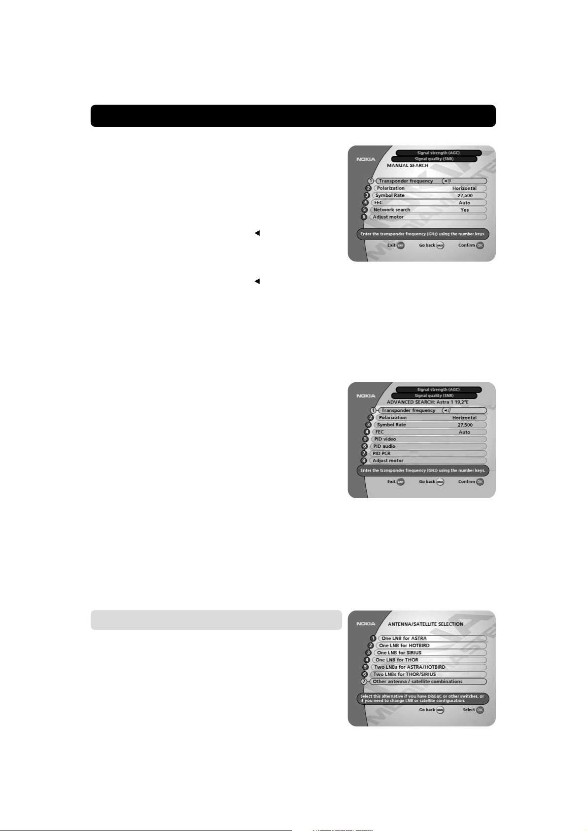
Manual search
When you perform a Manual search you first need to enter some
parameters for the channel search to work.
The information you need to enter in this menu is available in
magazines covering satellite TV reception, on the Internet or from
your Service Provider.
Transponder frequency: Specify the frequency in GHz. If you
enter the wrong figure(s), erase with the
Polarization: Select Horizontal, Vertical, Circular left or Circular
right.
Symbol rate (MSym/s): Enter with the numeric buttons. If you
enter the wrong figure(s), erase with the
FEC: Select “Auto” or any of the preprogrammed values.
Network search: Select “Ye s ” if you want to search on all trans-
ponders connected to a specific network.
Adjust motor: Adjust (if necessary) the motor for the current
satellite.
Press OK to start searching for channels.
Advanced search
The information to enter in this menu is available in magazines
covering satellite TV reception, or from your Service Provider.
You can use this menu if you are looking for some “special” channels (i.e. non-DVB standard channels) which can only be found
when you have entered the necessary settings here.
Transponder frequency: Specify the frequency in GHz.
Polarization: Select Horizontal, Vertical, Circular left or right.
Symbol rate (MSym/s): Enter with the numeric buttons.
FEC: Enter the appropriate Forward Error Correction (FEC) or
select AUTO
PID Video: Enter the PID (Packet Identifier) for the video signal.
PID Audio: Enter the PID for the audio signal.
PID PCR: Enter the PID for the PCR (Programme Clock Refer-
ence).
Adjust motor: Adjust (if necessary) the motor for the current satellite.
Press OK to start searching for channels.
button.
button.
Motor antenna
In case you have an antenna motor to control your satellite antenna you have to make the following settings. If your antenna
is prevented from reaching its east/west limit positions, you have
to set these limits. See page 47 for instructions.
• From the “Antenna/Satellite selection” menu select line 7 and
press OK.
• Select line 5, “Motor antenna” and press OK.
GB 19
Page 20
FIRST TIME INSTALLATION
Type of motor
• Select SATSCAN if it is a Nokia SatScan motor.
• Select DiSEqC in case the motor you use is controlled by
DiSEqC commands.
LNB type
• Select Universal, one of the fixed frequencies or enter the LNB
frequency with the numeric buttons on the remote control.
LNB offset voltage
If the cable down from the antenna is very long, the voltage at
the LNB could be too low to change the polarization. You can increase the voltage to the LNB by 0,5 Volt.
Satellite
Select Astra if you have a SatScan motor and Hotbird if you have
a DiSEqC motor.
Adjust motor for Astra/Hotbird
To continue the installation you now have to determine
the angle to Astra 1/Hotbird. The motor and the antenna
must be adjusted towards the Astra 1 satellites on 19.2
East (Hotbird satellites on 13° East) as this is the refer-
ence setting. All other preprogrammed satellite positions
are oriented relative to Astra 1/Hotbird.
You also have to mount the antenna at a proper place
outdoors.
How to do all this, please read the separate fitting instructions for the SatScan or DiSEqC positioner.
°
Predefined channel
Select the predefined channel that will give the best Signal quality (SNR) bar indication. Within a few seconds you will get picture
from the channel in the background.
Adjust motor
• If necessary, fine tune the motor with the buttons on the
remote control.
As you now have a picture in the background, it is time to perform a Channel search procedure.
• Press OK......
....and you will get the Channel search menu.
The most common is to start from the “Automatic search” line.
(You can always make a Manual or Advanced Search later on.)
• Select the satellite you want to use on the Automatic Search
line, for example Astra.
• Press OK......
.......and you get the Antenna adjustment menu.
• If necessary, adjust the motor until the Signal strength (AGC)
and the Signal quality (SNR) are optimal. Please note, that this
will only affect the present satellite position.
GB 20
Page 21

FIRST TIME INSTALLATION
• Select one of the Predefined channels and press OK to.....
.....start the main search procedure for (in this case) the ASTRA
channels. The search procedure will take a while. Please refer to
page 22.
When the channel search from ASTRA is finished you can search
for channels from other satellites if you have a motor antenna.
• Press MENU on the remote control and the Main menu will
appear on the screen.
• Select line 5, System configuration
• On demand, enter the Access code 1234....
......and the System configuration menu will appear.
• Select Channel search
• Press OK to get the Channel search menu again.
GB 21
Page 22

FIRST TIME INSTALLATION
The position of 22 satellites are preprogrammed in the SatScan
motor.
As long as you select satellite positions from the line “Automatic
search” you also have access to preprogrammed TV channels
that makes it easy to check the signal quality.
• From line 1 Automatic search, select the satellite from which
you want to search for channels.
Then the procedure is the same as for the first satellite installation.
However, you must give the antenna motor some time to
turn itself to the new position!
Channel search progress
This menu will be shown as long as the Mediamaster is searching for channels to download
All channels found will be listed in two columns on the screen;
with TV channels in one column and radio channels in the other.
Please note that the search procedure may take a few minutes.
When the search procedure has ended, a message will tell how
many TV and radio channels have been found.
Press OK to continue.
Time adjustment
The time is adjusted by using the buttons, ±1/2 an hour at a
time.
You can also adjust the minutes by using the buttons.
Press OK to finish the first time installation, see below.
Finishing the first time installation
The channels found at the search procedure will now be saved.
A message telling that the installation procedure is completed will
be shown on the screen.
Press OK in order to start watching channels from the box.
GB 22
Page 23

VIEWING MODE
General information
The following describes the basic functions of your Mediamaster
while watching satellite TV or listening to satellite radio.
Some of the functions described here are dependent on the
Service Provider and can only be used if they are included in
the transmitted programme information.
Please note, that during the Channel search procedure, the
Mediamaster may have downloaded a large number of channels.
This may include channels from various Service Providers, also
those to which you do not have access unless you have a
Smartcard from one of those Service Providers.
If you select a programme to which you do not have access, you
will get a message on the screen. This message may vary, depending on Service Provider and used Smartcard/CA module.
While viewing, the current channel number will be shown on the
front panel display.
In addition to the normal functions like switching the Mediamaster in/out of standby, changing the volume etc. there are also
other useful functions which will be explained in this part of the
manual.
You can always leave a menu at any time you want, without affecting any settings, by pressing the EXIT button.
Programme information
Channel
list
Information
about the
current programme
Every time you change channels you will receive programme information for a few seconds. (In the “User preferences” menu
you can select how long this information will be shown.)
The information may include:
Current time.
Channel list.
Channel number and name.
Name of the current and next programme.
The start and total time of the current programme.
A bar, indicating the elapsed time of the current programme.
Recommended lowest age limit for watching the programme.
The start and total time of the next programme.
Programme information will only be available if it is included
in the transmission. Otherwise a “No information available”
message will be shown.
You may change channel lists with the
buttons.
This symbol will be shown in the upper left corner of the screen
when a downloadable application (”Open TV”) is included in a
channel transmission.
To close an application and return to watch TV, press the P+ or
P- button on the remote control.
Please refer to page 51 for more information.
Current
time
Channel number
and name
Information about
the next programme
Press the red button on the
remote control to start
downloading an “Open TV”
application
Age limit
information
GB 23
Page 24

VIEWING MODE
The “i” (information) button
The Mediamaster has the ability to display information about programmes currently being broadcast as well as those being broadcast next.
This procedure is the same for both TV and radio mode.
By pressing the “i” button while watching TV you will get a special “Programme information” banner. Select channel with
or the numeric buttons.
The “i” symbol is coloured blue when displaying information
about the current channel, and red when information for another
channel is shown.
Press “i” again to get more information about the current programme.
If a lot of information is available you can use the double arrow
button to see the rest of the text.
Press “i” a third time to return to TV/radio mode.
In this view, you can select to get information about the current
and next programme by using the
You can leave the menus at any time and return to viewing TV by
pressing EXIT.
buttons.
GUIDE
By pressing the GUIDE button you get access to the
Mediamaster TV guide (or Radio guide if you are listening to ra-
dio channels) which will give the titles of the current and next
programmes on different channels. The information is only available from the network (e.g. DF1, TPS) to which the channel you
are watching belongs.
Use the
Use the double arrow buttons to move a page at a time up and
down.
When a line is highlighted, you can get more information about
this programme by pressing the “i” button.
When you are watching a channel from Viasat while pressing the
GUIDE button, the Viasat Portal will be shown. Follow the instructions from there how to get programme information.
buttons to move the cursor to another programme.
GB 24
Page 25

VIEWING MODE
List of TV and radio channels
At the channel search procedure, three channel lists are created.
One list named “All TV” containing all channels, another named
“Free TV” containing only free channels and “Viasat” containing
channels distributed by Viasat.
In the “All TV” list scrambled channels are marked with a picture
of a Smartcard (if this information is transmitted in the signal) and
locked channels are marked with a padlock.
If you have performed a new channel search, the new channels
found will be marked with a star
When viewing TV or listening to radio channels you can access
the channel list by pressing OK. The lists are sorted by satellite,
network and channel.
At the top of the menu you will see the name of the list. The current list is the one in which the channel you are watching right
now is located.
• If the list contains a large number of channels, you can close
satellites or networks to reduce the number of channels. You
open/close a satellite or network by marking it and pressing
. A closed satellite/network is indicated with .
Change channel lists with
To open the radio channel list you first have to enter radio mode
by pressing “EXIT TV
” and then OK.
You can change channel by stepping with the
enter the channel number with the numeric buttons on the remote control.
Press OK when a channel name is highlighted to start watching/
listening to it.
To change one channel list page at a time, use the double arrow
buttons.
You can also get more information about a marked (highlighted)
channel by pressing the “i” button.
in the “All TV” list.
.
buttons or
Name of the
Channel list
Channel
number and
name
Indicates a
locked channel
Indicates a
closed satellite
Network
name
Indicates a
scrambled
channel
Options (green button)
By pressing the OPTION button, you open a menu in which it is
possible to enter temporary settings. The menu will only appear
if the programme contains any options to change. More alternatives than the below mentioned may be available.
Settings made in this “options menu” are only valid for the programme you currently are watching. If you leave the programme
and return to it again, the temporary settings will be gone.
Audio language
If available, you can select among the different languages being
broadcast.
Subtitle language
If available, you can select among different subtitle languages.
If you select “OFF”, you will not get any subtitling at all.
Format
If you have a TV set with a 4:3 picture format, and the transmission is in 16:9, you can select Fullscreen or Letterbox to change
display format. Fullscreen will fill up the screen vertically, but cut
off some information from the left and right sides of the picture.
Letterbox will give a complete picture, but leave black areas at
the top and bottom.
GB 25
Page 26
VIEWING MODE
TV release (0)
With the 0 button you can toggle between analogue terrestrial
TV, video, analogue and digital satellite TV signals.
(This is only valid if the units are connected via SCART cables, and
not by a RF connection.)
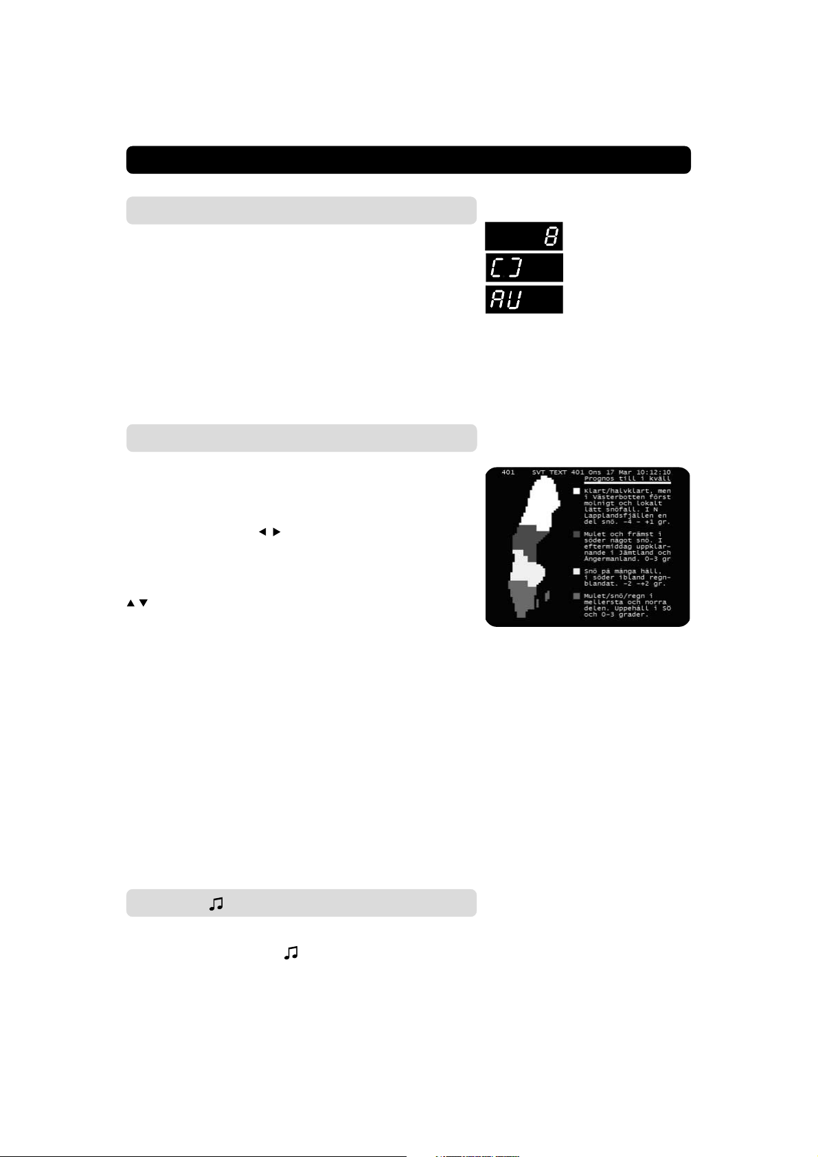
The TEXT button (teletext)
Pressing the TEXT button will open a teletext page (if teletext is
transmitted.) Select teletext pages with the numeric buttons on
the remote control.
You can also quickly step to the different page alternatives shown
in any page by pressing
go to that page.
Press EXIT or BACK to return to TV/radio mode.
The “0” button will show the index page (normally page 100.)
will show the next or previous teletext page.
You can use the double arrow buttons to browse through the
pages you just have visited.
When “hidden text” is applicable it can be shown by pressing the
“i” button.
On most new TV sets you can use the TV’s remote control to
open and control the teletext functions while watching digital TV
channels. (The function is called VBI insertion.) NOTE: Also see
“Subtitles”settings on pages 50 and 51.
. Press OK on a selected number to
Channel number
Analogue TV mode
Video mode. (The video
must be turned ON)
EXIT TV
This button has double functions.
While watching TV: The TV/ function is used to switch from
TV to radio mode and vice versa.
When you have entered a menu, the EXIT function is used to
leave the menu at any time without changing anything.
GB 26
Page 27

VIEWING MODE
Recording on an external analogue Video
recorder
Please note, that during the recording of a programme, everything shown on the screen will be registered! For example, if you
call up a menu from the Mediamaster on the screen, the menu
will be recorded!
When recording digital channels from the Mediamaster and the
Videorecorder is connected with a SCART cable: put the video
into AV/AUX or E1 mode.
When recording digital channels from the Mediamaster and the
Videorecorder is connected with a RF cable: you must give the
Mediamaster an own position number on the video. (The same
way as you probably already have given e.g. SVT1 and other channels their own positions.)
Recording from the hard disk to a video recorder
You can also transfer recordings made on the hard disk to the
videorecorder. Select a recording made on the hard disk and start
the playback of it. Depending how the boxes are connected, via
a SCART or RF cable, you now can make a recording on the
videorecorder .
GB 27
Page 28

HARD DISK RECORDING
About hard disk recording
As you probably already know this box is equipped with a built
in Personal Active Disc. This is a hard disk, similar to those in ordinary Personal Computers (PCs). On this hard disk it is possible
to record about 15-20 hours of TV and radio programmes.
To get the most out of the disk recording procedure, follow these
simple tips to keep the disk well prepared for coming recordings.
In this way you will avoid messages on the screen saying things
like “Time available: Less than 1 hour” 5 seconds before you want
to make a two hour recording from a live performance of your favourite pop group; or “The current recording was stopped because there was not enough space on the disk”. As we all know,
those messages always appear when we least want them to.
• Make a practice to clean the disk from recordings that are no
longer needed.
• Recordings that you want to keep, you can transfer to a tradi-
tional analogue Video Recorder. Recordings made to the built
in disk can not be digitally transferred to an external hard disk.
• A good thing to do now and then, is to erase everything from
the disk (select “Erase hard disk” from the “System Configuration” menu.) But remember, absolutely everything will be
erased.
• We suggest that you spend some time testing all functions un-
til you get familiar with them. This will save you a lot of frustration when the moment for making and watching a recording becomes reality. After the practice you can just erase the
disk and it will be ready to start from scratch.
It is important for you to also be aware of the following
facts concerning the hard disk recording
• Only the channel whose number is shown in the display on the
box can be recorded. This means, that you can not watch e.g.
channel 4 and record e.g. channel 8 at the same time.
• A big benifit that the built in hard disk possess, but the ana-
logue video recorder lacks, is the possibility for you to start
watching the playback of a programme while the recording of the same programme is still in progress. This possi-
bility is utilized at the “Pause recording” procedure which is
described further on in this manual.
• Note! Pause recordings will not work if you are watching
a programme ordered via KIOSK (Canal Digital’s pay-perview).
• CAUTION! Unauthorized recording of TV programmes or
other material may infringe the copyright and be contrary
to the copyright laws.
GB 28
Page 29

HARD DISK RECORDING
Different ways of making recordings
There are three ways of making a recording. In this manual they
are separated in the following way:
1 A Pause recording
This function is useful when you make a break while watching TV. We will describe how this function can be used when
you get a phone call.
2 A Normal recording
Spontaneously start a recording at any time you want. As you
will see, the procedure differs a bit from the Pause recording.
Please try not to mix them, because if you do, it might lead to
some confusion.
3 A Timer recording
Use the Timer function to record programmes automatically
when you are not at home.
The recording menu
This is the recording menu. You call up the menu to the screen
by pressing the
The menu has to be visible before you can start a recording.
Good to remember: You can always show and hide this menu by
pressing the
The menu will not be recorded.
The symbols
mally handled with the arrow buttons on the remote control. As
this is the most convenient way, only the button commands will
be explained in this manual.
button marked “pad” (Personal Active Disc).
button.
represent functions that are nor-
Locked functions during recording
Most functions are locked when a recording is in progress. It is
not possible to call up any other than the recording menu. If you
try, you will get the message “You can not do this as long as the
disk is active”. The only functions that are active during a recording in progress, except the different alternatives in the recording
menu, are volume, mute and TV release.
It is possible to watch another recorded program during a pause
recording.
GB 29
Page 30

HARD DISK RECORDING
The Pause ( ) Recording
To describe this, let us say that the phone starts to ring while you
are watching TV. You do not want to miss anything of the programme, so you decide to make a pause recording. To start it you
only have to press two buttons on the remote control.
• First, call up the recording menu by pressing
• Then, start the pause recording by pressing OK.
• The picture will freeze and the sound will be turned off at the
moment the recording starts.
• Answer the phone.
During a pause recording the menu looks like the one in the figure to the right.
• At the very bottom of the menu there will be a bar showing
the total time of the recording.
• Above the bar, “Pause” indicates that a pause recording is go-
ing on.
• Above it, there are two time counters, separated by a / (slash.)
The right counter will continuously show the recorded time in
hours, minutes and seconds. (The left one will be explained
later on.)
• The recording menu will automatically disappear after about
5 minutes.
• When you start a pause recording, the display on the box will
change to indicate “PAUS” instead of the channel number.
.
To watch the pause recording
Now, 10 minutes later, when you return after having finished the
phone call, the situation is like this:
• A frozen picture on the TV and no sound. That is all.
Of course, you now would like to watch the pause recording that
contains your missing 10 minutes.
• You start the playback of the pause recording by first pressing
(to pick up the menu) and then press OK. Of course, if the
menu still is visible when you return, you only have to press
OK.
Now it is important for you to be aware of the fact that the
recording is still in progress. It has not yet been turned off.
Therefore the right counter will show an increasing recording
time. But this is quite all right. We let you know how and when
it is time to turn it off.
GB 30
Page 31
HARD DISK RECORDING
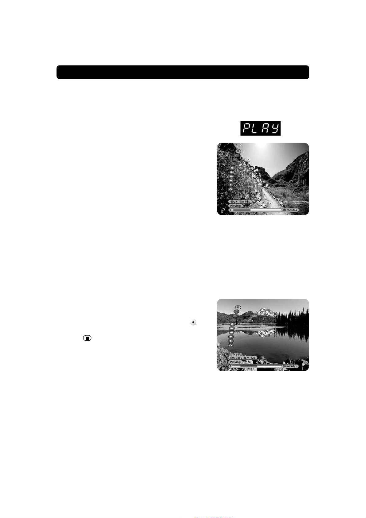
What is happening during playback of a pause recording
that is still in progress?
When the playback starts, a few other things also happen at the
same time.
• Although the pause recording is still going on, the display now
will start to show “PLAY” instead of “PAUS”.
• The text at the bottom of the recording menu now will start
to show “Playing” instead of “Pause”.
• At this moment, when you start a playback, the left counter
starts to show elapsed time of the playback.
• The right counter continues to indicate recorded time.
• The bar at the bottom of the page will show elapsed time
(green) and total time (red).
Now let us stop for a moment and analyse the situation. What is
happening? As a matter of fact, two different things are now in
progress simultaneously:
• The pause recording is still going on,
• and you are watching the playback of it, with 10 minutes de-
lay.
To finish this example of a pause recording
• Keep on watching the playback until the programme reaches
the end, for example after 5 minutes.
• The left counter will now show 5 minutes, which is the length
of the playback.
• The right counter will show 15 minutes because the record-
ing process has been going on all the time.
• Now you finish this pause recording by first pressing
up the recording menu to the screen, then
• select “
• This pause recording is now finished and stored in the “List
of recordings”.
There also is another way to finish the pause recording. More
about that soon.
” in the menu and press OK.
to pick
GB 31
Page 32
HARD DISK RECORDING
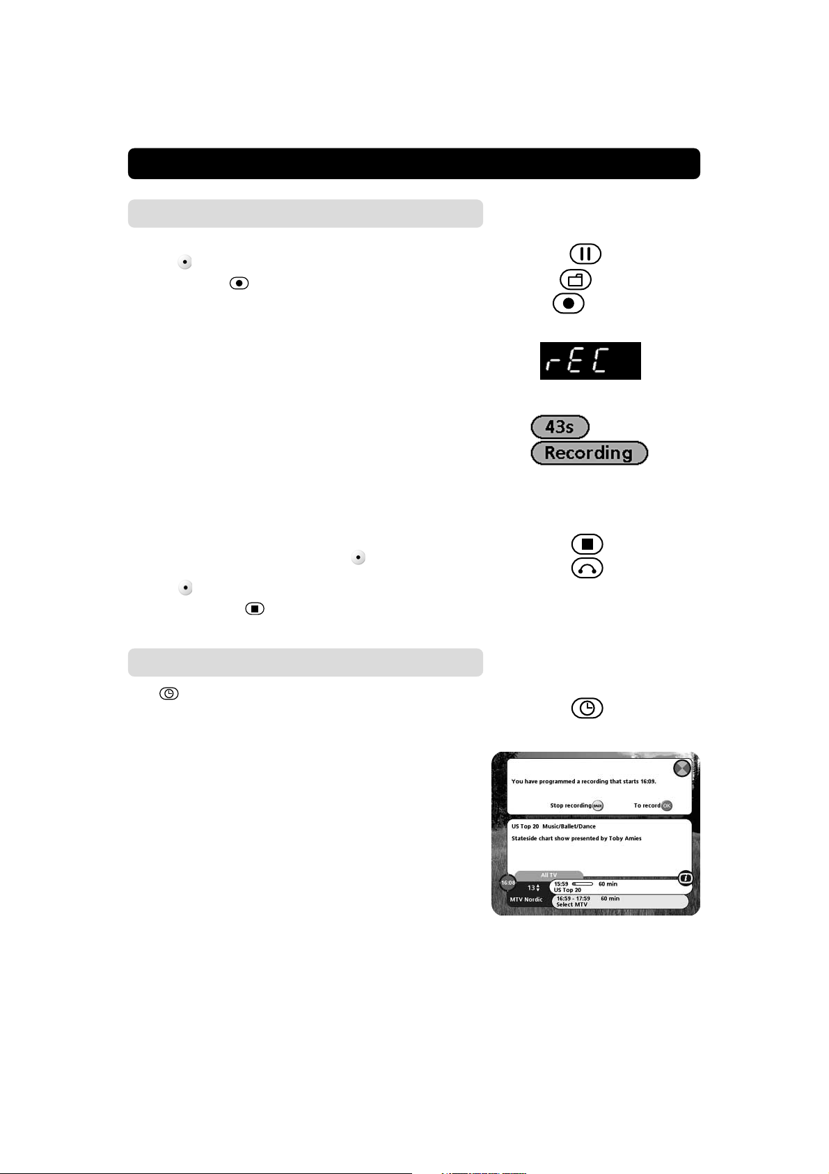
The Normal recording
When you want to perform what we call a Normal recording.
• Press
• Step down to “ ” in the menu.
• Start the recording by pressing OK.
• The display on the box will show “r E C” during this type of
recording.
• If you press the green button on the remote control while a
recording is in progress you can preset the recording time. This
is called OTR (one touch recording). There are preset times in
30 minute steps up to 240 minutes. Each time you press the
green button you will add 30 minutes to the recording time.
When the preset recording time is reached, the recording will
stop automatically. The display on the box will show “r XXX”
during this type of recording. XXX is the time you have set for
the recording.
• During the recording, elapsed time and the information “Re-
cording” will be shown in the recording menu. If you have
used the OTR function described above, you will also see how
much time that is left until the recording stops.
• Finish the recording by first pressing
ing menu. (If it is already on the screen, you do not have to
press first!)
Then check that “
lect it) and then press OK.
on the remote control to pick up the recording menu.
to call up the record-
” is highlighted in the menu (if not, se-
Timer recording
The “ ” alternative in the recording menu is a short cut to the
“Timer” menu. From there you can program the box to perform
recordings when you are not at home.
Please refer to the “Timer setup” described on page 56.
For your information, in case you are at home watching TV when
a timer recording starts:
Shortly before a timer recording starts, the message in the right
figure will be shown. Press OK if you want the recording to take
place; press BACK if not. (You will be asked just in case you are
watching a more interesting programme than the one that is to
be recorded.)
When you do nothing the recording will start in a moment.
GB 32
Page 33

HARD DISK RECORDING
To start playback of a recording
You find a finished recording in the List of recordings which you
reach by
• Pick up the recording menu to the screen by pressing
• Select from the menu to pick up the List of recordings
to the screen
• Step to one of the recordings with and press OK
• The Handle Recording menu appears
• Select Play and the playback starts
• The left counter starts to show elapsed time
• The right one shows the total length of the recording and the
elapsed time in %
The pause function
It is possible to make a pause during a playback of any recording.
A pause causes the picture on the screen to “freeze”.
Pause during playback of a normal recording
• First call up the recording menu by pressing
• Start the playback of a programme from the List of recordings.
• Alternate between playback and pause mode by pressing OK.
Pause during playback of a pause recording in progress
The pause function is possible to use also while a pause recording is still in progress. Note, that the right counter will be active
all the time due to the fact that the recording is still in progress.
• First call up the recording menu by pressing
• Start the playback of the pause recording by pressing OK, and
also the left counter starts.
• Alternate between playback and pause mode by pressing OK.
GB 33
Page 34
HARD DISK RECORDING
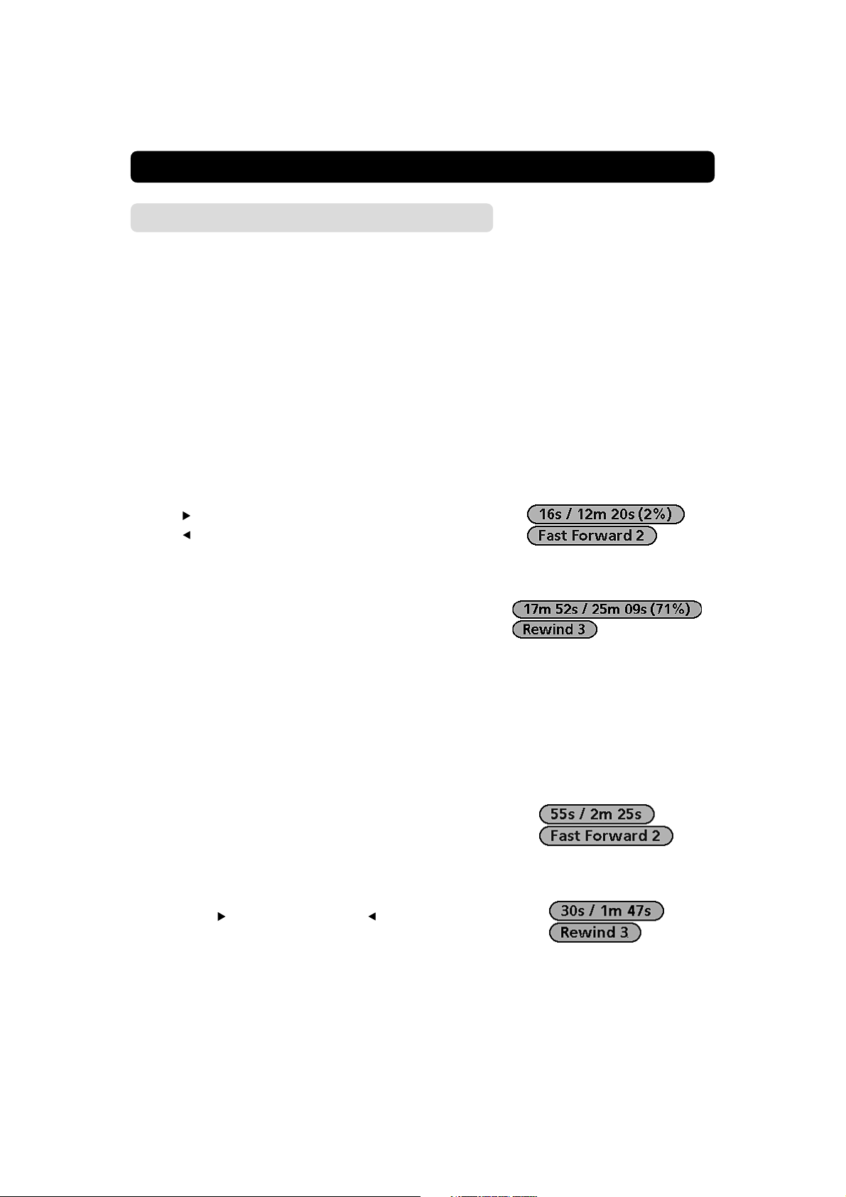
Watch the playback at a different speed
To speed up a playback or to find a certain position in a recording, you can use functions such as
• Fast forward
• Rewind
• Slow motion
The functions can be performed not only during a normal playback, but also during a pause recording in progress.
Fast Forward and Rewind during playback of an already
finished recording
While watching the playback of a recording you can start Fast
Forward or Rewind by pressing the appropriate button.
You do not even need to have the recording menu on the screen.
• Press
• Press to start Rewind.
• The playback will now speed up, either forwards or backwards.
• If you press the buttons repeatedly the speed will increase. At
the bottom of the menu there is now an indication showing
the speed, e.g. “Fast Forward 2”. The speed may be set between 1 (not so fast) and 9 (very fast).
• If the speed is too high in any direction, just use the opposite
button to slow down.
• To stop and return to normal speed, press OK.
to start Fast Forward.
Fast Forward and Rewind of a pause recording in
progress
The Fast Forward function is useful when you just want to skim
through e.g. a short pause recording, that is still in progress, in
order to catch up the live broadcast of the programme. When you
reach the end of a pause recording it will automatically finish and
the live programme will be shown instead. (Unless you have
changed the default setting for this in the “Digital Recording Preferences”, Line 5, on page 55.)
• First you must start the playback of the pause recording in
progress by pressing OK.
• Then, press
• The playback process is the same as described for the normal
playback.
• Note, that the left counter will follow the Fast Forward/Rewind
process while the right one will keep on showing recorded
time for the pause recording in progress.
• To stop the Fast Forward/Rewind and return to normal playback
speed, press OK.
GB 34
to start Fast Forward or to Rewind
Page 35

HARD DISK RECORDING
The Slow Motion function
The Slow Motion function is a way to watch a playback in a
slower way than the normal playback speed. This function is the
same for all types of recordings. It only works in the forward direction, never backwards.
To playback in Slow Motion mode:
• First you must start the playback of a recording.
• Then put it into pause mode by pressing OK.
• Start the function with any of the
them to control the speed, which is from +3 to -5, where +3
is half of the playback speed and -5 is really slow.
• Exit the Slow Motion mode and return to normal playback
speed by pressing OK.
Small steps during playback
To move small steps forwards or backwards during a playback you
can use the double arrow buttons. The will step 20 sec. forwards and will step 10 sec. backwards.
buttons. You also use
Find a specific position within a playback
If you have a very big recording and want to reach a specific position of it, the Fast Forward or Rewind functions might be a bit
inconvenient to use.
Instead you can use thejump function .
• Start a playback.
• Select “
• From line 1, Jump to position, you can select one of the
predefined times with
number buttons on the remote control. Please note, that the
start position for the “jump” is the beginning of the programme. If you watch a playback for 25 minutes and from
there select to jump e.g. 1 hour on line 1, you will reach a position 1 hour into the programme, not 1h. 25 minutes.
When you want to jump to an exact position, e.g. 1 hour 3 minutes and 7 seconds, enter 010307. Always 2 figures for each
hour, minute and second. When you want to jump e.g.
12 minutes and 32 seconds, enter 1232.
If you enter a wrong digit, remove it with
• Line 2 and 3, Jump Forwards/Backwards: Select one of the
predefined times with
number buttons on the remote control. In any of these cases
you will jump forwards or backwards from the position
where the playback is right now.
” from the menu.
, or enter an exact time with the
.
, or enter an exact time with the
GB 35
Page 36

HARD DISK RECORDING
The Edit ( ) function
It sometimes happen that some extra minutes from the programme that starts after or before the one you want to save also
will be recorded. If so, you can use the
you the opportunity to erase parts in the beginning and at the end
of a recording. You can also split a recording into two separate
recordings. Note! It is important that you have at least 8 Mb space
left on the hard disk in order to split a file. If you don´t, you will
get a message telling that the disk is full. Erase some files in order to make some more space and try to split the file again.
• Start the playback of the recording.
• Make a pause when you reach the section from where you
want to erase or split.
• Select “
• You can now erase everything (within the recording) before or
after the point where you made the pause. Or you can split the
recording into two different recordings, one is ending at the
point where you made the pause and one is beginning at the
same point. Confirm your choice by pressing OK.
You can also add together two different recordings into one recording. See “Add another recording” on page 38.
” from the recording menu and press OK.
function. It will give
GB 36
Page 37

HARD DISK RECORDING
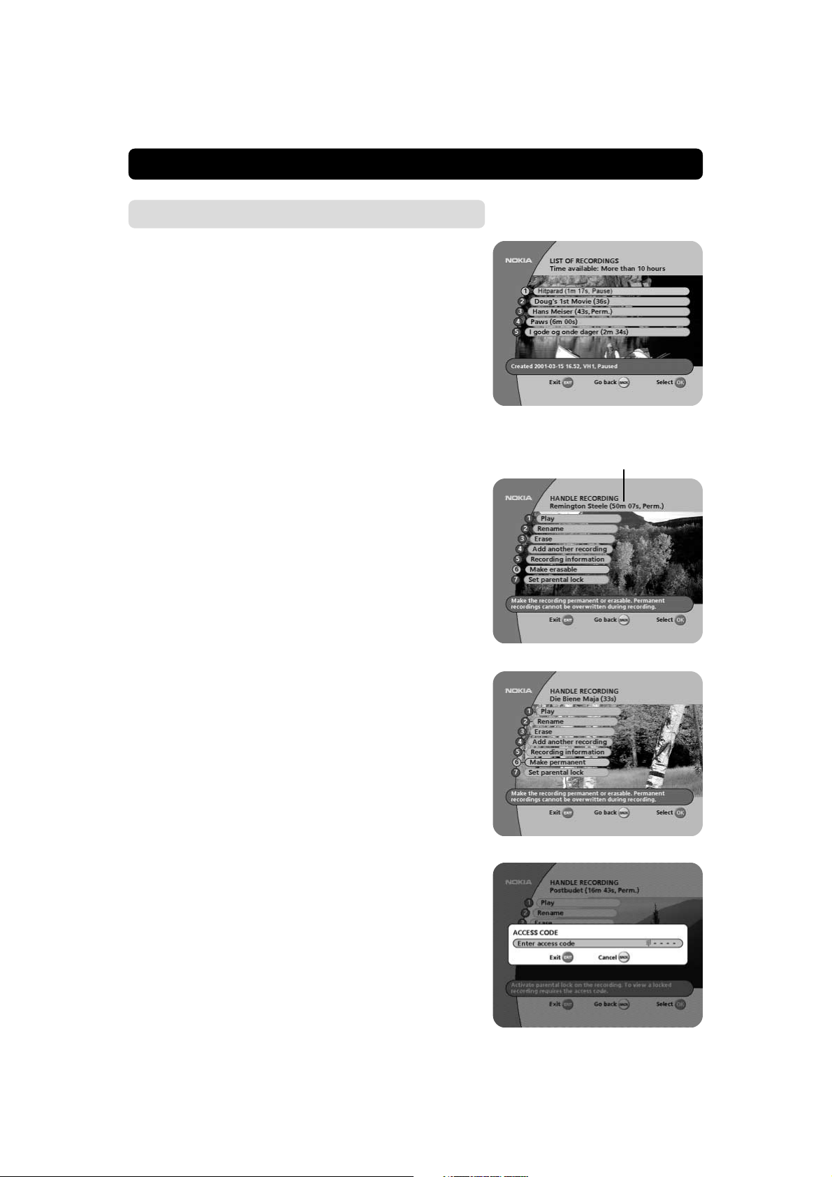
List of recordings ( )
As mentioned earlier, all recordings will be stored in the List of
recordings.
To reach it, select “ ” from the recording menu.
In addition to the recordings, the List also contains an important
information about the disk:
• Time available: Here you will be informed about the estimated
time available on the disk. You must be aware of that the time
indication is a really rough estimate, but it will give a hint of
available time.
The settings in “Recording preferences” will in a very high
degree affect what will be shown here. (Ref. to page 52.)
In the green information field, at the bottom of the menu, some
information about the different recordings is shown. Press the “i”
button to get more detailed information. (On condition that the
information is included in the programme transmission.)
The List of recordings may consist of up to 64 pages with 7 recordings on each. On each page, the list is numbered from
1 to 7. Fresh recordings will be saved on page 1. The older the
recording, the higher the page number.
Step between pages with the double arrow buttons.
Handle recording
By selecting any of the recordings from the List of recordings and
pressing OK you get the Handle Recording menu. Besides the
fact that you start the playback of a recording from here, you also
have the possibility to change the properties of the recording.
Play
Start playback. Refer to page 33.
GB 37
Page 38

HARD DISK RECORDING
Rename
You can give the recording a new name. Note that the first lines
contains only channel information and are not possible to rename.
• Step to the last line and press OK.
• To enter the new name, please follow the instructions for “Re-
name Channels” on page 42.
The new name that you enter will now be shown in the List of
recordings.
Erase
Enter this menu when you want to clean up the disk from certain
recordings. Before you erase a recording you will get a chance
to regret the deletion by selecting BACK. Select OK and the recording is definitely gone.
Add another recording
You can add a recording to another using this alternative.
• Select the recording you want to add another recording to from
the list of recordings.
• Press OK.
• Select Add another recording and press OK.
• Then select the recording you want to add from the list of re-
cordings.
• Press OK. The second recording will be added after the first
recording.
The two original recordings disappear from the list and you now
have only one recording containing both of the original files. The
recording will have the same name as the first selected recording.
If you want to add more recordings, you just follow the same
steps.
Recording information
Available information about the recording will be shown. The details are dependent of what was included in the programme transmission at the time for recording.
GB 38
Page 39
HARD DISK RECORDING
Save a recording as Erasable or Permanent
To avoid that a Pause or Normal recording will be erased, it is a
good idea to change its property from erasable to Permanent.
Default property for a pause recording
When a pause recording is created, in the List of recordings it will
automatically get the extension (......Pause) at the end of its
name.
The number of pause recordings in the List of recordings will be
kept constant to the limit you have defined in “Saved Pause Recordings”, ref. to page 52. In practice, this means that pause recordings are continuously erased to keep that limit.
Default property for a normal recording
A recording created the normal way has no extension. This
means that it is erasable, but will remain on the disk until it is full.
When the disk space is not enough for a new recording, also
these recordings (without any extension) will be erased.
How to change the property to erasable or permanent
• Select a recording from the List of Recordings and press OK.
• Immediately below the name of the menu “Handle Record-
ing”, the current property for the recording is always visible.
• Step to line 6.
• By pressing the OK button you can now change the property
between erasable and permanent and vice versa. The valid
property will immediately be visible below the “Handle recording” name. The text “Perm.” within the brackets
means Permanent, and no text means Erasable.
The event property of a recording
will always be shown here.
Summarize
A recording can have one of the following three characteristics:
1 A pause recording will always be automatically erased in or-
der not to exceed the value you once have decided. This type
of recording has the extension “Pause” at the end of its name
in the List of recordings.
2 A recording can also be erasable and automatically deleted, but
not until the whole disk is filled upp with recordings. This type
has no extension.
3 The third type of recording has the extension “Perm” at the
end of its name. This one must always be manually erased.
Set parental lock
When you want to lock a recording, select this alternative and you
will be asked to enter your access code. After entering the code,
the recording is locked. To watch it you must enter the code again.
(The code is the same as for the Parental Control.)
GB 39
Page 40

MAIN MENU
General information
Many of the functions of the Mediamaster are available from the
Main menu.
Press MENU to open it.
You can always leave a menu at any time you want, without affecting any settings, by pressing the EXIT button.
TV and radio channels
Please refer to “List of TV and radio channels” on page 25.
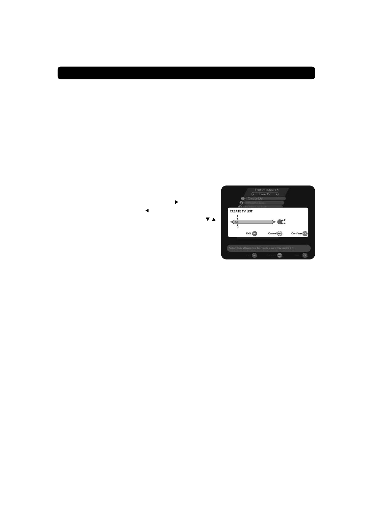
Edit channels
From these menus you can create and edit channel lists. You can,
among other things, create favourite lists; add, delete, rename
and arrange the order of the channels within the lists.
The “All TV” list might contain lots of channels. By creating your
own favourite lists you can make channel handling a bit more convenient.
Important about editing channels
Before you start you must select which list, TV or radio, you want
to edit. While you are watching TV and press the MENU button
and select Edit channels, you can edit TV channels. While listening to radio channels and doing the same, you can edit radio channels.
After the selection, radio or TV, use the
mote control to select the name of the list to edit.
GB 40
buttons on the re-
Page 41
MAIN MENU
Create list
From here you create your own favourite lists, containing the
channels you watch most frequently. You must give each list a
specific name, e.g. “Sport” or “Films.”
When a favourite list is selected, you see only those channels
defined in the list.
When you have given the list a name; press OK and you will enter the “Select channels” menu (see next page) from where you
add channels to the list.
You can create separate favourite lists for TV and radio channels.
How to give a specific name
This procedure is the same whether you enter a name for the first
time or change an existing.
• Move to a new character position by using
• To delete the last character use
• Enter the characters one by one (A....Z, 0....9) by using .
To speed up the procedure a bit you can use the double arrow
buttons to jump 3 letters at the time.
• Figures can also be entered with the numeric buttons on the
remote control.
• The next letter will be shown above the current, and the pre-
vious below it.
• Toggle between capital and lowercase letters with the blue
button.
.
.
Rename list
From here you can give an existing list a new name. Use the arrow buttons the same way as when you created the list.
Rearrange lists
If you have created several Favourite lists you can determine the
sequence in which the lists will appear.
Delete list
If you want to delete a Favourite list completely, select the list
and press OK.
GB 41
Page 42

MAIN MENU
Select channels
From this menu you add and remove the channels in your Favourite lists. You use the “All TV” or “All radio” list as basis to select
the channels from.
A channel is added or removed by pressing the OK button. The
square to the right on a line will be empty for removed channels,
and will contain an “x” for added channels.
• If you have a Favourite list that contains several satellites and
networks, you can close the one(s) you are not going to work
with. You open/close a satellite or network by first marking it
and then pressing
A closed satellite/network is indicated with on the line.
• Move to desired channel(s) with
meric buttons, and add/remove them by pressing OK.
• When you are ready, confirm the selections and leave the
menu by pressing BACK or EXIT.
Lock channels
To get to this menu you first have to enter your access code.
From here you can lock (and later unlock) channels in any of the
lists in order to prevent e.g. your children from watching.
Select the channel you want to lock and press OK. Repeat the
procedure for each channel you want to lock. When you lock a
channel in any list, the channel will automatically be locked in all
other lists.
A locked channel will be marked with a padlock symbol.
.
, double arrows or the nu-
Press the OPTION (green) button and enter your access code to
open a locked channel.
Rename channels
Mark the channel you want to rename and press OK. The Rename dialogue box will then appear and let you modify the
existing name.
Delete the present name by using
please follow the instructions under the headline “How to give
a specific name” on page 41.
When you have changed a channel name, the new name will appear in all lists where the channel is included.
GB 42
. To enter the new name,
Page 43
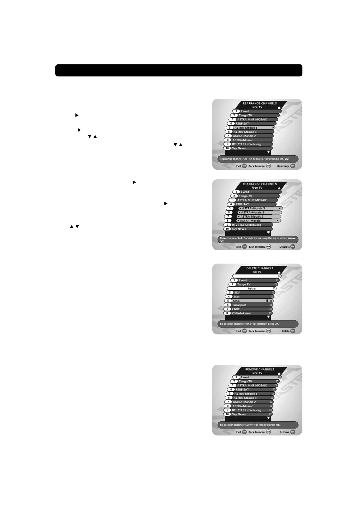
MAIN MENU
Rearrange channels
From here you can arrange the sequence for the channels within
your favourite lists.
• With
• Press
• Move the channel to the desired position with and press
It is also possible to first mark several channels, and then move
them all simultaneously.
• For each channel, press the
• When a number of channels are marked this way and you want
• The marked channels will now be put together into one group.
• The right side of the first and last marked channel will change
• Use the corresponding buttons to move the selected channels
• When the channels are in the position you want, press OK.
, mark the channel you want to move to a new posi-
tion within the list.
again and the right side of the marked channel will
change to .
OK.
button to add it to the set of
marked channels.
to move the whole set of channels, press again.
to
arrows respectively.
to a new position within the list.
Delete channels
From here, when the “All TV” list is selected in the “Edit channels” menu, you can delete channels.
Please note. Channels deleted this way will be permanently
deleted. The only way to get them back is to perform a new
channel search.
To delete channels:
• Mark the channel or channels you want to delete by selecting
the channel and pressing OK.
• Press BACK to delete the selected channels.
You will be asked if you really want to delete it. If so, confirm by
pressing OK once more. If not, press BACK.
Remove channels
From here, when the “Free TV” or a favourite list is selected
in the “Edit channels” menu, you can remove channels from
those lists.
To remove channels:
• Mark the channel or channels you want to remove by select-
ing the channel and pressing OK.
• Press BACK to remove the selected channels.
You will be asked if you really want to remove it. If so, confirm
by pressing OK once more. If not, press BACK.
Channels removed from a list this way are not permanently deleted. They are still available from the “All TV” list.
GB 43
Page 44

MAIN MENU
Update channels
When new TV and radio channels are added to the different satellites, you can check and automatically update the channel lists.
New channels will be marked with a star
After each download, check the channel lists for new channels
marked with
During the search procedure the old channels will be coloured
light blue, and new channels found will be coloured black in the
“Channel search progress” menu.
The following alternatives are selectable:
1 All configured satellites: Will search and update the lists from
those satellites you use to watch channels from. If you, for
example, have downloaded channels from ASTRA, THOR and
SIRIUS, those three satellites will be updated.
Note: This alternative is only possible for fixed antennas. If
your antenna is controled by motor, the first line will not be
selectable.
2 Current satellite: Will search and update the lists from the
satellite you right now are watching TV.
3 Current network: Will search and update the lists from the
network the present channel belongs to.
4 Current transponder: Will search and update the lists from
the transponder the present channel belongs to.
.
in the channel lists.
You can find out which satellite and network the channel you are
watching right now belongs to:
While watching a channel, first press OK, then the “i” button.
Update channels via a PC
It is also possible to update new channels via internet and a PC.
You will find information how this is done on the URL
http://www.lyngsat.com/nokia
GB 44
Page 45

MAIN MENU
System configuration
You will be asked to enter your access code before you can enter this menu. The code is preset to 1234 from the factory.
(The code can be changed from the Parental control menu. Refer to page 50.)
If you want to customize the system to suit you better, you can
specify some settings from the submenus in the “System configuration” menu.
Please note that many of these functions are the same as in the
“First time installation.”
Channel search
The procedure is the same as performed during the First Time Installation. Please refer to page 18-19.
Edit satellites
When a new satellite has been sent into orbit, or if you select a
not preprogrammed satellite, you can add it to the existing satellite list.
To add a new satellite
• Select the line “New satellite”.
• Press OK.
• Enter the name of the new satellite. (How to enter a name is
described on page 41.)
• Enter the position (in degrees) with the numeric buttons on the
remote control. (Use the left arrow button to erase digits.)
• Select orientation; East or West.
• Press OK to save these settings.
Before you can watch channels from that new satellite you must
also carry out the following steps:
For a fixed antenna:
• Select “Antenna/Satellite configuration” in the “System con-
figuration” menu.
• Follow the instructions on page 15. From the menu “Antenna
adjustment” select the new satellite name.
GB 45
Page 46

MAIN MENU
• Adjust the antenna towards the new satellite. Look at the Sig-
nal strength (AGC) and Signal quality (SNR) bar indications to
check the levels. Please note: In this case, (a brand-new satellite), you do not get a TV picture in the background on the
screen, even when the SNR indication is good! When both
indication bars (AGC and SNR) are good:
• Press the BACK button until you return to the ”System con-
figuration” menu.
• Select ”Channel search”.
• Select “Manual” or “Advanced” search.
• Select the new satellite name.
• Enter the settings for Transponder frequency, Polarization etc.
for the new satellite.
• Press OK to start the channel search procedure in order to
download channels from the new satellite.
• When you get the message on the screen that ”you have
found X new TV-channels and X new radio channels”, press
OK to save the new channels.
The new channels will be saved in the channel list they belong
to.
At the same time as you save the new channels, also the settings
for the new satellite will be saved.
When your antenna is controlled by a motor:
• Enter the “Channel search” menu.
• Select “Manual” or “Advanced” search.
• Select the new satellite name.
• Enter the settings for Transponder frequency, Polarization etc.
for the new satellite.
• Select the last line, “Adjust motor”, from where you now, by
pressing the
tenna to the position for the new satellite.
Look at the Signal strength (AGC) and Signal quality (SNR) bar
indications to check the levels. Please note: In this case, (a
brand-new satellite), you do not get a TV picture in the background on the screen, even when the SNR indication is good!
When both indication bars (AGC and SNR) are good:
• Press OK to start the channel search procedure in order to
download channels from the new satellite.
• When you get the message on the screen that ”you have
found X new TV-channels and X new radio channels”, press
OK to save the new channels.
The new channels will be saved in the channel list they belong
to.
The position of the new satellite will be added to the preprogrammed satellite positions in the antenna motor.
buttons on the remote control, can
move the an-
GB 46
Page 47

MAIN MENU
View attributes
Chech position and orientation for different satellites by selecting the line “View attributes”.
Delete satellite
You can also delete an added satellite. (This is not possible for the
factory preprogrammed satellites.)
If you want to delete the satellite from which you right now are
watching a channel, you will get a screen message about how
to proceed.
When you delete a satellite you also delete its channels from the
channel lists.
Antenna/Satellite configuration
Set up and adjust motor
The procedure is the same as performed during the First Time Installation. Please refer to page 16.
East/West limit setup
You only have to set one or both of these limits if the antenna is
prevented from reaching its East/West limit positions. This could
be the case e.g. if the antenna is mounted to close to a wall or in
any similar situation.
• To set these limits, select East or West limit setup and press
OK.
• Adjust the antenna using the
Watch the antenna movement, and when it has reached its possible limit, press OK. The other limit is set in the same way (if
needed).
buttons.
Remove limits
In case you need to remove limits.
When you perform this command you do not just remove the lim-
its. The motor will also turn itself to the 0° (Zero) position. How-
ever, next time you select a channel the motor will turn to its
proper position.
TV settings
From here you can adjust settings concerning your TV.
TV screen format
Select your TV screen format.
The 4:3 format is the standard format for most TV screens.
Select 16:9 for a wide screen TV.
GB 47
Page 48
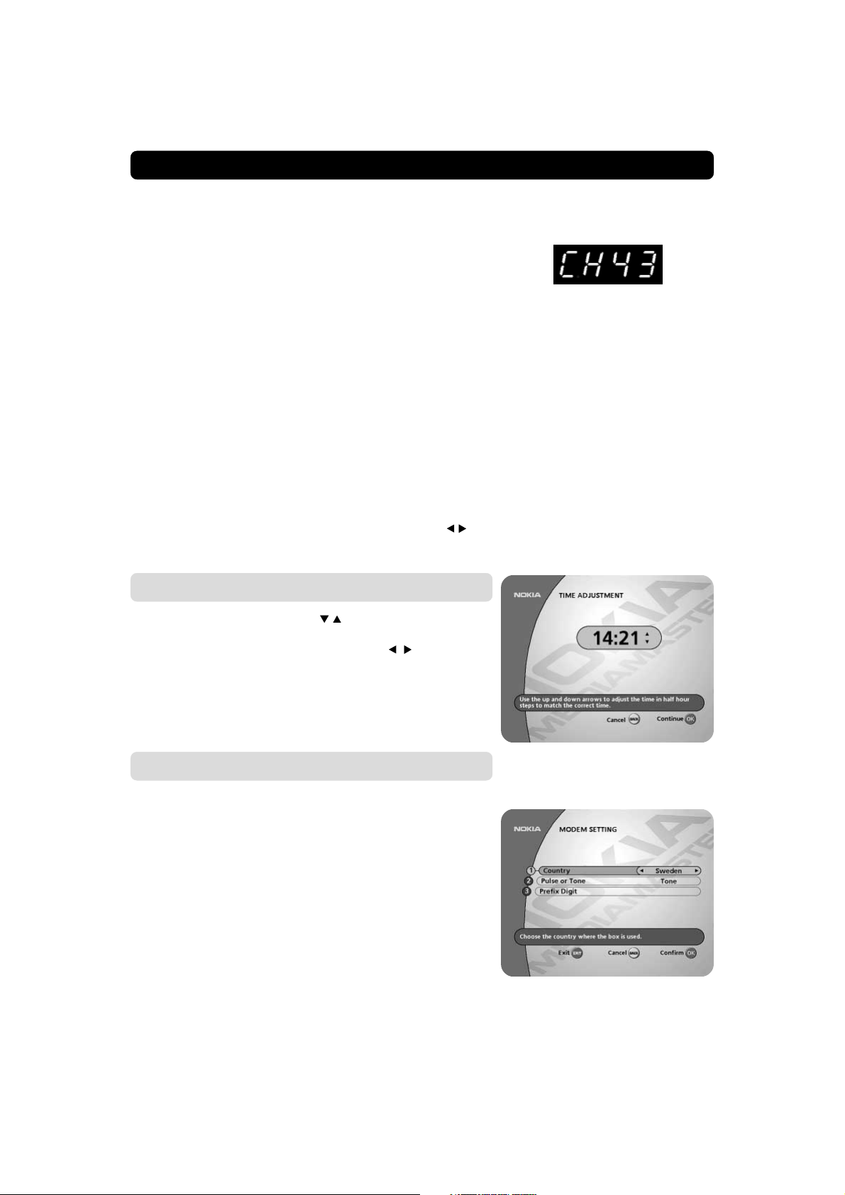
MAIN MENU
TV signal
If the teletext function does not work when watching channels
from an analogue satellite receiver connected to the Mediamaster, change this setting from RGB to PAL.
RF channel
Select this alternative if you have to change the RF channel.
If you change the RF channel number, you must also change it
to the same value on the TV. If you do not, the picture will become
black.
RF modulator type
If the Mediamaster is connected to the TV by an RF cable, you
can select the RF modulator type. The RF modulator affects a
channel’s audio. If you get picture but no sound, the RF modulator selection might be wrong.
Select “Normal (PAL B/G)” for all countries except the UK.
Select “UK (PAL I)” when the box is used in the UK.
Position of the RGB output
Adjust the horizontal position of the TV picture with the
tons. (The “TV signal,” see above, must be set to RGB for this
function to work.)
but-
The RF channel number will be indicated on the front display of the
Mediamaster.
Time adjustment
The time is adjusted by using the buttons, ±1/2 an hour at a
time.
You can also adjust the minutes by using the buttons.
Modem Setting
The modem function is only valid in Scandinavia.
The Mediamaster is equipped with a built in telephone modem.
Via the modem so called “interactive services”, such as e.g. ordering movies, can be performed.
You will get more information concerning this service by your
service provider. More information may also be available in the
“System information” menu, ref. to page 54.
When configurating the modem, the following parameters have
to be set.
Country: Select the country where the box is installed.
Pulse or tone: Select the alternative valid for your system. If in
doubt, please contakt your phone operator.
Prefix: If the connection has to pass a switch board, enter the
figure that will open the line.
GB 48
Page 49

MAIN MENU
Information about the modem
This equipment has been approved pursuant to Council Decision
98/482/EC [CTR 21] for pan-European single terminal connection
to the Public Switched telephone Network (PSTN). However, due
to differences between the individual PSTNs provided in different countries, the approval does not, of itself, give an unconditional assurance of successful operation on every PSTN termination point.
In the event of problems, you sholud contact your equipment
supplier in the first instance.
Erase hard disk
When you feel that the hard disk is a bit too cluttered, a good
advice is to clean it up totally. Select “Erase hard disk” and everything on it will be wiped out.
Receiver upgrade
In order to keep the Mediamaster up-to-date, it will be possible
to download new versions of the system software via satellite
and from the Internet. New software may include new or improved features for existing menus.
Enter this menu to check for new software. If new software is
available you will get information in the menu on how to proceed.
If you download new software from ”Nokia Internet pages”, you
transfer the software from the computer to the Mediamaster via
the serial port.
IMPORTANT! Updating via satellite may take a while. The front
display will indicate the percent left to download.
NEVER turn off the Mediamaster, never use the remote control or disconnect the antenna/LNB cable during the download procedure! This will damage the software and the receiver will have to be sent in for service!
Reinstall
Use this option only if you have to start the complete installation
procedure from scratch. If you continue from here, all your previous settings, parental code and favourite channels etc. will be
erased!
If you do not want to perform a reinstallation you can leave
this menu when the warning is displayed by pressing BACK.
GB 49
Page 50
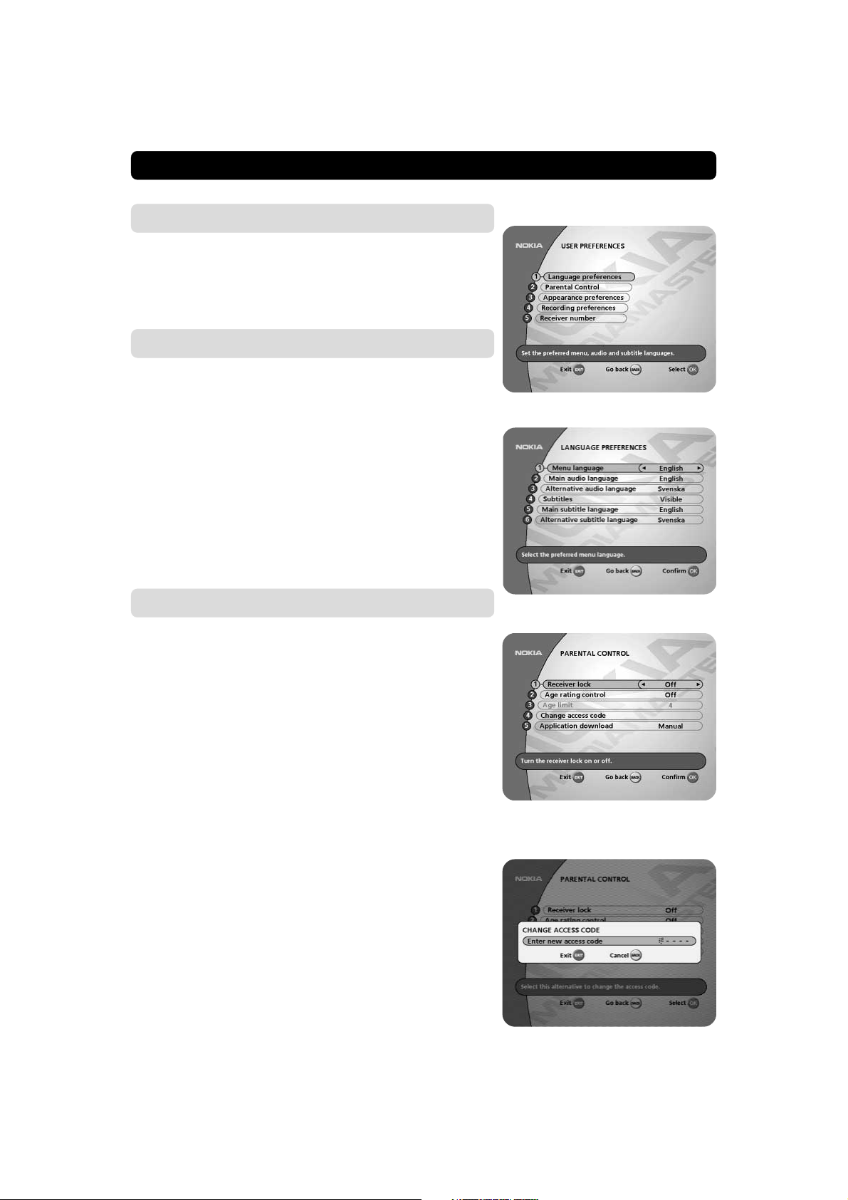
MAIN MENU
User preferences
From here you can change the menu language. You also have
access to the Parental Control, the Appearance and Recording
Preferences menus.
Language preferences
Menu language
Here you may select in which language the menus will be shown .
Main and alternative audio Ianguage
If more than one audio language is transmitted, you may select
the main and an alternative language.
Subtitles
If you select the “Visible” alternative for subtitling and more than
one language is available, you may select a main language and
an alternative.
In case you want to control the Teletext function with your TV
remote control, this parameter must be set to ”Invisible”.
Parental control
To open this menu you will be asked to enter your access code.
From the factory the access code is set to 1234.
The following settings can be altered from this menu.
Receiver lock
If you select “On,” you will have to enter the access code every
time you start the Mediamaster from standby.
Age rating control
If you want everybody to have access to all available types of programmes, select “Off.”
If you select “On,” you may block programmes unsuitable for
children. Select an age limit between 4 and 18 years on the line
that appears.
However, you should be aware that not all Service Providers have
the necessary codes for these functions implemented in their
transmissions.
Do not use this Age rating control function if you are using the
Age rating control provided with your Smartcard. See page 56.
Change access code
From here you can change the access code from the standard 1234. DO NOT FORGET IT! Without it you do not have access to any of the functions where the code is required!
If you forget it, you have to contact an Authorized Nokia
Service Center to get help.
GB 50
Page 51

MAIN MENU
Application download (“Open TV” applications)
From some channels it is possible to download specific programme applications such as games and various information.
When you select the alternative ”Manual” below, channels which
provide these services will show a symbol in the upper left corner of the screen. By pressing the red button on the remote control you start the download of the application.
Manual: You select to download the application manually. A Symbol will be shown on the screen.
Automatic: When you select a channel containing a
downloadable application, it will automatically be downloaded
when you select the channel.
Off: It will not be possible to download applications. No symbol
will be shown on the screen.
Symbol on screen
To close an application and return to watch TV, press the P+ or
P- button on the remote control.
Appearance preferences
Banner time-out
When you switch channels, an information banner will be shown
for a few seconds. You can select for how long the banner will
be shown.
Volume bar
Select whether or not you want the volume bar to appear on the
screen when you change the volume.
Volume bar time-out
Select how long the banner will be visible on the screen.
Subtitles
Select whether or not subtitles will be visible on the screen.
In case you want to control the Teletext function with your TV remote control, this parameter must be set to ”Invisible”.
During an application download
the picture above will be shown
on the TV screen
Picture format
If you have a TV set with the 4:3 picture format and the transmission is in 16:9, you can select Fullscreen or Letterbox.
Fullscreen will fill up the screen but cut off some information on
the left and right sides.
Letterbox will give a complete picture, but leave black areas at
the top and bottom.
‘letterbox’‘fullscreen’
GB 51
Page 52

MAIN MENU
Recording preferences
Changes made here will be the new default settings and will affect recordings made to the disk.
Make new recordings
The settings made here will affect Normal and Timer recordings
only. Pause recordings are always erasable.
Recordings with the Erasable property will automatically be
erased in order to make space for new recordings. Refer to line
6, “Erase before record (hours)”.
If you select Permanent you can only erase recordings manually.
This means, that if you fill up the disk with Permanent recordings, no new recordings can be made until you clean the disk from
at least some of them. This could mean the difference between
success and disaster when you e.g. make a Timer recording.
The default and also recommended setting is Erasable.
Saved pause recordings
If you select e.g. 10, there will never be more than 10 pause recordings stored at the same time on the disk. For every new
pause recording you make, the oldest of them will automatically
be erased.
Please note, that this will only affect pause recordings, not the
“normal” recordings. Pause recordings have the word Pause as
an extension at the end of the line in the “List of recordings”.
See the figure to the right.
Subtitles
Select “Yes ” if you want the subtitles in e.g. a movie to be recorded, or “No” if not.
Repeat playing
Normally you would want a playback to stop when it has reached
its end. If so, select “No”.
If you want the playback to automatically restart every time the
end is reached, select “Yes”.
Stop recording
While a Pause recording (not a normal recording) is still in
progress you can start the playback of it (= start watching it). In
the playback mode it is possible to use the “fast forward” function in order to catch up the live part of the programme.
When you do that, and you reach the end of the recording, one
of the two following things will occur.
• If you select “Yes”, which is the default setting, on line 5, :
When the end of the recording is reached by “fast forward” ,
the recording will automatically stop and the live programme
will be shown.
GB 52
Page 53

MAIN MENU
• If you select “No” on line 5:
A few seconds before the live programme is caught up, the
“fast forward” will slow down to normal speed. Due to the
fact that the recording is still going on, you will now still be
watching the recorded programme, but with just a few seconds delay from the live version.
However, in this situation you can stop the recording manually to watch the programme live instead.
Erase before record (hours)
Select how many hours you want to be automatically erased
from the disk each time a new recording is about to start. Only
erasable recordings will be deleted.
When you get a message saying that it is not possible to erase
the requested time, it is high time to clean up the disk.
Note, that the settings here are highly associated with the following subject, about Type of programme.
Type of programme
Different types of programmes will take up more or less space
on the disk when they are recorded. A recording of e.g. a pop
programme where one billion different colours will explode on
the screen each and every second (or any other programme with
high activity) will take considerable more disk space than e.g. the
latest news read to you aloud from the local TV studio.
Be aware that settings made in this menu has nothing to
do with, and does not affect, the recording quality.
High does not mean that the recording quality is set to high and
Low is not the same as low recording quality.
You must rather look upon this function as an assistance for the
box to estimate the free recording space (in hours) available on
the disk. This estimated time will be shown as “Time available”
in the “List of recordings”. The function also affects the previous subject “Erase before record (hours)”.
The four alternatives are:
High: For programme types with very high activity contents.
Normal: This corresponds to most programme types. It is there-
fore the default setting.
Low: For programme types such as news broadcast and
similar.
Radio: For recording of programmes when the box is in Ra-
dio mode.
It is not necessary to make changes in this menu every time you
are going to make a recording.
You should select one of the alternatives that corresponds to the
type of recordings you most frequently make.
As long as you always keep the disk almost clean, settings in
this menu are less important. But as the disk is running out of
space the settings will be more and more important.
GB 53
Page 54

MAIN MENU
The following extreme example
will show what might happen when the setting does not correspond with the reality, and the disk is getting filled up.
You are going to visit a concert, but do not want to miss the football championship that will be shown during your visit. You intend
to watch it when you come back home.
A Timer recording is perfect in this case. You are as usual in a hurry
and just throw an eye at “Time available” in the “List of Recordings “. It will let you know that “Approx. 3 hours” are available.
Good! More than enough.
As soon as you return back home you start the playback and everything is OK in 6 minutes and 12 seconds. That is when the playback ends. We will skip your comments and instead find out what
went wrong.
As you are a music lover and often record music, the setting in
this case was Radio. It should have been set to High instead.
Conclusion: Keep the disk clean and pay some attention to settings from this menu.
Receiver number
If you have more than one digital satellite receiver using the same
IR protocoll, you can use the same remote control to control
them. To do that you have to give each receiver a specific number.
There are four numbers to choose from.
To access a specific receiver, press
trol simultaneously, where X is the number you have chosen for
the specific receiver.
X on your remote con-
System information
If you have to contact your service provider or a service center,
they might ask for information available from this menu. Therefore, it is important that you first check the information in the
following menus.
System information
This gives general information about which hardware and software version your Mediamaster is running on.
GB 54
Page 55
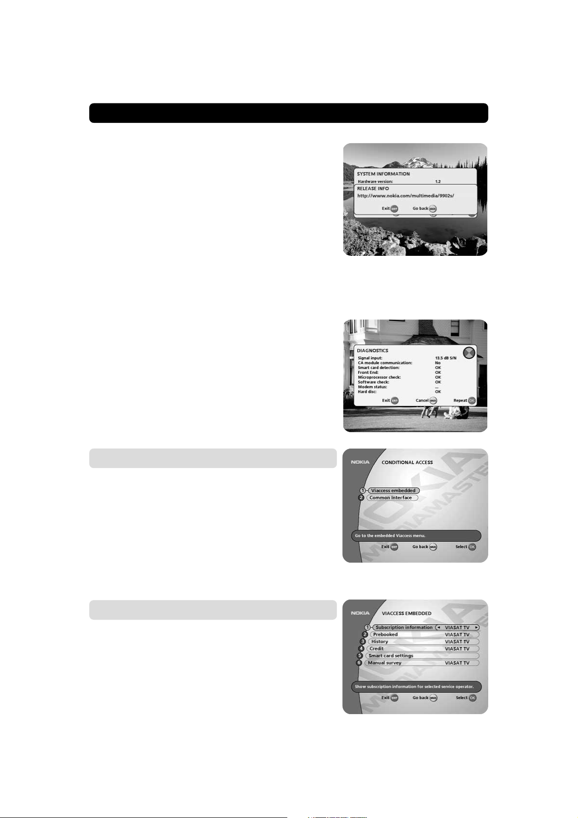
MAIN MENU
Release info
The alternative “Release info” will only be available when the
new downloaded software contains information.
If so, by pressing the i button you will get a message describing
the new functions in the latest software release you have
downloaded to the Mediamaster.
Diagnostics
To find out the condition of certain parts of the Mediamaster, you
can run a diagnostic test.
Conditional Access
This menu will only be activated if you have inserted a valid Smartcard in the slot behind the front lid.
If more than one CA system is activated, select the one from
which you want information.
The Viaccess Conditional Access (CA) System is embedded in the
Mediamaster. A Smartcard that supports this standard can be
used in the left slot on the front panel.
Different CA modules (with their Smartcards) supporting the DVB
Common Interface (CI) standard can be used in the right slot.
Viaccess embedded
From here you get subscription information from a Smartcard
supplied by a Viaccess Service Provider.
GB 55
Page 56

MAIN MENU
Smartcard settings
Age rating control
This is an age rating control function which is connected to your
smartcard. It will only affect the channels you have subscribed
to. Choose “On” if you want to activate the age rating.
This means that you have to enter your smartcard PIN code to
be able to watch the age rated channels. The age rating of each
programme is controlled by your Service Provider.
Do not use this Age rating control if you are using the Age rating control within the Parental control menu. See page 50.
Age limit
Select an age limit. Programmes transmitted with a lower limit
age will not need the access code.
Change Smartcard code
In this menu you can change the code on your Smartcard.
Common Interface (CI)
These menus are provided by the CA module and its Smartcard.
Timer
General
You can program the Mediamaster to start and stop at a
predefined time.
The function is very useful when you want to record a programme
and you are unable to start/stop the recording event yourself.
Or when you just want to be reminded of the start of a programme you do not want to miss.
A programme that already has been started by this Timer function will lock the box. The display on the box will indicate
“t x” (where x is the channel number) while you are watching
a programme you have been reminded to watch. During a digital
recording event the display will show “r E C”.
You can not change channels or call up a menu until the stop time
is reached. However, you can interrupt the event (e.g. stop a recording) by pressing the MENU button (about 5-10 seconds) until
a channel number appears in the display. Please note, that this
is the only way to stop a recording that has started (apart from
pulling the plug from the mains, which is not to recommend.)
GB 56
Page 57

MAIN MENU
Important information related to the timer recording
If you program the box to perform a timer recording e.g. in the
middle of the night (or at any other unsuitable time), be sure to
turn the TV set off with the mechanical switch located on the TV!
If you turn the TV set off by just putting it into standby mode with
the remote controll, it will be turned on at the time for the recording!
Timer setup
• Select Timer from the Main Menu.
• Press OK to enter the Timer Setup menu from where you
make the settings.
• First, select Channel List with the
• Then, step to Channel to select desired TV/Radio channel.
• The present date (month/day) will automatically be preset.
When you change month and day, always use two digits for
each of them.
• If you enter a wrong digit you can erase it with the
The different start times may never overlap each other. If you try
to enter a start or stop time within an already occupied period of
time you will get a warning message about it.
• On the last line you select the Action. When you want an
event to be recorded on the built in hard disk at the date and
time you entered, select Record. Events that you want to be
recorded this way will be marked with a red symbol in the
Timer list.
Do not forget to ensure that you have enough space on the
disk at the time for the recording to take place.
buttons.
button.
• If you just want to be reminded of a programme start,or when
you want to make a traditional analogue (VCR) recording, select View.
Up to 9 different events can be predefined. The events will be
sorted in start time order.
At each stop time the box will return to the state it had before it
started.
You can erase a predefined event by pressing the
(If you regret the command after the first press, go to another line
by pressing either
or and the event will not be erased.)
button twice.
Indicates a recording event
GB 57
Page 58

GLOSSARY OF TERMS
Access
Authorisation to use the coding system to purchase /
order TV programmes.
AGC
Automatic Gain Control.
CA
Conditional Access. A system to control subscriber access to services, programmes and events.
CA module
A device for the decoding of scrambled signals.
Common Interface
Describes a DVB standard hardware and software architecture for Conditional Access systems.
DVB
The Digital Video Broadcast group was created to establish a technical framework for the introduction of digital
video broadcasting systems.
EPG
Electronic Programme Guide. A software that enables
viewers to navigate easily among the large number of
channels provided by digital technology, in order to select the service they desire.
FEC
Forward Error Correction. Correction of faulty bits in the
received signal.
GHz
The prefix giga means billion, and Hertz means cycles per
second. Signals in the GHz range are often called microwaves.
LNB (low-noise block converter) or LNBF
An electronic unit mounted on the satellite dish. It receives the signals reflected by the dish and converts
them to signals that can be used by the Mediamaster.
L.O.
Local oscillator part of the LNB. It converts from the satellite frequency down to a frequency acceptable for the
Mediamaster.
Mediamaster
A unit that converts the digital satellite signals into audio
and video signals. The audio and video signal can be sent
to the TV set either via SCART or via RF (modulator output).
MHz
The prefix mega means million, and Hertz means cycles
per second.
MPEG
Moving Picture Experts Group. Established by the International Standards Organisation to provide the basis for
a picture coding and compression system.
Network
A number of digital channels transmitted from one
source. Grouped under separate headings in the channel
list.
Parental control
A feature that allows parents to ”lock” programmes that
they consider unsuitable for children. A ”locked” channel or programme can only be ”unlocked” with the special parental access code.
Parental Access code
A four-digit code stored in the Mediamaster. Used to
lock the Mediamaster.
PCMCIA
Personal Computer Memory Card International Association. The Common Interface slot follows this standard.
PCR
Program Clock Reference.
PIN code
Personal Identification Number. A four-digit code stored
in the Smartcard. For PPV (Pay Per View) or other services together with the subscription.
Polarization
Polarization allows several programmes to be fit into the
same frequency band. The signals from a satellite are
transmitted either with linear (vertical or horizontal) polarization or circular (right or left) polarization.
RF
Radio frequency (known as HF in some countries).
SERIAL RS 232
A serial communication standard data port.
SCART
A 21-pin connector used for connection of the
Mediamaster,VCR and TV. Also named Euroconnector
or Peritel connector.
Scrambled satellite TV programme
Some satellite TV programmes are transmitted in scrambled form. A Smartcard, and possibly a CA module, will
be needed to view such programmes.
Service provider
Is a company that collects a number of programms/services and distributes them to customers.
SNR
Signal to Noice Ratio. Signal quality measure.
S/PDIF
Sony/Philips digital interface format. Digital audio output.
Symbol rate
Speed of the digital transmission
SW
Software. Programme code.
Timer
A timer signals, starts or stops equipment at a preset
time.
TS
Transport stream.
VCR
Video Cassette Recorder.
GB 58
Page 59

PROBLEM SOLVING
Problem
The display on the front panel does
not light up/is not lit.
No sound or picture, but the front
panel shows the time or - - : - -.
No sound or picture.
No sound or picture on horizontal
modulated transponder.
Bad picture/blocking error.
There is no Welcome menu on the
screen after you switched on the
Mediamaster for the first time.
Possible causes
Mains cable is not connected.
The Mediamaster is in standby
mode.
The satellite dish is not pointing
at the satellite.
No signal or weak signal.
The LNB is faulty.
The satellite dish is not pointing
at the satellite.
Signal too strong.
Satellite dish is too small.
LNB noise factor too high.
The LNB is faulty.
The system is connected by SCART
cables and the TV is not in AV/EXT
mode.
What to do
Check that the mains cable is
plugged into the power socket.
Press the standby button or any
number button to bring the Mediamaster out of standby mode.
Adjust the dish. Check the signal
level indicator in one of the channel
search submenus.
Check the cable connections, LNB
and other equipment connected between the LNB and the receiver, or
adjust the dish.
Replace the LNB.
Increase the LNB voltage with 0,5 V
from the System Configuration
menu if you have a long cable.
Adjust the dish.
Connect a signal attenuator to the
LNB input.
Change to a larger dish.
Change to an LNB with lower noise
factor.
Change the LNB.
If the system is connected by
SCART cables, switch the TV to the
appropriate AV input.
There is interference on your digital
satellite channels, an existing terrestrial channel or video signal.
You made a video recording of a digital satellite channel and whole or
parts of the programme was not
recorded.
The system is connected by RF cables and the TV is not set to the
channel tuned for digital satellite
TV.
The system is connected by RF cables and the output channel of the
Media-master interferes with an
existing terrestrial channel or video
signal.
The Mediamaster was not left on
the appropriate channel.
The system is connected by SCART
cables and the VCR is not in AV/EXT
mode.
The system is connected by RF cables and the VCR is not set to the
channel tuned for digital satellite
TV.
If the system is connected by RF
cables, switch the TV to the channel for digital satellite TV. If you
have not tuned in the TV you may
do this first. Please look in the TV
manual for instructions. You can
also change the RF-channel in the
Mediamaster. See TV settings.
Change the Mediamaster output
channel to a more suitable channel
between 21-69, or connect the system by SCART cables.
If you make a recording of digital
satellite TV your Mediamaster has
to be left on the channel you want
to record.
If the system is connected by
SCART cables, switch the VCR to
appropriate AV input.
If the system is connected by RF
cables, switch the VCR to the channel for digital satellite TV. If you
have not tuned in the VCR you may
do this first. Please look in the VCR
manual for instructions.
GB 59
Page 60

PROBLEM SOLVING
Problem
The remote control is not working.
You see the on-screen message.
Viewing card error.
You have forgotten your secret PIN
code.
CA Module is not working.
Possible causes
Battery exhausted.
Remote control is incorrectly
aimed.
The Mediamaster is in standby
mode.
You have set a receiver number
and then changed batteries in the
remote control.
The Mediamaster can’t recognise
your Smartcard.
CA module is not installed.
CA module is not correctly
inserted.
What to do
Change the batteries (both).
Aim the remote control at box.
Check that nothing blocks the front
panel.
Check if (.) is flashing on the front
panel display when you press a button.
If not replace the batteries (both).
Press X on your remote control
simultaneously, where X is the
number you have chosen for the specific receiver. If you don´t remember
what number you have used, try 1-4.
Check that you are using the proper
Smartcard. Check that the Smartcard
has been correctly inserted with the
gold chip downwards. If the problem
persists, you may have a problem with
the card.
Contact your dealer or Service Provider.
Contact your Service Provider.
They will help you set it up again.
Check that the CA module has been
correctly inserted.
Contact your dealer or Service Provider.
Black picture.
CA module is inserted but not
working correctly.
Eject the CA module and reinsert it
again.
What to do if you can’t solve the problem
If you have tried all of the actions suggested above, without solving the problem, please contact your
dealer or Service Provider.
FRONT PANEL DISPLAY
GB 60
When power-up, boot version,
product family and system software
version is shown.
When starting from standby, product variant and system software
version is shown.
Remaining time in percent during
the download procedure.
The Mediamaster is in standby
mode, and current time is shown.
Channel number in TV mode.
Channel number in radio mode.
RF channel in tuning mode.
In TV mode.
In video mode.
When downloading new software
via the air.
When downloading new software
via the Serial RS232 socket.
Error messages. For service personnel
Lights when no signal is being received.
Flashes when pressing a button
on the remote control.
Page 61

TECHNICAL SPECIFICATIONS
Transmission standards
DVB, MPEG 2
LNB / Tuner input
Connector 1x F-type (LNB)
RF input frequency 950-2150 MHz
RF input power level -25 to -65 dBm
Supply voltage 13 /18 V ±5%
Max. current 500 mA, overload protected
Control voltage 22 kHz, 0,65 V
DiSEqC Tone burst A/B or
pp
Level 1.2
RF impedance 75 Ω
RF modulator
In/out connector IEC female / IEC male
Modulator frequency 470 to 862 MHz
Output level 70 ± 5dBV
Output channel 21-69
Preset channel 43
Output signal PAL B/G orPAL I
TV SCART
Video output 1 V
Audio output 0,5 V
RGB output Internal RGB or from
(±1 dB) / 75 Ω
pp
/ R
>10 kΩ
rms
L
AUX SCART
RGB bandwidth 5,8 MHz ±3 dB
Fast blanking output Internal or from
AUX SCART
Status output 0/6/12 V / R
10 kΩ
L
AUX SCART
Video output 1 V
Video input 1 V
Audio output 0,5 V
Audio input 0,5 Vrms / R
Status input 0/6/12 V / R
Fast blanking input 0/2 V for RGB, bypass to
(±1 dB) / 75 Ω
pp
/ 75 Ω
pp
/ R
>10 kΩ
rms
L
>10 kΩ
L
>10 kΩ
L
TV SCART
RGB input Yes
DIGITAL AUDIO (S/PDIF)
Connector 1 x RCA
AUDIO R L
Connector 2 x RCA (R+L)
Output 0,5 V
± 0,5 dB/ RL 10 kΩ
rms
SERIAL (RS 232) serial data
Connector 9-pin D-sub male
Signals RS232, max. 57600 bit/s
Pin 1 DCD (Data carrier detect) not
connected
2 RXD (Receive data)
3 TXD (Transmit data)
4 DTR (Data terminal ready) Set to high
5 GND (Signal ground)
6 DSR (Data set ready) not connected
7 RTS (Ready to send)
8 CTS (Clear to send)
9 RI (Ring indicator) not connected
Telephone (return channel on the phone line)
Contact modular 6-pin jack
Protocol V22, 1200 bits/sec
Security information
The modem connection is made according to the TNV 3 circuit
type. All other connections are made according to the SELV
circuit type.
Conditional Access system
Embedded Viaccess. One PCMCIA interface for a Common
Interface CA module (DVB Standard)
Smartcard Interface
Interface for one card according to ISO 7816
Supports embedded Viaccess descrambler.
Front panel
4x7 segment numeric LED display, Buttons: ,
(standby, progr. number up and down)
Other data
The model code, variant and serial number, are located on a
label on the underside of the housing.
Hard disk 40 Gigabyte
Supply voltage 95-250 V AC, 50-60 Hz
Power consumption max 27 W at 500 mA LNB load
Power consumption in
standby 7,5 W
Operating temperature +5° C to +40° C
Storage temperature - 40° C to +65° C
Humidity 25 to 90 % rel humidity
Operating distance for
remote control max 10 meters
Dimensions (w x d x h) 380 x 240 x 69 mm
Weight 2,4 kg approx
SCART sockets
TV AUX
1 Audio out right ch. Audio out right ch.
2 - Audio in right ch.
3 Audio out left ch. Audio out left ch.
4 Audio ground Audio ground
5 RGB blue ground RGB blue ground
6 - Audio in left ch.
7 RGB blue signal out RGB blue signal in
8 Switch voltage out Switch voltage in
9 RGB green ground RGB green ground
10 Connect to pin 10 in AUX scart
11 RGB green signal out RGB green signal in
12 - 13 RGB red ground RGB red ground
14 Fast blank. ground Fast blank. ground
15 RGB red signal out RGB red signal in
16 Fast blanking out Fast blanking in
17 Video out ground Video out ground
18 - Video in ground
19 Video out Video out
20 - Video in
21 Ground (casing) Ground (casing)
220
121
GB 61
Page 62

Important Information
Wiring the plug (UK and Eire only)
The mains lead on this product is already fitted with a non-rewireable (moulded) plug incorporating a fuse, the value of which is indicated on the pin face of the plug.
Should the fuse need to be replaced, an ASTA or BSI approved BS 1362 of the same rating
fuse must be used. If the fuse cover is detachable, always refit the cover after replacing the
fuse.
NEVER use the plug with the fuse cover omitted. If the fitted plug is not suitable for your socket
outlets, it should be cut off, after having first removed the fuse, and an appropriate plug fitted
in its place. If this new plug contains a fuse, its value should be the same as that removed from
the non-rewireable plug.
The severed plug must be destroyed immediately to avoid possible shock hazard. If you need
to replace the mains plug, follow the instructions given below:
The wires in the mains lead are coloured in accordance with the following code:
BLUE - Neutral (N):
BROWN - Live (L). As these colours may not correspond with the coloured markings identifying the terminals in your plug, proceed as follows:
The wire coloured BLUE must be connected to the terminal marked with the letter N or coloured BLUE or BLACK.
The wire coloured BROWN must be connected to the terminal marked with the letter L or
coloured BROWN or RED. On no account should either of these wires be connected to the
terminal marked E or coloured GREEN or GREEN and YELLOW.
Before replacing the plug cover, make certain that the cord grip is clamped over the sheath of
the lead: not simply over the two wires.
If in doubt, consult a qualified electrician.
Nokia and Nokia Connecting People are registered trademarks of Nokia Corporation
www.nokia.com
66 76986-18
© 0226
 Loading...