

Page 1
Owner’s Manual
MEDIAMASTER
9650S
Page 2

MEDIAMASTER 9650S
Contents
FOR YOUR SAFETY 4
Rear panel
Front panel
INSTALLATION OF THE MEDI AMASTER 5
Connecting the Mediamaster to the
satellite dish 6
Connecting the Mediamaster to a TV set 6
Connecting to a TV and a video recorder 7
If your VCR does not have a SCART-
Connector 7
Connecting to an analogue satellitereceiver and a video recorder 7
Connecting to Hi Fi system 8
Preparing the remote control 8
Before you continue 8
About Smart Card and CA Module 9
REMOTE CONTROL 10
BASIC SETTINGS
Tuning procedure when RF
Connections are used
The Welcome Menu 12
Language settings 12
Antenna Satellite configuration 12
Automatic channel Search 13
Manual channel Search 14
VIEWING TV 14
General information 14
TV screen format 15
Start/stop watching TV 15
Select channel 15
Program Information, the “ i ” button 15
TV Guide 16
The Radio button 16
4
5
Nokia Home Communications operates a policy of continuous development.
Therefore we reserve th e right to make chan ges and improvements to any
of the products described in this manual without any prior notice.
The EMC Directive 89/336/EEC is applied to this product.
DiSEqC™ is a trademark of EUTELSAT
Nokia is a registered trademark of Nokia Corporation.
Copyright © 2000. Nokia Home Communications.
All rights reserved.
11
11
Volume level 16
List of TV channels 16
List of Radio channels 17
Video recorder 17
Subtitling and Teletext. The TEXT Button 17
SETTING FROM THE MAIN MENU 17
TV channels and radio channels 18
TV Guide and Radio Guide 18
Edit Channels 18
Rearrange List 19
Rename List 19
Add channels 19
Lock channels 19
Rearrange channels 20
Remove channels 20
USER PREFERENCES 20
Parental control 20
Language settings 21
System settings 21
On/Off Timer setting 22
GAME 22
INSTALLATION SUBMENUS 23
Antenna Satellite configuration 23
Automatic channel search 23
Manual channel search 23
Advanced channel search 23
Reinstall 24
System Information 24
CONDITIONAL ACCESS
GLOSSARY OF TERMS
PROBLEM SOLVING 26
TECHNICAL SPECIFICATION 27
M ENUS SCREEN STRUCTURE
25
24
28
GB 3
Page 3

FOR YOUR SAFETY
Keep a clear space around the Mediamaster to allow for sufficient ventilation.
Do not cover the Mediamaster or place it on a u nit that emits heat.
!"
Use a soft cloth and a mild solution of dish washing liquid to clean the casing.
!"
Never allow liquids, spray or other materials to come into contact with the inside of the
Mediamaster.
!"
Service should be carried out onl y at a Nokia authorized service center.
!"
Do not connect or modify cables when the Mediamaster is plugged in.
!"
Do not remove th e cover.
!"
Do not allow the unit to be ex p osed to hot, cold or humid conditions.
!"
Please note that the only w ay to isolate the Mediamaster completely from the 230 V mains supply
is to unplug the mains lead!
Rear panel
LNB input
Sate llite dish
input
(F-connector).
RS232
For a PC.
TV SCART
For the audio
/video input of the
TV set.
VIDEO OUTPUT
Composite video
signal output for a
TV set.
TV AERI AL
For a terrestrial
(conventional)
TV aer ia l.
AC INL ET
230 V AC
50 Hz
LNB output
Sate llite signal (IF) outp ut
with loop through. For
connecti on to t he other
sat e llite rec eiver if needed.
GB 4
MODEM
For conne ct i on
to an external
MODEM
VCR SCART
For conne ct i on t o a
VCR or an analogue
sat e llite rec eiver.
AUDIO L R
Stereo outputs for
connecti on to a HiFi
system.
TV/VCR
For an RF-Cable
to the aerial
input of the TV
or VCR.
Page 4

Front panel
INSTALLATION OF THE MEDIAMASTER
The box for your Mediamaster should contain the following items:
Mediamaster 9650S includes
Display
Shows channel number, remote control
signal and time in standby mode.
At start up, it displ ays the model number.
Power
To turn the receiver
on/off (standb y) .
Up/Down
Select channel number,
up/down.
Slot
For a two CA
Modu le With a
Smartcard
Pow er cable
About the SCART sockets
!"
The rear panel of the Mediamaster is equipped w ith 2
SCART
any o f these sockets, always use fully featured SCART
cables
SCART cables on the market and picture quality could be
reduced if you use them.
!"
SCART cables are also necessary to get stereo sound from a stereo TV and video recorder.
sockets.
(as supplied). There are “l ess w ell specified”
When you connect other products to
SCART Cable
Owner’s
Manual
Remote Con troller
and Batteries
GB 5
Page 5
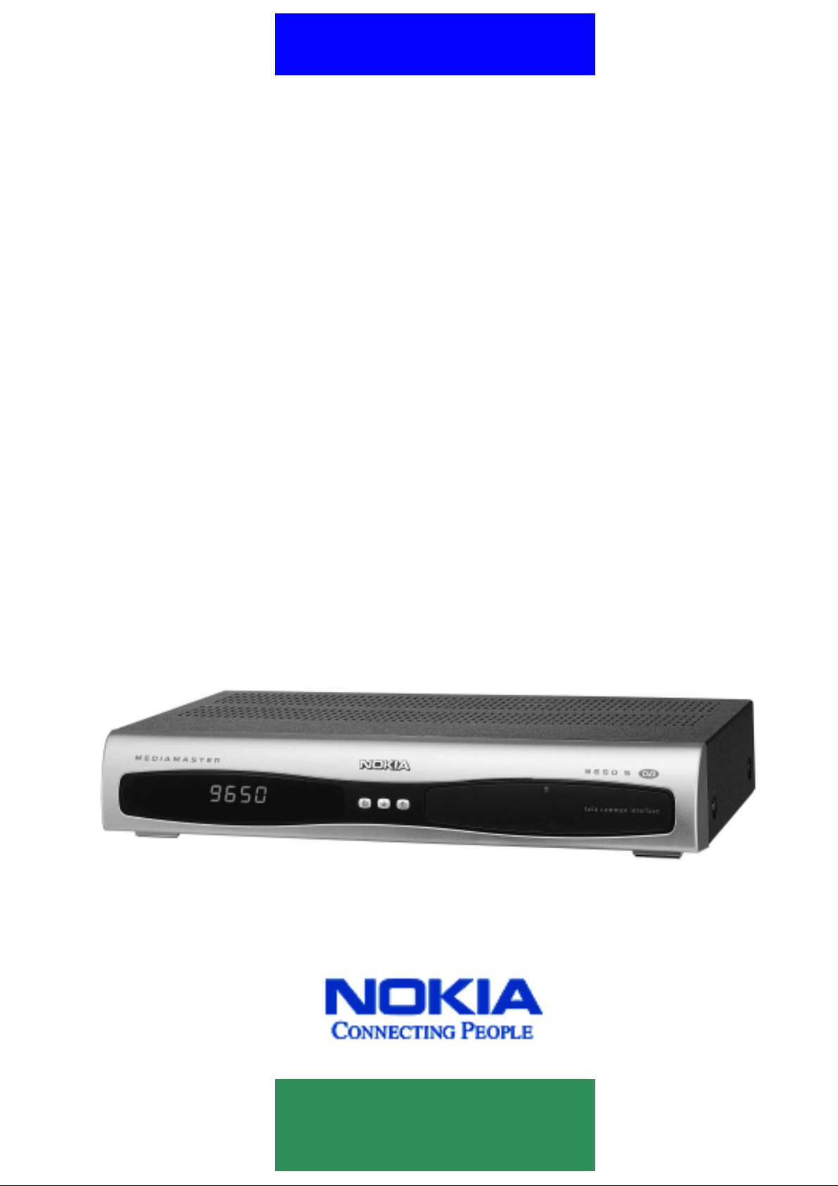
Connecting the Mediamaster to the satellite dish
Installing the satellite dish
!"
Your satell ite dish should be instal led with a cabl e for you to
conne ct to th e Mediamaster. If you do not have this cable you
will need to buy one from a dealer (tell the dealer you need a
coaxial cable and F-connectors).
!"
Connect the cable from the satellite dish to the socket
marked ”LNB IN” on the back of the Mediamaster.
If y ou need to fit the F-connectors onto the cable
15 mm
Prepare each end of the cable as shown in the diagram.
You will need to fold back the outer braid (as shown).
!"
Slide the F-connector onto the cable, and then turn it clockwise
until it grips the braid.
!"
Ensure that 3 mm of the core is protruding from the end of the
connector.
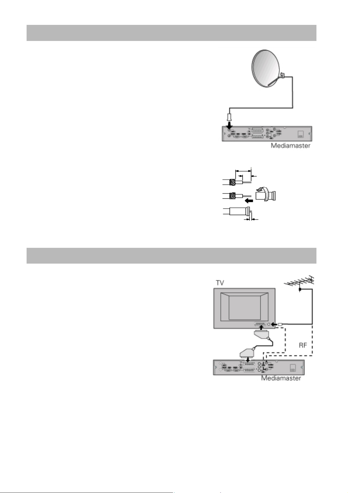
Connecting the Mediamaster to a TV set
There are many different types of TV/VCR and other
equ ipm e nt that you can connect to the Mediamaster. In this
manual you wil l see some of the most common ways to
connect your equipment. If you use RF cables you will have to
tune your TV and VCR to the Mediamaster outpu t channe l. If
you have problems with your connections and need help,
contact
!"
!"
!"
you r dealer or Service Provide.
Connect the SCART cable between the main SCART
socket on the TV and the TV SCART socket on the
Mediamaster.
Connect an RF cable from the TV/VCR output on th e
Mediamaster to the RF inp ut socke t on the TV.
Connect the TV aerial to the TV AERIAL inpu t socket on the Mediamaster.
8 mm
F-connector
3 mm
GB 6
Page 6
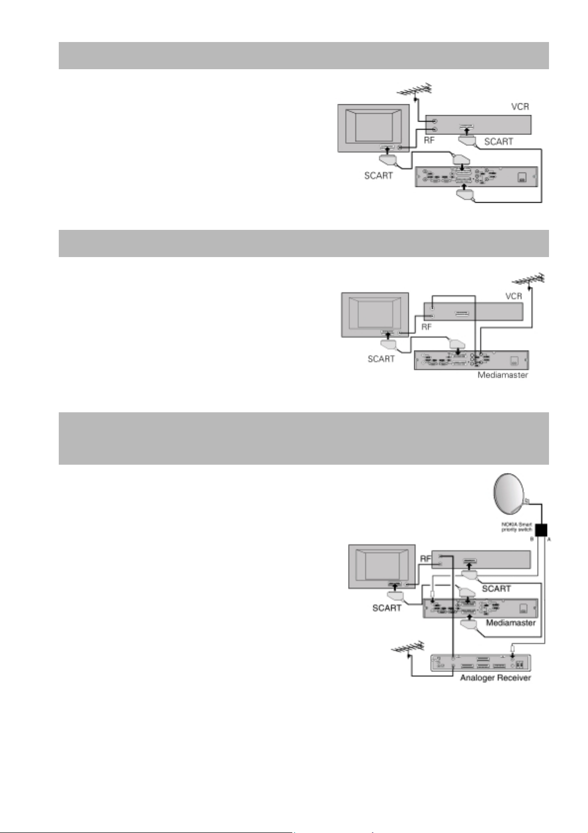
Connecting to a TV and a Video r ecor der
Refer to your video recorder manual for full instructions.
!"
Connect one SCART cable between the main
SCART socket on the TV and the TV SCART
socket on the Mediamaster.
!"
Connect another SCART cable between the VCR
and the VCR SCART socket on the Mediamaster.
!"
Connect the RF cable from the RF output on the
VCR to the TV aerial input on the TV.
!"
Connect the TV aerial to the RF input socket on the
VCR.
If Your VCR does not have a SCART connector
!"
Connect a SCART cable between the main SCART
socket on the TV and the TV SCART socket on the
Mediamaster.
!"
Connect an RF cable from the RF output on the
VCR to the TV aerial input on the TV.
!"
Connect an RF cable from the TV/VCR output on th e
Mediamaster to the RF input sock et on the VCR.
!"
Connect the TV aerial to the TV AERIAL input
socket on the Mediamaster.
Connecting to an Analogue satellite receiver and
a Vi deo recorder
!"
Connect a SCART cable between the main SCART
socket on the TV and the TV SCART socket on the
Mediamaster.
!"
Connect a SCART cable between the VCR and the
VCR SCART socket on the Mediamaster.
!"
Connect an RF cable from the RF output on the VCR
to the TV aerial inp ut on the TV.
!"
Connect an RF cable from the RF output on the
Analogue receiver to the RF input socket on the VCR.
!"
Connect the TV aerial to the RF input socket on the
Analogue receiver.
In order to switch the signal from the dish between
the analogue and digital receivers, you need a
Un iv ersal Twin LNB.
!"
Cable A between output A on the LNB to the LNB socket
!"
Cable B between output B on th e L NB to the ANTENNA socket
Bo th the VCR and the a nalo g ue sat e llite rec ei ver m ust be t uned to di f f erent UHF c hannels (t ha n the
Mediamaster) when using RF-connectors.
on the analogue receiver.
on the Mediamaster.
GB 7
Page 7
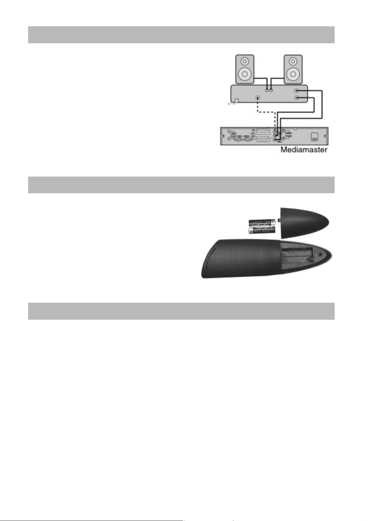
Connecting to Hi Fi system
Connect an RCA/Cinch stereo cable from the AUDIO L R
sockets on the Mediamaster to the LINE, AUX, SPARE or
EXTRA inpu t sockets on your Hi Fi system.
Preparing the remote control
!"
Remove the cover on the bat tery co mpartment at
the b ottom of th e remote control handset.
!"
Insert the 2 x AAA (1,5 V) batteries, as s hown in
the diagram, taking care to observe the + and
markin gs indicated inside.
!"
Replace the cover.
Before you continue
Please read this information concerning menus.
A menu is a f ield of text show n on the TV scree n. These menus contai n dif f erent ki nds of i nformati o n
and give t he possibility t o select be tween alte rnatives. A t the botto m of the scree n you wil l normal ly
also see a short expla nation of your options. A menu may contai n severa l li nes. Se lect ab le li nes ar e
highlighted. Non-h ighlighted lines are not selectable.
-
GB 8
Page 8
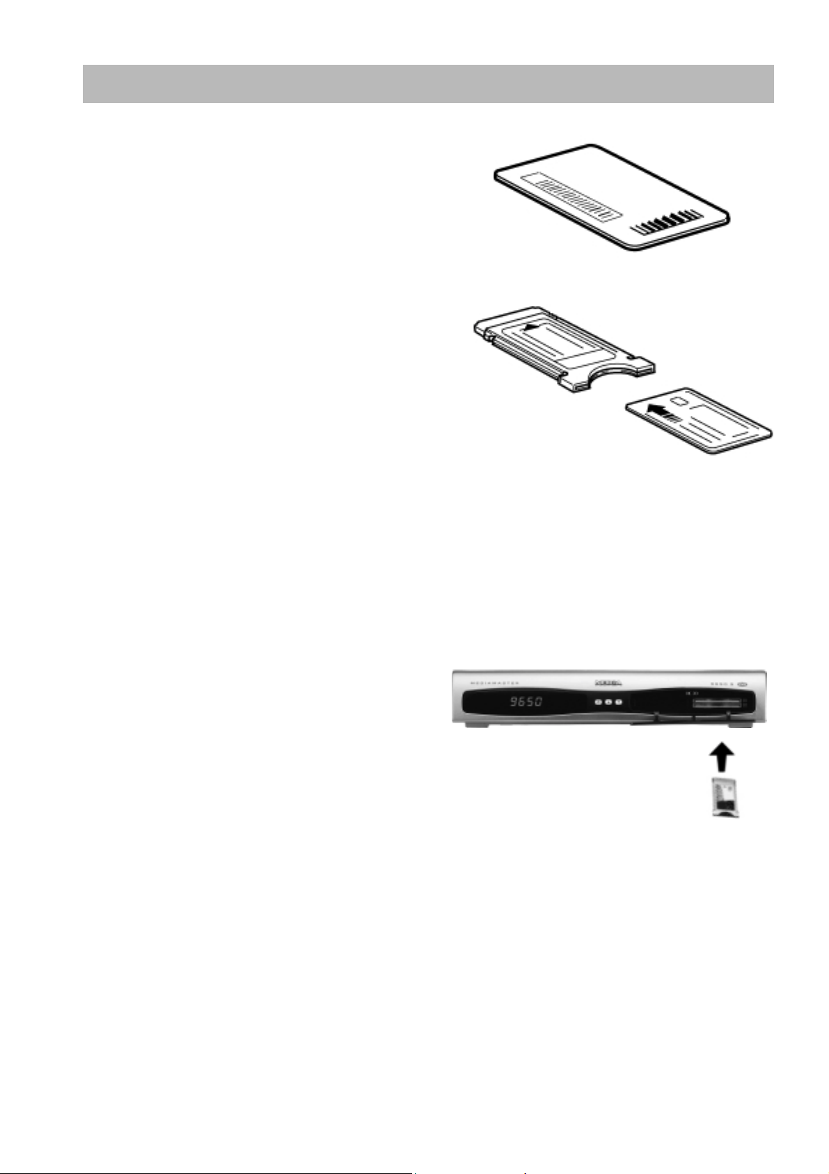
About the Smart Card and CA Module.
s
To be able to receive scrambled digital satellite
channels you will need a Common Interface CA
(Conditio nal Access) mod ule and a smartcard from a
Servic e Pro v ider. It is po s sible to use two CA modules.
The Service Provider is the programme distributor.
If you are subscribing to services from more than one
Service Provider, you migh t have to change between
different Smart-cards and/or CA modules.
Please note that a Smartcard and CA module may only
be valid for a single Service Provider and due to this, a
specific range of channels.
The Smartcard and the CA module may also provide
access to special menus not described in this manual.
If so, please follow the instructions from the Service
Provider.
Only ”free to air” channels are available without the Smartcard and/or the CA Modul e.
Note:
After inserting the card, leave it in the slot permanentl y. Do not remove it again, unless your Service
Provider asks you to do so.
This is important, because if your Service Provider wants to download new information to the
Smartcard, the card has to be in the sl ot.
The Smartcard and/or the CA modu le are distributed by your Service Provider.
The CA module with Smartcard
• Follow the ins truc tions from your Service Provider
concerning the Smartcard and/or CA Module.
• Insert the CA Module (use only a DVB Standard,
Common Interface CA Module) fully into the slot
behind the lid of the front panel of the Mediamaster.
• Press the gray button on the front panel if you
need to remove the CA Module.
Note !
Follow your Service Provider
GB 9
Page 9

REMOTE CONTROL
This section describes how to operate the Mediamaster using the buttons on the remote control.
Some of the functions can also be carried out using the buttons on the front panel .
To switch the Mediamaster in and out of standby mode.
EXIT TV
To switch between TV or Radio (in viewing mode).
0 – 9
Note:If 0 is entered as the first digit, the TV Release functionality is activated (see below)
0
TV Release. To switch between digital TV/Radio, analogue TV and analogue satell ite TV
BACK
TEXT
MENU
To return to the viewing mode from a menu without storing settings
(in menu mode).
To turn the sound off/on (mute).
To adjust the volume of digital programmes.
The Mediamaster’s maximum level is controlled by the TV’s present volume setting.
To change channel an d to select individual menu options.
and VCR, when your systems are connected by SCART
cables.
Info. To display short and exten ded information (if
transmitted) about current and next programmes.
To go back on e level in the menus without storing settings.
To select teletext information. Press to enter Teletext
(if available).
To display or exit from the “Main Menu” screen.
GUIDE
available channels. This information is only shown if your
Service Provider transmits programme information
P+ P-
OK
OPTION
FREEZE
To obtain a list of present and following programmes for the
(EPG information).
To ch ange channels up and down by one unit.
To change page in a m enu/list/text if more than one page
is available. To browse through teletext h istory.
To move up/down in the menus an d to change channels.
To chan ge settings in menus
To confirm choices an d selection of a highl ighted item.
To display the TV/Radio channel list.
(Red) Reserved for future application.
(Green) To select service options in viewing mode.
(Yellow) To select the freeze function.
Press once to freeze the screen picture.
Press any other key to go to normal mode again.
(Blue) To toggle between presen t and previous TV/Radio channels
.
GB 10
Page 10

BASIC SETTINGS
On ce you ha ve correctly connected the Mediamaster, you also have to perfor m some “
Settings
Please note!
The
next step in the installation process. However, and this is important, often more than one val ue has to
be entered in a menu. First, perform all necessary settings on the different lines. Then, confirm them
all simultaneousl y by pressing OK.
You can always go back to the previous menu by pressing the
Use the buttons to move upwards and downwards from one line to another. Use to change settin gs.
You can also use the numeric buttons on the remote contr ol to select a line in a menu and to enter
numeric values.
Tuning procedure when RF connections are used
T his procedure is nece ssa r y only if your Mediam aste r is con nected to the T V with an RF cable.
To tune your TV to the RF signal you might also need your TV manual in addition to this manual. The
steps below explain wh at to do if you have been unable to use SCART cables in your connection.
!"
”. During this procedure, helpful information is displayed at the bottom of the menus.
OK
button always
confirms
a selection within these menus, and p ressing it will take you to the
BACK
button.
Plug in your Mediamaster.
Basic
Tuning your TV to the Mediamaster.
!"
Select a channel number on the TV that is not currently used for other TV channels.
!"
Follow the instructions in your TV manual to tune the TV chan nel selector to UHF chan nel 43 (this
is the Mediamaster’s factory preset UHF channel). If you are already using this channel, select
another non occupied UHF channel between 21to 69 on the TV.
!"
When you have correctly changed the UHF channel number you will see the “Welcome” menu on
the TV screen. If there is interference from other ch a nnels you will have to change the chosen
UHF channe l.
!"
Follow the instructions in your TV manual to store this UHF channel as the channel used by your
Mediamaster. You will have to select this channel when you want to watch digital TV/Radio
channels.
.”
OK
button on the Mediamaster’s remote control
System
!"
Once the welcome message is visible, press the
to start the installation procedure.
If for some reason you have to change the RF chan nel later, you can do this by usin g “
Settings
different UHF channel (between 21 to 69) than the Mediamaster.
You may now proceed to “
” menu further on in this manual. If you have a VCR connected it must be tuned to a
The Welcome Menu
GB 11
Page 11

The Welcome Menu
To instal l the Mediamaster properly you have to adjust a few
settings. You will always be guided by the information at the
bottom of the menus. When you have finished the final part of
the setu p procedure you can start watching TV channels and
listening to radio channels. Now you shou ld have the
“Welcome Menu” on the TV screen. Press the
proceed.
OK
button to
Language Settings
Select the menu language that you desire. This will define the
language sh own in the menus. This will al so be the main
language for all the other parts such as audio and subtitling
languages. Press the OK button to proceed.
Installation
#"
In order to configure your equipment (satellite dish an d LNB)
you will need to use the foll owing menus.
The LNB is the receiving unit, which is mounted on the satellite
dish. For the following setup p rocedure you have to know the
Local Oscillator (LO) frequency valid for you r LNB(s).
Antenna and Satellite Configuration
Highlight “
button. You can configure the antenna for each satellite from
this menu.
Antenna Alternative
Select an Antenna al ternative from “1 to 16”. Please note, that
the parameters in the menu are pre-programmed, but you can
change any of them to suit your combination.
GB 12
Antenna Satellite Configuration
:
” and press the OK
Page 12

Satellite name:
Switch Type:
There are in prin ciple two kinds of external DiSEqC switches on th e market at present. One for
connection of two LNBs. The other one for connection of up to 4 LNBs.
From here you can select a name for the configuration.
If you have the other switch, defined as DiSEqC, Level 1 or 2 on the mark et, sel ect “
or 4)
”, for each LNB connected to respective inputs on this sw itch.
LNB Type
Selection is possible for different kinds of LNBs. Select the frequency for th e LNB, which is valid for
your combination . You may also enter a value with the numbered buttons on the remote control . Th e
LNB alternatives are: “
10.050
“
If you have special LNB type, you should select “User Defin e” on this men u. And you can enter a new
LNB frequency in the followin g LNB Frequency menu.
LNB Frequency
You can enter a special LNB frequency, which is not presented in the LNB Type list as above.
22KHz Tone Switch
If you have connected to a Dual LNB or two antennas connected to a 22KHz tone switch box, set it to
Enable
“
When you ha ve finished th e settings in this menu, press the “OK” button to save the parameter.
Press
:
Universal
10.600
”, ”
” th e 2 2 KHz tone switch.
BACK
10.750
”, “
:
to continue with the channel search set-up
”, “
:
” (which is the most common ) , “
11.200
”, “
11.475
”.
5.150
”, “
9.750
DiSEq C 1, 2, (3
10.000
”, “
”,
(You can also recall this menu later. From the Main Menu; select “Installation” and then “ Antenna
Satellite Configuration”).
Automatic Channel Search
Highlight “
button on the remote control. Mediamaster has preprogrammed Antenna/Satellite parameters for
Arabsat, NileSat, PanAmsat 4, AsiaSat2, AsiaSat3
TurkSat1B, TurkSat1C, Thor
Antenna Alternative
corresponds to your a ntenna system.
Predefined Channel
Choose a channel from which you want to start the channel search. Normally, each of the preprogrammed channel s gives the same result.
Search Type
Select “
Automatic Channel Search
and
: Select the option , “1 to 16”, th a t
: Each antenna alternative has one or two pre-programmed channel parameters.
: Select “
All Channels
Free Channels
” in order to search a ll channels on the satellite.
Other1
” in order to search for free channels only.
” using the down arrow
Astra, HotBird
,
Other7
to
.
,
GB 13
Page 13

Manual Channel Search
You can use manual channel search if you want to add new
channels later. For example If you have a special anten na
configuration which is not assigned in the “
alternative
manual channel search
“
Manual Search you first need to enter some parameters for the
channel search to work. The information you need to enter in
this menu is available in magazines covering satellite TV
reception, on the Internet or from your Service Provider.
Antenna Alternative
you wants to use for th e search.
” menu, you can add new channels using the
” function. When you perform a
: Select Antenna Alternative “1 to 16” th a t corresponds to the a ntenna which
Antenna
Transponder Freq (MHz):
remote control. If you e nter the w rong num b e r, erase it with the left ar row button.
Polarization
Symbol Rate (Msym/S)
FEC
: Enter the appropriate Forward Error Correction (FEC) value or select “
Network Search: Select
transponders u sed by a specific Service Provider.
Yes
(“
” is the de fault setting). Select “No” to search only from
the transponder that you h ave entered on the line
Transponder Frequency
“
search through all transponders for a specific program
distributor).
By pressing the OK button you can now enter the channel
search men u where the Mediamaster starts to search for
channels from the satellite.
VIEWING TV
: Select polarization; “
Specify the frequency in GHz. using the numbered buttons on your
Horizontal
: Enter the rate with the
Yes
: “
” to search from all
”. (Useful if you do not want to
Vertical
” or “
numbered
”.
buttons.
Auto
”.
General Information
The following will describe the basic functions of your Mediamaster while watching TV or listening to
radio channels.
Sometimes the information may not be displayed as illustrated. Many of the functions
descri bed here are dependen t on the Service Provider and/or can o n ly be used if they are
included in the transmitted programme information.
Please note
available ch annels. This may inclu de channels from various Service Providers, also those to which
you normally do not have access. If you select a programme to which you do n ot have access, you
will get the message “Service is scrambled or not running” on the screen.
GB 14
that during the Channel Search procedure, the Mediamaster has downloaded ALL
Page 14

TV Screen Format
If you have a TV set with a 4:3 picture format, and the transmission is in 16:9, you can sel ect “
(Pan & Scan)
screen vertically, bu t cut off some information from the left and right sides of the picture. “
(Letterbox)
You can select the TV scre e n format in the “
preference
” will give a complete picture, but leave black areas at the top and bottom.
” menu.
4:3 (Letterbox)
” or “
” to change display format. “
System setting
” menu which is a subs idiary of the “
4:3 (Pan & Scan)
” will fill up the
4:3
4:3
User
Start /Stop Watching TV
To start the Mediamaster from stand-by mode, press th e “
on th e remote control. It is also possibl e to start b y pressing the button on the front of the
Mediamaster. Put the Mediamaster into stand-by by pressing again the “
In stan d-by mode the display wil l show the correct time. During viewing the channel number will also
be displayed.
Select Channel
Change channel with the numbered buttons or with the up /d own buttons on the remote control.
You can also use the buttons up/down on the front panel of the Mediamaster.
You can also select TV (Radio) channel in the TV (Radio) channel list. See the “
List of Radio Channel
and “
” of page 16 and 17.
Progr am Infor mation. T he “i” Button
” button or one of the numbered buttons
” button again.
List of TV Channel
”
Every time you change channel you will receive information for
4-5 seconds about the current programme. This information
includes: Channel number, n ame, programme title, and time for
present and following programmes. Press “
a channel. If your Service Provider transmits programme
information you will see: Correct time, a small amoun t of
information for the current and nex t programme, the name and
number of the channel, and finally the start and finish time for the programme.
If you w ant to get more detail ed information, press “
is shown. You will get extended information (if transmitted) about the current or next programme.
i
” while watching
i
” once more while the information box (banner)
GB 15
Page 15

TV Guide
By pressing the
TV Guide
the different channels. By pressing the
you also can also obtain information about the next programme.
The minimized viewing window al so helps you to select
channels and information. Use the
the cursor to different programme areas. You can obtain
extended information for a programme by pressing the “
GUIDE
which gives the titles of the current programmes on
button you obtain a ccess to the
LEFT
Up/Down
RIGHT
or
buttons to move
button
i
” button.
The Radio Button
The display on your Mediamaster and on th e TV screen will
show the name of the audio chan nel you are listening to. While
in audio mode, you can press the “i” button to get extended
information (if transmitted) about the audio programme.
Return to TV mode by pressing th e TV button again .
Volume Lev el
Increase or decrease the sound level by pressing the “
-
“
” buttons. A control bar will be displayed at the top of the
screen du ring level adj ustment. (The max. level for volume is
the current volume setting on the TV set). Please note, that the
volume adjustments also chan ge the volume level of to your
VCR during recording. It is possible to turn the sound on and
off with the button “ ”. Sound off is in d icated with the same
symbol on th e scre e n. If you turn the volume off with this button, it does not affect the volume of the
VCR during recordin g.
The current volume level will be remembered w hen you go to standby mode.
+
” and
List of TV Channels
While viewin g the TV you can see a programme list on the
screen by pressing th e OK button. You can chan ge to another
channel by pressing the
the OK button. To move faster (8 channels at a time) between
channels you can also use the
GB 16
UP/DOWN
buttons and then pressing
DOUBLE ARROW
buttons.
Page 16

List of Radio Channels
While l isten ing to radio Programmes you can see a programme
list on the screen by pressing the OK button. You can change
to another channel by pressing the
then pressing the OK button. To move faster (8 at the time)
between the channels you can al so use the
buttons.
Vi deo Recorder
With a Video Cassette Recorder (VCR) connected you can watch /record video tapes.
If your VCR is connected with a SCART cable and you press the start button on the VCR, the
playback will start and in terrupt the TV programme from the Mediamaster.
To watch TV programmes again, press the TV button or stop the VCR.
Please note, that during the recording of a programme,
registered! For ex ample: If you call up a Men u from the Mediamaster on the screen, the menu will
be recorded!
Subtitling and Teletext. The TEXT Button
Pressin g the
To enable the teletext display on the TV, press the
This is on ly possible if more than one subtitling language is being transmitted. Please refer to the
instruction ma nual of your TV for the teletext function. Exit the menu by pressing the TV button.
SETTING FROM THE MAIN MENU
Press the
TV screen. Press the
If you select one of the highlighted titles and press the OK
button, a su bmenu will be shown on the TV screen . F rom a
submenu you can adjust settings to your own requirements.
TEXT
MENU
button once while watching TV enables the te letext output to the TV.
button and you will get the Main Menu on the
EXIT
button to leave the menu.
UP/DOWN
DOUBLE ARROW
buttons and
everythi n g
Tel etext
shown on the screen will be
button on the TV’s re mote control.
GB 17
Page 17

TV Channels a nd Radio Channels
TV/Rad io Channels will show a list with the nam e s of the
different channels. To move faster within the list, use the
DOUBLE ARROW
channel.
buttons. Press OK to enter a marked
TV Guide and Radio Guide
These guides will give you an overview of programme
information from the TV/Radio chan nels. Step to different
channel numbers with the
highlighted l ine and press OK, you will exit the menu and enter
the highlighted chan nel. Select information about the
programme with the
extended information about a marked programme.
Please note,
in the transmission.
that information will only be shown if it is included
Edit Channels
From this menu, you can rename favorite lists, add channels,
remove channels and arrange the channels in a preferred
order.
All TV
The “
the channel search operation in the installation menu
The “
your own favorite lists you can make channel handling a bit
more convenient.
” list displays all chan nels, which you capt ured from
All TV
” list can contain hundreds of channels. By creating
UP/DOWN
RIGHT
buttons. If you stop on a
button. Use the “i” button to get
next
GB 18
Page 18

Rearrange List
If you have created several Favorite lists you can
determine the sequence in which the lists will appear. To
rearrange channels, select the list which you want to
move using the
position u sing the
OK
button.
UP/DOWN
Move the channels to the desired
button and press
OK.
Renam e List
You ca n change the list name with the virtual keyboard
on th e scre e n. Type in the text you want using the remote
control arrow keys. Please note that the “
Free TV
“
Delete the existing characters by pressing
key of the keyboard. Sel e ct the characters using the
RIGHT
To save the renamed list, press the
To select various characters, press
” and “
buttons. Press the
Add Channels
From here you can create your own favorite l ists, containing
th e channels you watch most frequently. You can g ive each list
a specific name in the “Rename List” menu. When a favorite
list is selected, you see only those channels defined in the list.
You can add channels to your Favorite Lists from the “All TV”,
“All Radio”, “Free TV” and “Free Radio” list. A channel is added
by pressing the OK button. The “V” marking to the right on a
line contains added channels.
Free Radio
All TV
” can not be changed.
OK
OK
button to enter the text selected.
BACK
OK
button.
on the page
All Radio
” , “
on th e
left
LEFT
UP/DOWN
” ,
arrow
and
box of the keyboard.
Lock Channels
To get to this menu you need an access code. The default
access code is “
unlock) channels in any of the lists in order to prevent e.g. your
children from watching. Select the channel you want to lock
and press th e OK button. A locked channel will be marked with
a padlock symbol. Repeat the procedure for each chann el you
want to lock. When you lock a channel in any list, the channe l
will automatically be locked in all other lists When watch ing TV,
you will be asked to enter your access code before you can
watch a locked channel.
1234
”. From here you can lock (and later
GB 19
Page 19

Rearra nge Channels
You ca n arrange the order of chan nels within your favorite lists.
To rearrange channels, select the channel which you want to
move using the
position using the
OK
button. Move th e channe ls to the d esired
UP/DOWN
button and press
OK.
Remove Channels
From her e , when the
Channels
Please note. Channels deleted this way will be
permanently remo ved. The only way to get them back is to
perform a new channel search.
To remove channels:
Select the channel that you want to delete an d press OK. You
will be asked if you really wan t to remove it. If so confirm by pressing
BACK.
USER PREFERENCES
From here you can change the menu language. You al so have access to the Parental Control and
the Appearance menus.
” menu, you can remove channels.
“All TV”
Parental Control
list is selected in the “
Edit
OK
once more. If not, press
By pressing
requested to enter your access code. (Personal Identification
Code).
This code is set to
menu from where you can lock some functions in the
Mediamaster.
Receiver lock
If you select “On”, you will have to enter the access code every
time you start the Mediamaster from stand-by.
Lock Installation Menu
If you select “On”, you will have to enter the access code every time you enter th e installation menu.
Age Limit
If you want everybody to have access t o all available t ypes of program mes, select “
If you select “On”, you may block programmes unsuitable for children. Select an age limit between 4
and 18 years on th e line th at appears.
However, you should be aware that not all Service Providers have the necessary codes for these
functions implemented in their transmissions.
GB 20
OK
on the line “Parental Control” you will be
1234
by the factory. You will then get the
Off
”.
Page 20

Change access code
From her e you can change the access code from the standard 1234.
DO NOT FORGET IT! Without it you do not have access to any of the functions where the code
is required!
If y ou forget it, you have to contact an Authorized Nokia Service Center to get help.
Language Settings
From here you can ch ange the language for the menus, main
audio language and altern ative audio language.
System Settings
From here you can adjust settings concerning your TV.
TV Screen Format:
The 4:3 format is the standard format for most TV screens.
Select 16:9 for a wide screen TV.
Select your TV screen format.
Output Selection:
watching channels from an ana logue satel lite re ceiver
connected to the Mediamaster, ch ange this setting from “
UHF Channel Number:
If you change the RF channel n umber, you must also change it to th e same value on the TV. If you
do not, the pictu r e will become black.
RF Modulator Type:
RF modulator type. Th e RF Modulator affects a channel’s audio. If you get picture but no sound, the
RF modulator selection might be wrong. Select “
Select “
Infor mation Box Timeout (secs):
for a few seconds. You can se lect for how long the banner will be shown
Display Volume Indicator:
when you change the volume
Date Setting (dd/mm/yyyy):
Time Setting:
GMT Offset:
Normal”
If the telete xt fu nction d oes not work when
Select this alternative if you have to change the RF channel.
If the Mediamaster is connected to the TV by an RF cable, you can select th e
UK (PAL I)
if it is used elsewhere.
Select whether or not you want the volume bar to appear on the screen
.
Used to set the current date, month and year.
Adjust the clock.
Adjust the time difference in you r countr y.
When you switch channel s, an information banner will be shown
RGB
” if the Mediamaster is used in the UK.
Composite”.
” to “
.
GB 21
Page 21

On/Off Timer Setting
You can enjoy this On/Off Timer for such a convenience as
wake-up or au tomatic VCR recording. Mediamaster will be
automatically switched-on and play specified channel for the
specified time, and then switched-off.
You may specify up to 8 separate lists with turn-on time, date,
duration, channel and occurrence options.
Time Setting
You can select the operation mode of the On/Off timer by
pressing
!"
!"
!"
LEFT/RIGHT
Once: The Mediamaster will be switched-on/off for the
specified time only once.
Daily: The Mediamaster will be daily switched-on/off for the
specified time.
Weekly: The Mediamaster will be weekly switched on/off for
the specified time.
button on the remote control.
!"
Off: Cancel the operation of
Channel Name:
on th e remote control.
Select a chan nel you wan t to play an d press OK.
On Time:
Mediamaster w ill be switched-on at th e “
Duration (hh:mm) :
For example, if you set 00:30, Mediamaster will be switched-off 30minutes after switched-on.
GAME
SOKOBAN
To start the game, select the game level by using the
on th e remote control. You can control the segment by
control. To fin ish the game, press
You can select time, date or day depending on your selection in "
You can select channel fr om the TV or Radio list by pressing
Mediamaster w ill keep playing for the time specified in this "
On/Off timer.
On time
EXIT
or
BACK
”.
LEFT
LEFT/RIGHT/UP/DOWN
button on remote contr ol
and
RIGHT
LEFT/RIGHT
Time Setting
Duration
button and press OK button
button on the remote
" menu. The
".
.
button
GB 22
Page 22

INSTALLATION SUBME NUS
Select this Menu from the line “Installation” in the Main Menu.
The submenu will give you the opportunity to change the
preferences performed during first time installation.
You can also add features th at were not included in the first
installation. Please note that helpful information for every line is
given at the end of the menu.
Antenna Satellite Configuration
Please refer to page 12.
Automatic Channel Search
Please refer to page 13.
Manual Channel Search
Please refer to page 14.
Adva nced Channel Search
The information needed to enter in this men u is availabl e
in magazines covering satellite TV reception, or from your
Service Provider.
Antenna Alternative
!"
signal is to be received.
: Select the satell ite from which the
Transponder Freq(MHz)
!"
buttons on the remote control.
Polarization
!"
Symbol Rate(Msym/s)
!"
FEC
!"
!"
!"
!"
: Select “Auto” or the appropriate Forward Error Correction (FEC) value u sing the left/right
button on the remote control.
Video PID
Audio PID
PCR PID
: Select “Horizontal” or “Vertical”.
: Enter the PID (Packet Identifier) for the video signal .
: Enter the PID for the audio signal.
: Enter the PID for the PCR (Programme Clock Reference).
: Enter usin g the numbered
: Enter with the numbered buttons.
GB 23
Page 23

Rei nstal l
This wil l star t the Installation procedure from the “Welcome
Menu”.
When you p ress OK in the “Welcome Menu” again,
be aware of the fact, that all previous channels and settings
will be erased! To exit the ”Reinstal l” menu without erasing
any ch annels, press “Back”.
System Informati on
This gives general information about w hich hardware
and software version your Mediamaster is running on.
CONDITIONAL ACCESS
This menu will only be activated if you have inserted a valid
Smartcard in the slot behind the front lid.
From her e you will get access to information and menus
connected to the Common Interface(CA) Module.
This information may vary a lot depending on the Service
Provider.
If more than one CA system is activated, select the one from
which you want information.
Please see the documentations delivered together with your CA
Module.
GB 24
Page 24

GLOSSARY OF TERMS
ACCESS code
Personal Identif icat ion Number. A four -digit code stored in
the memory. You can change ACCESS code on the “User
Preference” Menu.
AGC
Acquisit io n Ga in Contr o l.
Audio system
With digital satellite reception, the sou n d is tran smitted in
packages and is elected either in a special audio mode or
pre-selected by u si ng the in stallation set-up. T his makes it
possible to select between sev eral different lan guages in
a film. The number of choices is dependent on what is
available in the signal.
CA
Conditional Access. A system to control subscriber
access to ser vices, progr ammes and events.
CA Module
A device for the decoding of scrambled signals
Common Interf ace
Describes a DVB standard hardware and software
architect ure for Conditional Access systems.
DiSEqC
Digita l s a tellite Eq uipment Cont r o l.
The outdoor unit comprises the antenna, one or more
LNBs polarizers and external components.
DVB
The Digital Video Broadcast gr oup was cr eat ed t o
establish a technical fr ame w or k f or the introduction of
digital video broadcasting systems.
EPG
Electronic Programme Guide. A sof t w ar e that enables
viewers to navigate easily among the large number of
channels provide by digital technology, in or der to select
the service they desire.
FEC
Forward Error Co rre ction . Co rre cti o n of fau l ty bits i n the
received signal.
GHz
The prefix giga means billion, a nd Hert z means cycles
per second. Signal in the GHz range are oft en called
microwaves.
LNB(Low Noise Block converter )
An elect r o nic unit mounted on the s atellite d is h. It
recovers the signals ref lect ed by t he dish and converts
them to signal that can be used the mediamast er.
MHz
The prefix mega means million, and Hert z means cycle
per second.
Medimaster
A unit that c o nvert s the digital s a tellite s ig nal into a udio
and video signals. The audio and video signal can be
send to the TV set either vi a SCA RT or v i a RF(modulator
outpu t).
MPEG
Moving Picture Experts Group. Body established by the
international Standards Organiz ation to provide the basis
for a picture coding and Compression system.
.
Network
A number of digital channels t r ansmitted fr om one source.
Grouped under separat e headings in t he channel list.
Parental contr ol
A feature that allows parents to “lock:” programmes that
they consider unsuitable for children. A “locked”
channel or programme can only be “unlocked” with the
special parental access code.
Polarization
Polarization allows several programmes to be fit into the
same f requency band. T he sig nal f rom the satellite are
transmitted either with linear (Vertical or Horizontal )
polarization or circular (right or left ) polar ization.
RF
Radio Frequenc y( known as HF in some countries).
SERIAL RS232
A serial communication standard data port.
Sat e llite dish
A dish-shaped antenna ( r ef lect or ) that r eceiver signals
from a satellite. The dish focuses the s ignals into the LNB.
SCART
A 21-pin connector used for connecting the
Mediamaster, VCR and TV. Also named Eur oc onnector
or Peritel connector.
Symbol rate
Size of t he digital package transmission.
S.W
Softw ar e. Pr ogr am code.
PID
:Packet Identifier.
PCR
:Program Clock Reference.
BER:
Bit Error Ratio.
GB 25
Page 25

PROBLEM SOLVING
Problem
The display on the
fron t panel does not
light up/is not lit.
No sound or picture.
Bad picture/blocking
error.
There is no Welcome
menu on the screen
after you sw itched on
the Mediamaster for
the first time.
There is interference
on your digital sate llite
channel s, an existing
terrestrial channel or
video signal.
You made a video
recording of a digital
satellite channel and
the whole or parts of
the programme were
not recorded.
CA Modu le is not
working.
Black picture.
Possible causes
Mains lead is not connected.
The satellite dish is not pointing
at the sate llite.
No signal or weak signal.
The LNB is faulty.
The satellite dish is not pointing at
the sate llite.
Signal too strong.
Satell ite dish is too small.
LNB noise factor too high.
The LNB is faulty.
The system is conne ct ed by
SCART cables and the TV is n ot
in AV/EXT mode.
The system is conne ct ed by RF
cables and the TV is not set to the
channel tuned for digital satellite
TV.
The system is conne ct ed by RF
cables and the output channel of
the Mediamaster interferes with an
existing terrestrial channel or
video signal.
The Mediamaster was not left on
the appropriate channel.
The system is conne ct ed by
SCART cables and the VCR is not
in AV/EXT mode.
The system is conne ct ed by RF
cables and the VCR is not set to
the channel tuned for digital
satellite TV.
CA module is not installed.
CA module is not correctl y
inserted.
CA modu le is inserted but not
working correctly.
What to do
Check that the main s lead is
plugged into the power socket.
Adjust the dish. Check the signal
level indicator in one of the channel
search submenus.
Check the cable connections, LNB
and other equipment connected
between the LNB and th e receiver, or
adjust the dish.
Replace the LNB.
Adjust the dish.
Connect a signal attenuator to the
LNB input.
Change to a larger dish.
Change to an LNB with lower noise
factor.
Change the LNB.
If the system is connected by SCART
cables, switch the TV to the
appropriate AV in put.
If the system is connected by RF
cables, switch the TV to the channel
for digital satellite TV. If you have not
tuned in the TV you may do this first.
Please see the TV manual for
instructions. You can also change the
RF-channel in the Mediamaster.
See TV settings.
Change the Mediamaster output
channel to a more suitable channel
between 2 1-69, or connect th e system
by SCART cables.
If you make a recordin g from digital
satellite TV your Mediamaster has to
be left on the channel you want to
record.
If the system is connected by SCART
cables, switch the VCR to appropriate
AV input.
If the system is connected by RF
cables, switch the VCR to th e channel
for digital satellite TV. If you have not
tuned in the VCR you may do this first.
Please see the VCR manual for
instructions.
Check that the CA module h as been
correctly inserted.
Contact your dealer or Service
Provider.
Eject the CA module an d reinsert it
again.
GB 26
Page 26

TECHNICAL SPECIFICATI ON
Transmissio n Standards
DVB,MPEG2
LNB/Tuner input
Connector 2 x F-type
(Loop Through)
Input frequency 950-2150MHz
Max Current 500mA max
Supply Voltage 13V/18V
DiSEqC 1.0
RF Impedance 75 ohm
Demodulator
QPSK
Symbol rate 2-45 Msym/s
SCPC and MCPC
Video decoder
MPEG-2 Main Profile @ Main Level
Data rates up to 15Mbit/s
Video formats 4:3(letterbox),
4:3(Pan & Scan )
16:9
Audio decoder
MPEG-2 layer 1 & 2
Stereo, Mono, Dual channel, Joint stereo
System resou rces
Processor 108MHz MIPS 32bits
CPU RAM 2Mbytes
MPEG RAM 2Mbytes
Flash ROM 2Mbytes
Resolution 720 x 576
OSD 16 colors
RF Modulator
Output Channel 21-69
Output Signal PAL B/G/I
Input/Output Connectors IEC169-2
male/female
Preset Channel 43
TV SCART
RGB, CVBS, Audio
VCR SCART
CVBS, Audio
Audio Output
Hi-Fi 2 RCA Jack
Serial Data
9pin D-sub RS232C signal
Baud rates 115200baud max
Conditional access system
Twin PCM CIA i nterf ace f or a Common I nterface
CA modu le (DVB Standard)
Remote Controller
Type RC4661
Operating distance 10 meters
Batteries 2 x 1,5V AAA
Rear Panel Interfaces
LNB IF IN/OUT
RF modulator IN/OUT
2 x SCART for TV and VCR
2 x RCA Audio (L/R)
1 x RCA Video (CVBS)
RS232C (9pin D-Sub)
Modem (9pin D-su b)
General Data
Operating Temperature 10 °C to 45°C
Storage temperature -40°C to +70°C
Supply Voltage 96-264V AC,
Power Consumption Max 29W
Power Consumption in
Standby 9W
Dimension (W x D x H) 380x241x 69mm
Weight 2Kg
48Hz-60Hz
at 500mA LNB
Load
GB 27
Page 27

MENUS SCREEN ST RUCTURE
First Time Installation
Welcome
Menu
Main Menu
1.TV Channels
2.Radio Channels
3.TV Guide
4.Radio Guide
5.Edit Channels
6.User Preferences
7.Game
8.Installation
9.Conditional Access
Language Settings
1.Menu Language
2.Main Audio Language
3.Alternative…
4……
1.TV Channels
1.NRK
2.CNN
3.TV3
4.TV4
5.....
2.Radio
Channels
1.Hitliste
2.CNN Radio
3.TV4
4.......
Installation
1.Antenna Satellite..
2.Automatic Chann..
3.Manual Channe…
4……
3.TV Guide
1.NRK
2.CNN
3.TV3
4.TV4
5.....
Antenna Satellite
Configuration
1.Antenna Alternative
2.Satellite Name
…
3….
4.Radio Guide
1.Hitliste
2.CNN Radio
3.TV4
4.......
.
Automatic
Channel
Search.
1.Antenna..
2.Predefine.
3.…..
5.Edit Channels
1.Rearrage List
2.Rename List
3.Add Channels
4.Lock Channels
5.Rearrange Channels
6.Remove Channels
6.User Preference
1.Parental Control
2.Language Settings
3.System Settings
4.On/Off timer Setting
Parental Control
1.Receiver Lock
2.Lock Installation Menu
3.Age Limit
4.Change Access Code
Language Settings
1.Menu Language
2.Main Audio Language
3.Alternative Audio
Language
4.Display Subtitles
5.Main Subtitle Language
6.Alternative Subtitle
Language
System Settings
1.TV Screen Format
2.Output Selection
3.UHF Channel Number
4.RF Modulator Type
5.Information Box Time out
6.Display Volume Indicator
7.Date Setting(dd/mm/yyyy)
8.Time Setting(hh:mm)
9.GMT Offset
On/Off Timer Setting
1.Timer Defined
2.Timer Defined
3….
…
8.Timer Defined
7.Game
8.Installation
1.Antenna Satellite Configuration
2.Automatic Channel Search
3.Manual Channel Search
4.Advancd Channel Search
5.Reinstall
6.System Information
Antenna Satellite Configuration
1.Antenna Alternative
2.Satellite Name
3.Switch Type
4.LNB Type
5.LNB Frequency
6.22KHz Tone Switch
Automatic Channel Search
1.Antenna Alternative
2.Predefined Channel
3.Search Type
Manual Channel Search
1.Antenna Alternative
2.Transponder Freq(MHz)
3.Polarization
4.Symbol Rate (Msym/S)
5.FEC
6.Network Search
Advanced Channel Search
1.Antenna Alternative
2.Transponder Freq(MHz)
3.Polarization
4.Symbol Rate (Msym/S)
5.FEC
6.Video PID
7.Audio PID
8.PCR PID
Reinstall
9.CONDITIONAL
ACCESS
System Information
GB 28
 Loading...