

Page 1

Nokia Customer Care
5 - Disassembly/
Reassembly Instructions
Issue 1 09/04 COMPANY CONFIDENTIAL
Copyright © 2004 Nokia. All Rights Reserved.
Page 2

RA-2/3
Nokia Customer Care 5 - Disassembly & Assembly Instructions
[This page left intentionally blank]
2 COMPANY CONFIDENTIAL Issue 1 09/04
Copyright © 2004 Nokia. All Rights Reserved.
Page 3

RA-2/3
5 - Disassebmly & Assembly Instructions Nokia Customer Care
RA-2/3 Disassembly/Reassembly Instructions ................................................ 5
Before you start.................................................................................................. 5
Required tools for disassembly.......................................................................... 5
Disassembling lower block................................................................................. 5
Disassembling upper block.............................................................................. 11
Changing flex cover ......................................................................................... 16
Reassembling keypad frame ........................................................................... 18
Issue 1 09/04 COMPANY CONFIDENTIAL 3
Copyright © 2004 Nokia. All Rights Reserved.
Page 4

RA-2/3
Nokia Customer Care 5 - Disassembly & Assembly Instructions
[This page left intentionally blank]
4 COMPANY CONFIDENTIAL Issue 1 09/04
Copyright © 2004 Nokia. All Rights Reserved.
Page 5
RA-2/3
5 - Disassebmly & Assembly Instructions Nokia Customer Care
RA-2/3 Disassembly/Reassembly Instructions
■ Before you start
• Ensure that you are connected to the ESD wristband.
• Use only specified tools.
• Be careful when handling sensitive components.
• Protect the LCD with a foil whenever possible.
NOTE!
Reassembly takes place in the reverse order.
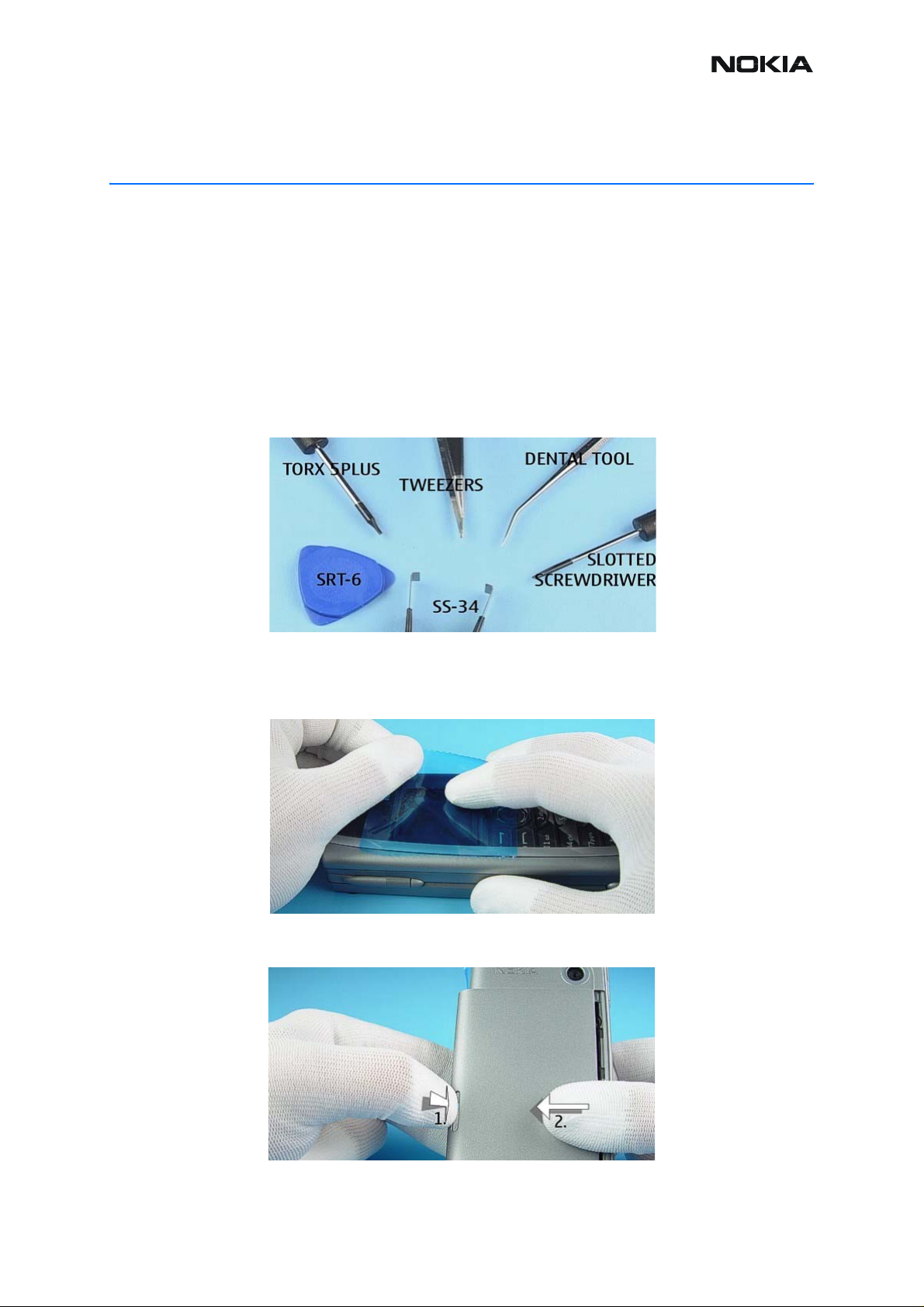
■ Required tools for disassembly
■ Disassembling lower block
1. Protect the window with a plastic foil to avoid dust and scratches.
2. Push down the BATTERY COVER LATCH before opening the BATTERY
COVER.
Issue 1 09/04 COMPANY CONFIDENTIAL 5
Copyright © 2004 Nokia. All Rights Reserved.
Page 6
RA-2/3
Nokia Customer Care 5 - Disassembly & Assembly Instructions
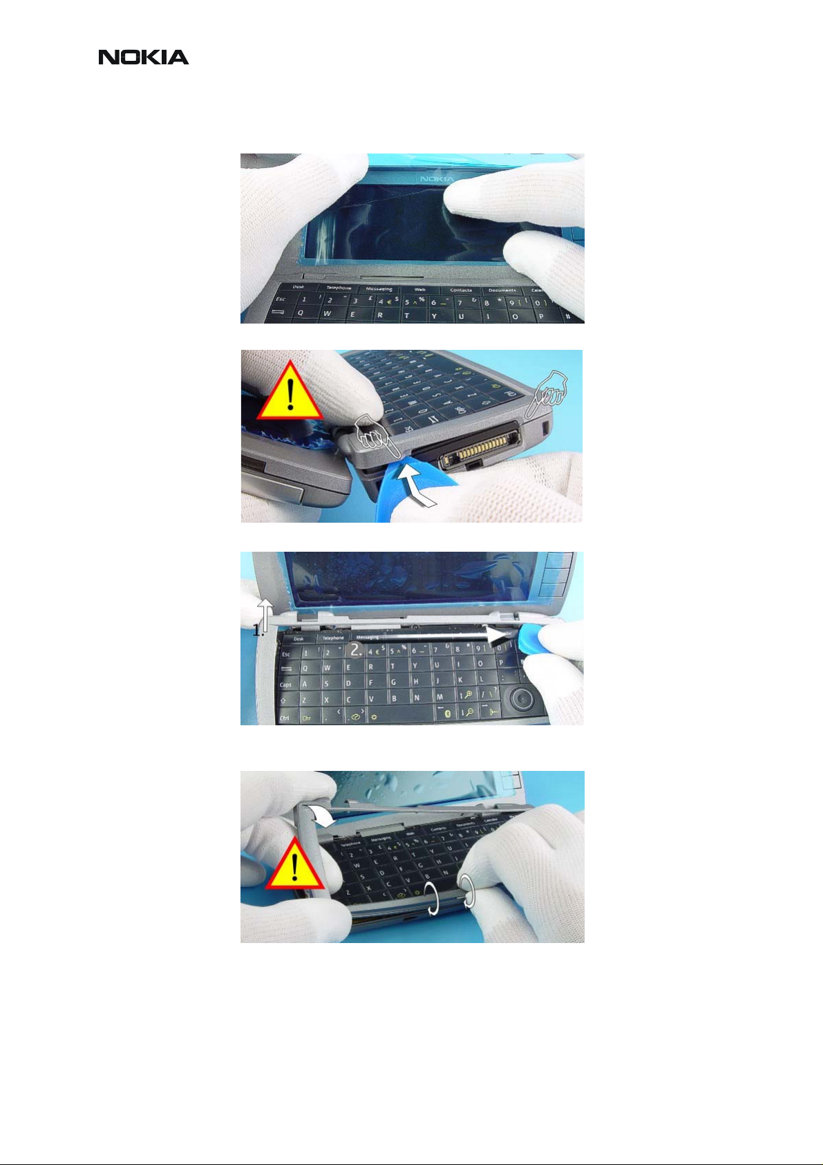
3. Fit a protective foil onto the PDA LCD MODULE.
4. Use SRT-6 to carefully open the snaps.
5. Unlock the hooks along the edge of the KEYPAD FRAME as shown.
6. Bend the left side of the KEYPAD FRAME carefully and unlock the snaps as
shown.
6 COMPANY CONFIDENTIAL Issue 1 09/04
Copyright © 2004 Nokia. All Rights Reserved.
Page 7

RA-2/3
5 - Disassebmly & Assembly Instructions Nokia Customer Care
7. Place SRT-6 between the KEYPAD FRAME and the B-COVER and open the
first snap carefully.
8. Repeat the same procedure when opening the next snap.
9. Remove the KEYPAD FRAME. Do NOT re-use the KEYPAD FRAME!
10. Remove the PDA KEYMAT.
Issue 1 09/04 COMPANY CONFIDENTIAL 7
Copyright © 2004 Nokia. All Rights Reserved.
Page 8

RA-2/3
Nokia Customer Care 5 - Disassembly & Assembly Instructions
11.Unscrew the nine, Torx Plus® size 5 screws in the order shown.
NOTE! For reassembly, reverse the order and use a Torx Plus® size 5 driver with
a torque setting of 18Ncm.
12. Remove the QWERTY ASSY.
13. Use SRT-6 to open the connector. Note! Be careful when opening the con-
nector.
14.Lift out the UPPER BLOCK.
8 COMPANY CONFIDENTIAL Issue 1 09/04
Copyright © 2004 Nokia. All Rights Reserved.
Page 9

RA-2/3
5 - Disassebmly & Assembly Instructions Nokia Customer Care
15. Use the FLEX OPENING TOOL to open the camera connector.
16.Lift the ENGINE MODULE a bit and remove it from the B-COVER.
17.Use SRT-6 to push out the CAMERA MODULE from its holder
18. Lift out the CAMERA MODULE.
Issue 1 09/04 COMPANY CONFIDENTIAL 9
Copyright © 2004 Nokia. All Rights Reserved.
Page 10

RA-2/3
Nokia Customer Care 5 - Disassembly & Assembly Instructions
19.Remove the ANTENNA with tweezers.
Note! Protect the surface of the ANTENNA. Reassemble the ANTENNA ASSY
with your fingers only.
20. Use the DC-PLUG to remove the DC-JACK.
21.Remove the MICROPHONE with tweezers.
22.The BATTERY DECK ASSY is attached to the B-COVER with six snaps. Use
SRT-6 to push out the BATTERY DECK ASSY.
10 COMPANY CONFIDENTIAL Issue 1 09/04
Copyright © 2004 Nokia. All Rights Reserved.
Page 11

RA-2/3
5 - Disassebmly & Assembly Instructions Nokia Customer Care
■ Disassembling upper block
1. Sway the FRICTION HINGE (not available as spare part) upward. Please note
that the axis is fixed to the C-COVER!
2. Use SRT-6 to push in the A-COVER LOCKING and unlock the A-COVER.
3. Remove the A-COVER ASSY. Fit a protective foil inside the A-COVER window.
4. Remove the CMT KEYMAT. Note the guide pins when reassembling.
Issue 1 09/04 COMPANY CONFIDENTIAL 11
Copyright © 2004 Nokia. All Rights Reserved.
Page 12

RA-2/3
Nokia Customer Care 5 - Disassembly & Assembly Instructions
5. Use the dental tool to open the flaps of the SHIELD.
Note! To prevent injuring yourself, always place the device on the table when ope ning the flaps. Always use a new SHIELD when reassembling.
6. Remove the SHIELD.
7. Take care of the EARPIECE. Protect the CMT LCD MODULE with a foil.
12 COMPANY CONFIDENTIAL Issue 1 09/04
Copyright © 2004 Nokia. All Rights Reserved.
Page 13

RA-2/3
5 - Disassebmly & Assembly Instructions Nokia Customer Care
8. Use tweezers to remove the EARPIECE.
9. Use SS-34 to open the LCD connector.
10.Lift out the LCD MODULE.
11.Use SRT-6 as a lever to open the A-COVER LOCKING.
Issue 1 09/04 COMPANY CONFIDENTIAL 13
Copyright © 2004 Nokia. All Rights Reserved.
Page 14

RA-2/3
Nokia Customer Care 5 - Disassembly & Assembly Instructions
12.Lift out the A-COVER LOCKING.
13.Use SRT-6 to open the connector.
14.Use a slotted screwdriver as a lever to open the clip.
15. Repeat the same procedure on the right side.
14 COMPANY CONFIDENTIAL Issue 1 09/04
Copyright © 2004 Nokia. All Rights Reserved.
Page 15

RA-2/3
5 - Disassebmly & Assembly Instructions Nokia Customer Care
16. Lift out the UI CHASSIS as shown.
17.The PDA LCD MODULE is attached with an adhesive tape to the C-COVER.
Push the LCD MODULE with two fingers slowly and the adhesive peels away.
Issue 1 09/04 COMPANY CONFIDENTIAL 15
Copyright © 2004 Nokia. All Rights Reserved.
Page 16

RA-2/3
Nokia Customer Care 5 - Disassembly & Assembly Instructions
■ Changing flex cover
1. Remove the FLEX COVER.
2. Use SRT-6 to remove the remaining adhesive tape.
3. Use tweezers to take a new FLEX COVER.
4. Place the new FLEX COVER on the UI FLEXFOIL.
16 COMPANY CONFIDENTIAL Issue 1 09/04
Copyright © 2004 Nokia. All Rights Reserved.
Page 17

RA-2/3
5 - Disassebmly & Assembly Instructions Nokia Customer Care
5. Carefully press the FLEX COVER onto the UI FLEXFOIL.
Issue 1 09/04 COMPANY CONFIDENTIAL 17
Copyright © 2004 Nokia. All Rights Reserved.
Page 18

RA-2/3
Nokia Customer Care 5 - Disassembly & Assembly Instructions
■ Reassembling keypad frame
Always use a new keypad when reassembling.
1. Place the PDA KEYMAT onto the QWERTY ASSY. Note the guide pins.
2. Always start from the left side of the QWERTY FRAME when assembling the
unit.
3. Carefully press the upper side of the QUERTY FRAME onto its place.
4. Ensure that both snaps on the front side are properly locked.
18 COMPANY CONFIDENTIAL Issue 1 09/04
Copyright © 2004 Nokia. All Rights Reserved.
Page 19

RA-2/3
5 - Disassebmly & Assembly Instructions Nokia Customer Care
5. Press both COVERS together.
Issue 1 09/04 COMPANY CONFIDENTIAL 19
Copyright © 2004 Nokia. All Rights Reserved.
Page 20

RA-2/3
Nokia Customer Care 5 - Disassembly & Assembly Instructions
[This page intentionally blank]
20 COMPANY CONFIDENTIAL Issue 1 09/04
Copyright © 2004 Nokia. All Rights Reserved.
 Loading...