Nokia 830 Service manual

4.5 (2)

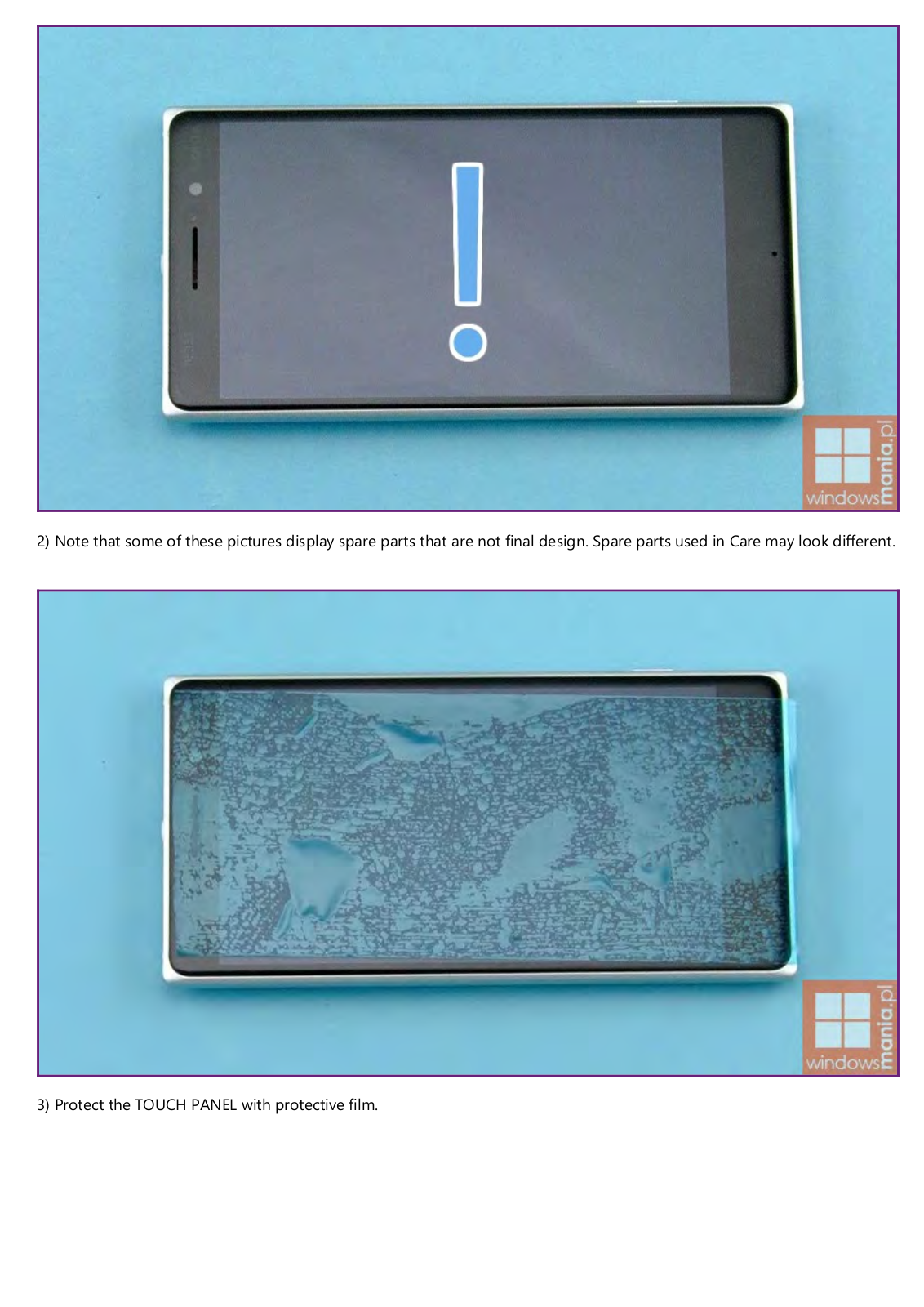
2) Note that some of these pictures display spare parts that are not final design. Spare parts used in Care may look different.

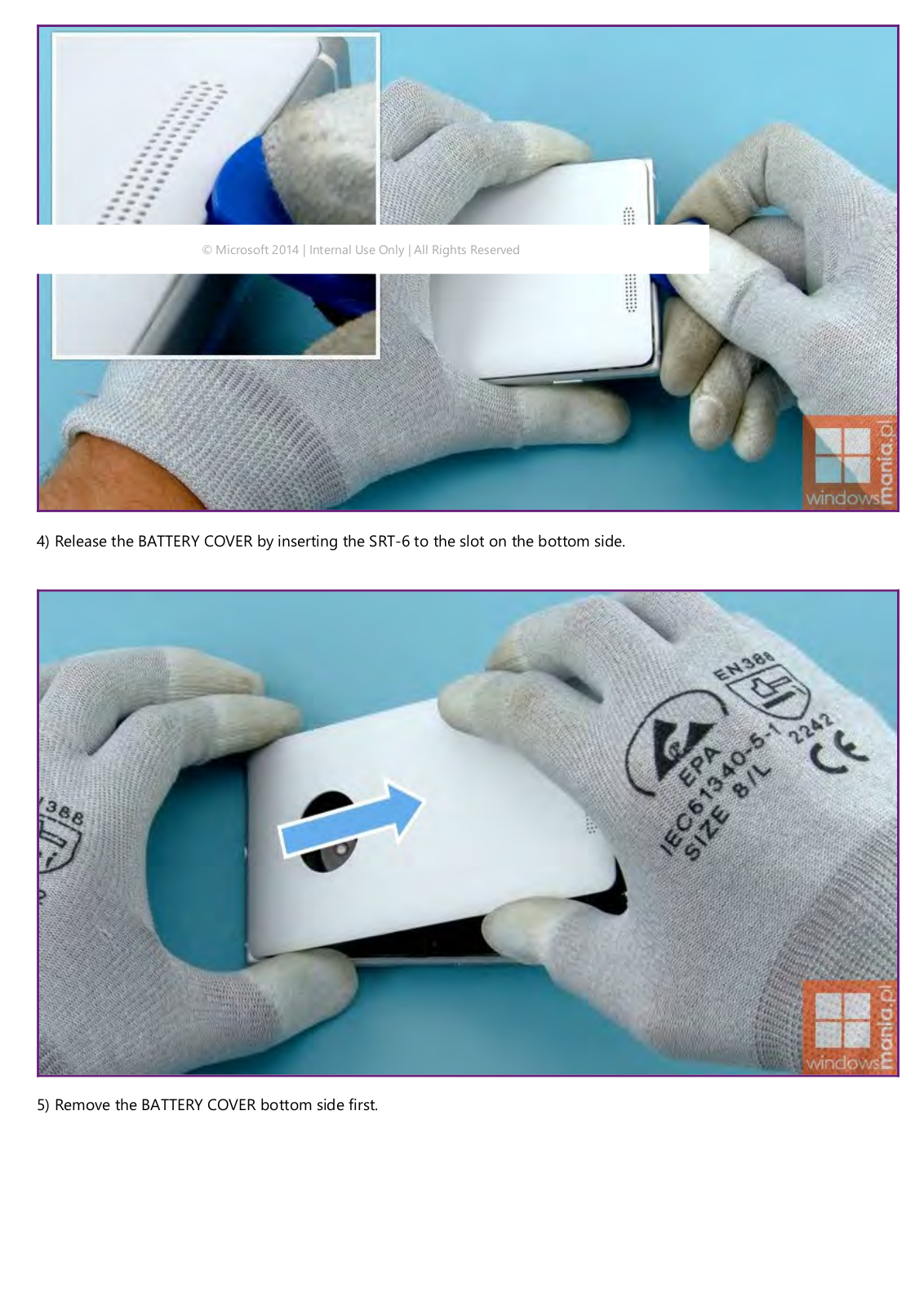
3) Protect the TOUCH PANEL with protective film.

Nokia 830 Service manual

© Microsoft 2014 | Internal Use Only | All Rights Reserved

4) Release the BATTERY COVER by inserting the SRT-6 to the slot on the bottom side.

5) Remove the BATTERY COVER bottom side first.

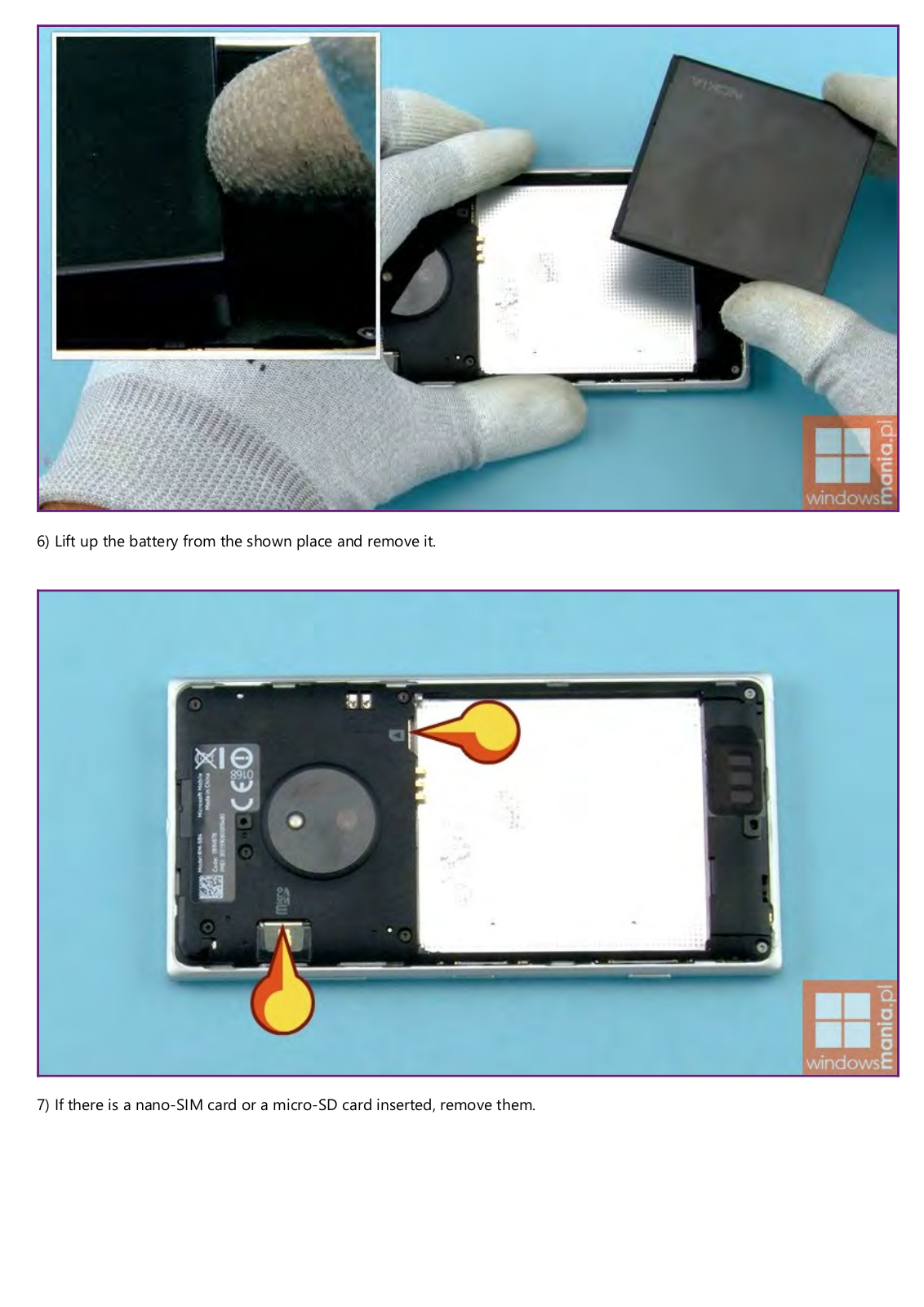
6) Lift up the battery from the shown place and remove it.

7) If there is a nano-SIM card or a micro-SD card inserted, remove them.

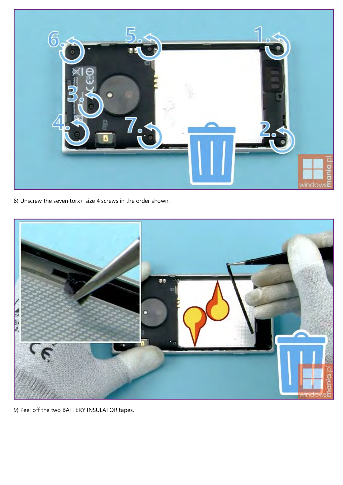
8) Unscrew the seven torx+ size 4 screws in the order shown.

9) Peel off the two BATTERY INSULATOR tapes.

10) Release the leg of the ENGINE COVER from the CHASSIS by pushing from the two shown places with the SS-93. The legs of the ENGINE COVER are very weak so be careful not to bend them.

11) Release the other leg of the ENGINE COVER from the CHASSIS.

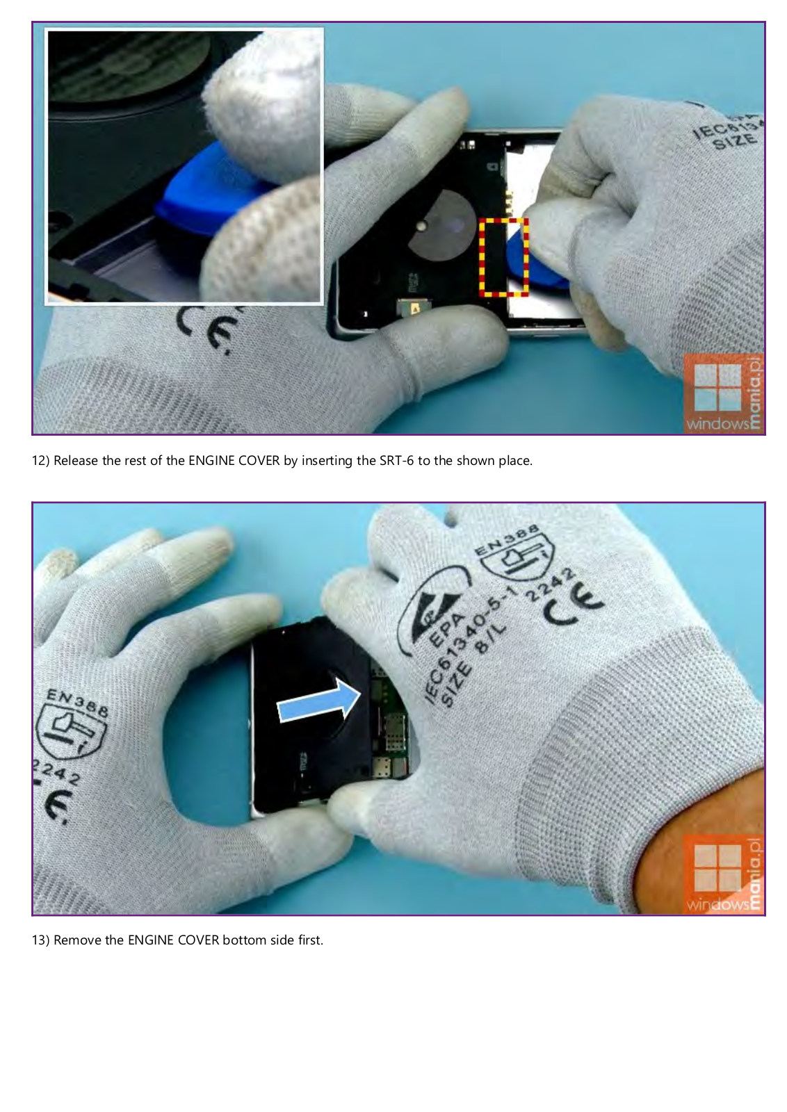
12) Release the rest of the ENGINE COVER by inserting the SRT-6 to the shown place.

13) Remove the ENGINE COVER bottom side first.

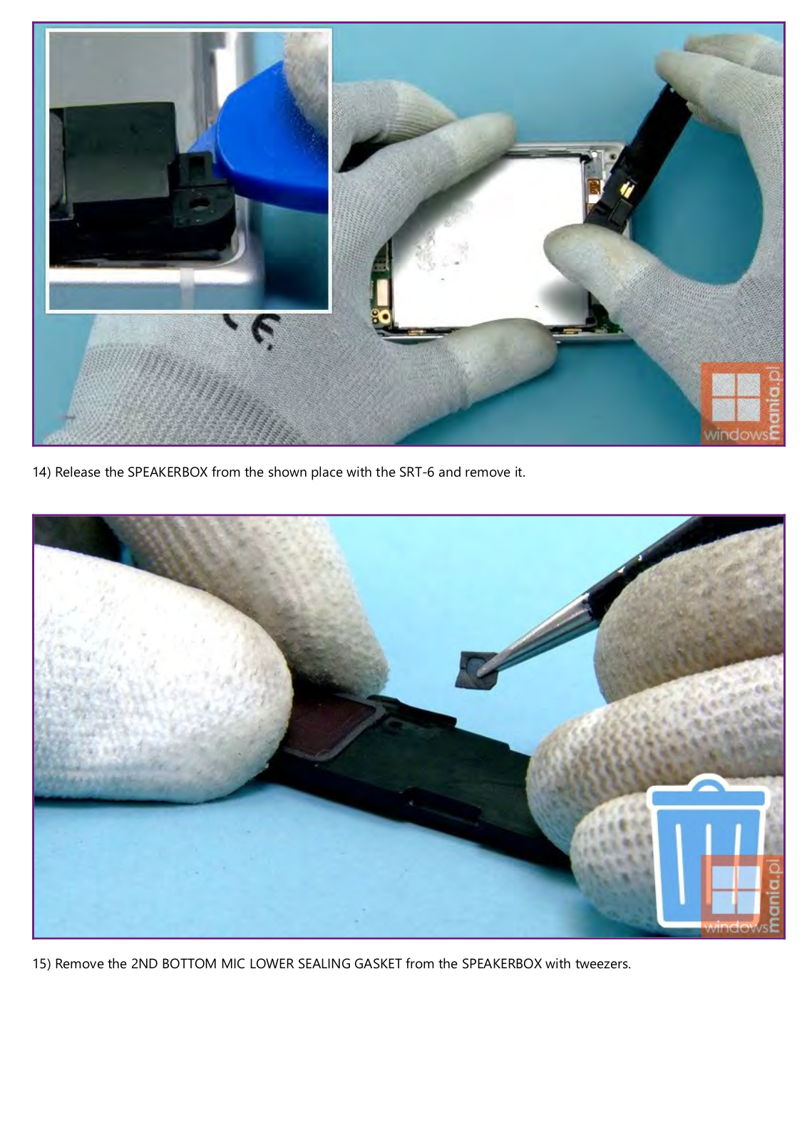
14) Release the SPEAKERBOX from the shown place with the SRT-6 and remove it.

15) Remove the 2ND BOTTOM MIC LOWER SEALING GASKET from the SPEAKERBOX with tweezers.

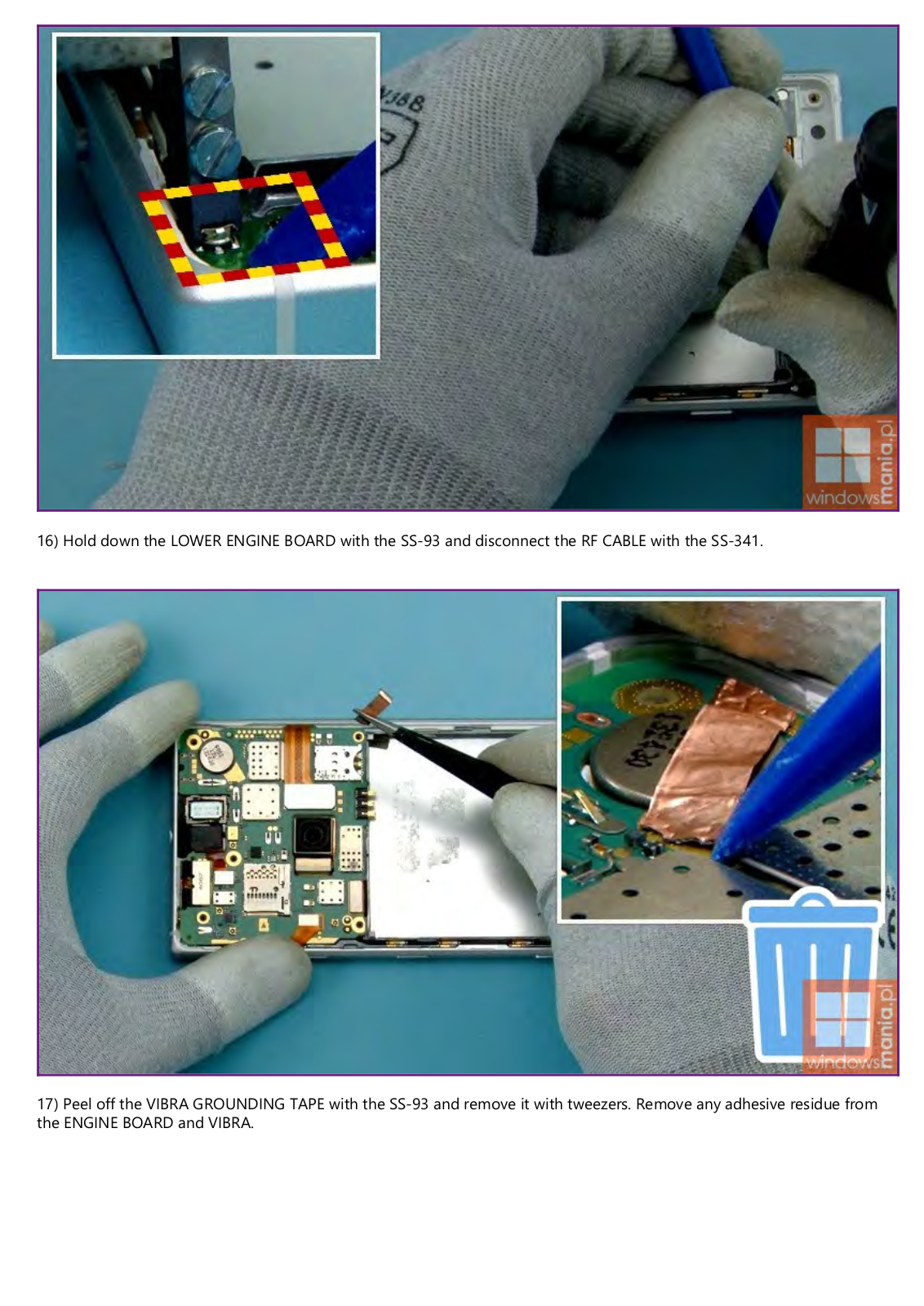
16) Hold down the LOWER ENGINE BOARD with the SS-93 and disconnect the RF CABLE with the SS-341.

17) Peel off the VIBRA GROUNDING TAPE with the SS-93 and remove it with tweezers. Remove any adhesive residue from the ENGINE BOARD and VIBRA.

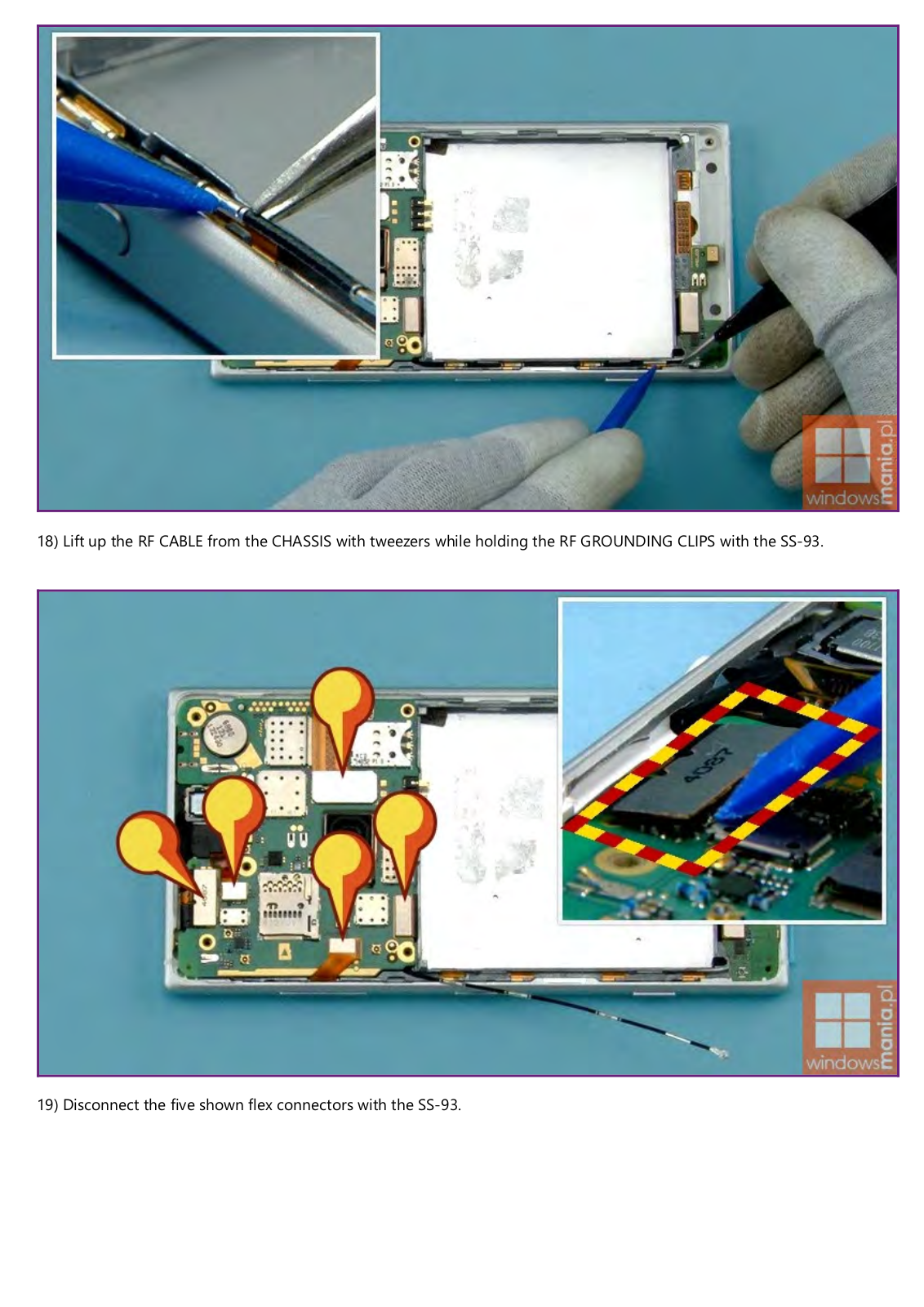
18) Lift up the RF CABLE from the CHASSIS with tweezers while holding the RF GROUNDING CLIPS with the SS-93.

19) Disconnect the five shown flex connectors with the SS-93.

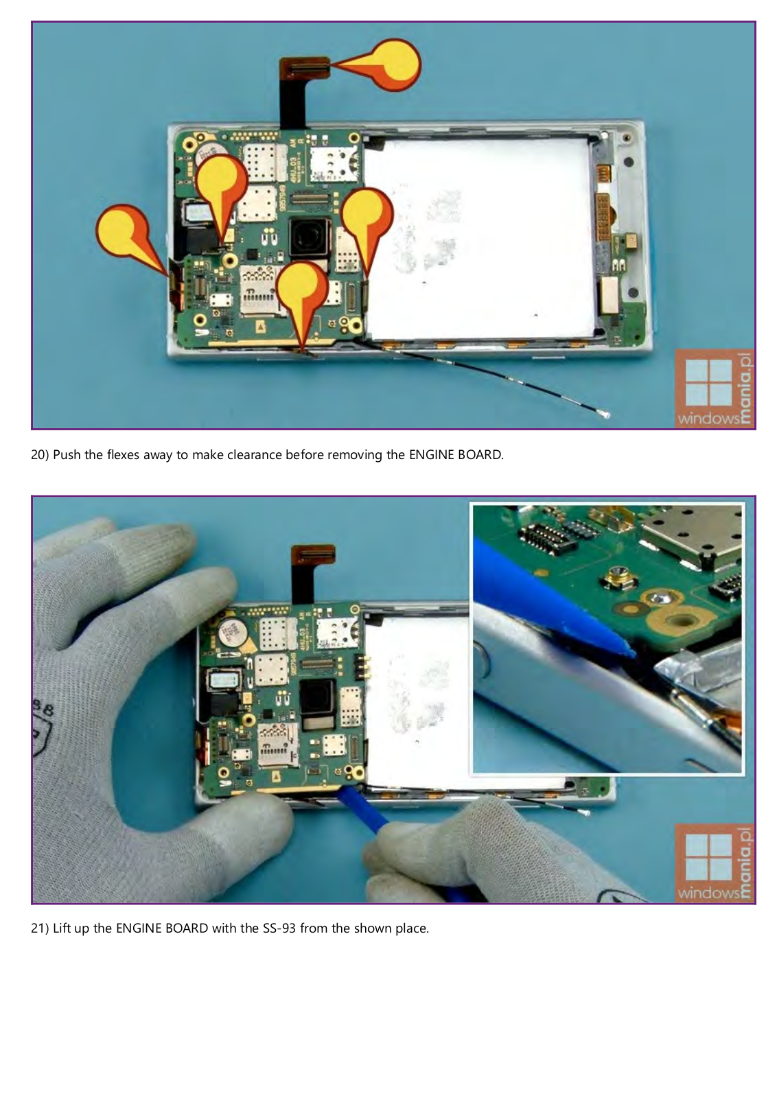
20) Push the flexes away to make clearance before removing the ENGINE BOARD.

21) Lift up the ENGINE BOARD with the SS-93 from the shown place.

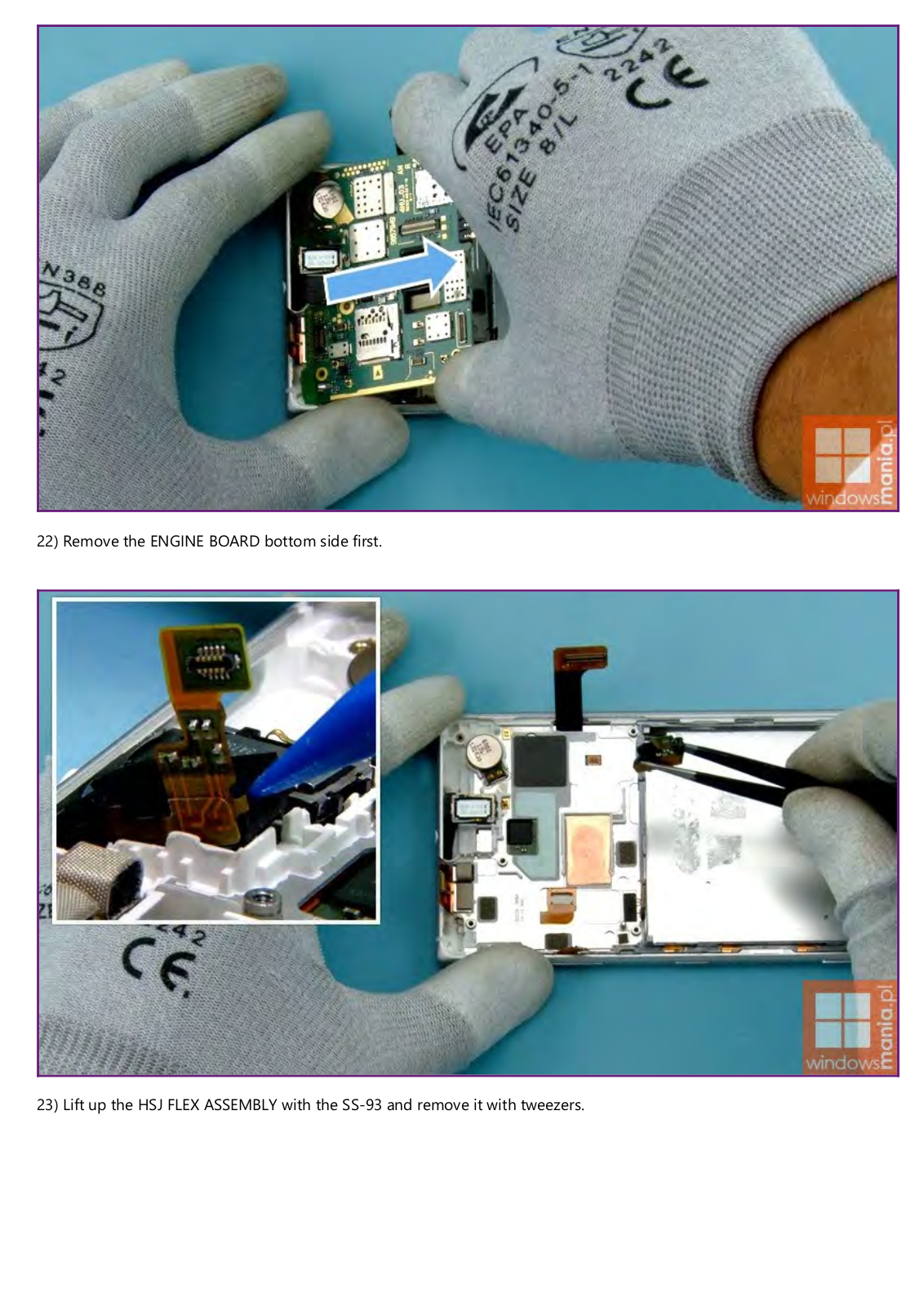
22) Remove the ENGINE BOARD bottom side first.

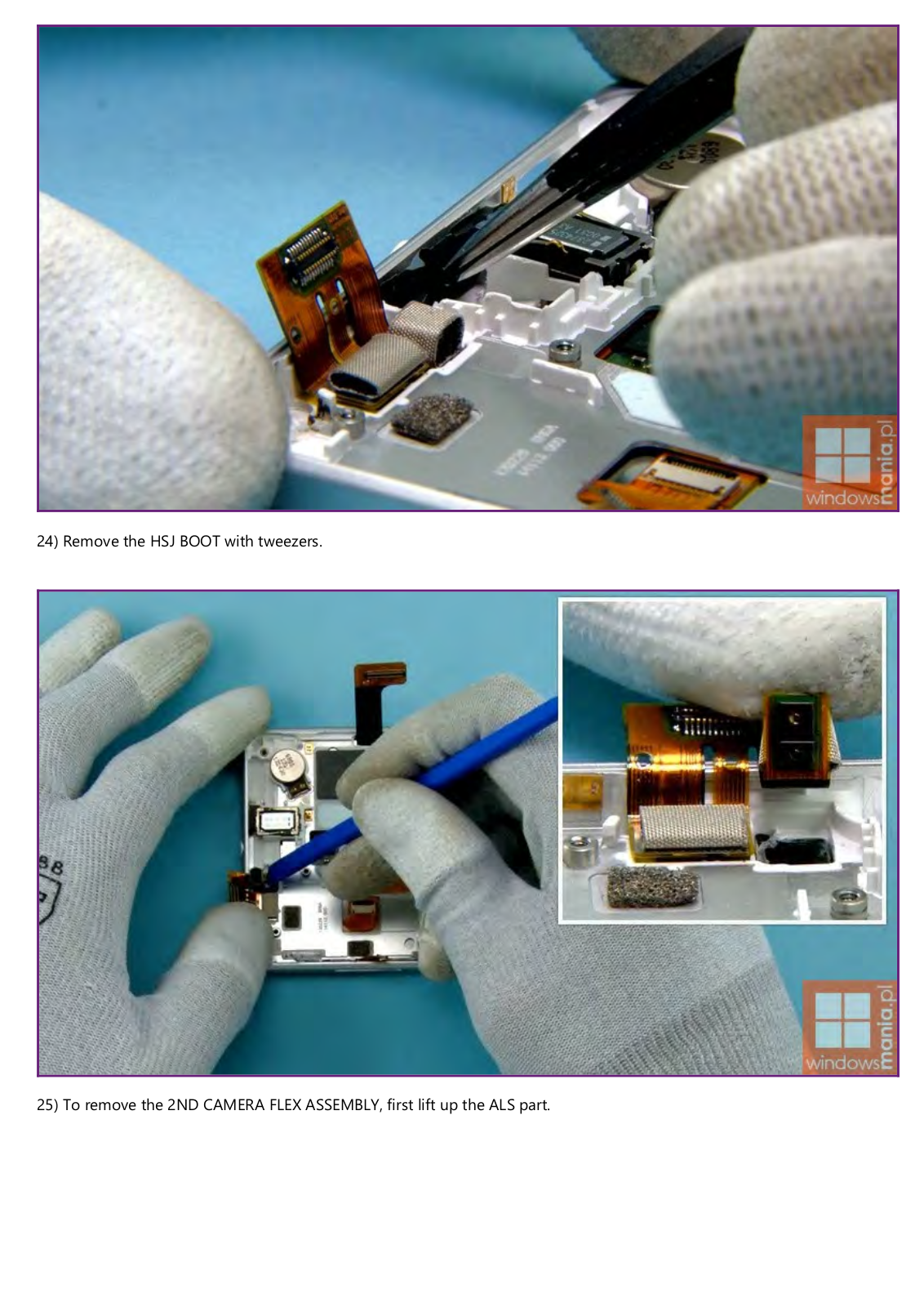
23) Lift up the HSJ FLEX ASSEMBLY with the SS-93 and remove it with tweezers.

24) Remove the HSJ BOOT with tweezers.

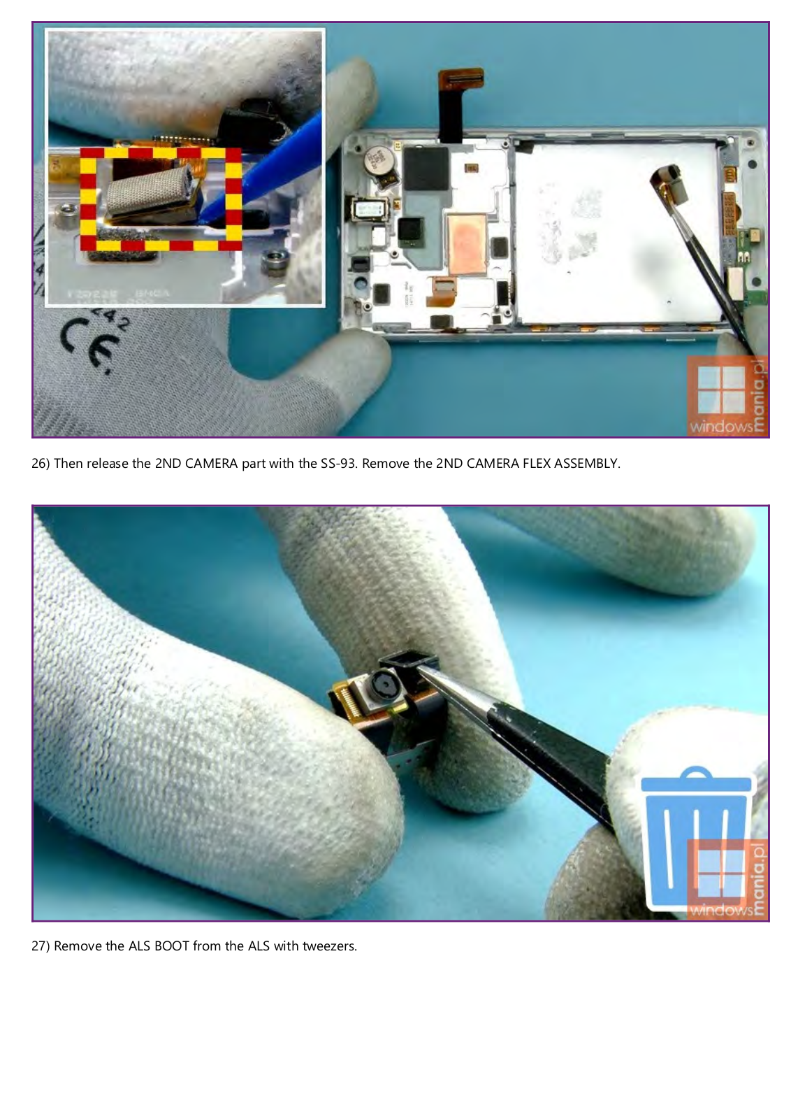
25) To remove the 2ND CAMERA FLEX ASSEMBLY, first lift up the ALS part.

26) Then release the 2ND CAMERA part with the SS-93. Remove the 2ND CAMERA FLEX ASSEMBLY.

27) Remove the ALS BOOT from the ALS with tweezers.

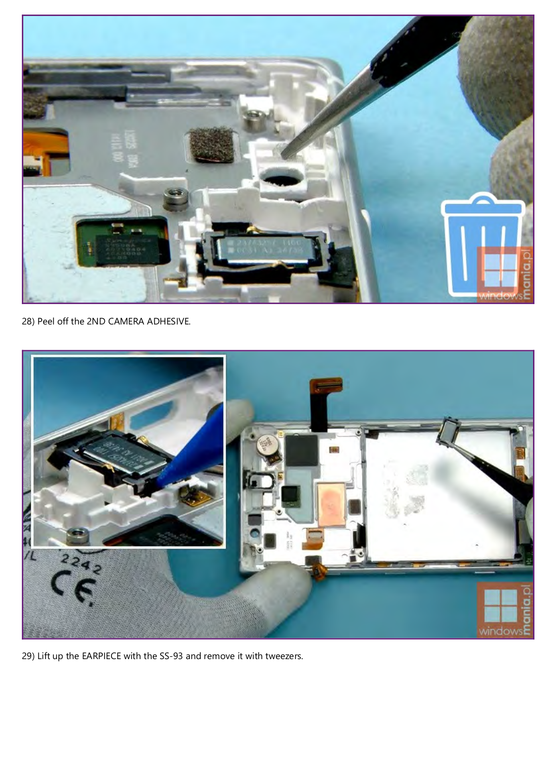
28) Peel off the 2ND CAMERA ADHESIVE.

29) Lift up the EARPIECE with the SS-93 and remove it with tweezers.

30) Remove the EARPIECE GASKET with tweezers.

31) Remove the EARPIECE SEALING GASKET with tweezers.

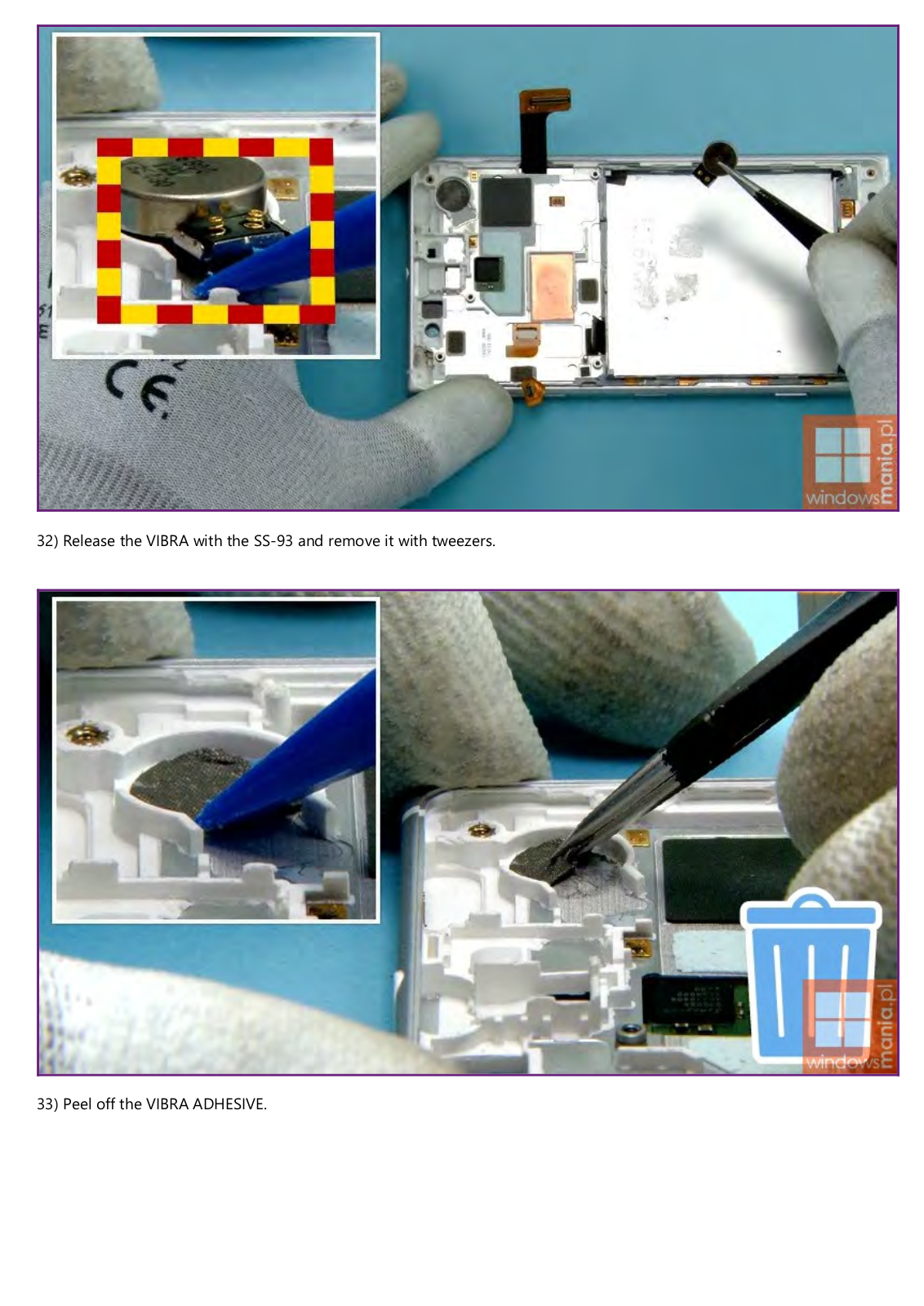
32) Release the VIBRA with the SS-93 and remove it with tweezers.

33) Peel off the VIBRA ADHESIVE.

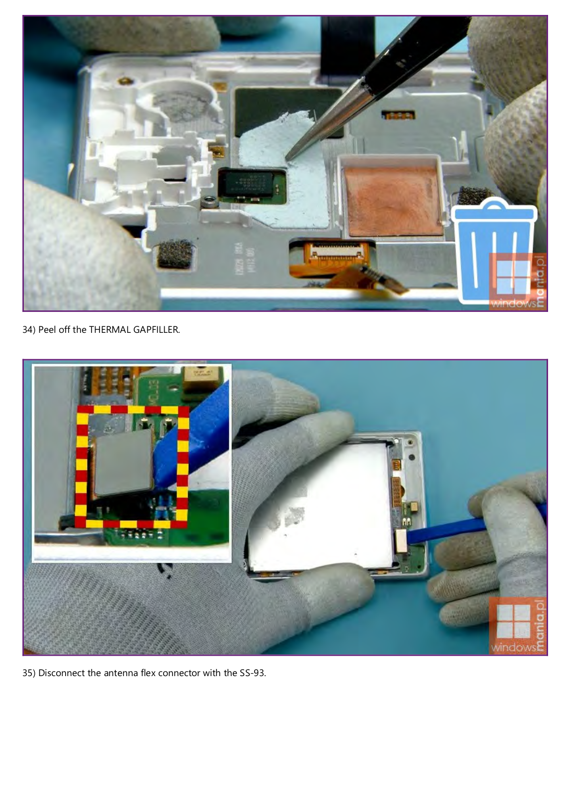
34) Peel off the THERMAL GAPFILLER.

35) Disconnect the antenna flex connector with the SS-93.

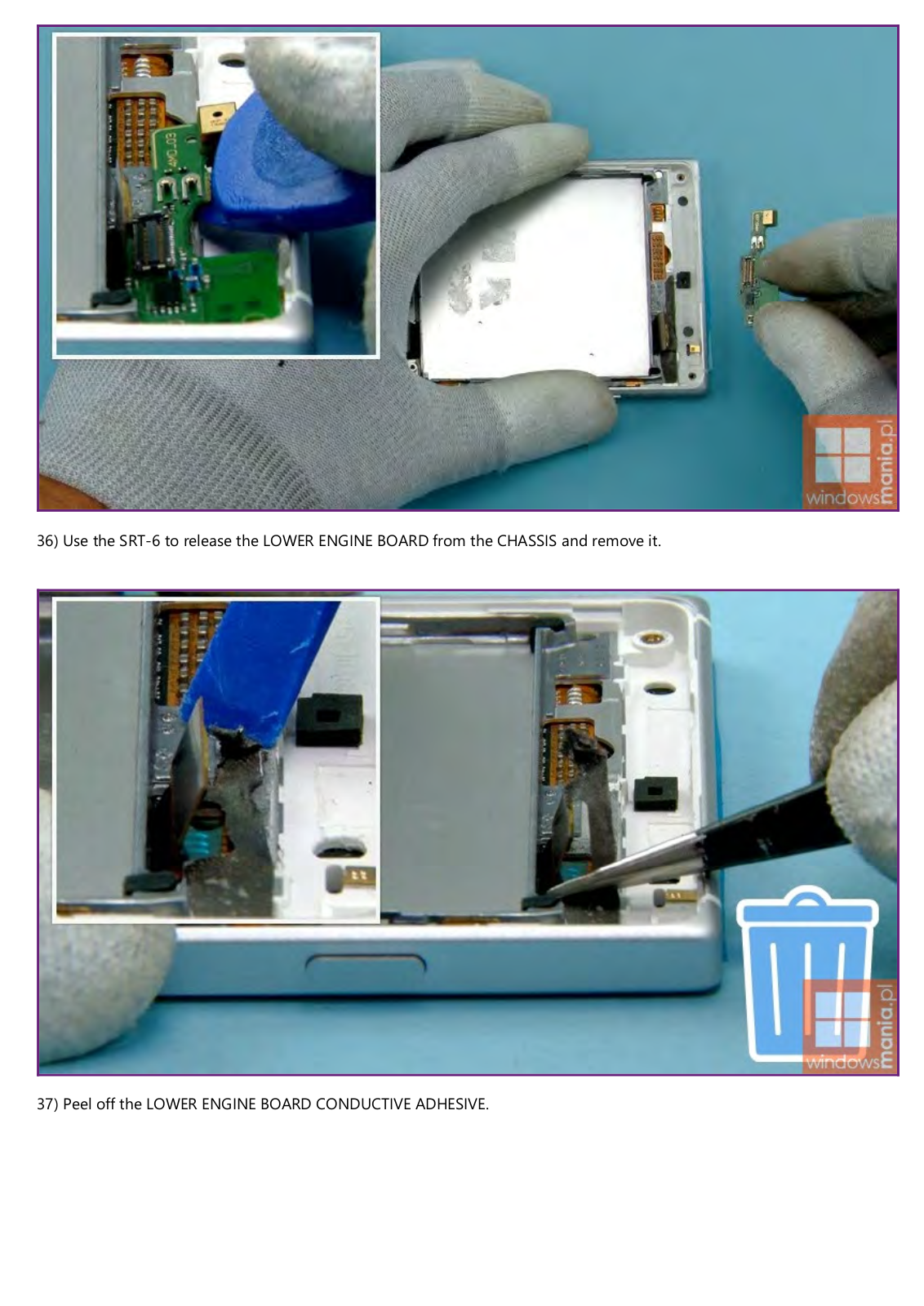
36) Use the SRT-6 to release the LOWER ENGINE BOARD from the CHASSIS and remove it.

37) Peel off the LOWER ENGINE BOARD CONDUCTIVE ADHESIVE.

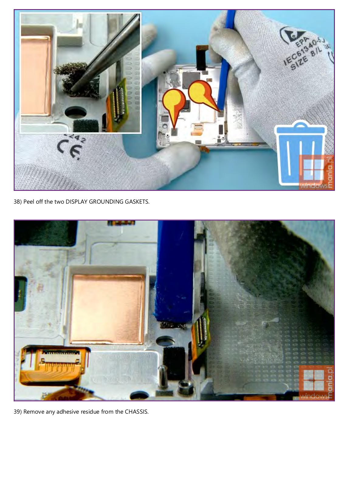
38) Peel off the two DISPLAY GROUNDING GASKETS.

39) Remove any adhesive residue from the CHASSIS.

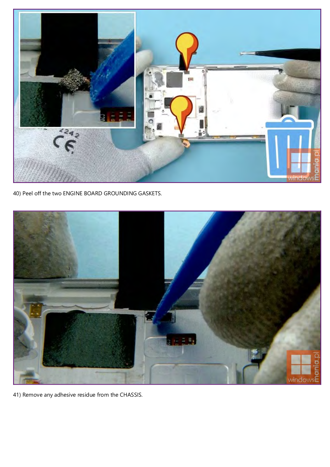
40) Peel off the two ENGINE BOARD GROUNDING GASKETS.

41) Remove any adhesive residue from the CHASSIS.

Loading...
+ 45 hidden pages