

Page 1

Programmes After Market Services
NSD-5 Series Transceivers
7. Service Software Instructions
Issue 1 05/02 Nokia Corporation
Page 2

NSD-5
7. Service Soft w are Instructions PAMS Technical Documentation
Page 2 Nokia Corporation Issue 1 05/02
Page 3

NSD-5
PAMS Technical Documentation 7. Service Software Instructions
Contents
Page No
WinTesla / Diego User’s Guides ................................................................................... 5
General .........................................................................................................................5
Service Software ..........................................................................................................5
Equipment Requirements .............................................................................................5
Mechanical Connections ..............................................................................................5
WinTesla Software Installation ...................................................................................6
Parts Required........................................................................................................... 6
Procedure................................................................................................................... 6
Diego Software Installation .........................................................................................7
System and Dongle Requirements ............................................................................ 7
Diego Program Installation ....................................................................................... 8
Software Installation ................................................................................................. 8
Using WinTesla / Diego with NSD-5FX Phones ........................................................9
Menu Bar .....................................................................................................................9
WinTesla Screen ..................................................................................................... 10
Getting Started ...........................................................................................................10
Setup for BUS type and COM port:........................................................................ 10
Product Menu .............................................................................................................11
New (Ctrl+R)........................................................................................................... 11
Open........................................................................................................................ 11
Initialize................................................................................................................... 12
Faultlog.................................................................................................................... 13
FLS-x Remote Update............................................................................................. 13
Exit (Alt+F4)........................................................................................................... 13
Configure Menu .........................................................................................................13
Options.................................................................................................................... 14
Buses ....................................................................................................................... 14
Directories............................................................................................................... 15
Faultlog.................................................................................................................... 15
Label Printing.......................................................................................................... 15
FLS-x....................................................................................................................... 15
Software Menu ...........................................................................................................16
Easy Flash ............................................................................................................... 16
Program ESN........................................................................................................... 16
MIN Lock................................................................................................................ 16
Flash File Programming.......................................................................................... 16
Flash File Programming.......................................................................................... 16
Procedure to Flash a Phone..................................................................................... 17
FAQs:...................................................................................................................... 18
Advanced Options................................................................................................... 19
Dealer Menu ..............................................................................................................20
PRL.......................................................................................................................... 20
Subscribe(NAM)..................................................................................................... 20
Phone Book............................................................................................................. 22
A-Key Programming............................................................................................... 22
Calling Card ............................................................................................................ 22
Warranty Information.............................................................................................. 23
Issue 1 05/02 Nokia Corporation Page 3
Page 4

NSD-5
7. Service Soft w are Instructions PAMS Technic al Documentation
Download Bitmap ................................................................................................... 23
User Data Transfer .................................................................................................. 23
View Menu ................................................................................................................23
RF Parameters ......................................................................................................... 23
Phone Identity ......................................................................................................... 24
eeprom Read............................................................................................................ 24
PPC Counters .......................................................................................................... 24
Help Menu .................................................................................................................24
Mouse Cursors......................................................................................................... 24
Reserved Keys ...........................................................................................................25
Short Cut Function Keys ...........................................................................................26
Alt Hot Keys............................................................................................................ 26
Ctrl Hot Keys .......................................................................................................... 26
Shift Hot Keys......................................................................................................... 26
Key Strokes............................................................................................................. 26
Dialog Boxes .............................................................................................................28
Common Dialog Boxes........................................................................................... 29
Custom Dialog boxes.............................................................................................. 30
Service Setups.............................................................................................................. 32
Equipment Setup for POS (Point of Sale) Flashing ...................................................32
Flash Concept for (for Central Service use only) ......................................................33
Tuning With Covers Off - Using Module Fixture MJS-24 .......................................34
Appendix 1, Vocabulary .............................................................................................. 35
Page 4 Nokia Corporation Issue 1 05/02
Page 5

NSD-5
PAMS Technical Documentation 7. Service Software Instructions
WinTesla / Diego User’s Guides
General
The name TESLA, when used by Nokia, is an acronym for TEst and Service Locals Application. Tesla for Windows (i.e. WinTesla) is a software package designed to operate in the
Microsoft Windows environment. The software package is made of two modules, the
WinTesla core module, with drivers and a service software module DLL, and a service
software module. The WinTesla module is similar to an operating system for various service modules. In this way many Nokia products can be serviced using one common software package.
NOTE: The WinTesla core module MUST be installed for ”any” service module to run.
Service Software
Due to the modular design of Service Software, various generations of Nokia products
can be serviced while sharing a similar user interface. The common user interface is
explained in the first part of this section, followed by specific module information.
The software can be used to control the phone by entering commands via PC/AT/NT, running Microsoft Windows 95, 98, or NT. If you are not familiar with the Windows interface, consult the Microsoft Windows User Guide for more information.
Equipment Requirements
Computer: PC Pentium, 100MHz minimum, or compatible. At least one unused serial
port, COM1 or COM2, one parallel port (LPT1), 5MB hard disk space, and 16MB RAM.
Display: Any supported by MS Windows (Windows 95, 98, or NT).
Operating System: running MS Windows 95, 98, or NT.
WinTesla Application Software (Product Code 8405043).
Diego Application Software (Product Code 8405139).
Software Protection Key (PKD-1) (Product Code 0750018) or FLS-2D (Product Code
0081310).
Phone-specific Service Software Module (Product Code - see phone-specific information).
Mechanical Connections
Caution: Make sure that you have switched off the PC and the printer before making
connections.
Caution: Do not connect the PKD-1 key to the serial port. You may damage your PKD-1
key.
Issue 1 05/02 Nokia Corporation Page 5
Page 6

NSD-5
7. Service Soft w are Instructions PAMS Technic al Documentation
The software controls the phone via Flash Loading Adapter (FLA-38) and RS-232/MBUS
Interface (DAU-2T) with a D25-D9 connector connected to the serial port of the PC.
Attach the protection key PKD-1 to the parallel port 1 (25-pin female D-connector) of
the PC. When connecting the PKD-1 to the parallel port, be sure that you insert the computer side of the PKD-1 to the PC (male side). If you use a printer on parallel port 1,
install the PKD-1 between the PC and your printer cable.
WinTesla Software Installation
Parts Required
From the PAMS web site, enter the following selections, starting from the home page:
Software>Product Specific Service Software>CDMA>Wintesla DCT3 CDMA Service
Software (NSD-5)
Note: A floppy disk version also is available from the PAMS web site: WT264.diskettes.zip (complete
CDMA Wintesla version) and NSD_W264.diskettes.zip (CDMA dll version). These versions, when
unzipped, will create files sized to be placed on multiple floppy disks.
Procedure
Installation steps for new WinTesla DLL
Note: Previous WinTesla installation required.
1 Check the WinTesla Core SW version on the Help menu. Select About from the
drop-down menu.
2 Make sure that you have one of the following WinTesla core SW versions 6.43. If
you don’t have it installed, read Note 1 which follows below.
3 Download the self-extracting file NSD_W264.EXE to your own workstation. Dou-
ble-click on the file to extract the actual files and to auto-load the program.
4 Note that it is not necessary to restart your computer.
5 Customer-specific software files are not included with the WinTesla software
packages. To get the necessary customer-specific files, download one or more of
the flash software packages. For specific instructions, refer to the specific Technical Bulletin releasing flash software for a particular customer / product to be
supported. Double-clicking on these packages will self-install the Config file,
flash file, PRLs, and PRIs into the appropriate locations.
Note 1: If you are installing WinTesla for the first time in your PC, the complete WinTesla Installation
Pack SW for CDMA phones is required. The complete pack includes all other drivers and core modules that are needed to run WinTesla with NSD-5 phones. This software is available from the PAMS
web page or may be ordered (Product Code 0081309). For more detailed instructions, refer to the WinTesla User Guide for CDMA using FLS-2D Dongle, document number SGY00139-EN.
Page 6 Nokia Corporation Issue 1 05/02
Page 7

NSD-5
PAMS Technical Documentation 7. Service Software Instructions
Using Zip Packages for Floppy Disks
1 Download the file (only available from the PAMS web site).
2 Double-click on the file and select Extract files.
3 Identify a location for the files to be placed.
4 Several folders are created.
5 Copy the contents of the folders to floppy disks (be sure to label the disks as
Disk 1, Disk 2, and so on).
6 Insert Disk 1 and double-click on Setup; follow the prompts to complete installa-
tion.
Diego Software Installation
System and Dongle Requirements
System Hardware
• IBM-compatible PC with Pentium processor
• At least 8 MB RAM and 8 MB of hard disk space
• One standard COM port (COM1) and one standard parallel port (LPT1)
or only the COM port if using FLC-10.
• If you are running Windows 95, make sure that the LPT1 is configured
to address 0x0378.
Dongle Type
•FLS-2D
Operating System
• Windows 95 versions: Standard A and B
• Windows 98
• Windows NT
• Windows 2000 Professional Series
Issue 1 05/02 Nokia Corporation Page 7
Page 8

NSD-5
7. Service Soft w are Instructions PAMS Technic al Documentation
Hardware Part Numbers
Item Service accessory Product Code
1 Dongle FLS-2D (dealer functions) 0750130
2 Cable AXS-4 0730090
3 Diego SW package 0774247
4 Flash Loading Adapter FLA-38 0770420
5 Mbus/Fbus Cable XCS-4 0730178
Diego Program Installation
The InstallShield Wizard install program makes installation of the software simple. All
the necessary files are bundled into one executable installation package, ensure proper
installation.
Software Installation
Step 1:
Step 2:
Step 3:
Step 4:
Step 5:
The installation file will be identified as Diego_130.exe. Double-click on this file.
Note: The installation package requires that the system C:\ drive have a minimum of 8 MB available
disk space; otherwise, an error dialog box may appear.
(If you already have a version of Nokia Diego installed on your computer and are either
updating the version or wish to remove it.) Select the action you wish to perform.
You can either accept the default location for Nokia Diego software (preferred) or specify
your own location. Use the Browse... button to locate and select the desired destination
folder and select your choice. Select the Next > button to continue, the < Back button
to return to the previous dialog, or the Cancel button to exit.
Setup status is provided, describing the actions being performed. As the program installation progresses, the status bar updates with percent complete information.
When installation is complete, you may either reboot your computer now or later. Please
note that the Nokia Diego software tool will not operate until your computer has been
rebooted.
For more detailed installation instructions, refer to the Nokia DIEGO User Guide, document number SGY00140-EN. The document is located in the Nokia DIEGO folder created
during installation (path = C\Program Files\Nokia Mobile Phones\Nokia Diego for default
installation). The document also may be accessed by selecting Help from the toolbar
Page 8 Nokia Corporation Issue 1 05/02
Page 9

NSD-5
PAMS Technical Documentation 7. Service Software Instructions
while the Diego software is running.
Using WinTesla / Diego with NSD-5FX Phones
The WinTesla application “WinTesla.exe” is phone independent. It relies on separate,
phone-specific modules to provide communication, menus, and test algorithms.
For each phone type (family), a phone interface module and menu module are required.
The modularity of WinTesla allows support for other languages. As a result, one phone
type may have one phone interface module and several menu modules, all in different
languages.
WinTesla allows the user to select the desired language (if available), and automatically
loads the correct phone interface module for the connected phone. When a different
phone type is connected, WinTesla loads that phone’s interface and associated menus.
Menu Bar
The Service Software package has two menu bar configurations. The first is an abbreviated version that contains the minimum number of menus that allows package configurations when a phone is NOT connected. The second configuration is described here:
The menu bar MUST only contain the following menus for the Service Software package
when a phone is connected:
• Product*
• Configure*
• Tuning (not available with FLS-2D)
• Testing (not available with FLS-2D)
• Software (not available with FLS-2D)
• Dealer
• View
• Help*
(* - Always displayed, even if a phone is not connected.)
The menu is divided into sections that are indicated with menu separators. Each section
identifies a logical difference from itself and other sections (e.g., between transmitter
and receiver). Any items that are required to be added to a menu list will be added to the
bottom of the appropriate menu selection list.
If a new item that is common to two or more phone types is to be added, that menu item
will become a common menu item.
Issue 1 05/02 Nokia Corporation Page 9
Page 10

NSD-5
7. Service Soft w are Instructions PAMS Technic al Documentation
The menu lists will use the Microsoft symbol after an item name to indicate that selecting that item will not initiate an operation immediately.
A dialog box will be displayed for the user to select options or type in data and press the
OK button before the operation is performed.
If WinTesla cannot find the file, op_id.val, which contains the Login IDs, then the OK
button will not be enabled. Press the Cancel button and only the fault logging feature of
WinTesla will be deactivated.
WinTesla Screen
The main WinTesla screen (if no phone is attached) is displayed with three menu items at
the top of the screen and a status bar at the bottom.
The information on the left of the status bar will be used to provide information when
WinTesla is performing tasks: such as reading data from the phone. The status bar also
includes the name of the current user.
Getting Started
Setup for BUS type and COM port:
When you have installed the WinTesla core software with PKD–1 drivers and the product
specific DLL software, the next step is to tell the software what kind of hardware connection you are using.
1. Select the correct COM Port. For example, COM1.
2. Select the Hardware Type. If you are using the 3-box setup, then choose Combox for
hardware type. If you are using the FLS dongle, choose Dau for MBUS.
3. Select the Media, For example, MBUS.
Page 10 Nokia Corporation Issue 1 05/02
Page 11

NSD-5
PAMS Technical Documentation 7. Service Software Instructions
4. Press Add to save configuration.
When you start using the WinTesla program with a new phone you should:
Select New, then the program starts to scan the phone that has been connected to the
PC or;
After the product-specific DLL has been selected, it will be displayed on the bottom of
the PC screen. The version and date of the product-specific DLL is also displayed.
Product Menu
New (Ctrl+R)
The ‘New’ function (which can also be activated by pressing Ctrl+R) is used to scan for a
phone when either the automatic rescan option is off or the automatic rescan timer has
not expired (see Configure>Options section for automatic rescan).
If the phone type is unrecognized or unsupported by the current WinTesla system, then a
warning message will be displayed.
If the phone is changed (with the same phone type only the serial number is changed),
the phone will be initialized into local mode. If the phone is changed to a different phone
type, the current DLLs are unloaded and new ones are loaded for that phone.
If the Quick/RF Info view is open, the window will be automatically updated.
If the Phone Information view is open, it will be automatically updated.
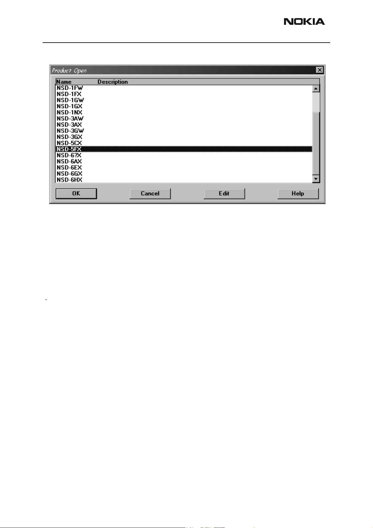
Open
The ‘Open’ function allows you to ‘force load’ a phone interface, even if there is no phone
connected to the system.
Issue 1 05/02 Nokia Corporation Page 11
Page 12
NSD-5
7. Service Soft w are Instructions PAMS Technic al Documentation
A dialog box will appear and a list of supported phone types. To select a particular phone,
highlight the phone type name and click OK.
Clicking on Cancel will stop the request and no new phone type will be loaded.
Loading a phone interface will disable the automatic rescan function (see Configure>Options section for automatic rescan).
Initialize
Activation Status Bar Text
Alt, P, I Opens a submenu for the Normal Mode and the Local Mode.
Normal Mode
Activation Status Bar Text
Alt, P, N Initializes the phone to normal (cellular) mode F5.
When the normal mode has been activated or the program has been started, self–test
results will be gathered from the MCU. If any fault was found in the tests, an error message is shown. If the normal mode has been set successfully (no self–test error has been
found), and paging listening has been started, the used AFC value is requested from MS.
Initialization routine checks the phone’s cellular type and, if it is unsupported, the phone
application unloads the DLLs.
The After Market Services SW automatically sets the MS state to normal mode when
needed.
Page 12 Nokia Corporation Issue 1 05/02
Page 13

NSD-5
PAMS Technical Documentation 7. Service Software Instructions
If the phone identification view is open, the window will be updated automatically. Also,
if the RF Information Window is open, it will be updated to quick info view.
Local Mode
Activation Status Bar Text
Alt, P, L Initializes phone to local mode
Shift + F5
Selection will change the MS state to local. When the user selects item from Testing or
Tuning menus, the After Market Services SW software will automatically change the MS
state to local.
The After Market Services SW automatically sets the MS state to normal mode when
needed.
Also, if quick info view is open, it will be updated to RF Information view.
aultlog
F
Not in use at this time.
FLS-x Remote Update
FLS-X Remote Update is used for updating the flashing licenses contained in the FLS-X
dongle.
Exit (Alt+F4)
Selecting this option will shut down the WinTesla program.
Configure Menu
The Configure menu allows you to set up such items as directory paths, user interface
language and faultlog options.
Issue 1 05/02 Nokia Corporation Page 13
Page 14

NSD-5
7. Service Soft w are Instructions PAMS Technic al Documentation
Options
Language
This option allows you to change the language used in the WinTesla application.
User ID
Allows the user ID to be entered if the user’s name is setup in the opt_id.val (validation)
file.
M2BUS COM Port
This option allows you to select which communications port the phone is to be connected. The change will take place immediately after pressing the OK button.
Buses
Setup for BUS type and COM port:
When you have installed the WinTesla core software with PKD–1 drivers and the product
specific DLL software, the next step is to tell the software what kind of hardware connection you are using.
Page 14 Nokia Corporation Issue 1 05/02
Page 15

NSD-5
PAMS Technical Documentation 7. Service Software Instructions
1. Select the correct COM Port. For example, COM1.
2. Select the Hardware Type. For FLS-2, select DAU for MBUS. In case of 3–box flash
concept, select Combox for MBUS.
3. Select the Media, For example, MBUS.
4. Press Add to save configuration.
Directories
This function allows you to organize your data into different directories.
The directories already exist when the WinTesla core software is installed. If an invalid
directory is entered, then an error message will be displayed.
The use of a backslash (‘\’) at the end of the directory name is optional. Clicking on the
OK button will save your changes.
Faultlog
Not in use at this time.
Label Printing
Only those authorized to print labels and who have a label printer and dongle will use
this option.
FLS-x
This dialog box can be used to see how many licenses are left on a FLS-2D dongle or to
uncheck the FLS check box if using the 3-box setup.
Issue 1 05/02 Nokia Corporation Page 15
Page 16

NSD-5
7. Service Soft w are Instructions PAMS Technic al Documentation
Software Menu
Easy Flash
Easy flash is used at POS, using customer-specific software bundles.
Program ESN
Program ESN is only used by authorized personnel at certain locations to program an
ESN of a phone whose part containing the ESN was replaced.
MIN Lock
MIN lock is used to read the min lock of a phone that has min lock in order to do the
repair. Used by repair centers only!
Flash File Programming
This command is used for flashing new software into the phone. While flashing the
phone, user is shown the flashing progress towards completion.
Status dialog box is shown during flashing. After the phone is flashed Authority ID is set
to the phone
Flash File Programming
The Flash Phone dialog box contains the following items:
Save User Data:
Page 16 Nokia Corporation Issue 1 05/02
Page 17

NSD-5
PAMS Technical Documentation 7. Service Software Instructions
This option decides if user data (end user settings) will be kept.
Yes The user data will be saved (recommended).
No Select if there is no need to save user data (new phone).
Advanced Options Select only in special cases.
BUTTONS:
Auto File Select
WinTesla will find a correct image for a connected phone according to its hardware ID
and product code.
Browse
Click this button to select a flash image.
Read Ver
Displays software version of the phone.
Clear/Stop
Clear the flash window. Stops saving user data during flashing.
Flash/Restore
Flashing a software into the phone or restore data to a phone.
Authority ID
Programs the Authority ID. By default, Authority ID is programmed automatically after
flashing. There is no need to do it manually.
Close button
Closes the dialog button and does not start flashing.
Procedure to Flash a Phone
1. Decide Which Options to use
There are three options: Yes, No, and Advanced Options. Yes will keep all the user data.
No will erase all user data. Advanced Options will let you decide what kind of data you
want to keep during flash.
Issue 1 05/02 Nokia Corporation Page 17
Page 18

NSD-5
7. Service Soft w are Instructions PAMS Technic al Documentation
2. Select Flash image (or let WinTesla decide for you)
You can select a flash file by clicking the Browse button. Or, you can leave the file name
field empty and let WinTesla decide which flash image to use. Please note this requires a
phone specific .cfg file be put into .../misc directory.
3. Flash
FAQs:
How to select flashing device?
Go to Configure Menu/FLS–X and check Use Fls–x for POS, otherwise uncheck it.
If the phone is totally dead, go to the Advanced Options and select Flash Dead Phone.
Then flash the phone.
What if error occurs during the user data saving?
No damage is done to your phone at this stage. So go ahead and flash it again.
What if error occurs during flashing?
If the phone is dead after dead phone flash, you must re-tune the phone.
What if error occurs after EEPROM resetting?
This means that the EEPROM data is damaged. But if you selected Yes to Save User Data,
all the user data is saved on the disk. Check your phone. If the phone is dead, select Flash
Dead Phone, then flash it to get the phone to work. Restore all the data without flash. To
do this, go to advanced options, and select Restore Data Only.
Page 18 Nokia Corporation Issue 1 05/02
Page 19

NSD-5
PAMS Technical Documentation 7. Service Software Instructions
Advanced Options
Initialize EEPROM
This option will cause phone data resetting to factory value, if no other user data is
selected to keep (e.g., Keep RF). If one of the user data options is selected to Keep..., after
flashing and resetting phone data to factory value, the data will be loaded back.
Keep RF
This option will keep the RF tuning data even if Initialize EEPROM is selected.
Keep NAM
This option will keep the NAM data even if Initialize EEPROM is selected.
Keep PRL
This option will keep the PRL even if Initialize EEPROM is selected.
Keep Phone Book
This option will keep the Phone book (SCM) even if Initialize EEPROM is selected.
Keep UI
This option will keep the UI settings even if Initialize EEPROM is selected.
Keep SMS & Call Logs
This option will keep the SMS (short messages) and Call Logs even if Initialize EEPROM is
selected.
Issue 1 05/02 Nokia Corporation Page 19
Page 20

NSD-5
7. Service Soft w are Instructions PAMS Technic al Documentation
Authority ID Programming
This option allowss the Authority ID to be programmed after flashing.
Flash Dead Phone
Select only if a totally dead phone is involved. When this option is on, all other options
except Authority ID Programming will be ignored.
Restore Data Only
If an error happens during the flashing, WinTesla will quit the flashing session. Saved
data will not be removed and can be restored by selecting this option. All other choices
need to be kept the same as that in the flash session.
Default option setting
This option is recommended. Especially when you are not familiar with all the options.
Dealer Menu
PRL
(Preferred Roaming List) Makes it possible to load a new PRL to the phone.
Subscribe(NAM)
Makes it possible to program the phone number (NAM) to the phone. It also includes
other settings such as system ID (SID) and paging channel settings.
Page 20 Nokia Corporation Issue 1 05/02
Page 21

NSD-5
PAMS Technical Documentation 7. Service Software Instructions
Buttons:
NAM Programming may be done using the phone keypad. First, enter the NAM programming mode accessible by keypad entry (*3001#12345#). The limits of the values are
mentioned in brackets.
Note: The program does not support fields that are not enabled.
NAM Selection
Selects NAM contents to be displayed.
Load File
Prompts user to select a file containing NAM information.
Save File
Allows user to save screen contents to a file.
Read File
Reads phone contents to screen.
Write Phone
Writes contents of the screen to the phone.
Set Default
Issue 1 05/02 Nokia Corporation Page 21
Page 22

NSD-5
7. Service Soft w are Instructions PAMS Technic al Documentation
Sets selection as the default.
Phone Book
This function allows the user to create, edit, or load the phone book to the phone or to
download from the phone to a personal computer.
A-Key Programming
This option allows you to program the Authentication Key (A-Key) of the phone. The
A-Key can never be read from the phone -- only programmed to the phone by overwriting the previous value.
Buttons:
To program the A-key, a valid A-Key plus a valid checksum must be entered as one complete number.
• Valid A-Key number = 6 to 20 digits (e.g., XXXXXXXXXX)
• Valid checksum = 6 digits (e.g., YYYYYY)
Example:
A-Key entry would be XXXXXXXXXXYYYYYY
Write Selected
Writes the highlighted selection to the selected NAM in the phone if the A-Key is valid.
Otherwise, an error message is displayed.
Write All
Writes both the A-Key numbers to the corresponding NAM of the phone if the A-Key is
valid. Otherwise, an error message is displayed.
Calling Card
Calling Card allows you to enter your calling card information into the phone for use
when making a calling card call.
Page 22 Nokia Corporation Issue 1 05/02
Page 23

NSD-5
PAMS Technical Documentation 7. Service Software Instructions
Warranty Information
This menu is for service purposes. It includes, for example, warranty information and
manufacturing date reading.
Download Bitmap
Allows you to download your own bitmap as long as it is the right size and pixels.
User Data Transfer
This item is used to switch user data from one phone to the next. You hook the phone up
and click on read. It reads all the data. Then, hook the new phone up and click on write —
all the data will be written to the new phone.
View Menu
RF Parameters
(used only for Special Service purposes).
Issue 1 05/02 Nokia Corporation Page 23
Page 24

NSD-5
7. Service Soft w are Instructions PAMS Technic al Documentation
Phone Identity
By using the menu, the user can read:
• Phone flash software version information
• Serial number (ESN)
• Product Code
• Hardware version
• Ordering number (if used)
eeprom Read
Eeprom Read allows you to enter an eeprom handle and read it, edit it, and write it.
PPC Counters
The PPC Counters dialog box enables you to read the counters from a phone and save
them to a file.
Help Menu
The Help User Interface is the standard Windows help tool named WinHelp. The contextsensitive help is activated with the <F1> key. Help also contains “Using Help”, which
describes how to use the Help facility. Refer to the Windows manual for detailed description of Windows Help.
Mouse Cursors
The standard Windows pointer is used as the mouse cursor.
During time-consuming tasks (e.g., communication to the phone), an hourglass will be
shown, indicating the user that a task is in progress. The application uses the hourglass
cursor to inform the user that the application has taken control and any actions by the
Page 24 Nokia Corporation Issue 1 05/02
Page 25

NSD-5
PAMS Technical Documentation 7. Service Software Instructions
user will be ignored.
When a function is initiated, the hourglass will be displayed and when the function has
finished, the mouse pointer will return to normal.
Reserved Keys
The following Hot Keys and Short Cut keys are reserved either as Microsoft standard keys
or as part of the Common Look and Feel.
Issue 1 05/02 Nokia Corporation Page 25
Page 26

NSD-5
7. Service Soft w are Instructions PAMS Technic al Documentation
Short Cut Function Keys
Key Description Defined by
F1 Context Sensitive Help Microsoft
F5 Normal Mode NMP
Shift+F5 Local Mode NMP
F9 Activate Faultlog NMP
F10 Goto Menu Bar Microsoft
Ctrl+F4 Close Active Window Microsoft
Alt Hot Keys
Key Description Defined by
Alt+F4 Exit Active Application Microsoft
Alt+H Help Microsoft
Ctrl Hot Keys
Key Description Defined by
Ctrl+N File – New Microsoft
Ctrl+O File – Open Microsoft
Ctrl+P File – Print Microsoft
Ctrl+R Product – New NMP
Shift Hot Keys
Key Description Defined by
Shift+F5 Local Mode NMP
Key Strokes
Key Description Defined by
Alt+P Product Menu NMP
Alt+P,N New NMP
Alt+P,O Open NMP
Alt+P,C Close NMP
Alt+P,I Initialize Pop-Up NMP
Alt+P,I,N Normal Mode NMP
Page 26 Nokia Corporation Issue 1 05/02
Page 27

NSD-5
PAMS Technical Documentation 7. Service Software Instructions
Key Description Defined by
Alt+P,I,L Local Mode NMP
Alt+P,F Faultlog Pop–up NMP
Alt+P,F,A Activate Faultlog NMP
Alt+P,F,E Edit Faultlog NMP
Alt+P,X Exit Application NMP
Alt+C Configure NMP
Alt+C,O Options NMP
Alt+C,D Directories NMP
Alt+C,S Buses NMP
Alt+C,F Faultlog NMP
Alt+C,N FastNAM NMP
Alt+C,G GPIB instruments (disabled) NMP
Alt+C,M MPWS Swap NMP
Alt+C,L Label Printing NMP
Alt+C,F Frequency Planning NMP
Alt+C,1 FLS–1 NMP
Alt+E Testing Menu NMP
Alt+E,D ADC Readings NMP
Alt+E,P PDM Register Control NMP
Alt+E,A AMPS/Baseband Tests NMP
Alt+E,C CDMA Tests NMP
Alt+E,M Enable AMPS Mode Troubleshoot-
ing
Alt+E,E Enable CELL Mode Troubleshooting NMP
Alt+E,S Enable PCS Mode Troubleshooting NMP
Alt+E,T Disable Mode Troubleshooting NMP
NMP
Alt+T Tuning Menu NMP
Alt+T,A AMPS NMP
Alt+T,8 800 CDMA NMP
Alt+T,1 1900 PCS NMP
Alt+S Software Menu NMP
Alt+S,F Flash NMP
Alt+D Dealer Menu NMP
Issue 1 05/02 Nokia Corporation Page 27
Page 28

NSD-5
7. Service Soft w are Instructions PAMS Technic al Documentation
Key Description Defined by
Alt+D,L PRL NMP
Alt+D,N Subscribe(NAM) NMP
Alt+D,K Phone Book NMP
Alt+D,I SID/NID Programming NMP
Alt+D,F Factory Value Set NMP
Alt+D,A A–Key programming NMP
Alt+D,C Calling Card NMP
Alt+D,W Warranty Information NMP
Alt+D,S Change SPC NMP
Alt+D,B Download Bitmap NMP
Alt+V View Menu NMP
Alt+V,P Phone Identity NMP
Alt+H Help Menu Microsoft
Alt+H,I Index Microsoft
Alt+H,G General Help Microsoft
Alt+H,U Using Help Microsoft
Alt+H,A About WinTesla NMP
Dialog Boxes
The Service Software application uses many different dialog boxes. Dialog boxes are used
to display data and prompt the user for input.
Dialog boxes are opened from menus or with shortcut keys. Dialog boxes have different
properties but some features are common.
All service dialog boxes must be modal; that is, the user will not be able to start another
operation without first closing the present dialog box.
All dialog boxes will contain the following entities:
• Help button
• Title bar
• At least one button other than Help
• Application Control–menu button
Page 28 Nokia Corporation Issue 1 05/02
Page 29

NSD-5
PAMS Technical Documentation 7. Service Software Instructions
Common Dialog Boxes
This section describes the common dialog boxes used in the Service Software package,
and the context in which they will be used.
Note Message Box
When the user has made an illegal selection, a Note Message Box dialog will be opened
and message text is displayed. The message box is also opened when the program has
some information for the user. The size of the dialog box may vary. An information dialog
box is recognized by the exclamation point–icon.
The dialog box will also contain an OK button and a Help button.
OK button (default key):
Acknowledge displayed information and continue. The dialog box is closed after selection.
Help button (Alt+H):
Opens context-sensitive help (same as F1 key).
Query Message Box
Confirmations and questions are asked in a query message box. A query dialog box is recognized by the ?–icon.
The dialog box will also contain a Yes button, a No button, and a Help button.
Yes button (Alt+Y or Y) (default key):
Accepts confirmation or question.
No button (Alt+N or N):
Denies confirmation or question.
Help button (Alt+H):
Opens context-sensitive help (same as F1 key). The buttons may also be labeled OK and
Cancel. The operation of these buttons is the same as in the Note dialog box.
Issue 1 05/02 Nokia Corporation Page 29
Page 30

NSD-5
7. Service Soft w are Instructions PAMS Technic al Documentation
Error Message Box
Error message dialog boxes use the Stop–icon. When a “Stop”–dialog box is shown, the
current operation is terminated.
The dialog box has a description about the failed operation and reason. Pressing F1
(Help) application opens the appropriate help topic that gives information about recommended actions.
The dialog box will also contain an OK button and a Help button.
OK button (default key):
Acknowledges displayed information and terminates current operation. The dialog box is
closed after selection.
Help button (Alt+H):
Opens context-sensitive help (same as F1 key).
Custom Dialog boxes
All custom dialog boxes will contain the predefined buttons as defined below in the section – Buttons. However, it is recognized that features may require additional button
types, but the addition of these nonstandard buttons should be carefully considered to
minimize any inconsistencies between implementations.
The buttons will be positioned down the right–hand side of the dialog boxes. The default
action will be OK, except where that default action could result in an
irretrievable failure.
All tuning dialogs that contain tuning results will display the old tuned data read from
the phone before the tuning was performed, as well as the newly tuned data. List boxes
will be used to display lists of data, such as tuning data, test results, etc. The use of Radio
buttons should be limited and carefully considered. The use of radio buttons defines the
number of possible choices available to the user, which may be acceptable for one
project, but not for another.
Buttons
All buttons must be the Microsoft-style of buttons. In general, the default button will be
the Action button, the Close button or the Yes button, but this will depend on the context of the dialog box with which the button is associated.
(Action) button:
Accepts and validates entered settings and values and closes the dialog. If the values
have not been changed, then no action will be taken. The status bar will reflect the sta-
Page 30 Nokia Corporation Issue 1 05/02
Page 31

NSD-5
PAMS Technical Documentation 7. Service Software Instructions
tus. The user should only be queried, if the settings or values accepted will overwrite data
that CANNOT be reproduced. A grayed OK button indicates that settings selected by the
user are not acceptable.
Close button:
Closes the current dialog box. Does not send or store anything and closes the dialog. The
Close button is only used for dialogs that do not set or change any data.
Cancel button (Esc):
Cancels operation. Does not send or store anything and closes the dialog box. A grayed
Cancel button indicates that it is not possible to quit from this dialog box.
Yes button (ALT+Y or Y):
Replies Yes to a question asked of the user.
No button (ALT+N or N):
Replies No to a question asked of the user.
Help button (ALT+H):
Opens context-sensitive help (same as F1 key).
Reporting Status
The status bar will be used to report the present status to the user. When a feature is initiated, the status bar will be updated with a brief description of the function. The status
bar will also be updated at key points in a time-consuming function.
If an error is to be reported to the user, it will be displayed in the status bar as well as
displayed in a common error dialog box. This will mean the user is not delayed from progressing to the next operation unless an error occurs, in which case, the user will have to
acknowledge the error by pressing the OK button.
Issue 1 05/02 Nokia Corporation Page 31
Page 32

NSD-5
7. Service Soft w are Instructions PAMS Technic al Documentation
Service Setups
Equipment Setup for POS (Point of Sale) Flashing
Item Service Accessory Type Product Code
1 Computer n/a n/a
2 Power cord to computer n/a n/a
3 Dongle FLS–2D 0081310
4 Serial Cable AXS–4 0730090
5 Mbus/Fbus Cable XCS-4 0730178
6 Flash Loading Adapter FLA-38 0770420
7 NSD-5FX transceiver n/a 0507296
8 Fast Travel Charger ACP-9U 0675151
Page 32 Nokia Corporation Issue 1 05/02
Page 33

NSD-5
PAMS Technical Documentation 7. Service Software Instructions
Flash Concept for (for Central Service use only)
Item Service Accessory Type Product Code
1 Power cable FLC-2 0730185
2 Mbus/Fbus cable XCS-4 0730178
3 Flash Loading Adapter FLA-38 0770420
4 Flash Loading Adapter FLA-7 0080326
5 Flash Security Box TDF-4 0770106
6 Flash Prommer FPS-4 0081275
Issue 1 05/02 Nokia Corporation Page 33
Page 34

NSD-5
7. Service Soft w are Instructions PAMS Technic al Documentation
Tuning With Covers Off - Using Module Fixture MJS-24
Item Service Accessory Type Product Code
1 Module Fixture MJS-24 0770227
2 Service MBUS/FBUS Cable DAU-9S 0730108
3 DC Cable PCS-1 0730012
4 RF Cable XRS-4 0730221
5 Software Protection Key PKD-1 0750018
Page 34 Nokia Corporation Issue 1 05/02
Page 35

NSD-5
PAMS Technical Documentation 7. Service Software Instructions
Appendix 1, Vocabulary
Abbreviation Description
ADC Analog to Digital Converter
AFC Automatic Frequency Control
AGC Automatic Gain Control
ASIC Custom circuit which for instance controls communication between
MCU and DSP (Application–Specific Integrated Circuit)
BBF-2 Flash Loading Adapter
CLF Common Look and Feel
CLI Calling Line Identification
COBBA Common Base Band Analog
DAC Digital to Analog Converter
DATA DATA interface module
DAU–9S/P MBUS/FBUS cable
DLL Dynamic Link Library
DSP Digital Signal Processor which controls radio interface and speech
coding/decoding
EEPROM Memory for adjustment parameters (Electrically Erasable and Pro-
grammable Read Only Memory)
ESN Electrical Serial Number
FBUS Fast serial bus
GPIB General Purpose Instrument Bus, also know as HPIB. Specified by IEEE
488.2.
IMEI International Mobile Equipment Identification code
IR Infra–Red transmitter
M2BUS Serial communication bus which can be connected to accessory
devices and test PC
Issue 1 05/02 Nokia Corporation Page 35
Page 36

NSD-5
7. Service Soft w are Instructions PAMS Technic al Documentation
MCU Master Control Unit processor
MDI MCU DSP Interface; message interface via ASIC registers
ME Mobile Equipment
MIN Mobile Identification Number – The 34–bit number that is a digital
representation of the 10–digit number assigned to a mobile station
MODAL A modal dialog box requires the user to complete (dialog box) interac-
tion within a dialog box, and close it before continuing with any further interaction outside the window.
MODELESS A modeless dialog box allows the user to interact (dialog box) with
other windows and applications.
MS Mobile Station
NAM Number Assignment Module – A set of MIN/IMSI–related parameters
stored in the mobile station
NID Network Identification – A number uniquely identifying a network
within a cellular system
PCI Phone Controlling Interface SW for PC
PKD–1/1NS/1CS Hardware protection key (DESKEY DK2) for protecting service soft-
ware from illegal copying. The software will not work without this key.
PRL Preferred Roaming List – A list of system identification numbers that
identify systems that provide service to the mobile station at discounted roaming charges
RF Radio Frequency
RSSI Received Signal Strength Indication
RTC Real Time Clock
SID System Identification – A number uniquely identifying a network
within a cellular system
SW Software
TDF–4 Flash security box
Tesla Acronym – stands for TEst and Service Locals Application.
Page 36 Nokia Corporation Issue 1 05/02
Page 37

NSD-5
PAMS Technical Documentation 7. Service Software Instructions
UI User Interface
Issue 1 05/02 Nokia Corporation Page 37
Page 38

NSD-5
7. Service Soft w are Instructions PAMS Technic al Documentation
Page 38 Nokia Corporation Issue 1 05/02
 Loading...