

Page 1
nokia
Service & Analysis Center Europe
SACE CC Training Group
Phone doesn´t switch on
-. Check current consumption: Off state 0-1mA, sleep mode 1-4mA, if too high continue with section “low standby / operation mode time".
1. Check connector X101 if bend or soiled.
2. Check Vb 3.6V at C129. If not ok, check L103.
3. Check if PWRONX at S330 drops to 0V during pressing powerswitch. If not ok, check/change S330, R118.
4. Check 32.768kHz at J228, 3.2Vpp squarewave. Ok, go to 6.
5. Check/change B100, R100, R102, R154, C101, C102, C113, change CCONT (N100) if necessary.
6. Check Vbb 2.8V at C107. If not ok, check resistance of line to GND or change CCONT (N100).
7. Check Vxo 2.8V at C152. If not ok, check resistance of line to GND or change CCONT (N100).
8. Check Vref 1.5V at C106. If not ok, check resistance of line to GND or change CCONT (N100).
9. Check SLEEPX 2.8V at J226. If not ok, MAD is faulty in all probability. Swap the phone because MAD is not changeable.
10. Check PURX 2.8V at J227 after pressing powerswitch. If not ok, change CCONT (N100).
11. Check 13MHz Clk-frequency at C213, approx. 800mVpp. If not ok, check values around G830, N505 and V800.
-. Try to flash the phone. If not ok, continue with section “Flash update not possible".
Flash update not possible
-. Check if fault code from prommer is one of the following :
A: External RAM failure :
-. Check values at D200, if OK, swap unit, ComboMemory faulty.
B: Algorithm code fail / alias ID missing:
-. Update FPS4 box with latest flash device list, try to update again. If fault persists, check values at D200, if OK, swap
the unit,- ComboMemory is faulty.
C: MCU boot failure, serial clock / data line failure
-. Connect “watchdog disable” R118 to GND.
1. Check Vbb 2.8V at C107 and Vxo 2.8V at C152. If not ok, continue with section “phone doesn't switch on".
2. Check SLEEPX 2.8V at J226. If not ok, MAD faulty in all probability. Swap the phone because MAD is not changeable.
3. Check PURX 2.8V at J227. If not ok, change CCONT (N100).
4. Check 13MHz REFCLK at C213, approx. 800mVpp. If not ok, check values around G830, N505 and V800.
5. Check resistance of Mbus/Fbus lines (J101-J103) to GND. Also check R109, R201, R203, R215.
If update still not possible: Swap, MAD or PCB should be the reason.
Low standby / operation mode time
-. Check power consumption of phone: off state 0-1mA.
1. Lift L103, current consumption still to high: check C702/703/704 and C754/755. If failure persists, change N702.
If current is OK after removing L103: Resolder it: Vb line faulty.
2. In most cases CCONT (N100) is the reason. If fault persists after changing CCONT, probably N101, N220, N310, N401 faulty, also possible
that capacitor in Vb line Is faulty (eg C100, C105, C129, C142…).
-. Check current in sleep mode: 1-4mA.
-. Check resistance of output voltage lines of CCONT to GND.
-. Change components in corresponding lines if resistance is not ok. If resistance of lines is ok, but sleep mode current is still too high, change CCONT (N100).
-. Check charging circuit, run energy management calibration. If calibration is not ok, continue with section “Not charging".
-. Calibrate RX / TX values of the phone. If calibration not ok, continue with section “RX / TX faults”.
Note that the standby time also depends on network side and the users handling of the phone, eg lights on/off, memory activities, games…
Contact Service
A: MCU ROM Checksum failed:
-. Try to flash the phone. If not ok after flashing, probably ComboMemory faulty, which is not changeable.
B: Ccont Interface failed:
-. Probably broken solderings under CCONT (N100). Replace CCONT (if not underfilled) with µBGA rework machine.
-. If not ok after reworking the CCONT, probably MAD or PCB faulty.
Note that it is necessary to run energy management calibration after changing CCONT!
C: Cobba parallel/serial failed:
1. Check Vbb 2.8V at C201 and Vcobba 2.8V at C248
2. Check CobbaClk at J252, probably broken solderings under COBBA (N250). Replace COBBA with µBGA rework machine.
If fault remains probably MAD or PCB faulty
D: DSP Alive failed
-. In most of all DSP alive selftest failures MAD is faulty, which is not changeable.
E: Eeprom tune checksum failed
-. Use Wintesla to check if phonedata like Imei, product-code or PSN are corruped
If phone data is ok, try to reset the phone. If phone data is not ok or fault remains
after reset ComboMemory is faulty in all probability
F: RTC Battery failed
-. First try to charge RTC battery by assembling battery to the phone for 10 to 15 minutes.
If fault remains, check contact springs of battery, bend them if nessecary.
(see also NSM2 service bulletin 20)
-. In some cases it can be necessary to change CCONT (N100) or CHAPS (N101).
Phone intermittend switches off
1. Check mechanical appearance of connector X101, change if necessary make sure that pads of X101 on PCB are clean.
2. Check amplitude of 32.768kHz at J228, 3.2Vpp squarewave, if not ok, check parts around B100, probably broken solderings under CCONT (N100).
-. Remove CCONT if not underfilled, replace sparepart with µBGA rework machine and run energy management calibration. The same problem may cause N505,
because the reference oscillator G830 (26MHz) is divided to 13MHz system clock by Hagar N505.
-. If you suppose broken solderings under Hagar, rework as described above.
Copyright © 2000 Nokia Mobile Phones. All rights reserved
CONFIDENTIAL
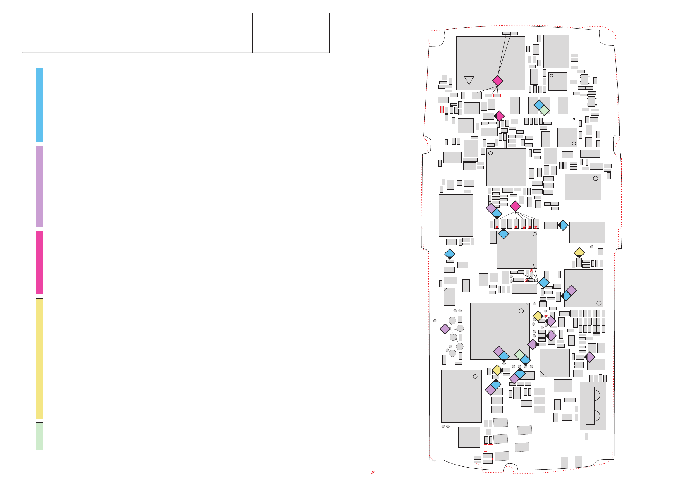
Baseband part 1
NSM-2/3
System Module RM7/RM7L
1(5)
Version 1.0 Approved
11.10.2000
NSM-3 differences in red
Measurepoint for GND-connected components
R723R723
C862C862
V801V801
C782C782
C788C788
C220C220
C864C864
R723R723
R807R807
5
C212C212
C212C212
C212C212
C760C760
L506L506
L503L503
C863C863
R758R758
C785C785
C805C805
VCOVCO
C802C802
3
R118R118
V350V350
C116C116
N220N220
J101
C758C758
R756R756
R757R757
C759C759
R711R711
N600N600
R755R755
R712R712
R805R805
G800G800
J102
J103
R211R211
ComboMemoryComboMemory
R751R751
R710R710
R801R801
V360V360
C206C206
C217C217
C209C209
C209C209
D210D210
C790C790
Z700Z700
C860C860
C783C783
T800T800
C804C804
R802R802
C801C801
C205C205
C205C205
M300M300
T700T700
R700R700
Z671Z671
C803C803
R704R704
C755C755
R284R284
R283R283
C799C799
C560C560
C550C550
Pwr. AmpPwr. Amp
C741C741
L504L504
V116V116
L752L752
R740R740
C704C704
L103L103
C286C286
R285R285
R284R284
R283R283
L284L284
L283L283
L505L505
C211C211
C281C281
N702N702
C742C742
T740T740
R975R975
C793C793
R800R800
11
C206C206
C218C218
C204C204
4
C285C285
R286R286
L284L284
L283L283
L751L751
C108C108
Mad2Mad2
1
C703C703
R741R741
C561C561
R974R974
C535C535
R564R564
R533R533
77
C152C152
C131C131
J226
11
C119C119
C213C213
1111
C754C754
C702C702
11
C541C541
C670C670
C747C747
R541R541
R744R744
C714C714
R791R791
R532R532
C746C746
R790R790
C557C557
R671R671
C792C792
R792R792
N505N505
HagarHagar
C562C562
C533C533
C564C564
R563R563
R565R565
C534C534
22
C153C153
C133C133
C106C106
C720C720
\\
C743C743
L553L553
R754R754
R763R763
C733C733
V730V730
C730C730
R732R732
R764R764
R763R763
R732R732
C630C630
L631L631
C631C631
L600L600
C600C600
C601C601
R510R510
C510C510
C531C531
C530C530
C532C532
R530R530
C540C540
C521C521
R546R546
C150C150
C154C154
C151C151
Z670Z670
C761C761
C614C614
C645C645
C163C163
C162C162
11
1
R730R730
R731R731
C731C731
T630T630
T600T600
C523C523
C522C522
C520C520
C513C513
C512C512
C511C511
C833C833
R833R833
C830C830
C129C129
C700C700
L510L510
R611R611
22
GSM+
GSM+
V800V800
R879R879
C615C615
R834R834
R830R830
R613R613
V904V904
C610C610
R610R610
C613C613
R643R643
C644C644
R645R645
V903V903
R640R640
C643C643
C640C640
C612C612
C611C611
R614R614
V907V907
Z600Z600
C620C620
VCTCXOVCTCXO
C621C621
V905V905
C642C642
L800L800
C834C834
C835C835
C832C832
C831C831
R831R831
C836C836
R832R832
G830G830
C165C165
Z620Z620
PCN
PCN
C879C879
88
CcontCcont
N100N100
R269R269
11
C248C248
L272L272
L271L271
C291C291
C292C292
N250N250
C261C261
C251C251
C259C259
C253C253
C257C257
C258C258
C257C257
C262C262
C275C275
C276C276
C263C263
C258C258
R267R267
C294C294
R268R268
C295C295
C261C261
C255C255
C296C296
C297C297
55
N401N401
C110C110
C406C406
R403R403
R404R404
N400N400
R270R270
C249C249
C102C102
R100R100
R128R128
C113C113
C132C132
C101C101
R154R154
C208C208
C102C102
C202C202
D200D200
2
99
C201C201
R101R101
R103R103
C127C127
33
2
J227
1010
R104R104
C128C128
B100B100
J228
C103C103
V104V104
C120C120
R122R122
22
R203R203
R216R216
R215R215
C203C203
R201R201
55
4444
C114C114
R125R125
R124R124
V104V104
C161C161
C140C140
R272R272
C268C268
V250V250
V252V252
R131R131
66
V100V100
C293C293
C400C400
COBBACOBBA
11
C266C266
C265C265
C247C247
C274C274
C276C276
C278C278
R252R252
V251V251
R274R274
R274R274
R260R260
C109C109
C104C104
R109R109
C276C276
C142C142
C405C405 C401C401
55
R120R120
R111R111
R205R205
R110R110
C107C107
C160C160
C121C121
V101V101
J252
55
R271R271
R277R277
C105C105
55
R258R258
N101N101
ChapsChaps
L104L104
F101F101
Page 2
nokia
Service & Analysis Center Europe
SACE CC Training Group
Internal audio faults
A: No audio from speaker
-. Check resistance of speaker (30 Ohm), change speaker if bend or soiled.
1. Check connection between speakerpads on PCB and C291/292, if not ok, check L271,272. Check for shorts to GND (>1M).
2. If fault persists, change COBBA (N250). Note that it is necessary to align RX / TX values and rewrite SIMlock-data after changing COBBA!
B: Microphone doesn't work
-. Check impedance of microphone (0,5-1kOhm), change if necessary.
3. Check mechanical condition of connector X280 (8850 only).
4. Check MicBias at L287, 2.4V on active microphone (see Layout). If not ok, check values around V250.
5. Check connection between L287 and C263 (470 Ohm).
6. If fault remains, change COBBA (N250). Note that it is necessary to align RX / TX values and rewrite SIMlock-data after changing COBBA!
Clock time problems
A: Clock time has to be corrected in short periods
1. Check amplitude and frequency of sleepclock oscillator at J228, should be 3.2Vpp squarewave at 32.768kHz.
If not ok, change B100 or check parts like R100, R102, R154 and C101, C102, C113.
B: Clock time is lost after removing battery
-. Check contact springs of battery, bend them if nessecary (see also NSM-2 service bulletin 20) or change RTC-battery.
Bending of springs should be always done, also with new batteries.
If fault persists, probably CCONT (N100) or CHAPS (N101) faulty. Note that you have to run energy management calibration after changing CCONT.
Not charging
A: Nothing happens if charger is connected
-. Check mechanical appearance of connector X110.
1. Check resistance of fuse F101.
2. Check resistance of Vcharge line to GND, value should be around 50kOhm. If not ok, check/change V100, C103/114.
3. Check / Change N101, N100.
B: “not charging" appears on LCD
-. Run energy management calibration. If it works without failuremessage, try to charge after calibration.
C: Battery temperature failed
4. Check X101, R120/122 or change CCONT (N100).
D: Battery size failed
5. Check X101, R120/122 or change CCONT (N100).
-. Battery voltage failed: Change CCONT (N100).
E: Charge current failed
6. Check / change R131, N101, N100.
-. Charge voltage failed:
7. Check Vcharge at voltage divider R103/104. If ok change CCONT (N100).
8. If not ok, check parts like X110, V100, F101, L104 or change N101.
SIMcard faults
A: Insert SIM card
-. Check X302 if bend or soiled, change if necessary.
1. Make sure that pads for SIMcard-reader on PCB are clean.
2. Check V104: Pin 1-SIMclock, pin 3-VSIM, pin-4 SIMdata, pin 5-SIMreset, also check R124, R125, R128.
3. Check resistance of SIMlines to GND, change V104, C127/128 if necessary.
4. Probably broken solderings under CCONT (N100). Remove CCONT if not underfilled, replace sparepart with µBGA rework machine and run energy management
calibration.
-.. If fault persists, probably Mad or PCB faulty.
B: SIMcard not accepted
-. Use Wintesla to open quick/RF info window, compare shown SIMlock-data with the listed entries of the respective productcode.
-. If shown SIMlock-data is the same as in the list, SIMlock is ok.
Probably Msin data field is closed to special Imsi number range can be opened only by operator! (refer to general SB 65).
-. If shown SIMlock-data is not the same as in the list or somehow corrupted rewrite SIMlock-data with Nokia security password or send phone to SACE.
-. If SIMlock is corrected or inactive but fault remains, probably broken solderings under COBBA (N250). Change COBBA, align RX / TX values and rewrite SIMlock-data
once more.
UI faults
A: Backlight failure (Also see measurement points on page 4)
1. Check voltage at pin 7 and 15 of N310 (see layout)- should be 2,8V when lights are on. If not ok, there could be a break between D200 and N310, or Mad is faulty
2. Check Vb 3.6V pin 1 of N310 and Vbb 2.8V pin 2 of N310. (See layout)
3. Check resistance of R310 and R311. (See layout)
4. Check Vb at LED´s V320-325 and V331-340. (See layout)
5. If keypad backlight is not bright enough, change resistor R311 (see layout) from39kOhm to 10kOhm (also see NSM 2 service bulletin 23).
B: Vibra failure
-. Check version of vibramotor, add support tape if necessary (see also NSM-3 service bulletin 11).
6. Check Vb 3.6V at V350.
7. Check Vb 3.6V pin 1 and Vbb 2.8V pin 2 of N310. (See layout)
8. Check vibra signal at pin 16 of N310. If not ok, check vibra_cnt at pin 19 of N310. (See layout)
If signal is ok at pin19, change N310, else there is a break between D200 and N310, or MAD is faulty.
C: Display failure
-. If line segments missing or no display function at all, check mechanical appearance of display, change it if necessary.
Copyright © 2000 Nokia Mobile Phones. All rights reserved
CONFIDENTIAL
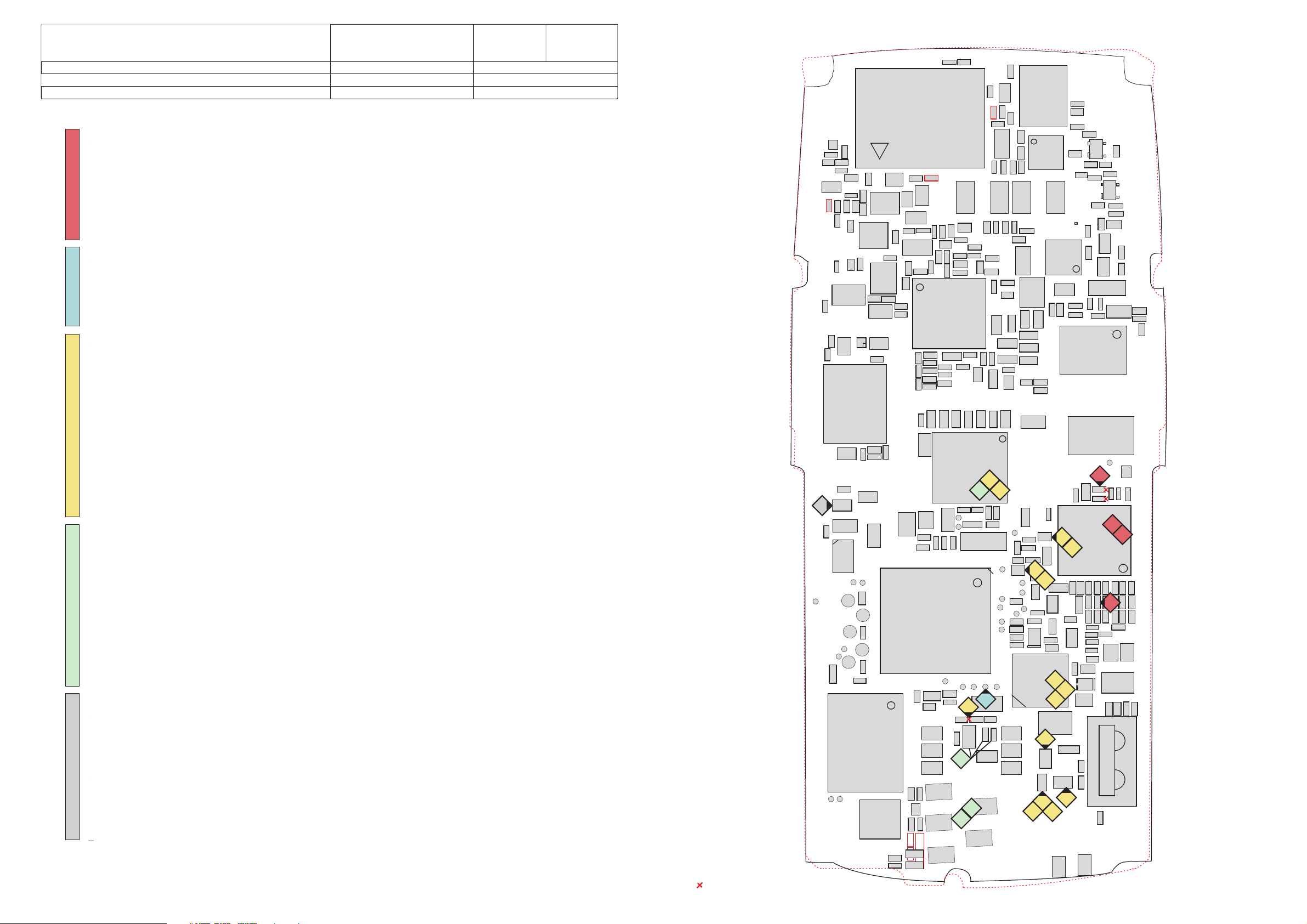
Baseband part 2
NSM-2/3
System Module RM7/RM7L
2(5)
Version 1.0 Approved
11.10.2000
NSM-3 differences in red
Measurepoint for GND-connected components
6
R723R723
C862C862
V801V801
C782C782
C788C788
C220C220
C754C754
C702C702
Pwr. AmpPwr. Amp
N702N702
R723R723
C760C760
L506L506
L503L503
C790C790
C758C758
R756R756
C864C864
R755R755
C863C863
R757R757
R758R758
C759C759
R711R711
C785C785
N600N600
R807R807
C805C805
VCOVCO
C802C802
R118R118
V350V350
C116C116
N220N220
C212C212
C212C212
C212C212
R211R211
R805R805
G800G800
R712R712
R801R801
V360V360
C206C206
C217C217
C209C209
C209C209
C755C755
R751R751
Z671Z671
R710R710
Z700Z700
R704R704
T700T700
C860C860
R700R700
C783C783
T800T800
C804C804
C803C803
R802R802
C801C801
C205C205
C205C205
ComboMemoryComboMemory
D210D210
C799C799
C560C560
C550C550
C741C741
L504L504
V116V116
L752L752
C704C704
R740R740
L103L103
L505L505
C211C211
C742C742
T740T740
R975R975
C793C793
R800R800
C206C206
C218C218
C204C204
L751L751
C703C703
C561C561
R974R974
C535C535
R564R564
R533R533
C108C108
C131C131
Mad2Mad2
C119C119
C213C213
C541C541
C670C670
C747C747
R541R541
R744R744
C714C714
R791R791
R532R532
C746C746
R790R790
R563R563
R565R565
C534C534
C106C106
C208C208
R671R671
N505N505
C533C533
C132C132
C557C557
C792C792
R792R792
C562C562
C564C564
C153C153
C133C133
CcontCcont
N100N100
R128R128
C113C113
R154R154
C102C102
R741R741
HagarHagar
C152C152
C202C202
D200D200
C201C201
R101R101
7
R103R103
R104R104
C128C128
C127C127
2
C286C286
C285C285
M300M300
R284R284
R283R283
R285R285
R284R284
R283R283
L284L284
L283L283
C281C281
R286R286
L284L284
L283L283
3
1
L631L631
R530R530
C154C154
4
B100B100
C103C103
V104V104
C720C720
\\
C743C743
L553L553
R754R754
R763R763
C761C761
C733C733
V730V730
C730C730
R732R732
C162C162
R764R764
R763R763
R732R732
R730R730
C731C731
C630C630
C631C631
L600L600
C600C600
C601C601
C520C520
R510R510
C510C510
C531C531
C530C530
C532C532
C540C540
C521C521
R546R546
C150C150
C151C151
3
6
C102C102
R100R100
C101C101
C120C120
R122R122
R203R203
R216R216
R215R215
C203C203
R201R201
1
C114C114
R125R125
R124R124
V104V104
Z670Z670
C700C700
L510L510
C614C614
Z620Z620
C645C645
C163C163
R731R731
T630T630
T600T600
C523C523
C522C522
C513C513
C512C512
C511C511
C833C833
R833R833
C830C830
C129C129
C140C140
R120R120
R111R111
R205R205
R110R110
C160C160
4
C121C121
V101V101
R271R271
R277R277
C105C105
N101N101
ChapsChaps
F101F101
1
8
R611R611
R613R613
V904V904
C615C615
C644C644
Z600Z600
PCN
PCN
GSM+
GSM+
V800V800
C879C879
R879R879
R834R834
R830R830
VCTCXOVCTCXO
C610C610
R610R610
C613C613
R643R643
R645R645
V903V903
R640R640
C643C643
C640C640
C612C612
C611C611
R614R614
V907V907
C620C620
C621C621
V905V905
C642C642
L800L800
C834C834
C835C835
C832C832
C831C831
R831R831
C836C836
R832R832
G830G830
C165C165
R269R269
1
C248C248
L272L272
L271L271
C291C291
C292C292
N250N250
C261C261
C251C251
2
6
C259C259
C253C253
C257C257
C258C258
C262C262
C275C275
C276C276
C263C263
R268R268
C257C257
5
C258C258
R267R267
C294C294
C295C295
C261C261
C255C255
C296C296
C297C297
N401N401
C110C110
C406C406
R403R403
R404R404
N400N400
C249C249
C161C161
COBBACOBBA
4
C107C107
5
C266C266
C265C265
5
C268C268
V250V250
V252V252
R258R258
R272R272
3
8
R131R131
C247C247
C274C274
C276C276
C278C278
C293C293
R252R252
V251V251
R274R274
R274R274
R260R260
C109C109
C104C104
R109R109
C276C276
6
C142C142
8
C400C400
L104L104
C405C405 C401C401
V100V100
8
2
R270R270
Page 3

nokia
Service & Analysis Center Europe
SACE CC Training Group
NO TX GSM900
1. Check 26MHz RFCLK at C830(700mVpp), frequency deviation <100Hz.
2. Check TxIQ signals at R541/546. If ok, go to 4.
3. Check Vbb 2,8V at C201and VCOBBA (2,8V) at C248, check COBBACLK at J252,
probably COBBA (N250) faulty or broken soldered.
4. Check 902MHz at T700 pin 4 and 6. If ok, go to 6.
5. Check supply voltages for HAGAR(N505) at C535 (1,35V), C550 (2,8V), C557 (2,8V), C560 (4,8V), C561 (2,8V), C562 (2,8V).
6. Check Sdata at J237, SCLK at R205,SENA at R206, TXC at C792.
7. Check TXP at pad of not assembled R745 (between R791/541).
8. Check frequency of G800 (SHF) at C788 (TX-Ch.60-3608MHz) if possible, otherwise you can check Vcc at C804(2,8V) and Vc at C803
which varies between 0,7-3,8V. If Vc =4,8V, the oscillator doesn`t work.
If values are OK but no TX signal at T700, pobably HAGAR(N505) is faulty or broken soldered.
9. Check 902MHz at N702,pin8. If not OK, check T700,Z700/671, V801.
10. Check 902MHz at L553 pin1. If not OK, check Vbatt at pin 3 and 6 of N702, also check TXV_GSM 2,8Vpp
squarewave at N702,pin2 and Vapc 1-1,6Vpp squarewave at N702,pin7 depending on TX powerlevel.
11. Check 902MHz at J600 (Antenna pad).If not, check L553 in/out, Z670 in/out, TXVGSM at R671.
NO TX GSM1800
1. Check 26MHz RFCLK at C830(700mVpp), frequency deviation <100Hz.
2. Check TxIQ signals at R541/546.If ok, go to 4.
3. Check Vbb 2,8V at C201and VCOBBA (2,8V) at C248, check COBBACLK at J252,
probably COBBA(N250) faulty or broken soldered.
4. Check 1747,8MHz at T740 pin 4 and 6. If ok, go to 6.
5. Check supply voltages for HAGAR(N505) at C535 (1,35V), C550 (2,8V), C557 (2,8V), C560 (4,8V), C561 (2,8V), C562 (2,8V).
6. Check Sdata at J237, SCLK at R205,SENA at R206, TXC at C792.
7. Check TXP at pad of not assembled R745 (between R791/541).
8. Check frequency of G800 at C788(TX-Ch.700-3495,6MHz) if possible, otherwise you can check Vcc at C804(2,8V) and Vc at C803
which varies between 0,7-3,8V. If Vc =4,8V, the oscillator doesn`t work.
If Values are OK but no TX signal at T740, pobably HAGAR(N505) is faulty or broken soldered.
9. Check 1747,8MHz at N702,pin8. If not OK, check T740, Z671, V801.
10. Check 1747,8 MHz at L553 pin3. If not OK, check Vbatt at pin 3 and 6 of N702, also check TXVDCS 2,8Vpp
squarewave at N702,pin1 and Vapc 1-1,6Vpp squarewave at N702,pin7 depending on TX powerlevel.
11. Check 1747,8MHz at J600 (Antenna pad).If not, check L553 in/out, Z670 in/out, TXVDCS at R670.
NO RX GSM900
1. Check 26MHz reference oscillator at C830, 700mVpp,frequency deviation < 100Hz
2. Check 947MHz at C645. If not ok check solderings of Z670, change if necessary and replace foam on sparepart.
(NSM 2 only)
3. Check 947MHz at C615. If not ok check/change Z620
4. Check 947MHz at C610. If not ok check values of LNA like Vlna 2,7V at R614 and LNA_G 0,7V at C611,change
V904/907 if necessary.
5. Check 947MHz at L600. If not ok check/change Z600, T600
6. Check RxIQ signal at R530. If not ok, check values at HAGAR(N505) supply voltages at
C560 (4,8V), C561 (2,8V), C562 (2,8V),
Check frequency of G800 at C788 (RX-Ch.60-3788MHz) if possible, otherwise you can check Vcc at C804(2,8V) and Vc at C803
which varies between 0,7-3,8V. If Vc =4,8V, the oscillator doesn`t work.
-. If all values are ok but no RxIQ signal at R530,
7. If signal at R530 is ok, but still no Rx-calibration possible,check values at COBBA(N250). Check Vbb 2,8V at C201 and
VCOBBA(2,8V) at C248, also check COBBACLK at J252, if values are ok, probably COBBA
solderings are broken.
NO RX GSM1800
1. Check 26MHz RFCLK at C830(700mVpp), frequency deviation <100Hz.
2. Check 1842,8MHz at C614. If not OK, check solderings of Z670, change if necessary and replace foam on
sparepart.(NSM-2 only).
3. Check 1842,8MHz at C644.If not OK, check/change Z620
heck 1842,8MHz at C640. If not ok check values of LNA like Vlna 2,7V at R614 and LNA_P 0,7V at
4. C
C642,change V903/905 if necessary.
5. Check 1842,8MHz at L631. If not ok check/change Z600, T630.
6. Check RxIQ signal at R530. If not ok check values at HAGAR(N505) like supply voltages at
C560 (4,8V), C561 (2,8V), C562 (2,8V), heck Sdata at J237, SCLK at R205,SENA at R206, RF_REF 1,2V at C534.
Check frequency of G800 at C788 (RX-Ch.700, 3685,6MHz)) if possible, otherwise you can check Vcc at C804(2,8V) and Vc at C803
which varies between 0,7-3,8V. If Vc =4,8V, the oscillator doesn`t work.
-. If all values are ok but no RxIQ signal at R530,
7. If signal at R530 is ok, but still no Rx-calibration possible,check values at COBBA(N250). Check Vbb 2,8V at C201 and
VCOBBA(2,8V) at C248, check also COBBACLK at J252, if values are ok, probably COBBA
solderings are broken.
CONFIDENTIAL
RF part
NSM-2/3
System Module RM7/RM7L
C535 (1,35V), C550 (2,8V), C557 (2,8V),
Sdata at J237, Sclk at R205 and Sena at R206, check RxRef 1,2V at C534,
pobably HAGAR(N505) is faulty or broken soldered.
C535 (1,35V), C550 (2,8V), C557 (2,8V),
c
pobably HAGAR(N505) is faulty or broken soldered.
3(5)
Version 1.0 Approved
11.10.2000
NSM-3 differences in red
C754C754
C702C702
8
7
9
R723R723
C760C760
R723R723
L506L506
C862C862
L503L503
C790C790
C758C758
V801V801
C864C864
C782C782
8
66
C788C788
8
R751R751
R756R756
R755R755
C863C863
R757R757
R710R710
R758R758
C759C759
R712R712
R711R711
C785C785
2
N600N600
C860C860
R807R807
R805R805
C805C805
66
G800G800
VCOVCO
1
Z700Z700
44
C783C783
T800T800
C804C804
99
T700T700
C755C755
Z671Z671
R704R704
44
R700R700
668
2
C799C799
6
4
C560C560
C550C550
Pwr. AmpPwr. Amp
L752L752
C741C741
R740R740
L504L504
8
6
6
6
6
C803C803
R801R801
R802R802
C802C802
C801C801
R118R118
V360V360
V350V350
C220C220
C116C116
C212C212
C212C212
C212C212
C205C205
C205C205
N220N220
C206C206
C217C217
C209C209
C209C209
R211R211
8
66
66
V116V116
ComboMemoryComboMemory
D210D210
M300M300
R284R284
R283R283
C704C704
L103L103
C286C286
R285R285
R284R284
R283R283
L284L284
L283L283
L505L505
8
C211C211
C281C281
N702N702
C742C742
T740T740
R975R975
C793C793
R800R800
R206R206
C218C218
C204C204
C285C285
R286R286
L284L284
L283L283
L751L751
Mad2Mad2
C703C703
C561C561
R974R974
C535C535
R564R564
R533R533
C108C108
C131C131
6
C119C119
C213C213
10
C670C670
6
R741R741
HagarHagar
66
C152C152
6
C202C202
66
6
3 4
C747C747
C714C714
R532R532
C746C746
R671R671
6
N505N505
66
C533C533
R563R563
R565R565
C534C534
66
C106C106
C132C132
6
C208C208
D200D200
33
77
77
C201C201
R101R101
22
C541C541
C102C102
R744R744
R790R790
C792C792
R792R792
6
C564C564
C133C133
CcontCcont
J237
33
R103R103
C127C127
5
R541R541
5
R128R128
22
R791R791
C557C557
55
C562C562
66
66 77
C153C153
N100N100
C113C113
R154R154
R104R104
C128C128
77
L631L631
R530R530
B100B100
C103C103
C531C531
C154C154
6
R124R124
V104V104
R732R732
C630C630
C631C631
R100R100
C101C101
7
C114C114
V104V104
1010
C743C743
R763R763
7
55
55
C530C530
C521C521
6
6
1010
\\
1
L553L553
3 5
R754R754
C733C733
V730V730
22
C730C730
R732R732
R764R764
R763R763
L600L600
C600C600
C601C601
R510R510
C510C510
C532C532
C540C540
C150C150
C151C151
C102C102
666
3
7
R125R125
R546R546
22
3
C720C720
C761C761
C162C162
C520C520
R203R203
R216R216
R215R215
C203C203
R201R201
7
R730R730
C731C731
22
R205R205
R205R205
C120C120
R122R122
2
C614C614
C645C645
C163C163
R731R731
C513C513
C512C512
C511C511
R833R833
T630T630
C523C523
C140C140
R111R111
R110R110
J252
C129C129
C160C160
R277R277
ChapsChaps
T600T600
C833C833
C121C121
V101V101
R271R271
C105C105
C522C522
C830C830
N101N101
Z670Z670
R120R120
F101F101
Z620Z620
L104L104
C107C107
R258R258
C161C161
R272R272
PCN
PCN
C879C879
C268C268
V250V250
V252V252
R131R131
V800V800
R879R879
11
V100V100
GSM+
GSM+
C293C293
C400C400
1111
R613R613
J600
V904V904
C610C610
44
R610R610
C613C613
R643R643
R645R645
V903V903
C615C615
1111
C700C700
L510L510
R611R611
33
C644C644
33
R640R640
C643C643
C640C640
4
C612C612
C611C611
R614R614
V907V907
Z600Z600
C620C620
R834R834
R830R830
VCTCXOVCTCXO
C621C621
V905V905
C642C642
L800L800
C834C834
C835C835
C832C832
C831C831
R831R831
C836C836
R832R832
G830G830
11
11
11
C165C165
7
R269R269
7
33
33
C248C248
L272L272
L271L271
C291C291
C292C292
N250N250
C261C261
C263C263
C251C251
C259C259
C253C253
C257C257
C258C258
C257C257
C262C262
C275C275
C276C276
C258C258
R267R267
C294C294
R268R268
C295C295
C261C261
C255C255
C296C296
C297C297
N401N401
R403R403
C406C406
C110C110
R404R404
C249C249
COBBACOBBA
C266C266
C265C265
C247C247
C274C274
C276C276
C278C278
R252R252
V251V251
R274R274
R274R274
C109C109
R260R260
C104C104
R109R109
C276C276
C142C142
N400N400
C405C405 C401C401
R270R270
Copyright © 2000 Nokia Mobile Phones. All rights reserved
Measurepoint for GND-connected components
Page 4

nokia
Service & Analysis Center Europe
SACE CC Training Group
66
C802C802
R118R118
V350V350
C
C116C116
2
2
20
20C
N
N
2
2
2
2
0
Vibra motor pinsVibra motor pins
C212C21
C
C
2
2
12C212
12C212
2
F
l
l
a
a
s
s
h
hF
R284R284
R283R283
Copyright © 2000 Nokia Mobile Phones. All rights reserved
0
C206C206
C
2
2
1
1
7
7C
C
C
C
C
2
2
2
2
09
09
09
09
R211R211
D2
D2
1
1
0
0
R2
R2
8
8
5
5
L284L284
L283L283
1
C
C
C
2
2
2
8
8
85C285
6
6
C2
C2
8
8
1
1
R
R
2
2
86
86
44
55
C7
C7
8
8
2
2
R8
R8
C
C
07
07
8
8
0
0
C
C
5
5
78
78
8
8
G
G
V
V
8
8
C
C
0
0
O
O
0
0
C
C
R
R
8
8
8
8
R802R802
0
0
0
0
3
3
1
1
C801C801
V360V360
0
0
0
0
5
5
5
5
C211C21
C213C213
V
V
1
1
1
1
6
6
C2
C2
C2
C2
C119C119
C204C204
M
M
20
20
ad2
ad2
0
0D
C201C201
R101R101
R103R103
R104R104
C
C
C
C
12
12
12
12
8
8
7
7
V104V104
DC & HS connector
DC & HS connector
5409095
5409095
SIM connector
SIM connector
5409117
5409117
R7
R7
2
2
3
3
R723
R723
L506L506
C862C862
L503L503
C758C758
V801V801
R756R756
C
C
R757R757
86
86
55
55
3
3
R7
C
C
58R7
58
7
7
5
5
9
9
R
R
R
R
7
7
C7
C7
7
7
1
1
1
1
8
8
1
1
2
2
5
5
N
6
6
0
0
0
0N
C860C860
R700R700
C783C783
R
R
8
8
0
0
5
5
T800T800
C804C804
20
20
6
6
C
C
10
10
8
8
C1
C
C
13
13
32
32C1
1
1
C
C
C
C
C
C
C218C218
20
20
1
1
2
2
02
02
0
0
8
8
2
2
D
C103C103
C114C114
R1
R
R
1
1
25
25R1
2
2
4
4
V
V
1
1
0
0
4
4
CONFIDENTIAL
Layout and connectors
NSM-2/3
System Module RM7/RM7L
33
22
11
1)SIMCLK
1)SIMCLK
2)RST
2)RST
3)VSIM
3)VSIM
4)GND
4)GND
5)VSIM
5)VSIM
6)DATA
6)DATA
P
P
wr
wr
.
.
Amp
C755C755
C741C741
r
r
a
a
C533C533
R122R122
R277R277
5
5
1
1C4
Amp
C704C704
L7
L7
L
L
5
5
75
75
1
1
2
2
L103L103
C
C
C
C
67
67
7
7
4
4
C742C742
7
7
0
0
T7
T7
C714C714
4
4
R
C
0
0
5
5
7
7
32
32R
4
4
R790R790
6C
6
R74
R
R
C792C792
6
6
1
1R74
71
71
R792R792
N
N
Ha
Ha
5
5
g
g
0
0
5
5
C
C562C562
5
5
31
31C
C564C564
R53
R53
C
C
5
5
0
0
21
21
C15
C1
C154C15
C
C
1
1
50
50C1
5
3C15
3
C
C
1
1
02
02
C1
C1
0
0
C4
0
0
5
4
1
1
C
C
1
1
40
40
R120R120
R111R111
R
20
20
R110R110
C
C
5R
5
1
1
0
0
7
7
C160C160
C120C120
C121C121
V1
V1
V
V
10
10
C268C268
0
0
1
1
1
1
V
2
2
5
5
0
0V
R271R271
V
C293C293
2
2
5
5
2V
2
V2
V2
5
5
1
1
R258R258
R272R272
C10
C10
4
4
R109R109
C276C276
C142C142
N4
C40
C40
0
0
5
5
0
0N4
R2
R2
7
7
0
0
C760C760
C
790C790
R7
R7
5
5
Z6
Z6
1
1
R
R
7
7
7
7
R710
R710
1
1
Z7
C
C
0
0
79
79
0Z7
0
9
9
R704R704
R
7
7
40
40R
T
T
L505L505
7
7
0
0
L5
L5
0
0
0
0
4
4
C560C560
C550C550
R
R
9
9
C561C561
7
7
5
5
R974R974
C
R563R563
7
7
9
9
C535C535
3
3C
R565R565
R8
R564R564
00
00R8
C534C534
R533R533
C
C
C
C
C
C
C
1
1
1
1
1
5
5
33C133
0
0
2
2
6
6
C
C
N
N
N1
N1
c
c
1
1
o
o
0
0
00
00
0
0
nt
nt
R1
R1
R128R128
C113C113
0
0
0
0
C101C101
R154R154
B110B110
R203
R203
R216R216
R215R215
C203C203
R201R201
N
N
Cha
Cha
N
1
1
1N
1
0
0
p
p
s
s
1
1
R
R
131
131
C400C400
L
L
1
1
0
0
4
4
F
F
F
1
1
1
1
0
0
01
01F
V100V100
1
1
V_BATTV_BATT
N
7
7
0
0
2
2N
C5
R541R541
41
41C5
R744R744
R791R791
C557C557
L631
L631
R
R
5
5
1
1
0
0
C510C510
C53
C53
0
0
C532C532
C540C540
R
R
546
546
C129C129
C
C
1
1
61
61
C26
C26
C26
C26
6
6
5
5
C2
76
76C2
C
C
27
27
8
8
R252R252
R274R274
R274R274
C109C109
C109C109
C110C11
C
C
4
4
0
0
0
6
6
B_TEMPB_TEMP
BSIBSI
C754C754
C702C702
R
R
R7
R7
R
76
76
732R73
6
6
4
4
2
3
3
C630C630
C631C631
L6
L6
C600C600
0
0
0
0
C601C601
C
5
5
C52
C52
2
2
2
2
3
3C
2
2
0
0
C513C513
C512C512
C511C511
C833C833
R833R833
C830C830
C
C
C
2
2
4
4
2
2
8
8
49
49C
C292C292
C
C
N25
OBB
OBB
0
0N25
A
A
C25
C25
C
C
C2
C2
C
C
261
261
2
2
5
5
4
4
9
9
3
3
7
7
C
C
C
C
C2
C
C
C
2
2
27
27
274C
274
2
2
62
62
76
76C2
6
6
3
3
5
5
R
R
C29
R
R
C
C
2
2
26
26
2
2
5
5
6
6
9
9
8
8
7
7
4
4C29
8
8
5
5
C261C261
C255C255
C29
C29
C
C
2
2
9
9
7
7
6
6
N401N4
01
R4
R4
R4
R4
0
0
0
0
4
4
3
3
\\
C7
L
L
5
5
4
4
53
53
3C7
3
R
7
7
5
5
C7
C7
4
4R
6
6
1
1
C733C733
C
C
6
6
V730V7
14
14
30
C6
C6
4
4
5
5
C7
C7
R
R
C
C
C
1
1
732
732
1
1
6
6
3
3
6
6
3
3C
0
0
2
2
R
R
7
7
30
30
R731R731
C731C731
P
GS
P
GS
C
C
T
6
6
N
N
M
3
3
0
0T
T
T
60
60
0
0
C
C
5
5
C291C291
C
258C
258
C
C
2
2
5
5
7
7
C
C
2
2
M
+
+
V800V800
C
R
879
8
8
879R
R834R834
79
79C
R830R830
V
V
C
C
8
8
T
T
30
30
C
C
X
X
O
O
C1
65C1
65
R269R269
L
L
L
C
C
2
2
2
2
2
2
7
7
7
7
51
51
2
2L
1
1
C2
C2
5
5
7
7
NSM-3 differences in red
300-399300-399
400-420400-420
200-220200-220
221-299221-299
400-900400-900
100-199100-199
Version 1.0 Approved
11.10.2000
BGNDBGND
Battery connector
Battery connector
5409093
5409093
Volume switchVolume switch
C
C
7
7
2
2
0
0
D
D
i
i
Z
Z
p
p
6
6
l
l
e
e
70
70
x
x
e
e
r
r
Z6
Z6
2
2
0
0
Z
600
600Z
C834
C834
5
5
R831R831
G
G
C700C700
L510L510
R611R611
R613R613
D
D
i
i
p
p
l
l
e
e
x
x
1
1C
C
6
6
20
20C
L800L800
C
C
83
83
6
6
1
1
C831C831
V9
V9
04
04
C615C615
R610R610
C613C613
R643R643
C644C644
R645R645
V903
V903
R640R640
C643C643
C640C640
C
C
6
6
1
1
2
2
C
R614R614
V90
V90
C
7
7
621
621C
V
V
9
9
C
05
05
642
642C
C832C832
C836C836
R
8
8
32
32R
UIUI
InfraredInfrared
BasebandBaseband
AudioAudio
RF-PartRF-Part
Power SupplyPower Supply
4(5)
C754C754
L505L505
C211C211
C281C281
N702N702
C742C742
T740T740
R975R975
C793C793
R800R800
R206R206
C218C218
C204C204
C285C285
R286R286
L284L284
L283L283
L751L751
C535C535
C108C108
MADMAD
C703C703
R741R741
C561C561
R974R974
R564R564
R533R533
C152C152
C131C131
J226
C119C119
C213C213
C702C702
C541C541
C670C670
C747C747
R541R541
R744R744
C714C714
R791R791
R532R532
C746C746
R790R790
C557C557
R671R671
C792C792
R792R792
N505N505
HAGARHAGAR
C562C562
C533C533
C564C564
R563R563
R565R565
C534C534
C106C106
C208C208
C202C202
R530R530
C153C153
C133C133
CCONTCCONT
N100N100
R128R128
C113C113
C132C132
J121
R154R154
J237
C102C102
D200D200
J223
C201C201
J227
R101R101
R103R103
R104R104
C128C128
C127C127
L631L631
C531C531
C154C154
B100B100
J122
J250
J251
J256
J253
J228
C103C103
R124R124
V104V104
R732R732
C630C630
C631C631
R100R100
C101C101
C114C114
V104V104
C743C743
R763R763
C733C733
R732R732
R763R763
L600L600
R510R510
C530C530
C521C521
C150C150
C102C102
J239
R125R125
\\
R754R754
V730V730
C730C730
C600C600
C601C601
C510C510
C532C532
J257
J252
J255
C720C720
C615C615
R834R834
R830R830
C700C700
L510L510
R611R611
Z600Z600
J600
R613R613
V904V904
C610C610
R610R610
C613C613
R643R643
C644C644
R645R645
V903V903
R640R640
C643C643
C640C640
C612C612
C611C611
R614R614
V907V907
C620C620
VCTCXOVCTCXO
C621C621
V905V905
C642C642
L800L800
C834C834
C835C835
C832C832
C831C831
R831R831
C836C836
R832R832
G830G830
L553L553
R764R764
Z670Z670
C761C761
C614C614
Z620Z620
C645C645
C163C163
C162C162
R730R730
R731R731
C731C731
C520C520
PCN
PCN
GSM+
T630T630
C523C523
GSM+
T600T600
V800V800
C879C879
R879R879
C522C522
C513C513
C512C512
C511C511
C540C540
R546R546
C833C833
R833R833
C830C830
C151C151
C120C120
R122R122
R203R203
R216R216
R215R215
C203C203
R201R201
J104
R205R205
C129C129
C140C140
R111R111
R110R110
C160C160
J254
R277R277
ChapsChaps
C121C121
V101V101
R271R271
C105C105
C161C161
R120R120
C107C107
C268C268
V250V250
V252V252
C293C293
R258R258
R272R272
N101N101
C165C165
C291C291
C292C292
N250N250
C261C261
R269R269
L272L272
L271L271
C251C251
C259C259
C253C253
C257C257
C258C258
C257C257
C262C262
C275C275
C276C276
C263C263
C258C258
R267R267
C294C294
R268R268
C295C295
C261C261
C255C255
C296C296
C297C297
N401N401
U53
C248C248
C249C249
COBBACOBBA
C266C266
C265C265
C247C247
C274C274
C276C276
C278C278
R252R252
V251V251
R274R274
R274R274
R260R260
C109C109
C104C104
R109R109
C276C276
C110C110
C142C142
R131R131
C400C400
L104L104
F101F101
C405C405 C401C401
V100V100
C406C406
R403R403
R404R404
N400N400
R270R270
C342C342C342C342
C330C330C330C330
B301B301
C310C310
99
33
V325V325
V321V321
V323V323
NSM-3
N301N301N301N301
11
N310N310N310N310
C331C331C331C331
22
55
R311R311R311R311
R351R351R351R351
R310R310R310R310
R350R350R350R350
R353R353R353R353
R352R352R352R352
V324V324V324V324
R723R723
C760C760
R723R723
L506L506
V320V320
V324V324
V322V322
V336V336V333V333
C862C862
V801V801
C782C782
L503L503
C790C790
C758C758
R751R751
R756R756
C864C864
R755R755
C863C863
R757R757
R710R710
R758R758
C759C759
R712R712
R711R711
C785C785
N600N600
C860C860
Z700Z700
C783C783
T700T700
R700R700
Z671Z671
R704R704
C755C755
C799C799
C560C560
C550C550
Pwr. AmpPwr. Amp
C704C704
L752L752
L103L103
C741C741
R740R740
L504L504
4
R807R807
R805R805
C805C805
C802C802
N220N220
J110
ComboMemoryComboMemory
T800T800
C804C804
G800G800
C803C803
R801R801
R802R802
C801C801
V360V360
V116V116
C205C205
C205C205
J242
C206C206
C217C217
J101
C209C209
C209C209
R211R211
D210D210
C286C286
R284R284
R283R283
R285R285
R284R284
R283R283
L284L284
L283L283
M300M300
V335V335V332V332
C788C788
VCOVCO
C
C
6
6
1
1
0
0
V331V331
B301B301
C310C310
V325V325
V321V321
V323V323
NSM-2
V334V334
5
L287L287
4
C287C287
R287R287
R118R118
C342C342C342C342
C330C330C330C330
99
33
N301N301N301N301
11
N310N310N310N310
C331C331C331C331
22
55
R311R311R311R311
R351R351R351R351
R310R310R310R310
R350R350R350R350
R353R353R353R353
R352R352R352R352
V324V324V324V324
V350V350
C220C220
C116C116
J241
J103
J230
V320V320
V322V322
J102
J235
J120
C212C212
C212C212
C212C212
4
V333V333
V337V337
V332V332
V340V340
V331V331
S300S300
V336V336
V338V338
V335V335
J236
V339V339
V334V334
5
R287R287
L287L287
C287C287
4
J260
X280X280
Page 5

nokia
Service & Analysis Center Europe
SACE CC Training Group
Z670Z670
C720C720
L553L553
\\
C743C743
C754C754
C702C702
L510L510
R611R611
C700C700
C761C761
R754R754
C733C733
N702N702
Pwr. AmpPwr. Amp
C614C614
R613R613
V730V730
R723R723
C610C610
V904V904
C615C615
Z620Z620
C645C645
C760C760
R723R723
R610R610
C613C613
C163C163
C162C162
C730C730
R732R732
L506L506
C862C862
C790C790
L503L503
CONFIDENTIAL
Measurements
NSM-2/3
Version 1.0 Approved
11.10.2000
5(5)
System Module RM7/RM7L
R832R832
C836C836
C832C832
C621C621
R640R640
C640C640
V903V903
R643R643
R645R645
C644C644
R614R614
V907V907
C612C612
C643C643
C611C611
V905V905
C620C620
Z600Z600
GSM+
GSM+
PCN
PCN
T600T600
C642C642
T630T630
R731R731
C731C731
R730R730
R764R764
R763R763
R732R732
R791R791
R541R541
R744R744
C541C541
C746C746
C747C747
C714C714
R532R532
C670C670
L751L751
C704C704
L752L752
C755C755
Z671Z671
R751R751
R710R710
R755R755
R756R756
R757R757
C758C758
C863C863
R758R758
L103L103
C759C759
C742C742
C799C799
Z700Z700
T740T740
C741C741
C630C630
C557C557
R790R790
R704R704
R712R712
R711R711
L631L631
C792C792
R671R671
R741R741
R740R740
C785C785
C631C631
R792R792
L505L505
T700T700
C600C600
L600L600
L504L504
V801V801
L800L800
V800V800
N600N600
C835C835
C834C834
R834R834
R879R879
C879C879
C601C601
N505N505
HagarHagar
C560C560
R700R700
C860C860
C782C782
C831C831
C522C522
C523C523
C520C520
R510R510
C550C550
C783C783
R831R831
R830R830
G830G830
VCTCXOVCTCXO
C513C513
C512C512
C510C510
C530C530
C531C531
C562C562
C533C533
C561C561
R975R975
T800T800
R805R805
C805C805
R807R807
C788C788
C165C165
C830C830
C833C833
C511C511
R833R833
R546R546
C540C540
C532C532
C521C521
R530R530
C564C564
R565R565
C534C534
R563R563
R564R564
R533R533
R974R974
C535C535
R800R800
C793C793
C804C804
C151C151
C150C150
C154C154
C153C153
C133C133
C106C106
C152C152
C206C206
C129C129
N100N100
CcontCcont
C108C108
C803C803
R802R802
C801C801
R801R801
G800G800
VCOVCO
C802C802
R269R269
C251C251
L271L271
L272L272
C248C248
C249C249
C291C291
C292C292
N250N250
COBBACOBBA
C161C161
C140C140
C102C102
R100R100
C113C113
R128R128
C132C132
C131C131
V116V116
V360V360
R118R118
V350V350
C101C101
R154R154
C205C205
C205C205
C116C116
C220C220
R120R120
R111R111
R205R205
C102C102
C208C208
C202C202
C218C218
C107C107
R110R110
B110B110
C204C204
N220N220
C257C257
C258C258
C253C253
C259C259
C261C261
C247C247
C266C266
C265C265
C121C121
C160C160
C120C120
R122R122
C268C268
V101V101
V101V101
C257C257
C206C206
C275C275
C276C276
C262C262
C263C263
C274C274
C276C276
V250V250
R203R203
C258C258
C294C294
C295C295
R267R267
R268R268
C278C278
C293C293
V252V252
R271R271
R277R277
R216R216
D200D200
Mad2Mad2
C261C261
R252R252
C105C105
C217C217
C255C255
R274R274
V251V251
R215R215
C203C203
C297C297
C296C296
R274R274
R258R258
R272R272
R201R201
C109C109
C109C109
R109R109
C104C104
N1N1
N101N101
ChapsChaps
C209C209
C209C209
C212C212
C212C212
C212C212
N401N401
R211R211
R403R403
R404R404
C406C406
C110C110
C276C276
C142C142
R131R131
C114C114
C103C103
R104R104
R103R103
C201C201
R101R101
C213C213
C119C119
C211C211
ComboMemoryComboMemory
R125R125
R124R124
C128C128
C127C127
D210D210
N400N400
C405C405 C401C401
C400C400
L104L104
V104V104
V104V104
F101F101
F101F101
R270R270
V100V100
C281C281
R286R286
R285R285
L283L283
L284L284
R283R283
R284R284
C285C285
C286C286
M300M300
Copyright © 2000 Nokia Mobile Phones. All rights reserved
 Loading...