

Page 1

Customer Care Solutions
Technical Documentation
3-Service Software Instructions
Issue 1 11/2004 COMPANY CONFIDENTIAL 1
Copyright © 2004 Nokia. All Rights Reserved.
Page 2

CCS Technical Documentation
RM-12
[This page intentionally blank]
2 COMPANY CONFIDENTIAL Issue 1 11/2004
Copyright © 2004 Nokia. All Rights Reserved.
Page 3

Quick Guide for Phoenix Service SW Installation ........................................................3
Phoenix Installation Steps in Brief .............................................................................. 3
Phoenix Service SW ......................................................................................................3
Before Installation ....................................................................................................... 3
Startup .........................................................................................................................5
Dongle Driver Installation and Version Check ........................................................... 6
First Time Installation of Phoenix .............................................................................. 7
Update Installation of Phoenix .................................................................................. 10
How to Uninstall Phoenix ......................................................................................... 11
Data Package for Phoenix (Product-specific) ..............................................................13
Before installation ..................................................................................................... 13
Installation of Phoenix Data Package (Product-specific) .........................................14
How to Uninstall Data Package ................................................................................17
How to Manage Connections ....................................................................................17
Manual Settings ...................................................................................................... 19
How to Update Flash Support Files for FPS-8* and FLS-4S* .................................... 21
Before Installation ..................................................................................................... 21
Installing the Flash Support Files .............................................................................. 21
How to Update The FPS-8* Flash Prommer SW .....................................................24
FPS-8 Activation and Deactivation .............................................................................26
Activation ..................................................................................................................26
Deactivation .............................................................................................................. 28
JBV-1 Docking Station SW .........................................................................................29
Before Installation ..................................................................................................... 29
Installing SW Needed for the JBV-1 SW Update ..................................................... 30
Updating the JBV-1 Docking Station Software ........................................................ 34
Receiver tuning: Quick Guide for Tuning With Phoenix ............................................ 37
General remarks ........................................................................................................ 37
Service Tool Concept for RF Tuning Operations ........................................................38
Autotuning ...................................................................................................................39
Set Loss ................................................................................................................... 40
Environment ..............................................................................................................41
Protection ................................................................................................................42
Receiver Manual Tuning ............................................................................................. 42
RX Channel Select Filter Calibration ....................................................................... 42
RX Calibration .......................................................................................................... 44
RX Band Filter Response Compensation .................................................................. 48
Rx Am Suppression ..................................................................................................54
RX DTOS balance calibration .................................................................................. 58
Transmitter Manual Tuning ......................................................................................... 61
TX Power Level Tuning ...........................................................................................61
Tuning at EDGE900 ............................................................................................... 64
Tuning at GSM1800 band ...................................................................................... 65
Tuning at EDGE1800 ............................................................................................. 66
Tuning at GSM1900 band ...................................................................................... 67
Tuning at EDGE1900 ............................................................................................. 69
TX I/Q Tuning ..........................................................................................................71
Tuning at GSM/EDGE1800 band ........................................................................... 74
Tuning at GSM/EDGE1900 band ........................................................................... 75
Service Tool Concept For Baseband Tuning Operations ............................................76
Page 4

Service Concept for RM-12* Baseband tunings ....................................................... 77
Baseband Tuning operations ....................................................................................... 78
Energy Management Tuning ..................................................................................... 78
Flashing Setup Instructions ......................................................................................... 81
POS (Point of Sale) Flash Concept ........................................................................... 81
Flash Concept with Flashing adapter ........................................................................82
Module Jig Concept ..................................................................................................83
JBV-1 Flash Concept ................................................................................................84
Service Concept ........................................................................................................ 85
Parallel Flash concept ............................................................................................... 86
Page 5
RM-12
CCS Technical Documentation
Quick Guide for Phoenix Service SW Installation
2004
Phoenix Installation Steps in Brief
Note! The Phoenix screenshots in this document are examples. Always use an up to date version of
Phoenix software and data package.
Note! The service tools concept picture in this document are examples.
DCT-4 generation Test and Service Software is called “Phoenix”
These are the basic steps to install the Phoenix
• Install the Phoenix Service SW
• Install the Data Package for Phoenix (product specific data and flash update package)
• Manage connection settings (depends on the tools you are using)
• Update FPS-8 SW (if you use FPS-8)
• Activate FPS-8
• Update JBV-1 Docking Station SW (only when needed)
The flash update files are delivered with then Phoenix Data Package so unless you want to use
certain version of this package, separate installation package is not needed anymore. If you
want to use it, it should be installed after connection management, before FPS-8 update.
Please refer to Service Manual and Technical Bulletins for more information concerning phone
model specific service tools and equipment setup.
Issue 1 11/2004 COMPANY CONFIDENTIAL 3
Copyright © 2004 Nokia. All Rights Reserved.
Page 6
CCS Technical Documentation
Phoenix Service SW
Before Installation
• Check that a Dongle is attached to the parallel port of your computer.
• Download the installation package (e.g. phoenix_service_sw_a7_2003_9_2_3.exe) to
your computer (e.g. C:\TEMP)
• Close all other programs
RM-12
• Run the application file (e.g.
phoenix_service_sw_a7_2003_9_2_3.exe) and follow
instructions on the screen
• Administrator rights may be required to be able to install Phoenix depending on
the Operating System
• If the dongle driver is installed or updated, you need to reboot your PC before the
installation can continue.
• If uninstalling or rebooting is needed at any point, you will be prompted by the
Install Shield program.
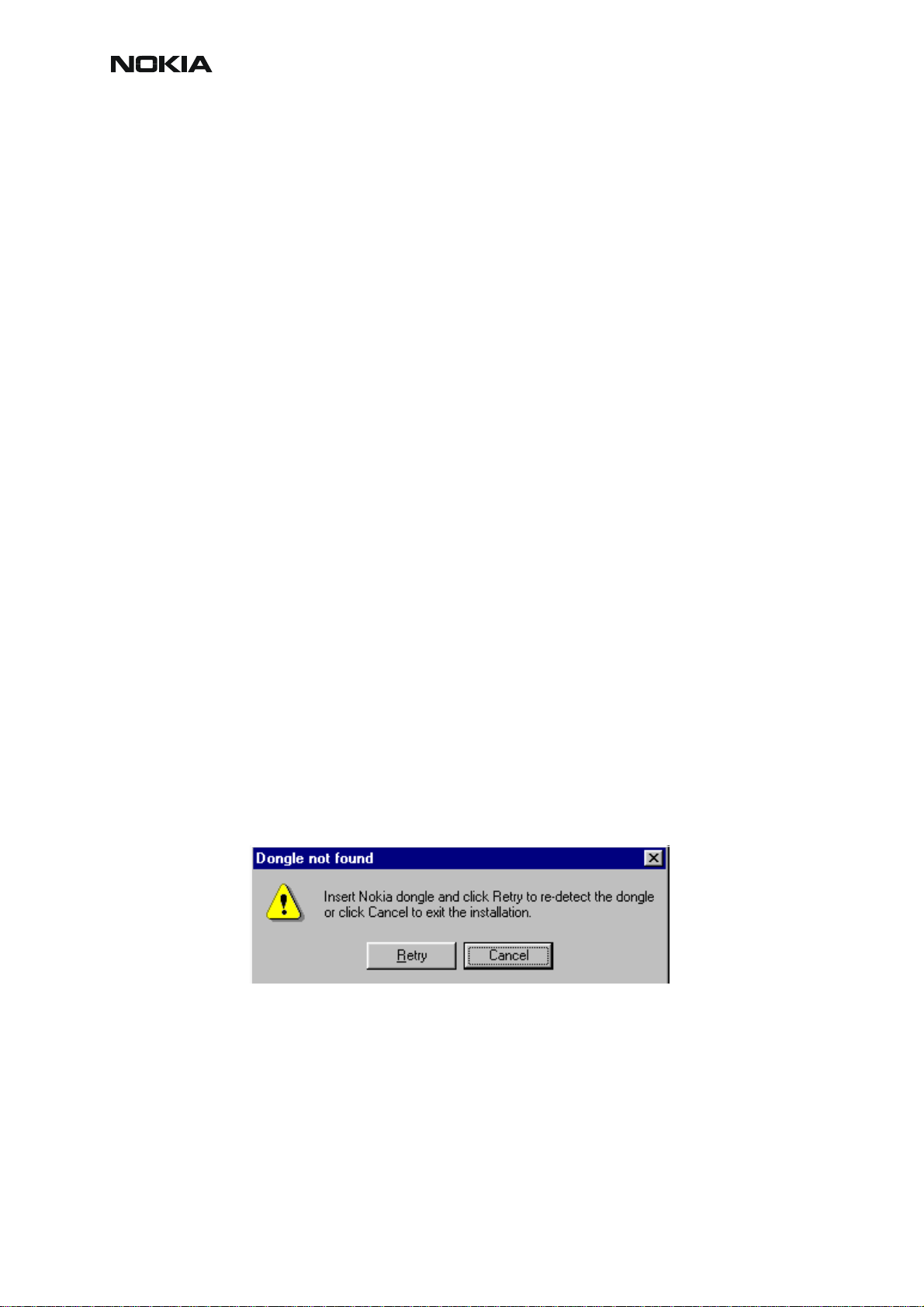
If at any point during installation you get this message, Dongle is not found and installation
can´t continue.
Possible reasons may be defective or too old PKD-1Dongle (five digit serial number Dongle
when used with FPS-8 Prommer) or that the FLS-4S POS Flash Dongle is defective or powe r
to it is not supplied by external charger.
Check the COM /parallel ports used first! After correcting the problem Installation can be restarted.
4 COMPANY CONFIDENTIAL Issue 1 11/2004
Copyright © 2004 Nokia. All Rights Reserved.
Page 7
RM-12
CCS Technical Documentation
Startup
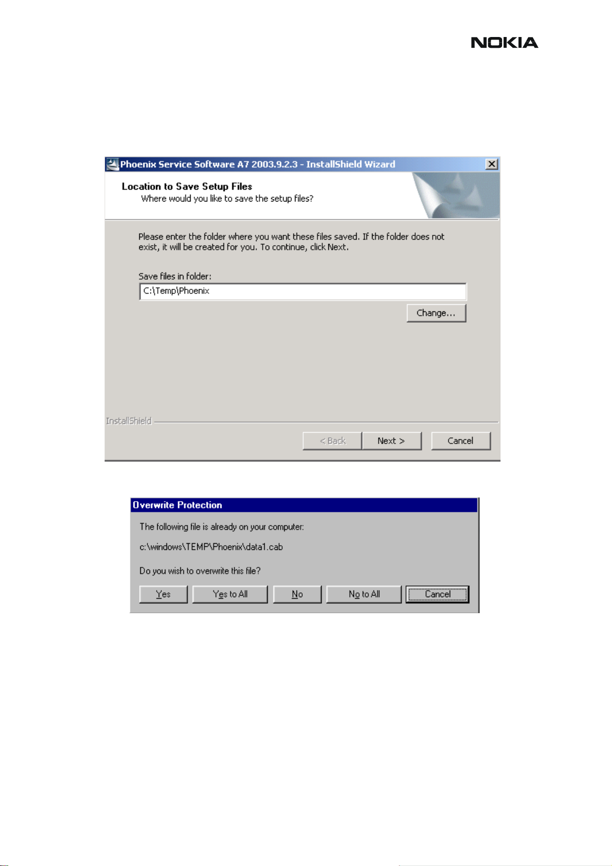
Run the phoenix_service_sw_a7_2003_9_2_3.exe to start installation.
When you choose “Next” the files needed for installation will be extracted. Kindly wait.
If the setup files are already extracted (left in the file system from previous installation) following
dialog appears. Always click "Yes to All" to overwrite the existing setup files.
Issue 1 11/2004 COMPANY CONFIDENTIAL 5
Copyright © 2004 Nokia. All Rights Reserved.
Page 8
RM-12
CCS Technical Documentation
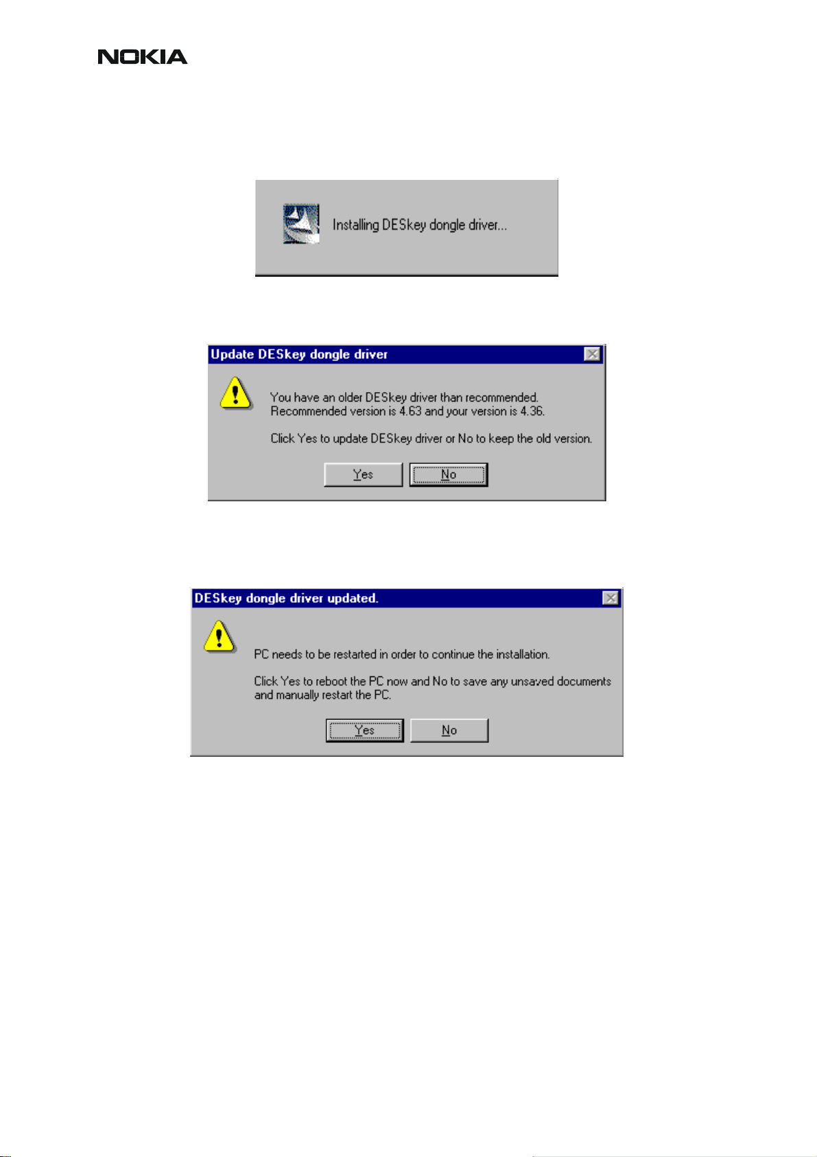
Dongle Driver Installation and Version Check
If there is no previously installed Dongle driver, installation will take place...
If the Dongle driver is installed and it is older than the latest supported version, the latest version will be installed when you choose “Yes”. The latest version is always included in the latest
Phoenix installation package.
PC needs to be rebooted before installation can continue. Click "Yes" to reboot the PC.
Setup is restarted automatically after reboot.
6 COMPANY CONFIDENTIAL Issue 1 11/2004
Copyright © 2004 Nokia. All Rights Reserved.
Page 9
RM-12
CCS Technical Documentation
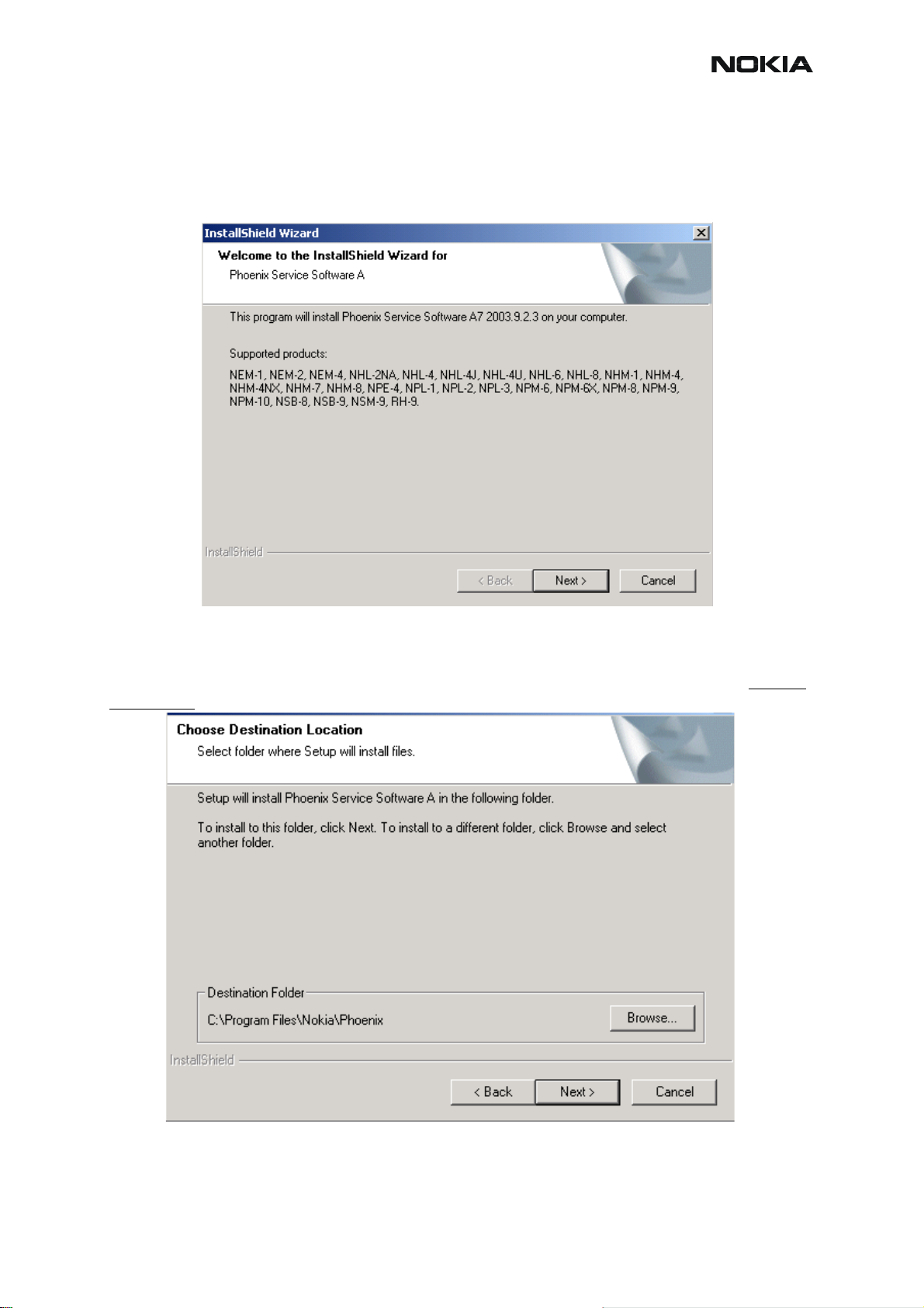
First Time Installation of Phoenix
After Dongle driver installation / update (if needed) installation continues from this step.
Click "Next" in Welcome dialog to continue.
Choose the destination folder, it is recommended to use the default folder C:\Program-
Files\Nokia\Phoenix.
Choose “Next” to continue. You may choose another location by selecting “Browse” (not recommended)
Setup copies the components, please wait.
Issue 1 11/2004 COMPANY CONFIDENTIAL 7
Copyright © 2004 Nokia. All Rights Reserved.
Page 10

CCS Technical Documentation
Progress of the setup is shown. Please wait…
RM-12
If restarting of your computer is needed the Install Shield Wizard will tell you about it.
Select "Yes..." to reboot the PC immediatelly and "No..." to reboot the PC manually.
Note that Phoenix doesn't work, if components are not registered
. Click "Finish" to continue.
After the reboot components are registered and Phoenix is ready for use.
8 COMPANY CONFIDENTIAL Issue 1 11/2004
Copyright © 2004 Nokia. All Rights Reserved.
Page 11
RM-12
CCS Technical Documentation
If reboot is not needed components are registered after copying them.
If restarting of your computer is not needed, Click "Finish" to exit the setup.
Phoenix is now ready for use.
Now the installation of Phoenix Service SW is ready and it can be used after:
• Installing Phone model specific Phone Data Package for Phoenix
• Configuring the connections
• Updating the Flash Update Package files used with FPS-8* and FLS-4S* tools
Issue 1 11/2004 COMPANY CONFIDENTIAL 9
Copyright © 2004 Nokia. All Rights Reserved.
Page 12
RM-12
CCS Technical Documentation
Update Installation of Phoenix
If you already have the Phoenix Service SW installed on your computer, sooner or later there
will be need to update it when new versions are released.
Please note that very often the Phoenix Service SW and the Phone Specific Data Package for
Phoenix come in pairs, meaning that certain version of Phoenix can only be used with certain
version of Data Package. Always use the latest available versions of both. Instructions can be
found in phone model specific Technical Bulletins.
To update the Phoenix you need to take exactly the same steps as when installing it for the first
time.
• Download the installation package to your computer hard disk
• Close all other programs
• Run the application file (e.g. phoenix_service_sw_a7_2003_9_2_3.exe)
• Dongle driver version will be checked and if need be, updated
• After reboot installation starts automatically
• Newer version of Phoenix will be installed
When you update the Phoenix from old to new version (e.g. update from 2003_9_2_3 to
2003_9_2_5), the update usually takes place automatically without uninstallation. However,
uninstallation of the older version of Phoenix is sometimes required, before the new version can
be installed.
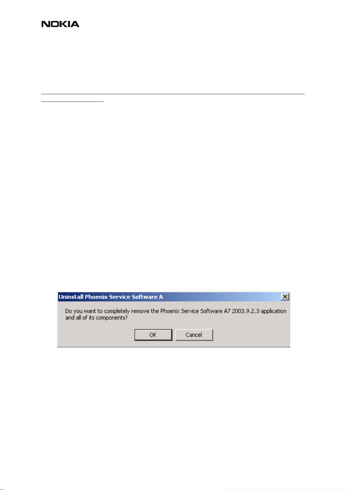
If you try update the Phoenix with the same version that you already h ave you are asked if you
want to uninstall the version of Phoenix you have on your PC. Answer “OK” to uninstall Phoenix, “Cancel” if you don’t want to uninstall.
If you try to install an older version (e.g. downgrade from 2003_9_2_3 to 2003_9_1_2) installation will be interrupted.
Always follow the instructions on the screen.
10 COMPANY CONFIDENTIAL Issue 1 11/2004
Copyright © 2004 Nokia. All Rights Reserved.
Page 13
RM-12
CCS Technical Documentation
How to Uninstall Phoenix
Uninstallation can be done manually from Windows Control Panel - Add / Remove Programs.
Choose “Phoenix Service Software” and click "Add/Remove".
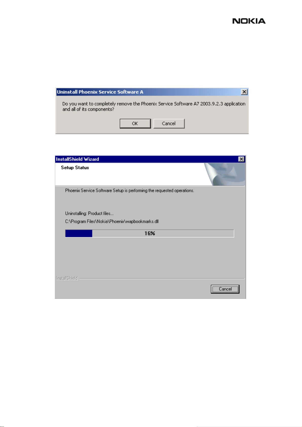
Choose “OK” to uninstall
Progress of the uninstallation is shown.
Issue 1 11/2004 COMPANY CONFIDENTIAL 11
Copyright © 2004 Nokia. All Rights Reserved.
Page 14
CCS Technical Documentation
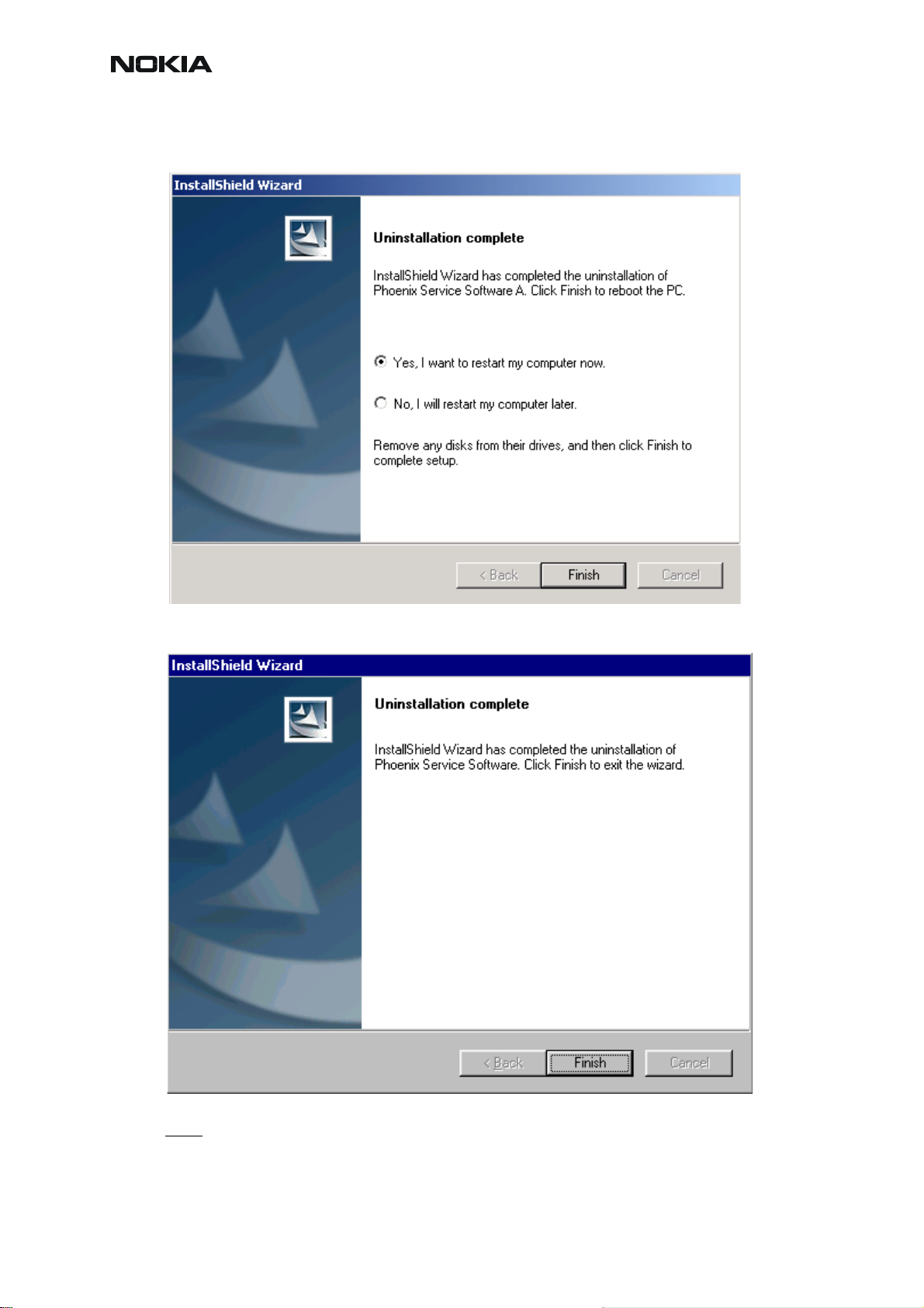
You may have to reboot the PC after uninstallation.
RM-12
If restarting is not needed, the following dialog will appear:
Note! If you have different product packages installed, components are uninstalled only if they are not
included in other product packages.
12 COMPANY CONFIDENTIAL Issue 1 11/2004
Copyright © 2004 Nokia. All Rights Reserved.
Page 15
RM-12
CCS Technical Documentation
Data Package for Phoenix (Product-specific)
Before installation
Product Data Package contains all product specific data to make the Phoenix Service Software
and tools usable with a certain phone model.
It also includes the latest version of flash update package for FLS-4S, FPS-8 and FPS-10. They
are also included in the latest Phoenix installation.
• Check that the Dongle is attached to the parallel port of your computer.
• Install Phoenix Service SW
• Download the latest installation package (e.g., RM-12_dp_v1.0_sw3.02.exe) to
your computer (e.g. C:\TEMP)
• Close all other programs
• Run the application file (e.g., RM-12_dp_v1.0_sw3.02.exe) and follow instructions
on the screen
If you already have the Phoenix Service SW installed on your computer, sooner or later there
will be need to update it when new versions are released.
Please note that very often the Phoenix Service SW and the Phone Specific Data Package for
Phoenix come in pairs, meaning that certain version of Phoenix can only be used with certain
version of Data Package. Always use the latest available versions of both. Instructions can be
found in phone model specific Technical Bulletins.
Issue 1 11/2004 COMPANY CONFIDENTIAL 13
Copyright © 2004 Nokia. All Rights Reserved.
Page 16
RM-12
CCS Technical Documentation
Installation of Phoenix Data Package (Product-specific)
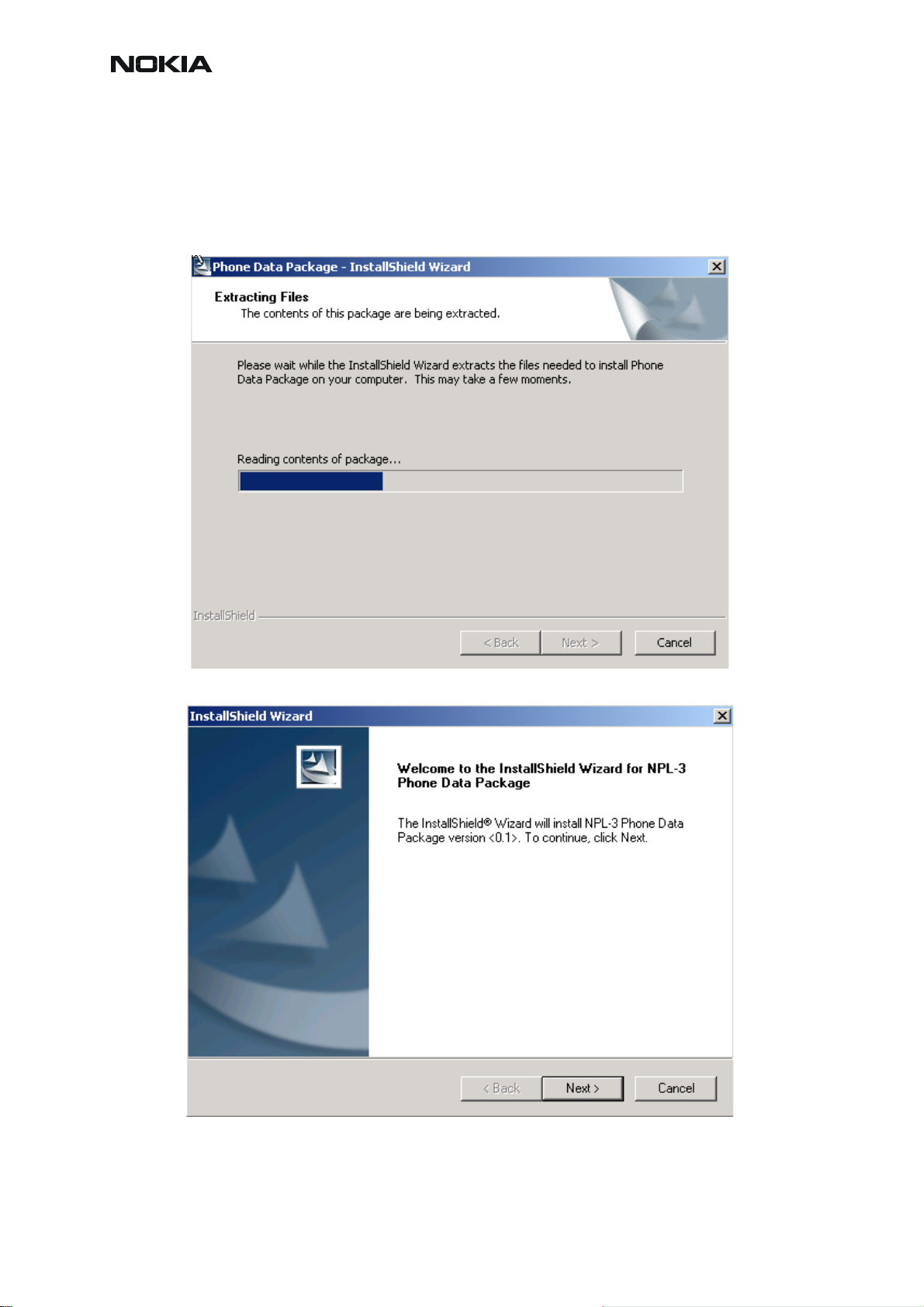
Run the the latest Phoenix Data Package (e.g. RM-12_dp_v1.0_sw3.02.exe) to start installa-
tion.
When you choose “Next” the files needed for installation will be extracted. Please wait…
Choose “Next” to continue.
From this view you can see the contents of the Data Package.
Read the text carefully.
14 COMPANY CONFIDENTIAL Issue 1 11/2004
Copyright © 2004 Nokia. All Rights Reserved.
Page 17
RM-12
CCS Technical Documentation
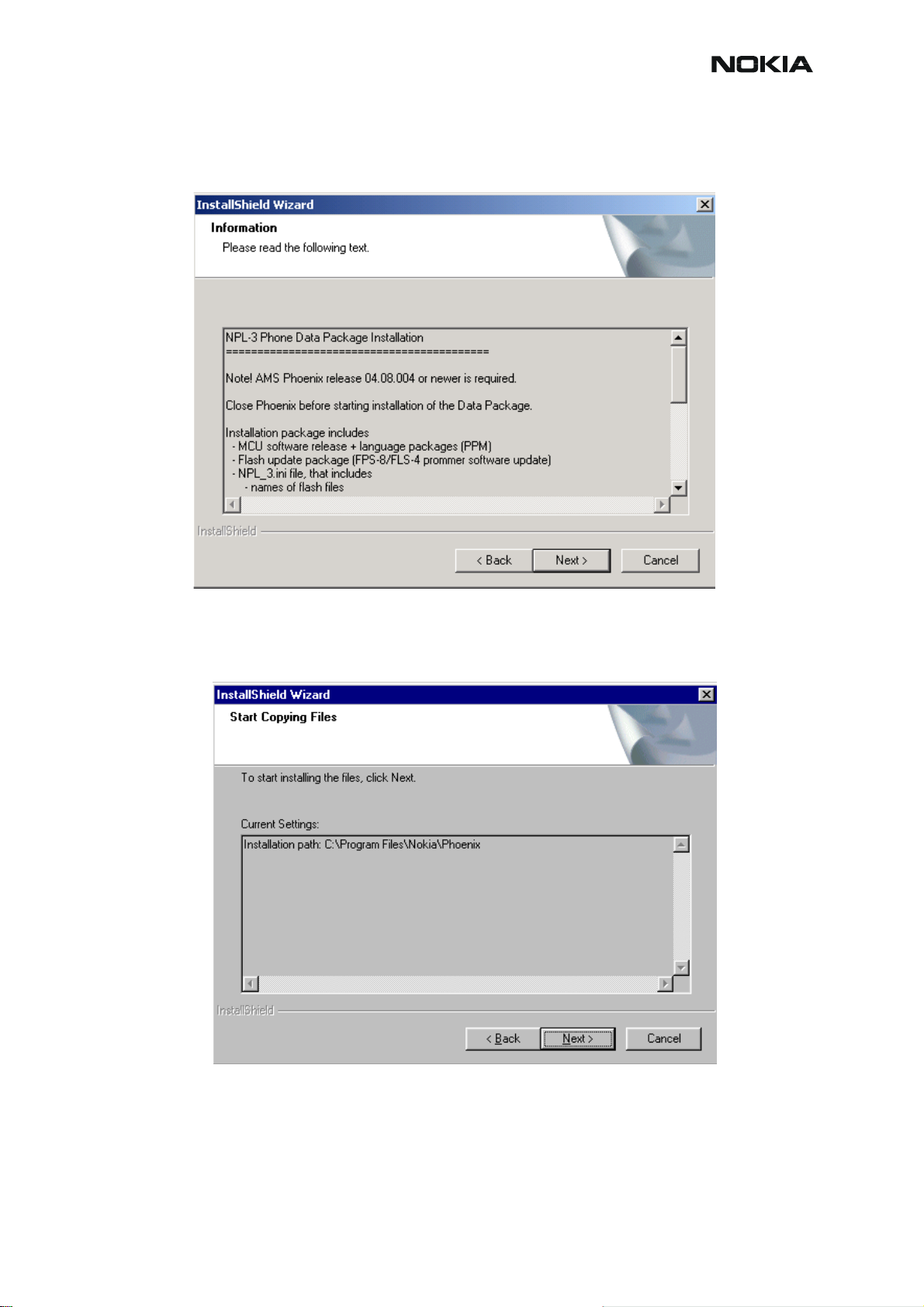
There should be information about the Phoenix version needed with this data package. Choose
“Next”.
Confirm location and choose “Next” to continue.
Install Shield checks where the Phoenix application is installed and the directory is shown.
Choose “Next” to continue.
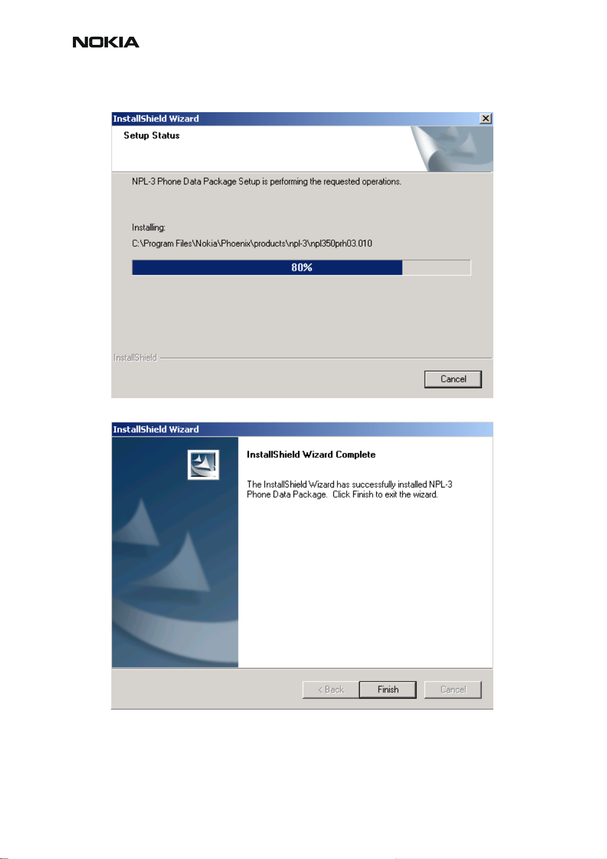
Phone model specific files will be installed... please wait.
Issue 1 11/2004 COMPANY CONFIDENTIAL 15
Copyright © 2004 Nokia. All Rights Reserved.
Page 18
CCS Technical Documentation
RM-12
Choose “Finish” to complete installation.
You now have all phone model specific files installed in your Phoenix Service SW.
16 COMPANY CONFIDENTIAL Issue 1 11/2004
Copyright © 2004 Nokia. All Rights Reserved.
Page 19
RM-12
CCS Technical Documentation
How to Uninstall Data Package
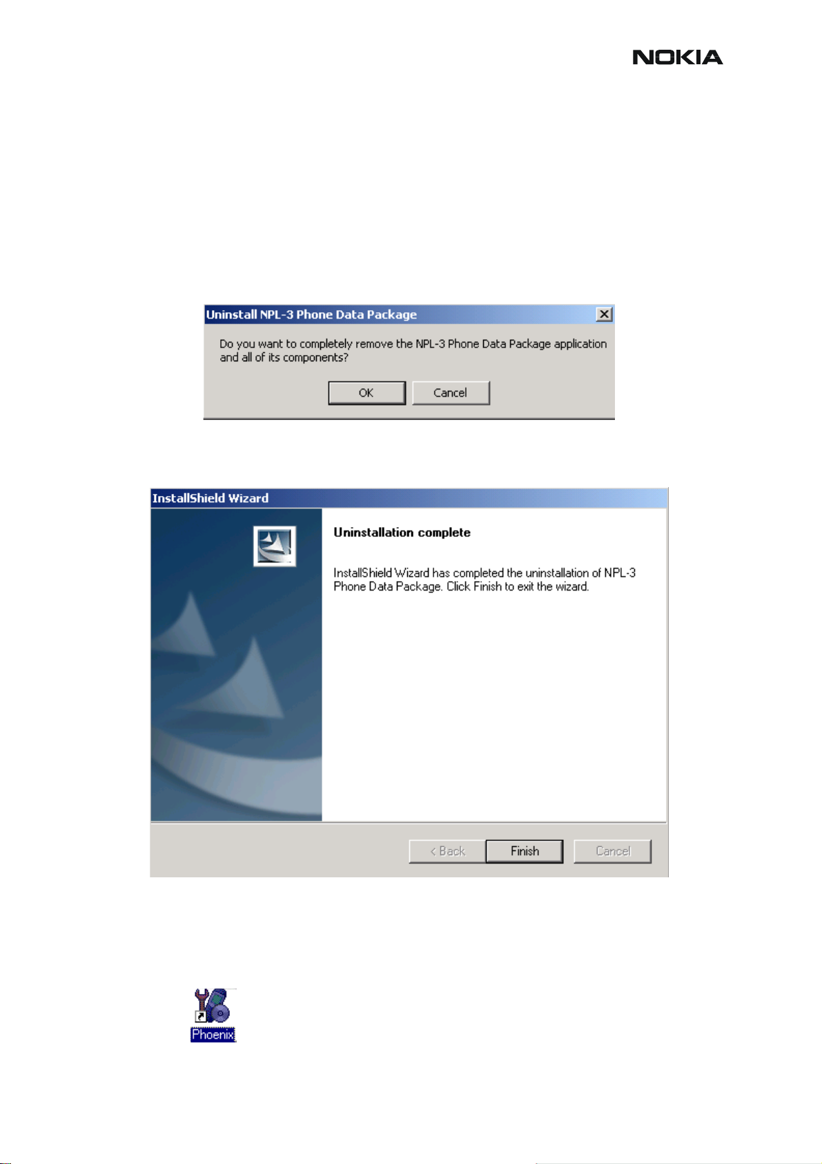
Uninstallation can also be done manually from Windows Control Panel / Add / Remove Programs/ “RM-12 Phone Data Package”.
If you try to install the same version of Phoenix Data Package that you already have, you are
asked if you want to uninstall the version you have on your PC. Answer “OK” to uninstall, “Cancel” if you don’t want to uninstall. Older versions of data packages do not need to be uninstalled.
Once the previously installed Data package is uninstalled, choose “Finish”.
Run the RM-12_dp_v1.0_sw3.02.exe again to continue installation from the beginning.
How to Manage Connections
Start Phoenix Service SW and Login.
Issue 1 11/2004 COMPANY CONFIDENTIAL 17
Copyright © 2004 Nokia. All Rights Reserved.
Page 20
RM-12
CCS Technical Documentation
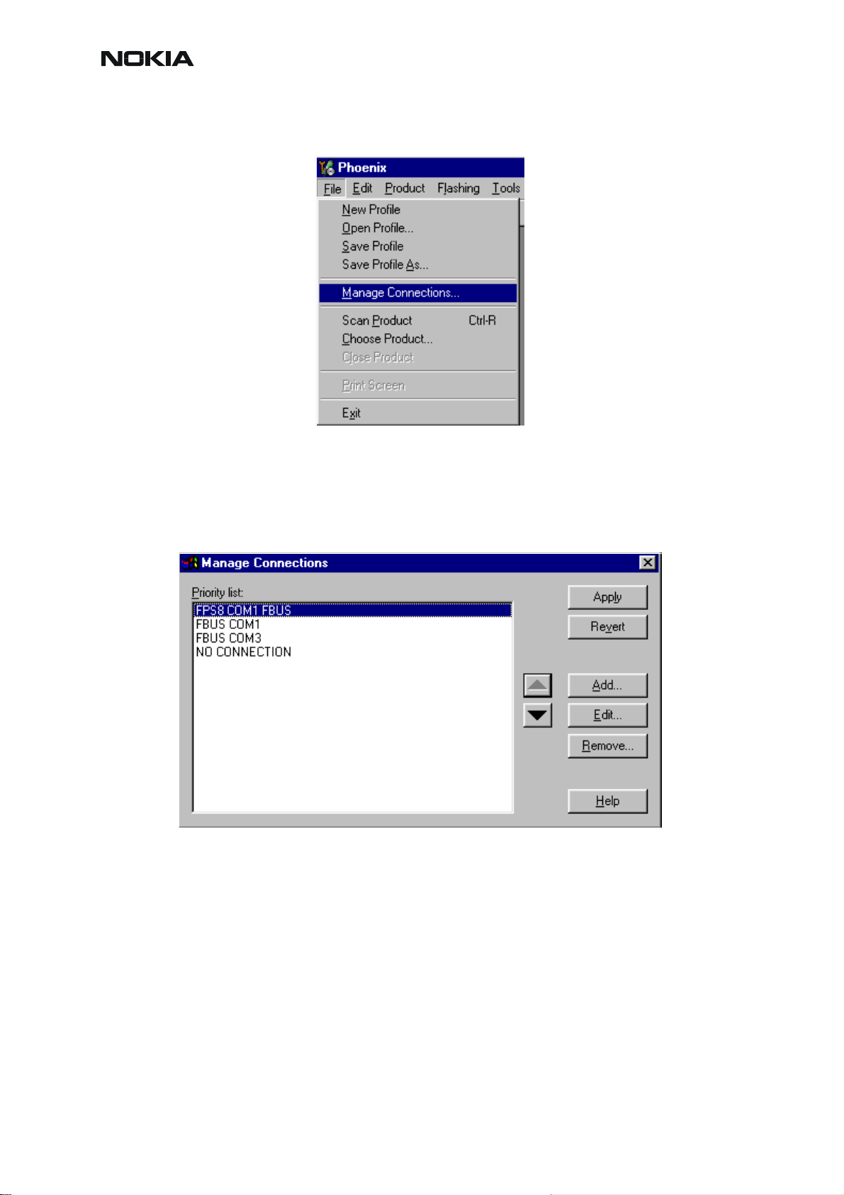
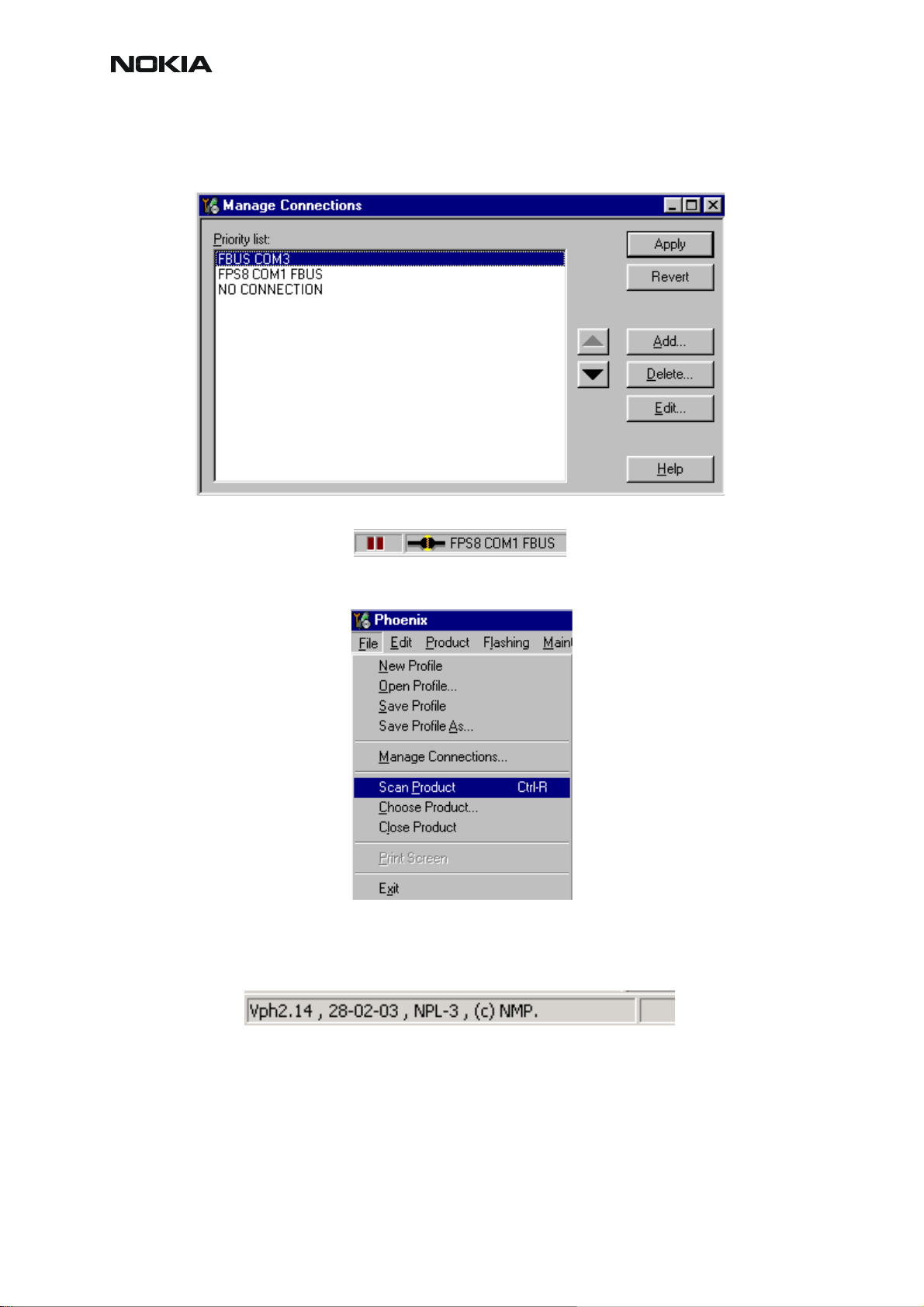
Choose “Manage Connections” From “File” – Menu
Existing connections can be selected, edited, deleted and new ones created by using this dialog.
A connection can be created either manually or by using a Connection Wizard.
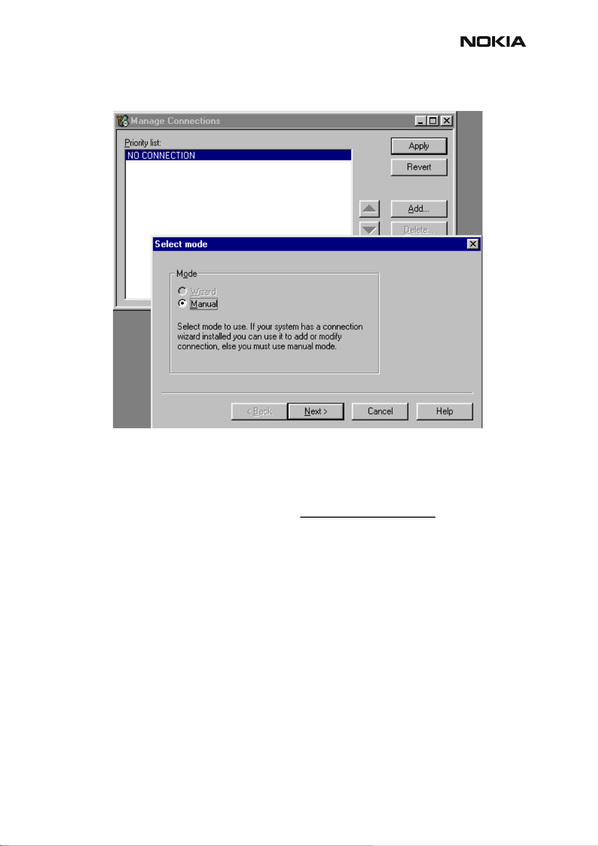
To add new connection, choose “Add” and select if you want to create it manually or by using
the Wizard.
Choose “Next” to continue.
18 COMPANY CONFIDENTIAL Issue 1 11/2004
Copyright © 2004 Nokia. All Rights Reserved.
Page 21
RM-12
CCS Technical Documentation
In the next dialogs you will be asked to select some settings for the connection
Manual Settings
A) For FLS-4S POS Flash Device choose following connection settings:
Media: FBUS
COM Port: Virtual COM Port used by FLS-4S. Please check this always!
(To check please go to Windows / Control Panel / FLS Virtual Port / Configuration)
B) For FPS-8 Flash Prommer choose following connection settings:
Media: FPS-8
Port Num: COM Port where FPS-8 is connected
COMBOX_DEF_MEDIA: FBUS
Choose “Finish” to complete.
If you use the Wizard, connect the tools and a phone to your PC and the wizard will automati-
cally try to configure the correct connection.
Activate the connection you want to use by clicking it and use up/down arrows to move it on
top of the list. Choose “Apply”.
Issue 1 11/2004 COMPANY CONFIDENTIAL 19
Copyright © 2004 Nokia. All Rights Reserved.
Page 22
RM-12
CCS Technical Documentation
The connection is now selected and can be used after closing the “Manage Connections” window.
Selected connection will be shown on the right hand bottom corner of the screen.
To use the selected connection, connect the phone to Phoenix with correct service tools, make
sure that it is switched on and select “Scan Product”.
When the Product is found, Phoenix will load product support and when everything is ready,
name of the loaded product support module and its version will be shown on the bottom of the
screen.
20 COMPANY CONFIDENTIAL Issue 1 11/2004
Copyright © 2004 Nokia. All Rights Reserved.
Page 23
RM-12
CCS Technical Documentation
How to Update Flash Support Files for FPS-8* and FLS-4S*
Before Installation
• Install Phoenix Service SW and Phoenix data package.
• Install the phone model Specific Datapackage for Phoenix
• The flash support files are delivered in the same installation package with
Phoenix data package.
• Normally it is enough to install the data package only before updating the FPS-
8.
• Separate installation package is for flash support files are available, and the
files can be updated according to this instruction.
Installing the Flash Support Files
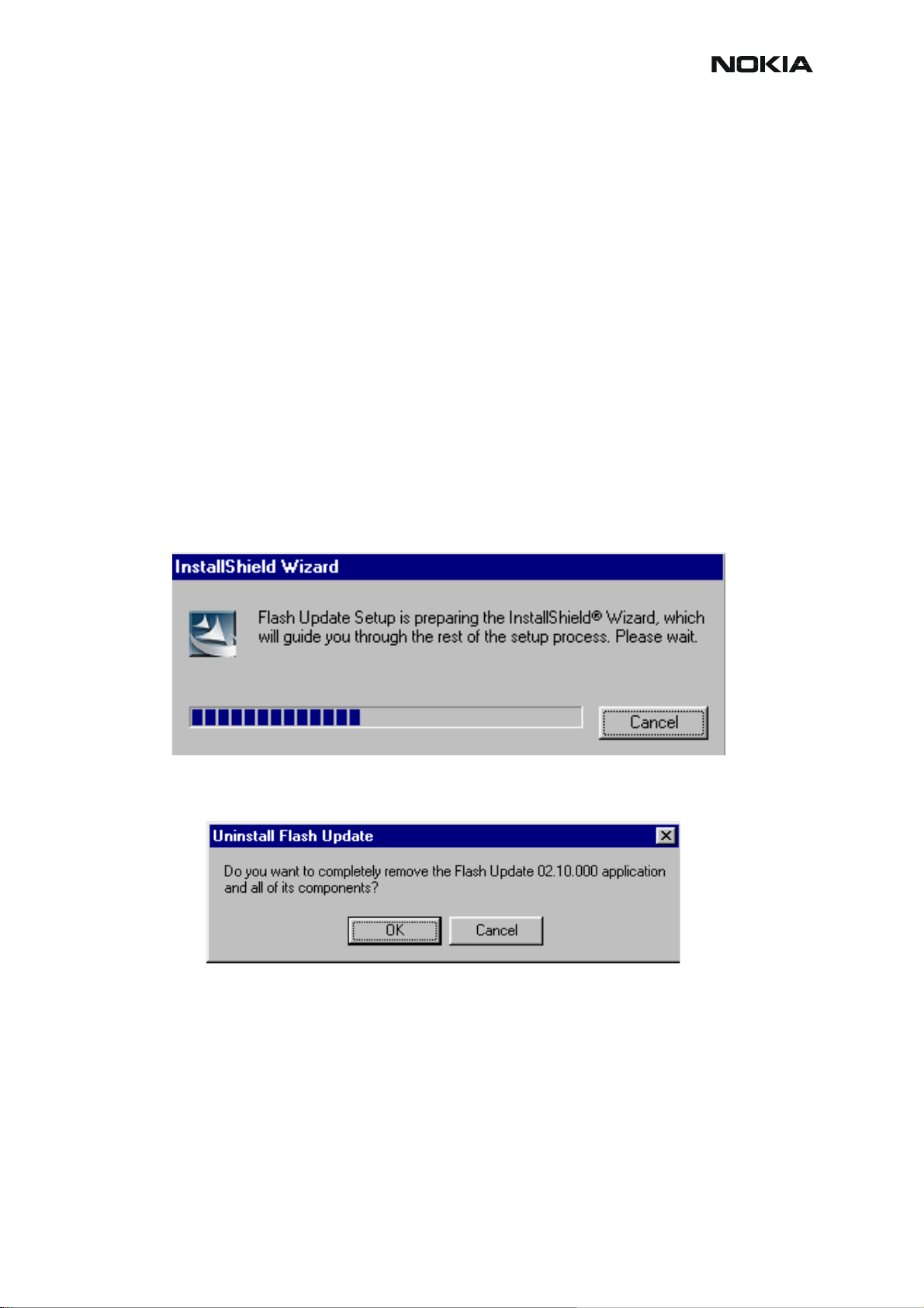
Start by double clicking eg. flash_update_02_10_00.exe. Installation begins.
If you already have the same Flash Update package files installed, you need to confirm if you
want them to be reinstalled.
Issue 1 11/2004 COMPANY CONFIDENTIAL 21
Copyright © 2004 Nokia. All Rights Reserved.
Page 24
CCS Technical Documentation
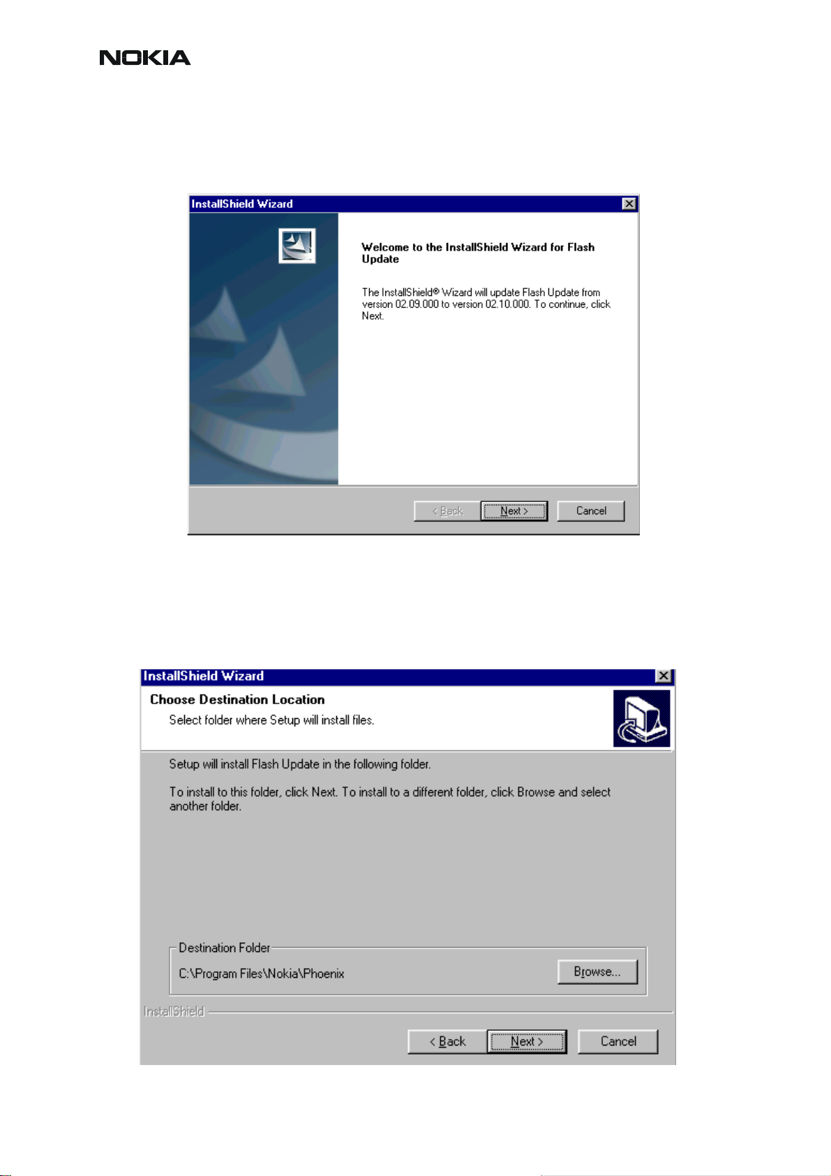
Choose “Next” to continue installation
RM-12
It is highly recommended to install the files to the default destination folder C:\Program
Files\Nokia\Phoenix.
Choose “Next” to continue. You may choose another location by selecting “Browse” (not recommended).
22 COMPANY CONFIDENTIAL Issue 1 11/2004
Copyright © 2004 Nokia. All Rights Reserved.
Page 25
RM-12
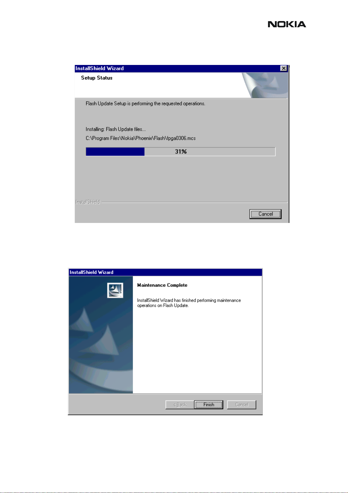
Installation continues…
CCS Technical Documentation
Choose “Finish” to complete procedure.
• FLS-4S can be used right after Flash Update Package is installed.
• FPS-8* must be updated by using Phoenix!
Issue 1 11/2004 COMPANY CONFIDENTIAL 23
Copyright © 2004 Nokia. All Rights Reserved.
Page 26
RM-12
CCS Technical Documentation
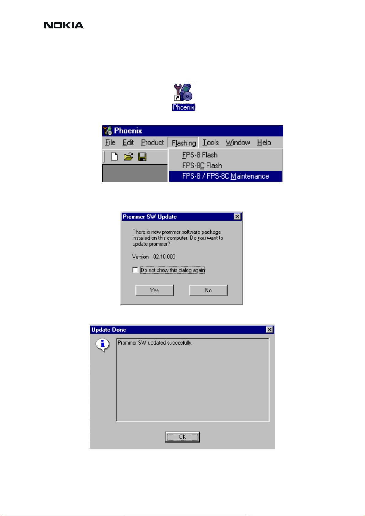
How to Update The FPS-8* Flash Prommer SW
Start Phoenix Service Software
Select”FPS-8 / FPS-8C maintenance” from”Flashing” menu.
When new FPS-8 flash update package is installed to computer you will be asked to update
the files to your FPS-8 Prommer. Select”Yes” to update files..
0200
Update procedure takes a couple of minutes.
24 COMPANY CONFIDENTIAL Issue 1 11/2004
Copyright © 2004 Nokia. All Rights Reserved.
Page 27
RM-12
CCS Technical Documentation
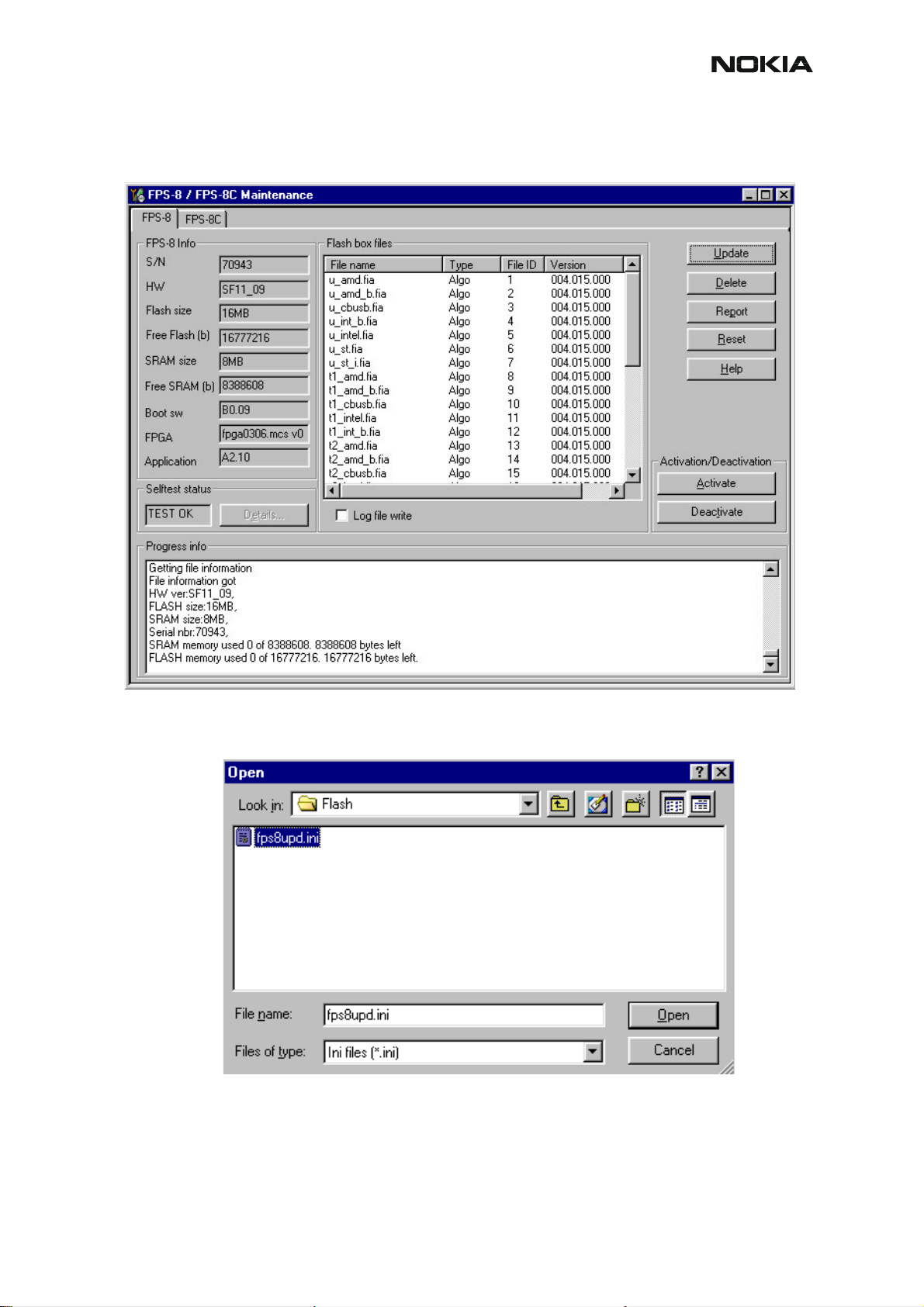
FPS-8 sw can also be updated by pressing”Update” button and selecting appropriate
fps8upd.ini file under C:\Program Files\Nokia\Phoenix\Flash - directory
All files can be loaded separately to FPS-8. To do this, just press right mouse button in Flash
box files” window and select file type to be loaded.
More information and help can be found from the “Help” dialog.
Issue 1 11/2004 COMPANY CONFIDENTIAL 25
Copyright © 2004 Nokia. All Rights Reserved.
Page 28

RM-12
CCS Technical Documentation
FPS-8 Activation and Deactivation
• Before the FPS-8 can be successfully used for phone programming, it must be
first activated.
• If there is a need to send FPS-8 box to somewhere e.g. for repair, box must be
first deactivated.
Activation
Before FPS-8 can be successfully used for phone programming, it must be first activated.
Fill in first “FPS-8 activation request” sheet, in the FPS-8 sales package and follow the in struc-
tions in the sheet.
When activation file is received (e.g. 00000.in), copy it to C:\ProgramFiles\Nokia\Phoe-
nix\BoxActivation - Directory on your computer (This directory is created when Phoenix is installed).
Start Phoenix Service Software.
Select ”FPS-8 / FPS-8C maintenance” from ”Flashing” menu.
Select “Activate” from the “FPS8/8C Maintenance” – UI.
26 COMPANY CONFIDENTIAL Issue 1 11/2004
Copyright © 2004 Nokia. All Rights Reserved.
Page 29

RM-12
CCS Technical Documentation
The activation file you saved to C:\ProgramFiles\Nokia\Phoenix\BoxActivation - directory will
be shown (e.g. 00000.in), check that it is correct.
Box will be activated when you choose “Open”.
Turn FPS-8 power off and on to complete activation.
Issue 1 11/2004 COMPANY CONFIDENTIAL 27
Copyright © 2004 Nokia. All Rights Reserved.
Page 30

CCS Technical Documentation
Deactivation
Start Phoenix Service Software.
Select ”FPS-8 / FPS-8C maintenance” from ”Flashing” menu.
Select “Deactivate” from the “FPS8/8C Maintenance” – UI.
Confirm Deactivation by choosing “Yes”, Box will be deactivated.
RM-12
Turn FPS-8 power off and on to complete deactivation.
28 COMPANY CONFIDENTIAL Issue 1 11/2004
Copyright © 2004 Nokia. All Rights Reserved.
Page 31

RM-12
CCS Technical Documentation
JBV-1 Docking Station SW
The JBV-1 Docking Station is a common tool for all DCT-4 generation products. In order to
make the JBV-1 usable with different phone models, a phone specific Docking Station Adapter
is used for different service functions.
The JBV-1 Docking Station contains Software (Firmware) which can be updated.
You need the following equipment to be able to update JBV-1 software:
• PC with USB connection
• Operating System supporting USB (Not Win 95 or NT)
• USB Cable (Can be purchased from shops or suppliers providing PC hardware and
accessories)
• JBV-1 Docking Station
• External Power Supply 11-16V
Before Installation
• Download Jbv1_update.zip – file to your computer (e.g. C:\TEMP) from your down-
load web site.
• Close all other programs
• Follow instructions on the screen
Issue 1 11/2004 COMPANY CONFIDENTIAL 29
Copyright © 2004 Nokia. All Rights Reserved.
Page 32

CCS Technical Documentation
Installing SW Needed for the JBV-1 SW Update
Note: DO NOT CONNECT THE USB CABLE / JBV-1 TO YOUR COMPUTER YET!
Run Jbv1_update.zip file and start SW Installation by double clicking Setup.exe.
Files needed for JBV-1 Package setup Program will be extracted.
RM-12
Installation begins, please read the information shown and Choose “Next” to continue.
30 COMPANY CONFIDENTIAL Issue 1 11/2004
Copyright © 2004 Nokia. All Rights Reserved.
Page 33

RM-12
CCS Technical Documentation
Use suggested destination folder where JBV-1 SW Package will be installed and choose “Next”
to continue.
Select “Full” Installation and choose “Next” to continue
Issue 1 11/2004 COMPANY CONFIDENTIAL 31
Copyright © 2004 Nokia. All Rights Reserved.
Page 34

RM-12
CCS Technical Documentation
Program Folder will be created. Choose “Next” to continue, Software files will be installed.
After successful installation, choose “Finish” to complete.
NOW YOU CAN CONNECT THE USB CABLE / JBV-1 TO YOUR COMPUTER!
32 COMPANY CONFIDENTIAL Issue 1 11/2004
Copyright © 2004 Nokia. All Rights Reserved.
Page 35

RM-12
CCS Technical Documentation
Connect power to JBV-1 (11-16V DC) from external power supply, then connect USB Cable
between JBV-1 USB connector and PC.
Windows will detect connected USB cable and detect drivers for new HW.
Follow the instructions and allow Windows to search and install the best drivers available. After
this procedure the actual JBV-1 SW update can begin.
Issue 1 11/2004 COMPANY CONFIDENTIAL 33
Copyright © 2004 Nokia. All Rights Reserved.
Page 36

RM-12
CCS Technical Documentation
Updating the JBV-1 Docking Station Software
Go to folder C:\Program Files\Nokia\ JBV-1 SW Package\ FIRMWARE UPDATE and start
JBV-1 Update SW by double clicking fwup.exe.
JBV-1 Firmware update starts and shows current status of the JBV-1 connected.
If firmware version read from your JBV-1 is not the latest one available, it needs to be updated
by choosing “Update Firmware”.
Choose file JBV1v11.CDE (example used here is for v 11) and “Open” to update your JBV-1.
After successful update, current JBV-1 status will be shown. You have now updated the software of your JBV-1 docking station and it is ready for use.
34 COMPANY CONFIDENTIAL Issue 1 11/2004
Copyright © 2004 Nokia. All Rights Reserved.
Page 37

RM-12
CCS Technical Documentation
Issue 1 11/2004 COMPANY CONFIDENTIAL 35
Copyright © 2004 Nokia. All Rights Reserved.
Page 38

CCS Technical Documentation
RM-12
[This page left blank intentionally]
36 COMPANY CONFIDENTIAL Issue 1 11/2004
Copyright © 2004 Nokia. All Rights Reserved.
Page 39

RM-12
CCS Technical Documentation
Receiver tuning: Quick Guide for Tuning With Phoenix
2004
General remarks
RF tunings must be performed in the same order as shown in this document. The order of the
corresponding menu items in the Service SW may be different.
If baseband tunings are needed, they should be completed before the RF tunings.
Avoid unnecessary tuning – factory-tuning values are always the most accurate ones.
NOTE! RF tunings need to be done ONLY if any RF block component is replaced.
Screen shots described in this document may change as the service software is developed.
Kindly refer to the Phoenix help files, the phone model specific service manual and bulletins for
help.
Issue 1 11/2004 COMPANY CONFIDENTIAL 37
Copyright © 2004 Nokia. All Rights Reserved.
Page 40

CCS Technical Documentation
Service Tool Concept for RF Tuning Operations
NOTE! RF tunings need to be done ONLY if any RF block component is replaced.
• Power to MJ-32 must be supplied from an external DC power supply, not FPS8 prommer
• MJ-32 input voltages: 4 - 12V DC.
Remember the cable attenuation when setting required RF levels
6
RM-12
5
2
3
Figure 1: RF tuning setup
Table 1:
1
Item: Service accessory: Type:
1 Module jig MJ-32
2 DC power cable PCS-1
3 Modular cable XRF-1
4 Service Mbus cable DAU-9S
4
5 Software protection key PKD-1
6 Service SW CD-ROM
38 COMPANY CONFIDENTIAL Issue 1 11/2004
Copyright © 2004 Nokia. All Rights Reserved.
Page 41

RM-12
CCS Technical Documentation
Autotuning
Autotune feature is designed to align product’s RF part easier and faster. By this autotune component the product is tuned automatically. The user only needs to press ‘Tune’ and the product’s RF is tuned and results are shown to the user. Component controls all the needed RF
equipment (RF generator and TX measuring device) except voltage supplier.
NOTE! Automatic tuning is ALWAYS the primary tuning mode. Manual tuning is not recommended.
Following diagram describes how the Autotune component is located in the TSS architecture:
Figure 2: Autotune component in TSS architecture
Autotune is a pair of two different components. One is User Interface and the other is Functional. UI does not contain any functionality. MTI takes care of phone messages.
The Autotune component can be found under Tuning menu:
Figure 3: Autotune menu in Phoenix
Issue 1 11/2004 COMPANY CONFIDENTIAL 39
Copyright © 2004 Nokia. All Rights Reserved.
Page 42

CCS Technical Documentation
Figure 4: Autotune menu - RX/TX menu
RM-12
Set Loss
Figure 5: Set Loss menu
This is the component for saving RF-losses (of cables and jigs) to file. These loss values are
needed when you tune the phone with Phoenix (using Autotuning component). When you
measure the losses you have to be very careful, because these value s affect directly how well
the phone is tuned.
NOTE! This component is only for Autotuning use.
40 COMPANY CONFIDENTIAL Issue 1 11/2004
Copyright © 2004 Nokia. All Rights Reserved.
Page 43

RM-12
CCS Technical Documentation
Figure 6: Loss values
Environment
Hardware requirements:
PC with Windows 2000/XP
Power supply
Product-specific module jig
RF-splitter and -cables
RF equipment (only one of each is needed)
TX:
Agilent E4406 (VSA series transmitter tester)
Agilent E4445 (PSA series transmitter tester)
Rohde&Schwarz, FSE-family of Signal Analyzers
Rohde&Schwarz, FSIQ-family of Signal Analyzers
RX:
Agilent ESG family of RF Signal Generators
Rohde&Schwarz, SME-family of Signal Generators
Issue 1 11/2004 COMPANY CONFIDENTIAL 41
Copyright © 2004 Nokia. All Rights Reserved.
Page 44

CCS Technical Documentation
Figure 7: Preferred setup environment
Figure 8: Alternative setup environment
RM-12
GPIB addresses are not defined. Component finds the addresses and uses them automatically.
If several TX tuning devices are connected, this component uses Agilent (VSA or PSA). In RX
side, Agilent has highest priority.
Protection
Components are protected by PKD-1CS, PKD-1NS, PKD-1 and PKD-1P dongles using standard TSS protection procedure. Autotuning itself is possible with all these dongles b ut with PKD1P and PKD-1 dongles user is not able to set the loss.
Receiver Manual Tuning
RX Channel Select Filter Calibration
Extra equipment / external RF signal not allowed.
Must be done before other RX calibrations.
This function is used to calibrate RX channel select filter in GSM Phones.
Rx Channel select filter is tuned only in one band = Single calibration for both bands.
42 COMPANY CONFIDENTIAL Issue 1 11/2004
Copyright © 2004 Nokia. All Rights Reserved.
Page 45

RM-12
CCS Technical Documentation
Select Tuning => Rx Channel select filter calibration.
“Save to Phone “ is checked by default
Uncheck “Save to Phone “ if you don´t want the values to be saved to phone (eg testing)!
Press "Tune" to start the tuning
Tuning values must be 0…31
If values shown are within limits, choose “Stop”
Close the “RX Channel Select Filter Calibration“-dialog to end tuning
Close the Rx Channel select filter calibration dialog, the values are saved to phone
Issue 1 11/2004 COMPANY CONFIDENTIAL 43
Copyright © 2004 Nokia. All Rights Reserved.
Page 46

CCS Technical Documentation
RX Calibration
RF generator needed.
This tuning performs RX Calibration.
RM-12
Must be done separately on every band
Calibration is automatically performed at GSM900, then at GSM1800 and finally at GSM1900
band. If tuning is successful, it continues in the next band.
AFC tuning is done while GSM900 band RX Calibration is performed.
Remember to take jig and cable attenuations into account!
Select Tuning => Rx calibration
Press “Start"´to start tuning.
!
Set RF generator to required GSM900 frequency => OK
44 COMPANY CONFIDENTIAL Issue 1 11/2004
Copyright © 2004 Nokia. All Rights Reserved.
Page 47

RM-12
Set RF generator to required frequency => OK
Tuning values and ADC readings are shown.
Typical values and limits in GSM900 RX Calibration:
Table 2:
CCS Technical Documentation
GSM900 Typical value Low limit High limit
Afc value: 130 -350 350
Afc slope: 140 90 165
900
typ min max
rssi 0 65 55 75
rssi 1 71 61 81
rssi 2 77 67 87
rssi 3 83 73 93
rssi 4 89 79 99
rssi 5 94 84 104
rssi 6 100 90 110
rssi 7 106 96 116
rssi 8 112 102 122
rssi 9 118 108 128
rssi 10 124 114 134
rssi 11 130 120 140
rssi 12 136 126 146
rssi 13 142 132 152
rssi 14 148 138 158
Press “Save and continue”, then starts GSM1800 calibration.
Set RFgenerator to required GSM1800 frequency => OK
Issue 1 11/2004 COMPANY CONFIDENTIAL 45
Copyright © 2004 Nokia. All Rights Reserved.
Page 48

CCS Technical Documentation
Tuning values and ADC readings are shown.
Typical values and limits in (GSM1800) RX Calibration
1800
typ min max
rssi 0 63 53 73
rssi 1 69 59 79
rssi 2 75 65 85
rssi 3 81 71 91
rssi 4 87 77 97
rssi 5 92 82 102
rssi 6 98 88 108
rssi 7 104 94 114
rssi 8 110 100 120
rssi 9 116 106 126
rssi 10 122 112 132
rssi 11 128 118 138
rssi 12 134 124 144
rssi 13 140 130 150
rssi 14 146 136 156
RM-12
Press “Save and continue”, then starts GSM1900 calibration.
Set the RF generator to required GSM1900 frequency => OK
Tuning values and ADC readings are shown.
46 COMPANY CONFIDENTIAL Issue 1 11/2004
Copyright © 2004 Nokia. All Rights Reserved.
Page 49

RM-12
Typical values and limits in (GSM1900) RX Calibration
1900
typ min max
rssi 0 66 56 76
rssi 1 72 62 82
rssi 2 78 68 88
rssi 3 84 74 94
rssi 4 90 80 100
rssi 5 94 84 104
rssi 6 99 89 109
rssi 7 105 95 115
rssi 8 111 101 121
rssi 9 117 107 127
rssi 10 123 113 133
rssi 11 129 119 139
rssi 12 135 125 145
rssi 13 141 131 151
rssi 14 147 137 157
CCS Technical Documentation
Press “Save and continue”.
If values are within limits, they are saved to the phone after successful tuning of each band.
Close the “Rx Calibration” dialog to end tuning
Issue 1 11/2004 COMPANY CONFIDENTIAL 47
Copyright © 2004 Nokia. All Rights Reserved.
Page 50

CCS Technical Documentation
RX Band Filter Response Compensation
RF generator needed.
RM-12
This operation must be done separately on each band
Start RX Calibration at GSM900, then continue at GSM1800 band and finally on the GSM1900
band
NOTE! Remember to do RX calibration before doing Rx Band Filter Response Compensation!
Remember to take jig and cable attenuations into account!
Select Tuning => Rx band filter response compensation
Press “Start” to start tuning with values already saved to the phone
!
Select "Manual tuning" and tuning starts.
48 COMPANY CONFIDENTIAL Issue 1 11/2004
Copyright © 2004 Nokia. All Rights Reserved.
Page 51

RM-12
CCS Technical Documentation
You are asked to supply 9 different RF frequencies to the phone.
The tuning begins from GSM900 band and continues the same way for GSM 1800 and
GSM1900 bands
Set the first required frequency and level => OK
Set the 2nd required frequency and level => OK
Set the 3rd required frequency and level => OK
Issue 1 11/2004 COMPANY CONFIDENTIAL 49
Copyright © 2004 Nokia. All Rights Reserved.
Page 52

CCS Technical Documentation
Set the 4th required frequency and level => OK
Set the 5th required frequency and level => OK
RM-12
Set the 6th required frequency and level => OK
50 COMPANY CONFIDENTIAL Issue 1 11/2004
Copyright © 2004 Nokia. All Rights Reserved.
Page 53

RM-12
Set the 7th required frequency and level => OK
Set the the 8th required frequency and level => OK
CCS Technical Documentation
Set 9th required frequency and level => OK
Issue 1 11/2004 COMPANY CONFIDENTIAL 51
Copyright © 2004 Nokia. All Rights Reserved.
Page 54

CCS Technical Documentation
RM-12
Limits in Rx Band Filter Response Compensation GSM900:
Input
Channel
Frequency (MHz)
965 923.26771 -10 3.5
975 925.26771 -3.5 3.5
987 927.66771 -3.5 3.5
1009 932.06771 -3.5 3.5
37 924.46771 -3.5 3.5
90 953.06771 -3.5 3.5
114 957.86771 -3.5 3.5
124 959.86771 -3.5 3.5
136 962.26771 -10 3.5
Low limit (dB) High limit (dB)
If the values shown are within limits, press “Save and continue” to save values to the phone,
then the GSM1800 tuning starts automatically.
Repeat the same steps as for the GSM900 band above.
52 COMPANY CONFIDENTIAL Issue 1 11/2004
Copyright © 2004 Nokia. All Rights Reserved.
Page 55

RM-12
CCS Technical Documentation
Limits in Rx Band Filter Response Compensation GSM1800:
Input
Channel
Frequency (MHz)
497 1802.26771 -10 3.5
512 1805.26771 -3.5 3.5
535 1809.86771 -3.5 3.5
606 1824.06771 -3.5 3.5
700 1842.86771 -3.5 3.5
791 1861.06771 -3.5 3.5
870 1876.86771 -3.5 3.5
885 1879.86771 -3.5 3.5
908 1884.46771 -10 3.5
If the values shown are within limits, press “Save and continue” to save values to the phone,
then the GSM1900 tuning starts automatically.
Repeat the same steps as for the GSM900 and GSM1800 bands above.
Low limit (dB) High limit (dB)
Limits in Rx Band Filter Response Compensation GSM1900:
Input
Channel
Frequency (MHz)
Low limit (dB) High limit (dB)
496 1927.06771 -10 3.5
512 1930.26771 -3.5 3.5
537 1935.26771 -3.5 3.5
586 1945.06771 -3.5 3.5
661 1960.06771 -3.5 3.5
736 1975.06771 -3.5 3.5
794 1986.66771 -3.5 3.5
810 1989.86771 -3.5 3.5
835 1994.86771 -10 3.5
If the values shown are within limits, press “Save and continue” to save values to the phone.
Close the “RX Band Filter Response Compensation” – dialog to end tuning.
Issue 1 11/2004 COMPANY CONFIDENTIAL 53
Copyright © 2004 Nokia. All Rights Reserved.
Page 56

CCS Technical Documentation
Rx Am Suppression
RF generator is needed.
RM-12
Must be done separately on each band
Start RX Am Suppression at GSM900, then continue at GSM1800 band and finally at the
GSM1900 band.
Remember to take jig and cable attenuations into account!
Select Tuning => Rx Am Suppression
Press “Start” to begin tuning.
!
54 COMPANY CONFIDENTIAL Issue 1 11/2004
Copyright © 2004 Nokia. All Rights Reserved.
Page 57

RM-12
Adjust signal generator accordingly and press “OK” to tune.
CCS Technical Documentation
When tuning is finished, press “Save & Continue”.
Tuning continues automatically at GSM1800 band.
Adjust signal generator accordingly and press “OK” to tune.
Issue 1 11/2004 COMPANY CONFIDENTIAL 55
Copyright © 2004 Nokia. All Rights Reserved.
Page 58

CCS Technical Documentation
When tuning is finished, press “Save & Continue”.
Tuning continues automatically at GSM1900 band.
Adjust signal generator accordingly and press “OK” to tune.
RM-12
When tuning is finished, press “Save & Continue”.
56 COMPANY CONFIDENTIAL Issue 1 11/2004
Copyright © 2004 Nokia. All Rights Reserved.
Page 59

RM-12
CCS Technical Documentation
If the Rx Am Suppression tuning was completed successfully, press “OK” to stop tuning.
Close the Rx Am Suppression window.
Issue 1 11/2004 COMPANY CONFIDENTIAL 57
Copyright © 2004 Nokia. All Rights Reserved.
Page 60

CCS Technical Documentation
RX DTOS balance calibration
Extra equipment / external RF signal not allowed.
RM-12
Must be done separately on each band
Start RX Calibration for GSM900, then continue at the GSM1800 band and finally at the
GSM1900 band.
This Calibration is used for calibrating DSP control words values.
Select Tuning => Rx DtoS Balance Calibration
NOTE! No RF-input is allowed to feed when calibrating
Choose “OK” and “Start”, tuning begins automatically at the GSM900 band.
!
58 COMPANY CONFIDENTIAL Issue 1 11/2004
Copyright © 2004 Nokia. All Rights Reserved.
Page 61

RM-12
CCS Technical Documentation
Press “Start” to start tuning.
Select “OK” to start tuning with values already saved to the phone
If values shown are within limits, press “Save and continue” to save values to the phone
GSM1800 and GSM1900 are calibrated automatically. If values are within limits, press “Save
and continue” to save values to the phone.
Close the RX DtoS Balance Calibration dialog to end Receiver tuning.
Issue 1 11/2004 COMPANY CONFIDENTIAL 59
Copyright © 2004 Nokia. All Rights Reserved.
Page 62

[This page intentionally blank]
Page 63

RM-12
CCS Technical Documentation
Transmitter Manual Tuning
TX Power Level Tuning
Power meter or spectrum analyzer needed.
With Tx Power Level Tuning, the coefficients are adjusted for each power level.
Start Power Level tuning at GSM900/EDGE, then continue at GSM1800/EDGE band and final-
ly at the GSM1900/EDGE band.
Tuning => Tx power level tuning
Select “Start”, tuning begins at the GSM900 band
Set up spectrum analyzer accordingly.
Issue 1 11/2004 COMPANY CONFIDENTIAL 61
Copyright © 2004 Nokia. All Rights Reserved.
Page 64

CCS Technical Documentation
Remember to take the jig and cable attenuations into account!
RM-12
The coefficient table lists the power level, coefficient and target dBm for each power level.
The tuned power level can be chosen by using up and down arrows or mouse.
The current power level is shown with inverse colors.
The tuning value can be adjusted with “-“ and “+” keys.
Use only High-mode (TxPA mode).
62 COMPANY CONFIDENTIAL Issue 1 11/2004
Copyright © 2004 Nokia. All Rights Reserved.
Page 65

RM-12
CCS Technical Documentation
Tune Base level and power levels 19, 15 and 5 to target level.
Press “Save and continue”.
Typical values: GSM900
Table 3:
Power level Coefficient
5 0.670…0.850
15 0.210…0.240
19 0.170…0.200
Base 0.140…0.170
Press “Save & Continue”. Tuning values will be calculated and saved to phone’s memory.
Issue 1 11/2004 COMPANY CONFIDENTIAL 63
Copyright © 2004 Nokia. All Rights Reserved.
Page 66

CCS Technical Documentation
Tuning at EDGE900
Set up spectrum analyzer accordingly.
RM-12
Press “OK” and start tuning.
Tune all power levels to target level. Use only High-mode (TxPA mode).
NOTE! Target for EDGE Base level is -15dBm.
64 COMPANY CONFIDENTIAL Issue 1 11/2004
Copyright © 2004 Nokia. All Rights Reserved.
Page 67

RM-12
CCS Technical Documentation
Press “Save & Continue” to save the tuning values to phone’s memory.
Tuning at GSM1800 band
Set up spectrum analyzer accordingly.
Remember to take the jig and cable attenuations into account!
Press “OK” and start tuning.
Issue 1 11/2004 COMPANY CONFIDENTIAL 65
Copyright © 2004 Nokia. All Rights Reserved.
Page 68

RM-12
CCS Technical Documentation
Tune Base level and power levels 15,11 and 0 to target level.
Typical values: GSM1800
Table 4:
Power level Coefficient
0 0.580…0.700
11 0.210...0.240
15 0.180…0.210
Base 0.135…0.165
Press “Save & Continue”. Tuning values will be calculated and saved to phone’s memory.
Tuning at EDGE1800
Set up spectrum analyzer accordingly.
66 COMPANY CONFIDENTIAL Issue 1 11/2004
Copyright © 2004 Nokia. All Rights Reserved.
Page 69

RM-12
Press “OK” and start tuning.
CCS Technical Documentation
Tune all power levels to target level.
NOTE! Target for EDGE Base level is -15dBm.
Press “Save & Continue” to save the tuning values to phone’s memory.
Tuning at GSM1900 band
Set up spectrum analyzer accordingly.
Issue 1 11/2004 COMPANY CONFIDENTIAL 67
Copyright © 2004 Nokia. All Rights Reserved.
Page 70

CCS Technical Documentation
Remember to take the jig and cable attenuations into account!
Press “OK” and start tuning.
RM-12
Tune Base level
68 COMPANY CONFIDENTIAL Issue 1 11/2004
and power levels 15, 11 and 0 to target level.
Copyright © 2004 Nokia. All Rights Reserved.
Page 71

RM-12
Typical values: GSM1900
CCS Technical Documentation
Table 5:
Power
level
Coefficient
0 0.580…0.700
11 0.210…0.240
15 0.180…0.210
Base 0.150…0.165
Press “Save & Continue”. Tuning values will be calculated and saved to phone’s memory
Tuning at EDGE1900
Set up spectrum analyzer accordingly.
Issue 1 11/2004 COMPANY CONFIDENTIAL 69
Copyright © 2004 Nokia. All Rights Reserved.
Page 72

CCS Technical Documentation
Press “OK” and start tuning.
RM-12
Tune all power levels to target level.
NOTE! Target for EDGE Base level is -15dBm.
Press “Save & Continue” to save the tuning values to phone’s memory.
TX Power Level Tuning is now completed.
70 COMPANY CONFIDENTIAL Issue 1 11/2004
Copyright © 2004 Nokia. All Rights Reserved.
Page 73

RM-12
CCS Technical Documentation
TX I/Q Tuning
Spectrum analyzer needed.
Tx IQ Tuning allows changing the Tx I DC Offset, Tx Q DC Offset, Amplitude difference and
Phase difference.
Must be done separately on all bands
Select Tuning => Tx_IQTuning
Tx IQ Tuning window will open.
!
Press “Start” and tuning will begin at GSM900 band.
Issue 1 11/2004 COMPANY CONFIDENTIAL 71
Copyright © 2004 Nokia. All Rights Reserved.
Page 74

CCS Technical Documentation
Adjust spectrum analyzer accordingly.
RM-12
Press “OK” and start tuning.
Tuning is done by setting each of the sliders to desired value.
The order of tuning should be the same as the order of the sliders, that is, the Tx I DC Offset
is tuned first and Phase difference is tuned last.
Use <= , =>, PgUp or PgDn keys.
72 COMPANY CONFIDENTIAL Issue 1 11/2004
Copyright © 2004 Nokia. All Rights Reserved.
Page 75

RM-12
m
CCS Technical Documentation
Tune LO leakage to minimum with TXI/TXQ DC Offset control (f0 on spectrum analyzer
screen).
Tune unwanted sideband to minimum using Amplitude/Phase difference controls (f0 +
67.71kHz on spectrum analyzer screen).
RF Att 40 dB
Unit dB
A
Ref Lvl
Ref Lvl
33 dBm
33 dBm
33
21 dB Offset
30
20
10
Marker 1 [T1]
22.61 dBm
897.33246493 MHz
1
RBW 3 kHz
VBW 3 kHz
SWT 3 s
1 [T1] 22.61 dBm
897.33246493 MHz
1 [T1] -26.10 dB
67.77000000 kHz
2 [T1] -49.93 dB
135.87174348 kHz
0
-10
-20
-30
-40
-50
-60
-67
Center 897.4 MHz Span 200 kHz20 kHz/
Date: 3.JUN.2003 12:32:03
1
2
1MA
Tuning limits are the same for all bands (GSM/EDGE900, GSM/EDGE1800 and GSM/
EDGE1900):
Table 6:
Tuning limits:
I DC Offset -6…+6
Q DC Offset -6…+6
Amplitude difference -1…+1
Phase difference - 80°…100°
When the IQ spectrum is balanced, “Save & Continue” to EDGE900 TX IQ tuning.
Spectrum analyzer settings are the same as for GSM900 IQ tuning.
Issue 1 11/2004 COMPANY CONFIDENTIAL 73
Copyright © 2004 Nokia. All Rights Reserved.
Page 76

CCS Technical Documentation
m
A
7
NOTE! In EDGE-mode, the unwanted sideband is located at 50.8kHz from f0.
Delta 1 [T1]
Ref Lvl
Ref Lvl
33 dBm
33 dBm
33
21 dB Offset
30
20
10
-11.48 dB
50.93633267 kHz
1
RBW 3 kHz
VBW 3 kHz
SWT 3 s
1
RF Att 40 dB
Unit dB
1 [T1] 23.28 dBm
897.34929860 MHz
1 [T1] -11.48 dB
50.93633267 kHz
2 [T1] -26.84 dB
102.20440882 kHz
RM-12
A
0
-10
-20
-30
-40
-50
-60
-6
Center 897.4 MHz Span 200 kHz20 kHz/
Date: 3.JUN.2003 12:37:09
When the IQ spectrum is balanced, press “Save & Continue”.
Tuning at GSM/EDGE1800 band
Adjust spectrum analyzer accordingly.
2
1M
Both GSM and EDGE 1800 use the same settings.
74 COMPANY CONFIDENTIAL Issue 1 11/2004
Copyright © 2004 Nokia. All Rights Reserved.
Page 77

RM-12
Tuning at GSM/EDGE1900 band
Adjust spectrum analyzer accordingly.
CCS Technical Documentation
Both GSM and EDGE 1900 use the same settings.
When GSM and EDGE 1900 are tuned, press “Save & Continue”.
Press “OK” and the TX IQ Tuning is completed.
Issue 1 11/2004 COMPANY CONFIDENTIAL 75
Copyright © 2004 Nokia. All Rights Reserved.
Page 78

RM-12
CCS Technical Documentation
Service Tool Concept For Baseband Tuning Operations
EM calibrations should be carried out in JBV-1 Docking Station equipped with DA-43 Docking
Station Adapter.
NOTE! RF tunings can be carried out in MJ-32 module jig and JBV-1, DA-43 and SA-63.
Power to JBV-1 should be supplied from an external DC power supply, not FPS-8 prommer.
JBV-1 input voltages:
Maximum +16 VDC
Nominal input for RF tunings is +12 V DC.
76 COMPANY CONFIDENTIAL Issue 1 11/2004
Copyright © 2004 Nokia. All Rights Reserved.
Page 79

RM-12
Service Concept for RM-12* Baseband tunings
8
CCS Technical Documentation
7
6
5
3
Item
1
Accessory
type
4
2
Table 7:
Service Accessory
1 JBV-1 Docking Station
2 DA-43 Docking Station adapter
3 CA-5S DC-DC Cable
5 PCS-1 DC power cable
6 DAU-9S Service FBUS cable
7 PKD-1 Software protection key
8 Service SW CD-ROM
Issue 1 11/2004 COMPANY CONFIDENTIAL 77
Copyright © 2004 Nokia. All Rights Reserved.
Page 80

RM-12
CCS Technical Documentation
Baseband Tuning operations
Energy Management Tuning
External power supply needed.
Energy Management (EM) Calibration is used for calibrating Battery and Charger settings of
the phone.
Preparation for EM Calibration:
- Connect the DC Cable CA-5S between JBV-1 and Vin of the Phone for Charger calibration.
- Connect 12…15 V from the Power Supply to JBV-1.
- NOTE! Check that the connection is F-BUS (does not work with M-BUS).
Select Tuning => Energy Management Calibration.
Energy Management values to be calibrated are checked.
Select “Read from Phone” to show the current values in the phone memory and to check that
the communication with the phone works.
78 COMPANY CONFIDENTIAL Issue 1 11/2004
Copyright © 2004 Nokia. All Rights Reserved.
Page 81

RM-12
Select “Calibrate” to run the selected calibrations.
CCS Technical Documentation
Issue 1 11/2004 COMPANY CONFIDENTIAL 79
Copyright © 2004 Nokia. All Rights Reserved.
Page 82

CCS Technical Documentation
Limits for Energy Management Calibration:
Table 8:
Parameter Min. Max Note
ADC gain min 25400 29000 VBatt, BSI, BTemp
ADC offset -50 50 ADC voltage offset
BSI gain 970 1100 ADC BSI calibration gain
BTEMP gain 2075 2275 ADC BTEMP calibration gain
Vbatt gain 10000 11000 ADC VBATT Voltage gain
Vbatt offset 2300 2900 ADC VBATT Voltage offset scale
VChar gain 55000 65000 Charge voltage
IChar gain 3800 6000 Charge current
RM-12
IChar offset -500 500
BSI gain 970 1100
Battery Current gain 475mA 525mA
If values shown are within limits select “Save To Phone” to save the values in the phone.
NOTE! Only the values of the checked tunings (Battery size, Battery Temperature etc…) are saved.
Close the “Energy Management Calibration” – dialog to end tuning.
You must manually switch the phone on after exiting “Energy Management Calibration” – dia-
log.
80 COMPANY CONFIDENTIAL Issue 1 11/2004
Copyright © 2004 Nokia. All Rights Reserved.
Page 83

RM-12
Flashing Setup Instructions
POS (Point of Sale) Flash Concept
CCS Technical Documentation
Figure 8: POS flash
Table 9:
Item Type Description
1 FLA-46 Point Of sales flash loading adapter
2 XCS-1 Service cable
3 ACF-8 AC Charger
4 FLS-4S FLS-4S sales package E&A
FLS-4S, FLS-4S sales package APAC
FLS-4S, FLS-4S sales package US
5 Service SW CD-ROM
N/A Standard USB A-B cable
CA-28DS Cable for FLS-4S
NOTE! Instead of the standard USB A-B cable and XCS-1 concept, the CA-28DS concept can only be
used when FLS-4S is connected to the USB port of the PC.
Issue 1 11/2004 COMPANY CONFIDENTIAL 81
Copyright © 2004 Nokia. All Rights Reserved.
Page 84

CCS Technical Documentation
Flash Concept with Flashing adapter
RM-12
Figure 9: Flash comcept with flashing adapter
Table 10:
Item Type Description
1 FLA-46 Point of sales flash loading adapter
2 FLC-2 Power cable, incl. in FLA-46 sales package
3 XCS-4 Modular cable
4 FPS-8 Flash prommer box with 2x SF12 SRAM
5 Centronics (printer) cable, incl in FPS-8 sales
package
6 AXS-4 RS-232 (D9-D9) cable, incl in FPS-8 sales pack-
age
7 PKD-1 Software protection key
8 Service SW CD-ROM
9 ACF-8 AC charger, incl. in FPS-8 sales package
N/A Standard USB A-B cable
82 COMPANY CONFIDENTIAL Issue 1 11/2004
Copyright © 2004 Nokia. All Rights Reserved.
Page 85

RM-12
Module Jig Concept
CCS Technical Documentation
5
6
2
3
Figure 10: Module jig concept
1
Table 11:
Item Type Description
1 MJ-32 Module jig
2 PCS-1 DC power cable
4
3 XRF-1 RF antenna cable
4 DAU-9S Service FBUS cable
5 PKD-1 Software protection key
6 Service SW CD-ROM
Issue 1 11/2004 COMPANY CONFIDENTIAL 83
Copyright © 2004 Nokia. All Rights Reserved.
Page 86

CCS Technical Documentation
JBV-1 Flash Concept
RM-12
Figure 11: JBV-1 Flash concept
Table 12:
Item Type Description
1 JBV-1 Docking station
2 PCS-1 DC power cable
3 XCS-4 Modular cable
4 FPS-8 Flash prommer box
5 Printer cable Incl. in FPS-8 sales pack
6 AXS-4 D9 – D9 cable, incl. in FPS-8 sales pack
7 PKD-1 Software protection key
8 Service SW CD-ROM
9 ACF-8 AC Charger, incl. in FPS-8 sales pack
N/A Standard USB A-B cable
84 COMPANY CONFIDENTIAL Issue 1 11/2004
Copyright © 2004 Nokia. All Rights Reserved.
Page 87

RM-12
Service Concept
CCS Technical Documentation
7
8
4
3
2
1
Figure 12: Service Concept
Table 13:
6
5
Item Type Description
1 JBV-1 Docking station
2 DA-43 Docking station adapter
3 CA-5S DC-DC cable
4 XRF-1 RF antenna cable
5 PCS-1 DC power cable
6 DAU-9S Service FBUS cable
7 PKD-1 Software protection key
8 Service SW CD-ROM
SA-63 RF adapter
Note! This Service Concept is for BB and RF tuning and testing.
Issue 1 11/2004 COMPANY CONFIDENTIAL 85
Copyright © 2004 Nokia. All Rights Reserved.
 Loading...