

Page 1

NHL-2NA Series Transceivers
Disassembly Instructions
Issue 2 11/02 ¤Nokia Corporation
Page 2

Disassembly Instructions CCS Technical Documentation
[This page left intentionally blank]
Page 2 ¤Nokia Corporation Issue 2 11/02
Page 3

CCS Technical Documentation
Disassembly jig opened ...............................................................................................5
Phone with grip opened onto disassembly jig .............................................................6
Push transceiver module to separate module from grip ...............................................7
Protective tape disassembly from grip .........................................................................7
Flex connector disassembly from grip .........................................................................8
Detaching A-cover from transceiver .........................................................................12
Transceiver keymat from transceiver ........................................................................14
UI-module B&B connector ........................................................................................15
UI-module from chassis assembly .............................................................................16
SIM connector from acoustic chamber ......................................................................17
Camera module from acoustic chamber ....................................................................18
Dismantling main PWB from chassis assembly ........................................................20
Main PWB from chassis assembly ............................................................................21
Proximity sensor from chassis assembly: ..................................................................22
Proximity sensor from chassis assembly: ..................................................................23
Power key from chassis assembly: ............................................................................24
Dismantling keymat cover assembly from grip: ........................................................25
Dismantling of keymat cover .....................................................................................26
Dismantling of Battery connector from PWB ...........................................................27
Take Grip from pallet to hand ...................................................................................28
DC-jack released from grip sequencies .....................................................................29
Grip module positioning springs ...............................................................................31
Things to remember when assembling ......................................................................32
Plastic SRT-6 opening tool (for all disassembly sequences) .....................................33
Page No
Issue 2 11/02 ¤Nokia Corporation Page 3
Page 4

CCS Technical Documentation
Page 4 ¤Nokia Corporation Issue 2 11/02
Page 5
CCS Technical Documentation
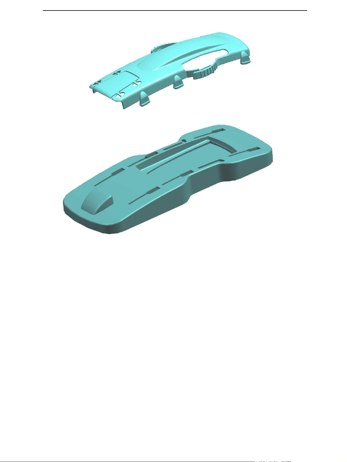
Disassembly jig opened
Install phone onto disassembly jig with grip opened.
NOTE: Remember to wear gloves or finger covers when working!!
Issue 2 11/02 ¤Nokia Corporation Page 1
Page 6
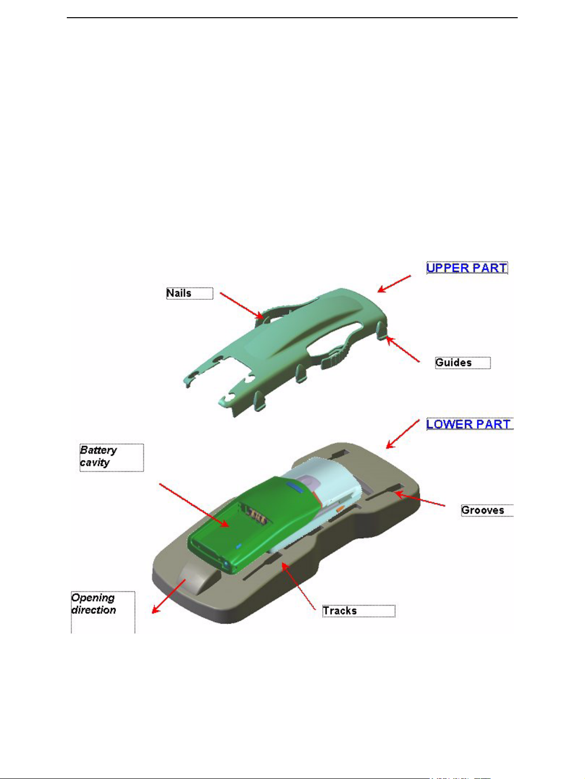
Phone with grip opened onto disassembly jig
1 Place the phone onto lower tool cavity upside down.
2 Install upper part on the lower part so that the nails are in the phone tracks.
3 And in the same time put the upper part guides to the lower part grooves.
4 Push the upper part till end of the grooves (opening direction).
5 Pull with your thumb from battery cavity to completely disassemble phone.
6 Push the upper part back to the starting point.
7 Remove the upper part.
CCS Technical Documentation
Page 2 ¤Nokia Corporation Issue 2 11/02
Page 7
CCS Technical Documentation
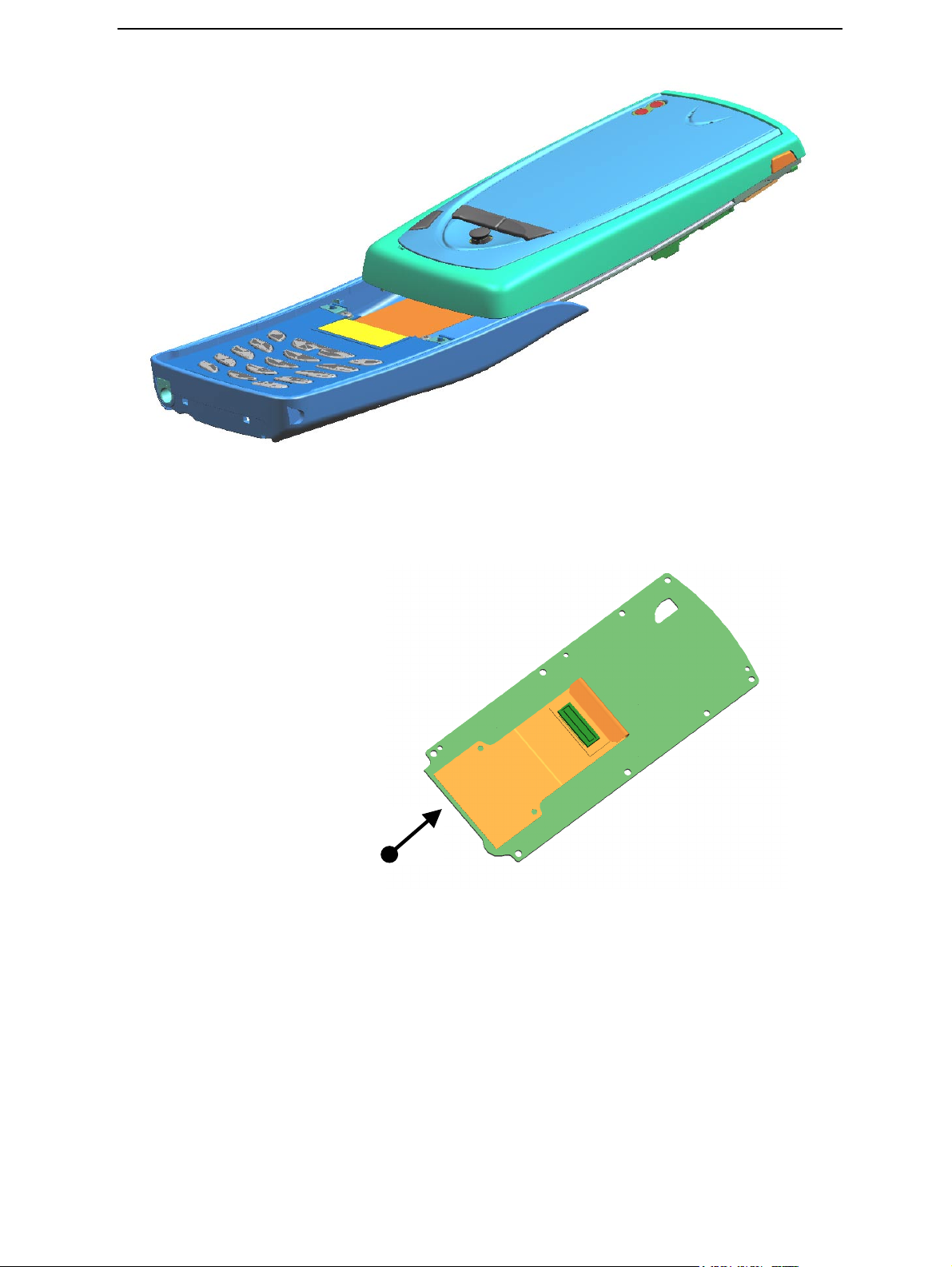
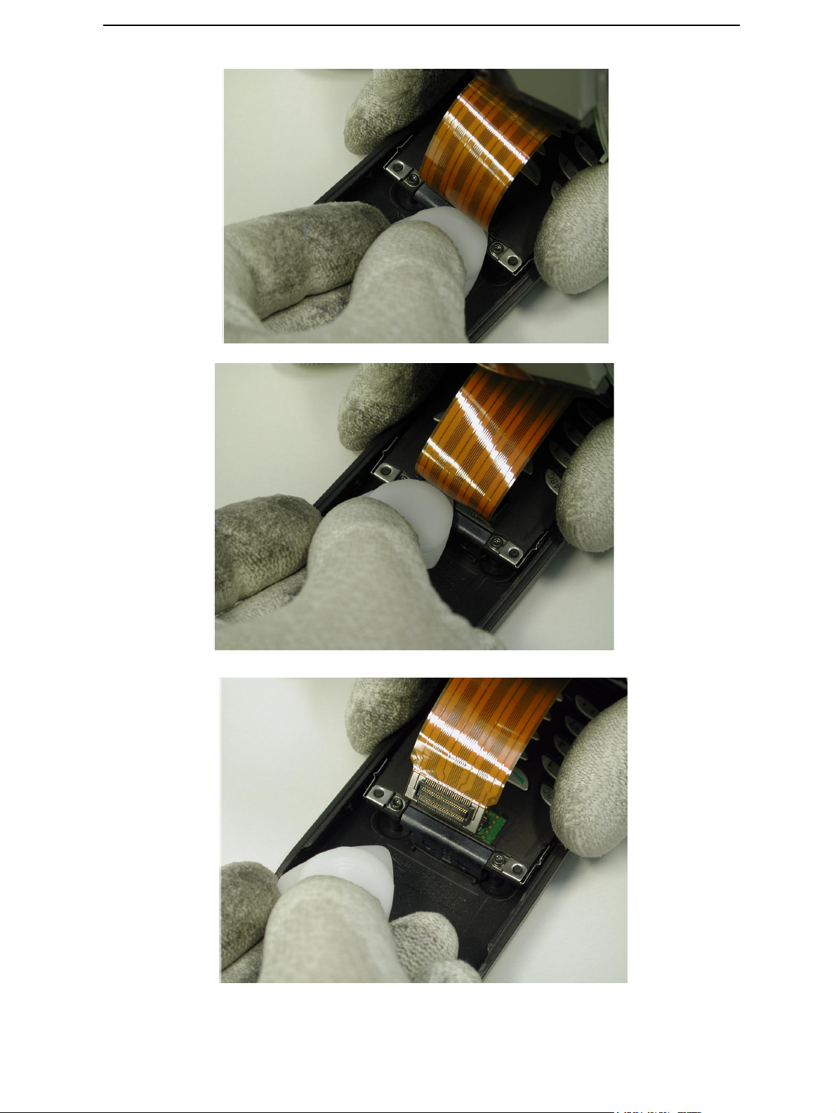
Push transceiver module to separate module from grip
Be careful when sliding transceiver away from grip module, preventing damage to flex
assembly.
Attention:
Be very careful not to
break the flex!
Solder joints to main
PWB.
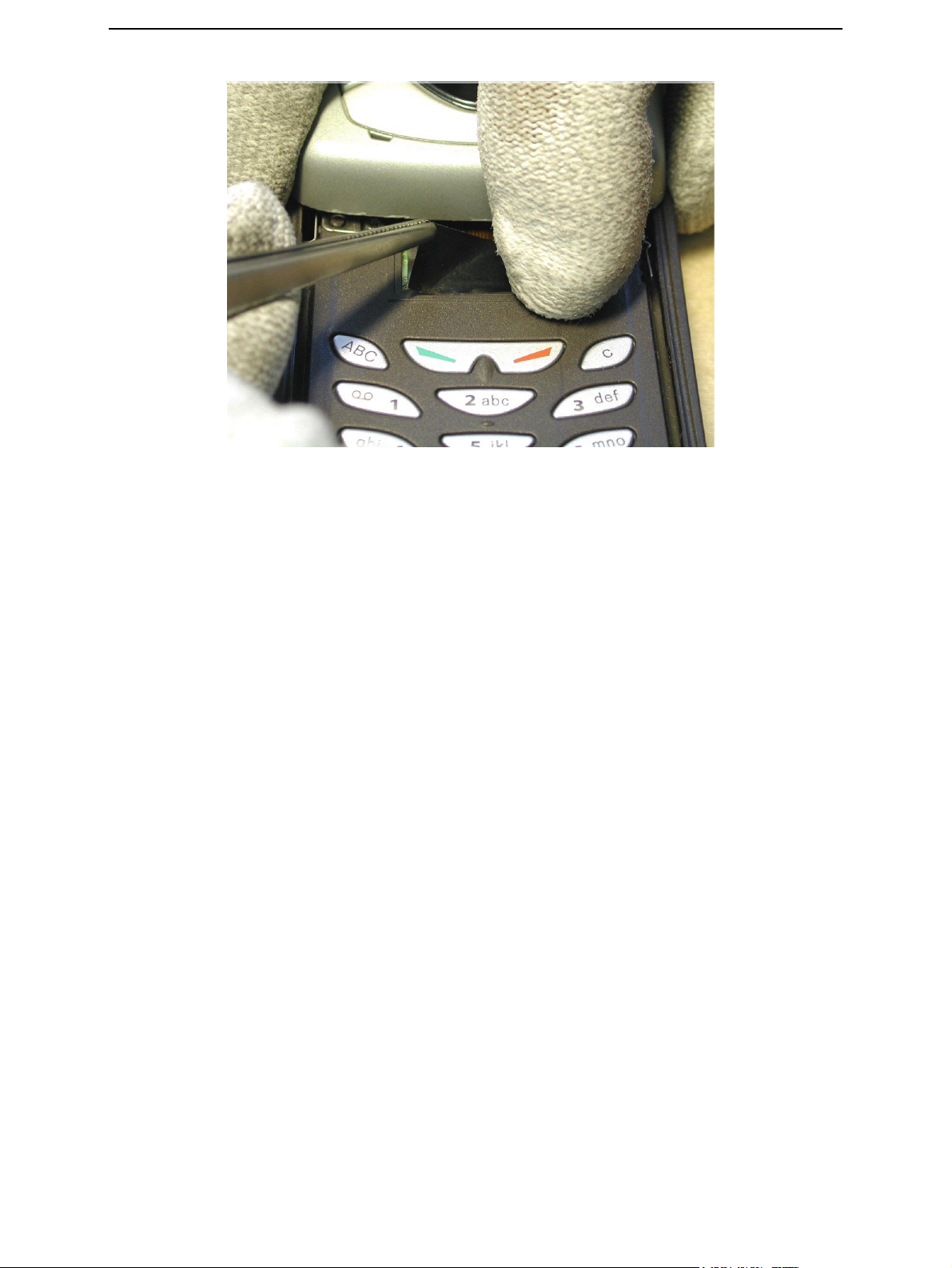
Protective tape disassembly from grip
1 Take with tweezers protective tape from one corner and drag the tape away.
2 At the same time do hold the connector at its place with other hand, preventing-
connector to be damaged.
Issue 2 11/02 ¤Nokia Corporation Page 3
Page 8
CCS Technical Documentation
Flex connector disassembly from grip
1 Take away battery cover.
2 Dismantle battery from transceiver.
3 Take the plastic SRT-6 opening tool.
4 Put one corner under the longer side of connector.
5 Gently rotate the plastic plate first from one side of connector then the other
side.
6 Connector will be released from grip.
7 Put Grip module to place where dust cannot reach the module.
Page 4 ¤Nokia Corporation Issue 2 11/02
Page 9
CCS Technical Documentation
Issue 2 11/02 ¤Nokia Corporation Page 5
Page 10
CCS Technical Documentation
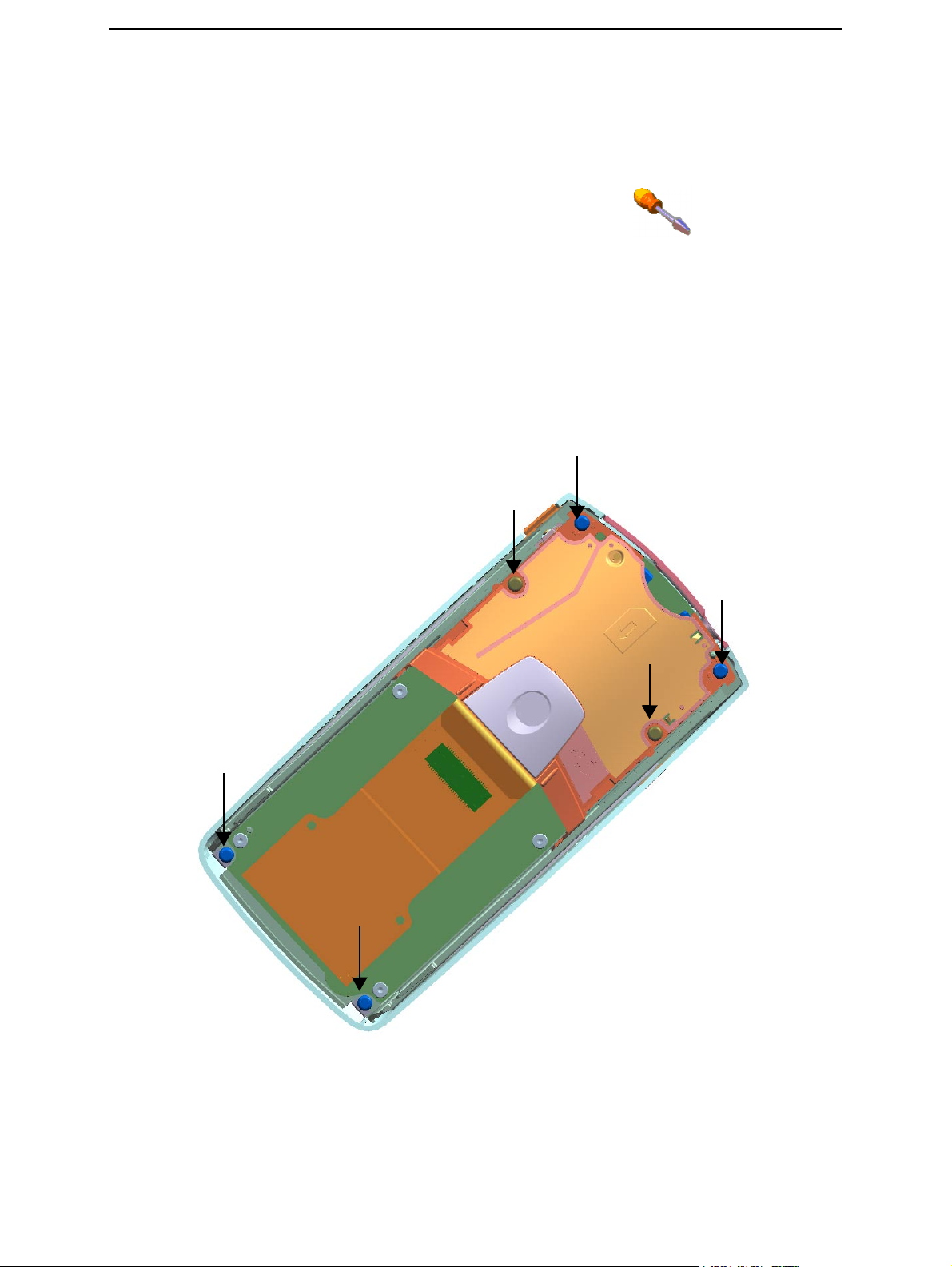
Transceiver module onto jig upside down, removing screws from A-cover and Acoustic chamber.
1 Take B-cover away from transceiver in hand.
2 Put transceiver onto table.
3 Remove screws RF 1,8x8,0 T6+ No. 5,6
4 Remove screws RF 1.8x6.0 T6+ No. 1,2,3,4
Note: Arrange screws so that you can remember where to place them when assembling.
5 Remove Acoustic Chamber from transceiver put it to a place where dust cannot
reach camera cavity.
Lift from sides!
5
4
1
6
2
3
Page 6 ¤Nokia Corporation Issue 2 11/02
Page 11

CCS Technical Documentation
Note for assembly! Screws must be tightenend as illustrated in the picture above, correct tightening sequence is 1,2,3,4,5,6.
1.Screws RFF 1.8x6.0 T6+ to acoustic chamber (2 pcs).
2.Screws RFF 1.8x6.0 T6+ to chassis assembly (2 pcs, bottom corners).
3.Screws RF 1.8x8.0 T6+ to acoustic chamber (2 pcs, top corners).
Note! If only acoustic chamber is removed and replaced, tightening sequence is then
1,2,5,6.
Issue 2 11/02 ¤Nokia Corporation Page 7
Page 12

Detaching A-cover from transceiver
1 Take the plastic SRT-6 opening tool put it between the A-cover and chassis
assembly from side 1 gently turning the blade.
2 Turning the transceiver upside, separate the A-cover from transceiver in hand.
3 Put transceiver onto jig, attention not to drop UI-module UI-module faces
upwards.
Figure 1: Detaching sequence 1
CCS Technical Documentation
Side 1
Page 8 ¤Nokia Corporation Issue 2 11/02
Page 13

CCS Technical Documentation
Figure 2: Detaching sequence 2
Figure 3: Detaching sequence 3
Issue 2 11/02 ¤Nokia Corporation Page 9
Page 14

Transceiver keymat from transceiver
1 Take away transceiver keymat.
2 Check that inner plastic part (white) of rocker will remain on keymat.
UI-Module
CCS Technical Documentation
Page 10 ¤Nokia Corporation Issue 2 11/02
Page 15

CCS Technical Documentation
UI-module B&B connector
1 Use plastic SRT-6 opening tool.
2 Put plastic SRT-6 opening tool under longer side of UI-module connector..
3 Gently separate B&B connector form UI-module by turning the tool
Issue 2 11/02 ¤Nokia Corporation Page 11
Page 16

UI-module from chassis assembly
1 Lift off the UI-module by hand from chassis assembly.
2 Place the UI-module (facing upwards) to a place where dust cannot reach UI-
module.
CCS Technical Documentation
Page 12 ¤Nokia Corporation Issue 2 11/02
Page 17

CCS Technical Documentation
SIM connector from acoustic chamber
1 Take acoustic chamber to hand.
2 Disconnect the sim connector with tweezers from front side.
3 Withdraw the sim connector from acoustic chamber.
Note! Sim connector can be loose in its cavity when assembled!
4 Be careful not to bend springs
Sim connector
springs
Withdrawal from
this side
Issue 2 11/02 ¤Nokia Corporation Page 13
Page 18

Camera module from acoustic chamber
1 Put plastic SRT-6 opening tool under the camera PWB
CCS Technical Documentation
2 With plastic SRT-6 opening tool gently pry out the camera from its housing by
turning tool (as in picture)
3 Be careful not to pop out the camera from its cavity.
Page 14 ¤Nokia Corporation Issue 2 11/02
Page 19

CCS Technical Documentation
4 Put camera to place where dust cannot access camera module.
5 If gasket is damaged replace acoustic chamber.
6 If guiding pin in acoustic chamber (for camera) is broken replace acoustic cham-
ber.
7 Acoustic chamber shall be put to place where dust cannot reach camera cavity.
Issue 2 11/02 ¤Nokia Corporation Page 15
Page 20

Dismantling main PWB from chassis assembly
1 Remove screws RF 1.6x4.4 T5+ 1,2,3,4
Note: Do not scratch PWB with screwdriving tool.
1
3
CCS Technical Documentation
2
4
Note: Assembly sequence for screws is as numbered. 1,2,3,4. Only one step:
1. Screws RFF 1.6x4.4 T5+ to Main PWB (4pcs).
Page 16 ¤Nokia Corporation Issue 2 11/02
Page 21

CCS Technical Documentation
Main PWB from chassis assembly
1 Take main PWB from chassis assembly by hand and put it onto table.
2 Take Hf-speaker from chassis put it onto table, be careful not to damage spring
or membrane.
3 Take earpiece from chassis with earpiece tool put it onto table.
4 Take headset from chassis with tweezers.
5 Microphone can also be removed with a sharp object.
Note: Magnetism in both HF speaker and earpiece pulls them together so be careful.
Issue 2 11/02 ¤Nokia Corporation Page 1
Page 22

Proximity sensor from chassis assembly:
1 Remove the proximity rubber with tweezers. In the picture below it is already
removed.
2 Use plastic SRT-6 opening tool.
3 Push proximity sensor snap to release it from chassis assembly.
CCS Technical Documentation
Page 2 ¤Nokia Corporation Issue 2 11/02
Page 23

CCS Technical Documentation
Proximity sensor from chassis assembly:
1 Lift away proximity sensor
Issue 2 11/02 ¤Nokia Corporation Page 3
Page 24

Power key from chassis assembly:
1 Use plastic SRT-6 opening tool
2 Push power key downwards to release it from chassis assembly.
CCS Technical Documentation
Page 4 ¤Nokia Corporation Issue 2 11/02
Page 25

CCS Technical Documentation
Dismantling keymat cover assembly from grip:
1 Grip to hand; remove screws PT 1.8x8.0 (2pcs). 1,2
2 Put fingers on both sides of battery connector
3 Pull upwards until battery connector is completely free from housing.
4 Slide keymat cover forward to release bottom from Grip.
5 Put Grip on pallet.
1
1
2
2,3,4,5
Issue 2 11/02 ¤Nokia Corporation Page 5
Page 26

Dismantling of keymat cover
1 Take keymat cover in hand so that battery connector is facing upwards.
2 Gently pry out the grip pwb Left side (first from upper side then bottom) from
keymat cover locking clips. Dismantle grip PWB sliding it to left side direction.
Note! When assembling grip PWB assemble first right side then left side.
3 Put grip PWB to a dust free place.
4 Lift away keymat from keymat cover.
Note! If new keymat is assembled remember to take protective tape away from key mat.
5 Pry out magnet with a sharp tool from keymat cover (be careful not to scratch
keymat cover).
CCS Technical Documentation
Page 6 ¤Nokia Corporation Issue 2 11/02
Page 27

CCS Technical Documentation
Dismantling of Battery connector from PWB
1 Take grip PWB in hand so that battery connector is facing to the right side.
2 Withdraw battery connector straight out from grip PWB
Issue 2 11/02 ¤Nokia Corporation Page 7
Page 28

Take Grip from pallet to hand
1 Remove the vibra from grip with tweezers. Grip with tweezers at shorter sides of
vibra.
2 Remove the battery cover locking latch with tweezers . Note! The guiding pin in
the locking latch goes in the groove in the grip.
3 Connect the charger plug to Dc-jack; carefully pry upwards the Dc-jack from
front side. Dc-jack will be released from grip.
1
CCS Technical Documentation
2
3
Page 8 ¤Nokia Corporation Issue 2 11/02
Page 29

CCS Technical Documentation
DC-jack released from grip sequencies
Issue 2 11/02 ¤Nokia Corporation Page 9
Page 30

CCS Technical Documentation
Page 10 ¤Nokia Corporation Issue 2 11/02
Page 31

CCS Technical Documentation
Grip module positioning springs
1 Positioning spring must be as showed in the picture.
2 End of the springs shall be toward keymat cover approx. + - 0,5mm.
Springs against
the bulb “seen in
picture”.
Tolerances
between springs
and keymat cover.
Issue 2 11/02 ¤Nokia Corporation Page 11
Page 32

Things to remember when assembling
• Assembling instructions are dismantling instructions backwards.
• You do not need any extra force.
• Screwdriving order is as screws are numbered.
• Tightening torque for all screws is 22Ncm, use torque wrench.
• Installing parts from pushing springs is forbidden.
• Do not touch springs vhen dismantling or assembling.
• All spring contacts and PWB pads are sensitive to dirt and grease for instance
from hands.
• Be careful not to touch spring contacts or PWB pads with bare hands. Always use
gloves.
CCS Technical Documentation
• New protective tape needed for grip flex.
Page 12 ¤Nokia Corporation Issue 2 11/02
Page 33

CCS Technical Documentation
Gripflex:
Plastic SRT-6 opening tool (for all disassembly sequences)
SRT-6 opening tool:
A-cover and UI-module
A-cover and UI-module
Gripflex
Issue 2 11/02 ¤Nokia Corporation Page 13
Page 34

CCS Technical Documentation
This page intentionally left blank.
Page 14 ¤Nokia Corporation Issue 2 11/02
 Loading...